EP2932603B1 - Rfic configuration for reduced antenna trace loss - Google Patents
Rfic configuration for reduced antenna trace loss Download PDFInfo
- Publication number
- EP2932603B1 EP2932603B1 EP13814771.5A EP13814771A EP2932603B1 EP 2932603 B1 EP2932603 B1 EP 2932603B1 EP 13814771 A EP13814771 A EP 13814771A EP 2932603 B1 EP2932603 B1 EP 2932603B1
- Authority
- EP
- European Patent Office
- Prior art keywords
- signals
- rfic
- antenna
- receiving
- module
- Prior art date
- Legal status (The legal status is an assumption and is not a legal conclusion. Google has not performed a legal analysis and makes no representation as to the accuracy of the status listed.)
- Active
Links
Images


Classifications
-
- H—ELECTRICITY
- H04—ELECTRIC COMMUNICATION TECHNIQUE
- H04B—TRANSMISSION
- H04B1/00—Details of transmission systems, not covered by a single one of groups H04B3/00 - H04B13/00; Details of transmission systems not characterised by the medium used for transmission
- H04B1/005—Details of transmission systems, not covered by a single one of groups H04B3/00 - H04B13/00; Details of transmission systems not characterised by the medium used for transmission adapting radio receivers, transmitters andtransceivers for operation on two or more bands, i.e. frequency ranges
- H04B1/0064—Details of transmission systems, not covered by a single one of groups H04B3/00 - H04B13/00; Details of transmission systems not characterised by the medium used for transmission adapting radio receivers, transmitters andtransceivers for operation on two or more bands, i.e. frequency ranges with separate antennas for the more than one band
Definitions
- the present application relates generally to the operation and design of wireless devices, and more particularly, to the configuration of radio frequency integrated circuit components for improved performance of a wireless device.
- Modern smart phones and other portable devices have extended the use of different wireless links with a variety of technologies in different radio frequency bands.
- Intense integration of multiple transceivers in one radio frequency integrated circuit (RFIC) chip or in one small module is increasingly required by consumer markets.
- RFIC radio frequency integrated circuit
- antenna dimensions remain fixed due to the frequency bands in which they operate.
- a typical smart phone may include two or more antennas to receive and transmit signals in various frequency bands.
- at least one of the antennas is located far from the device's RFIC, and this distance introduces undesirable trace loss. By reducing trace loss, it is possible that signal quality and/or overall performance of the device with respect to a particular antenna or frequency band can be improved.
- US 2004/0224652 A1 is directed to a wireless communication apparatus made up of a transmission circuit block including an antenna that is laid out such that the transmission lines, i.e., the sum of the distance connecting respective circuit blocks between an output terminal of the transmission power amplifier to an input/output terminal of the antenna is shorter than the transmission line, i.e., the sum of the distance connecting respective circuit blocks between an input terminal of a transmission power amplifier and an output terminal of a RFIC disposed at a preceding stage of the transmission power amplifier.
- FIG. 1 illustrates a conventional device 100 having multiple antennas configured to communicate in multiple RF bands.
- the device 100 comprises a smart phone or other wireless device.
- the device 100 includes antennas 102, 104, 106, and 108.
- Each antenna has a corresponding signal trace connecting it to an RFIC 110 that is configured to receive and/or transmit signals over the antennas.
- the signal traces may be routed on a circuit board or by dedicated connecting wires located within the device 100.
- the size of the antennas may necessitate their locations within the device 100.
- one or more of the antennas are located within the device 100 such that their corresponding signal traces to the RFIC 110 are long enough to experience significant trace loss.
- the antenna 104 is located relatively close to the RFIC 110 and its corresponding signal trace 114 is relatively short compared to the longer signal trace 112 associated with the antenna 108. Longer signal traces lead may lead to unacceptable trace loss that degrades the performance of the device.
- an RFIC configuration is provided to reduce antenna trace loss in multi-antenna devices.
- FIG. 2 shows a wireless device 200 comprising an exemplary embodiment of an RFIC configuration for reduced antenna trace loss.
- the wireless device 200 comprises a primary RFIC 202 that is coupled to antennas 206, 212 to transmit and/or receive RF signals with external devices.
- the wireless device 200 also comprises a secondary RFIC 204 that is coupled to antennas 208, 210 through signal traces 216 and 218 to transmit and/or receive RF signals with external devices.
- the antennas 208 and 210 are configured for communication using one or more communication technologies.
- the antenna 208 may be configured as a global navigation satellite system (GNSS) antenna to receive GNSS signals
- the antenna 210 may be configured as a wireless wide area network (WWAN) receiver (Rx) diversity antenna to communicate with a wide area network, for example, a cellular wide area network.
- GNSS global navigation satellite system
- WWAN wireless wide area network
- the antennas 208 and 210 are not limited to any particular communication technology and may be configured for use with any wireless technology, such as GNSS, WWAN, wireless local area network (WLAN), WiFi® (designating products using the IEEE 802.11 family of standards), Bluetooth (a wireless technology standard for exchanging data over short distances), or any other wireless technology.
- the secondary RFIC 204 receives analog signals from at least two antennas (i.e., the antennas 208, 210) and processes one or both of these signals to produce at least one analog output signal 214 that is input to the primary RFIC 202.
- the analog output signal 214 may be further processed by the primary RFIC 202 as discussed in more detail below.
- the secondary RFIC 204 performs at least the following functions.
- the novel RFIC configuration comprises the secondary RFIC 204 which is located within a wireless device so that trace loss associated with one or more antennas connected to the secondary RFIC can be reduced.
- trace loss associated with one or more antennas connected to the secondary RFIC can be reduced.
- at least one of the signal traces 216 and 218 connecting the antennas 208 and 210 to the secondary RFIC 204 is shorter and experiences less trace loss than if these signal traces were extended to connect the antennas 208 and 210 to the primary RFIC 202. The shorter signal traces result in reduced trace loss.
- FIG. 3 shows an exemplary embodiment of the secondary RFIC 204.
- the secondary RFIC 204 comprises a first module 302 and a second module 304.
- the first module 302 processes signals that flow to/from the antenna 208.
- the second module 304 processes signals that flow to/from the antenna 210.
- the antennas 208, 210 are configured to receive signals having the same or different frequency.
- the first module 302 communicates with the primary RFIC 202 (not shown) through communication line 214.
- the second module 304 communicates with other functional elements at the device through the communication line 306.
- each module is configured to process at least one of global navigation satellite system (GNSS) signals, wireless wide area network (WWAN) communication signals, Wi-Fi communication signals, and Bluetooth communication signals.
- GNSS global navigation satellite system
- WWAN wireless wide area network
- Wi-Fi communication signals Wi-Fi communication signals
- Bluetooth communication signals The antennas 208, 210 are configured to operate in the corresponding frequency bands.
- the first module 302 receives analog RF signals from the antenna 208 and processes these signals to generate the analog output 214.
- the processing includes but is not limited to amplification, filtering, downconverting or any other suitable process.
- the analog output 214 can be further processed by the primary RFIC.
- the processing performed by the first module 302 comprises a sub-process associated with processing performed by the primary RFIC.
- the first module 302 is coupled to multiple antennas.
- one or more antennas in addition to the antenna 208 are coupled to the first module 302.
- the first module 302 processes the multiple antennas coupled to it to generate the analog output 214 to the primary RFIC.
- the secondary RFIC 204 is configured to process signals that flow to/from at least two antennas and provide a processed analog signal to the primary RFIC 202 using the communication line 214.
- This configuration allows the secondary RFIC 204 to be positioned within the device so that antenna traces to the secondary RFIC 204 are short. As a result, the shorter trace lengths result in reduced trace loss.
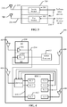
- FIG. 4 shows a wireless device 400 comprising an exemplary embodiment of an RFIC configuration that includes the secondary RFIC 204 that provides reduced antenna trace loss.
- the device 400 comprises antennas 402, 404, 406, and 408.
- a primary RFIC 410 is configured to receive signals from antennas 404 and 408.
- the secondary RFIC 204 is configured to receive signals from antennas 402 and 406.
- the secondary RFIC 204 includes a first module (M1) comprising an LNA 302 that processes signals received from the antenna 402 in a first frequency band.
- the secondary RFIC 204 also includes a second module (M2) that comprises a receive circuit 304 that processes signals received from the antenna 406 in a second frequency band.
- the receive circuit 304 may be a GNSS receive circuit that processes GNSS signals received by the antenna 406. The processed GNSS signals are then passed to a GNSS processor 412 for further processing at the device 400.
- the GNSS processor 412 is located at the receiver 304 so that the GNSS front end is located in the secondary RFIC 204.
- the secondary RFIC 204 is configured to comprise a variety of functional configurations to process analog signals associated with at least two antennas.
- the secondary RFIC 204 is configured to process the analog antenna signals it receives from the antennas 402 and 406 and generate at least one analog output signal 214.
- the secondary RFIC 204 may provide amplification, down-conversion, filtering and/or any other functions to process the received analog signals from two or more antennas to produce the analog output signal 214.
- the antenna 402 may be a GNSS antenna and its received signal may be amplified by the LNA 302.
- the analog output of the LNA 302 is transmitted to the primary RFIC 410 in the analog signal 214.
- the primary RFIC 410 comprises receiver 412 that receives the amplified analog signal and performs further processing.
- the receiver 412 may be a GNSS front end processor that processes the amplified GNSS signal to perform position/location functions.
- the processing performed by the first module 302 comprises a sub-process associated with processing performed by the receiver 412 of the primary RFIC 400.
- the antenna 406 may be a WWAN Rx diversity antenna and its received signal may be input to the second module M2 which may comprise a WWAN Rx diversity receiver 304 configured to receive and down-convert a WWAN Rx diversity signal.
- the secondary RFIC 204 By positioning the secondary RFIC 204 closer to at least one of the antennas 402 and 406, the trace loss associated with the input signal paths of the antennas 402, 406 is reduced as compared to the conventional device configuration shown in FIG. 1 .
- the antenna 406 may be configured to receive WiFi signals and the receiver 304 is configured to process the received WiFi signals.
- the secondary RFIC 204 may receive and process signals associated with any communication or information technology. It should also be noted that the novel configuration is not limited to having only one secondary RFIC, such that any number of secondary RFICs can be utilized.
- the novel RFIC configuration comprises at least one secondary RFIC configured to process analog signals from at least two antennas.
- the secondary RFIC is positioned close to its respective antennas to reduce trace length and thereby reduce trace loss.
- one or more of the following features are provided by the novel RFIC configuration.
- FIG. 5 shows an exemplary embodiment of an apparatus 500 comprising an RFIC configuration for reduce antenna trace loss.
- the apparatus 500 is implemented by one or more modules configured to provide the functions as described herein.
- each module comprises hardware and/or hardware executing software.
- the apparatus 500 comprises a first module comprising means ( 502 ) for receiving first signals from a first antenna, which in an aspect comprises the primary RFIC 202.
- the apparatus 500 also comprises a second module comprising means ( 504 ) for receiving analog signals from at least two additional antennas, the means for receiving the analog signals configured to process selected analog signals received from at least one additional antenna to generate an analog output that is input to the means for receiving the first signals, which in an aspect comprises the secondary RFIC 204.
- transistor types and technologies may be substituted, rearranged or otherwise modified to achieve the same results.
- circuits shown utilizing PMOS transistors may be modified to use NMOS transistors and vice versa.
- the amplifiers disclosed herein may be realized using a variety of transistor types and technologies and are not limited to those transistor types and technologies illustrated in the Drawings.
- transistors types such as BJT, GaAs, MOSFET or any other transistor technology may be used.
- DSP Digital Signal Processor
- ASIC Application Specific Integrated Circuit
- FPGA Field Programmable Gate Array
- a general purpose processor may be a microprocessor, but in the alternative, the processor may be any conventional processor, controller, microcontroller, or state machine.
- a processor may also be implemented as a combination of computing devices, e.g., a combination of a DSP and a microprocessor, a plurality of microprocessors, one or more microprocessors in conjunction with a DSP core, or any other such configuration.
- a software module may reside in Random Access Memory (RAM), flash memory, Read Only Memory (ROM), Electrically Programmable ROM (EPROM), Electrically Erasable Programmable ROM (EEPROM), registers, hard disk, a removable disk, a CD-ROM, or any other form of storage medium known in the art.
- An exemplary storage medium is coupled to the processor such that the processor can read information from, and write information to, the storage medium.
- the storage medium may be integral to the processor.
- the processor and the storage medium may reside in an ASIC.
- the ASIC may reside in a user terminal.
- the processor and the storage medium may reside as discrete components in a user terminal.
- the functions described may be implemented in hardware, software, firmware, or any combination thereof. If implemented in software, the functions may be stored on or transmitted over as one or more instructions or code on a computer-readable medium.
- Computer-readable media includes both non-transitory computer storage media and communication media including any medium that facilitates transfer of a computer program from one place to another.
- a non-transitory storage media may be any available media that can be accessed by a computer.
- such computer-readable media can comprise RAM, ROM, EEPROM, CD-ROM or other optical disk storage, magnetic disk storage or other magnetic storage devices, or any other medium that can be used to carry or store desired program code in the form of instructions or data structures and that can be accessed by a computer.
- any connection is properly termed a computer-readable medium.
- the software is transmitted from a website, server, or other remote source using a coaxial cable, fiber optic cable, twisted pair, digital subscriber line (DSL), or wireless technologies such as infrared, radio, and microwave
- the coaxial cable, fiber optic cable, twisted pair, DSL, or wireless technologies such as infrared, radio, and microwave are included in the definition of medium.
- Disk and disc includes compact disc (CD), laser disc, optical disc, digital versatile disc (DVD), floppy disk and blu-ray disc where disks usually reproduce data magnetically, while discs reproduce data optically with lasers. Combinations of the above should also be included within the scope of computer-readable media.
Landscapes
- Engineering & Computer Science (AREA)
- Computer Networks & Wireless Communication (AREA)
- Signal Processing (AREA)
- Transceivers (AREA)
- Input Circuits Of Receivers And Coupling Of Receivers And Audio Equipment (AREA)
- Variable-Direction Aerials And Aerial Arrays (AREA)
- Mobile Radio Communication Systems (AREA)
Applications Claiming Priority (2)
| Application Number | Priority Date | Filing Date | Title |
|---|---|---|---|
| US13/712,607 US9350392B2 (en) | 2012-12-12 | 2012-12-12 | RFIC configuration for reduced antenna trace loss |
| PCT/US2013/074823 WO2014093716A2 (en) | 2012-12-12 | 2013-12-12 | Rfic configuration for reduced antenna trace loss |
Publications (2)
| Publication Number | Publication Date |
|---|---|
| EP2932603A2 EP2932603A2 (en) | 2015-10-21 |
| EP2932603B1 true EP2932603B1 (en) | 2019-11-27 |
Family
ID=49885473
Family Applications (1)
| Application Number | Title | Priority Date | Filing Date |
|---|---|---|---|
| EP13814771.5A Active EP2932603B1 (en) | 2012-12-12 | 2013-12-12 | Rfic configuration for reduced antenna trace loss |
Country Status (11)
| Country | Link |
|---|---|
| US (1) | US9350392B2 (enExample) |
| EP (1) | EP2932603B1 (enExample) |
| JP (1) | JP6419714B2 (enExample) |
| KR (1) | KR102113577B1 (enExample) |
| CN (1) | CN104838592B (enExample) |
| AP (1) | AP2015008517A0 (enExample) |
| EA (1) | EA029590B1 (enExample) |
| EC (1) | ECSP15029619A (enExample) |
| MA (1) | MA38179B1 (enExample) |
| SA (1) | SA515360530B1 (enExample) |
| WO (1) | WO2014093716A2 (enExample) |
Families Citing this family (4)
| Publication number | Priority date | Publication date | Assignee | Title |
|---|---|---|---|---|
| WO2009053910A2 (en) | 2007-10-22 | 2009-04-30 | Mobileaccess Networks Ltd. | Communication system using low bandwidth wires |
| WO2013142662A2 (en) | 2012-03-23 | 2013-09-26 | Corning Mobile Access Ltd. | Radio-frequency integrated circuit (rfic) chip(s) for providing distributed antenna system functionalities, and related components, systems, and methods |
| US9184960B1 (en) | 2014-09-25 | 2015-11-10 | Corning Optical Communications Wireless Ltd | Frequency shifting a communications signal(s) in a multi-frequency distributed antenna system (DAS) to avoid or reduce frequency interference |
| KR102715432B1 (ko) | 2019-04-05 | 2024-10-10 | 삼성전자주식회사 | 안테나 모듈 및 중간 주파수 집적 회로 사이의 중간 주파수 신호의 손실을 보상하는 전자 장치 |
Family Cites Families (17)
| Publication number | Priority date | Publication date | Assignee | Title |
|---|---|---|---|---|
| US6456245B1 (en) | 2000-12-13 | 2002-09-24 | Magis Networks, Inc. | Card-based diversity antenna structure for wireless communications |
| US6882829B2 (en) | 2002-04-02 | 2005-04-19 | Texas Instruments Incorporated | Integrated circuit incorporating RF antenna switch and power amplifier |
| JP4011555B2 (ja) * | 2003-04-24 | 2007-11-21 | シャープ株式会社 | 無線機能内蔵情報処理端末装置 |
| US6998709B2 (en) | 2003-11-05 | 2006-02-14 | Broadcom Corp. | RFIC die-package configuration |
| US7643848B2 (en) | 2004-04-13 | 2010-01-05 | Qualcomm, Incorporated | Multi-antenna transceiver system |
| US20060063494A1 (en) * | 2004-10-04 | 2006-03-23 | Xiangdon Zhang | Remote front-end for a multi-antenna station |
| US7313414B2 (en) | 2004-12-13 | 2007-12-25 | Broadcom Corporation | Method and system for mobile receiver antenna architecture for European cellular and broadcasting services |
| JP4169158B2 (ja) | 2004-12-24 | 2008-10-22 | インターナショナル・ビジネス・マシーンズ・コーポレーション | 無線icチップおよびこれを用いた位置認識システム並びにセキュリティシステム |
| US8130787B2 (en) | 2006-01-17 | 2012-03-06 | Hitachi Metals, Ltd. | High-frequency circuit device, and communications apparatus comprising same |
| US8314706B2 (en) * | 2007-11-16 | 2012-11-20 | Rcd Technology Corporation | Coupled radio frequency identification (RFID) and biometric device |
| US8174385B2 (en) * | 2008-09-29 | 2012-05-08 | Mitac Technology Corp. | Radio frequency identification reader having antennas in different directions |
| JP4640500B2 (ja) * | 2008-12-15 | 2011-03-02 | パナソニック電工株式会社 | 無線中継装置 |
| JP2010226374A (ja) * | 2009-03-23 | 2010-10-07 | Toshiba Corp | マルチバンド無線機 |
| CN201839326U (zh) * | 2010-08-13 | 2011-05-18 | 宇龙计算机通信科技(深圳)有限公司 | 一种翻盖式移动终端 |
| JP2012107921A (ja) * | 2010-11-16 | 2012-06-07 | Seiko Epson Corp | 受信信号判定方法、プログラム、測位装置、及び電子機器 |
| JP5884737B2 (ja) * | 2011-01-13 | 2016-03-15 | 日本電気株式会社 | 無線通信装置 |
| US9882602B2 (en) | 2011-06-29 | 2018-01-30 | Qualcomm Incorporated | Global navigation satellite system receiver with filter bypass mode for improved sensitivity |
-
2012
- 2012-12-12 US US13/712,607 patent/US9350392B2/en active Active
-
2013
- 2013-12-12 EA EA201591117A patent/EA029590B1/ru unknown
- 2013-12-12 JP JP2015547575A patent/JP6419714B2/ja active Active
- 2013-12-12 MA MA38179A patent/MA38179B1/fr unknown
- 2013-12-12 WO PCT/US2013/074823 patent/WO2014093716A2/en not_active Ceased
- 2013-12-12 AP AP2015008517A patent/AP2015008517A0/xx unknown
- 2013-12-12 CN CN201380064624.3A patent/CN104838592B/zh active Active
- 2013-12-12 EP EP13814771.5A patent/EP2932603B1/en active Active
- 2013-12-12 KR KR1020157018077A patent/KR102113577B1/ko active Active
-
2015
- 2015-06-04 SA SA515360530A patent/SA515360530B1/ar unknown
- 2015-07-10 EC ECIEPI201529619A patent/ECSP15029619A/es unknown
Non-Patent Citations (1)
| Title |
|---|
| None * |
Also Published As
| Publication number | Publication date |
|---|---|
| JP2016504857A (ja) | 2016-02-12 |
| EA029590B1 (ru) | 2018-04-30 |
| US20140162570A1 (en) | 2014-06-12 |
| KR102113577B1 (ko) | 2020-05-21 |
| KR20150095753A (ko) | 2015-08-21 |
| WO2014093716A2 (en) | 2014-06-19 |
| US9350392B2 (en) | 2016-05-24 |
| WO2014093716A3 (en) | 2014-10-30 |
| MA38179B1 (fr) | 2017-07-31 |
| MA38179A1 (fr) | 2016-04-29 |
| EP2932603A2 (en) | 2015-10-21 |
| EA201591117A1 (ru) | 2015-09-30 |
| ECSP15029619A (es) | 2016-01-29 |
| AP2015008517A0 (en) | 2015-06-30 |
| CN104838592A (zh) | 2015-08-12 |
| CN104838592B (zh) | 2018-11-27 |
| SA515360530B1 (ar) | 2017-10-26 |
| JP6419714B2 (ja) | 2018-11-07 |
Similar Documents
| Publication | Publication Date | Title |
|---|---|---|
| TWI759498B (zh) | 傳送裝置與傳收裝置 | |
| US11283584B2 (en) | High frequency module | |
| US8933858B2 (en) | Front end parallel resonant switch | |
| US9031518B2 (en) | Concurrent hybrid matching network | |
| US9014648B2 (en) | Diversity receiver with shared local oscillator signal in diversity mode | |
| US9373879B2 (en) | Compact power divider/combiner with flexible output spacing | |
| JP2014526173A (ja) | 高められた感度のための、フィルタバイパスモードを有するグローバル・ナビゲーション衛星システム受信機 | |
| CN106879062B (zh) | 用于发射接收系统的装置、方法和存储介质 | |
| EP2932603B1 (en) | Rfic configuration for reduced antenna trace loss | |
| US20210258023A1 (en) | Multiband Transmitter | |
| JP2013528341A (ja) | 同一周波数帯域におけるラジオ周波数信号に対するアンテナ共有 | |
| CN107104696A (zh) | 射频通信装置和方法 | |
| US20100056204A1 (en) | Radio frequency communication devices and methods | |
| EP2897222B1 (en) | High isolation antenna structure on a ground plane | |
| US9026060B2 (en) | Bidirectional matching network | |
| US9548767B2 (en) | Multi-band amplifier | |
| OA17424A (en) | RFIC configuration for reduced antenna trace loss. | |
| US20240348280A1 (en) | Systems and methods for reducing harmonics in communication modules | |
| US9252820B2 (en) | Circuit and mobile communication device | |
| KR20160087329A (ko) | 수신기, 무선 단말 및 무선 단말의 동작 방법 |
Legal Events
| Date | Code | Title | Description |
|---|---|---|---|
| PUAI | Public reference made under article 153(3) epc to a published international application that has entered the european phase |
Free format text: ORIGINAL CODE: 0009012 |
|
| 17P | Request for examination filed |
Effective date: 20150707 |
|
| AK | Designated contracting states |
Kind code of ref document: A2 Designated state(s): AL AT BE BG CH CY CZ DE DK EE ES FI FR GB GR HR HU IE IS IT LI LT LU LV MC MK MT NL NO PL PT RO RS SE SI SK SM TR |
|
| AX | Request for extension of the european patent |
Extension state: BA ME |
|
| DAX | Request for extension of the european patent (deleted) | ||
| STAA | Information on the status of an ep patent application or granted ep patent |
Free format text: STATUS: EXAMINATION IS IN PROGRESS |
|
| 17Q | First examination report despatched |
Effective date: 20181108 |
|
| GRAP | Despatch of communication of intention to grant a patent |
Free format text: ORIGINAL CODE: EPIDOSNIGR1 |
|
| STAA | Information on the status of an ep patent application or granted ep patent |
Free format text: STATUS: GRANT OF PATENT IS INTENDED |
|
| INTG | Intention to grant announced |
Effective date: 20190628 |
|
| RIN1 | Information on inventor provided before grant (corrected) |
Inventor name: ZHAO, LIANG Inventor name: LIN, I-HSIANG Inventor name: XIONG, ZHIJIE Inventor name: KRISHNAMOORTHY, SESHAGIRI Inventor name: AKULA, PRASHANTH Inventor name: KO, JIN-SU Inventor name: ZHAO, DESONG Inventor name: WANG, KEVIN HSI HUAI |
|
| GRAS | Grant fee paid |
Free format text: ORIGINAL CODE: EPIDOSNIGR3 |
|
| GRAA | (expected) grant |
Free format text: ORIGINAL CODE: 0009210 |
|
| STAA | Information on the status of an ep patent application or granted ep patent |
Free format text: STATUS: THE PATENT HAS BEEN GRANTED |
|
| AK | Designated contracting states |
Kind code of ref document: B1 Designated state(s): AL AT BE BG CH CY CZ DE DK EE ES FI FR GB GR HR HU IE IS IT LI LT LU LV MC MK MT NL NO PL PT RO RS SE SI SK SM TR |
|
| REG | Reference to a national code |
Ref country code: GB Ref legal event code: FG4D |
|
| REG | Reference to a national code |
Ref country code: CH Ref legal event code: EP |
|
| REG | Reference to a national code |
Ref country code: AT Ref legal event code: REF Ref document number: 1207886 Country of ref document: AT Kind code of ref document: T Effective date: 20191215 |
|
| REG | Reference to a national code |
Ref country code: DE Ref legal event code: R096 Ref document number: 602013063423 Country of ref document: DE |
|
| REG | Reference to a national code |
Ref country code: IE Ref legal event code: FG4D |
|
| REG | Reference to a national code |
Ref country code: NL Ref legal event code: MP Effective date: 20191127 |
|
| REG | Reference to a national code |
Ref country code: LT Ref legal event code: MG4D |
|
| PG25 | Lapsed in a contracting state [announced via postgrant information from national office to epo] |
Ref country code: NO Free format text: LAPSE BECAUSE OF FAILURE TO SUBMIT A TRANSLATION OF THE DESCRIPTION OR TO PAY THE FEE WITHIN THE PRESCRIBED TIME-LIMIT Effective date: 20200227 Ref country code: GR Free format text: LAPSE BECAUSE OF FAILURE TO SUBMIT A TRANSLATION OF THE DESCRIPTION OR TO PAY THE FEE WITHIN THE PRESCRIBED TIME-LIMIT Effective date: 20200228 Ref country code: NL Free format text: LAPSE BECAUSE OF FAILURE TO SUBMIT A TRANSLATION OF THE DESCRIPTION OR TO PAY THE FEE WITHIN THE PRESCRIBED TIME-LIMIT Effective date: 20191127 Ref country code: LT Free format text: LAPSE BECAUSE OF FAILURE TO SUBMIT A TRANSLATION OF THE DESCRIPTION OR TO PAY THE FEE WITHIN THE PRESCRIBED TIME-LIMIT Effective date: 20191127 Ref country code: SE Free format text: LAPSE BECAUSE OF FAILURE TO SUBMIT A TRANSLATION OF THE DESCRIPTION OR TO PAY THE FEE WITHIN THE PRESCRIBED TIME-LIMIT Effective date: 20191127 Ref country code: LV Free format text: LAPSE BECAUSE OF FAILURE TO SUBMIT A TRANSLATION OF THE DESCRIPTION OR TO PAY THE FEE WITHIN THE PRESCRIBED TIME-LIMIT Effective date: 20191127 Ref country code: FI Free format text: LAPSE BECAUSE OF FAILURE TO SUBMIT A TRANSLATION OF THE DESCRIPTION OR TO PAY THE FEE WITHIN THE PRESCRIBED TIME-LIMIT Effective date: 20191127 Ref country code: BG Free format text: LAPSE BECAUSE OF FAILURE TO SUBMIT A TRANSLATION OF THE DESCRIPTION OR TO PAY THE FEE WITHIN THE PRESCRIBED TIME-LIMIT Effective date: 20200227 |
|
| PG25 | Lapsed in a contracting state [announced via postgrant information from national office to epo] |
Ref country code: IS Free format text: LAPSE BECAUSE OF FAILURE TO SUBMIT A TRANSLATION OF THE DESCRIPTION OR TO PAY THE FEE WITHIN THE PRESCRIBED TIME-LIMIT Effective date: 20200327 Ref country code: RS Free format text: LAPSE BECAUSE OF FAILURE TO SUBMIT A TRANSLATION OF THE DESCRIPTION OR TO PAY THE FEE WITHIN THE PRESCRIBED TIME-LIMIT Effective date: 20191127 Ref country code: HR Free format text: LAPSE BECAUSE OF FAILURE TO SUBMIT A TRANSLATION OF THE DESCRIPTION OR TO PAY THE FEE WITHIN THE PRESCRIBED TIME-LIMIT Effective date: 20191127 |
|
| PG25 | Lapsed in a contracting state [announced via postgrant information from national office to epo] |
Ref country code: AL Free format text: LAPSE BECAUSE OF FAILURE TO SUBMIT A TRANSLATION OF THE DESCRIPTION OR TO PAY THE FEE WITHIN THE PRESCRIBED TIME-LIMIT Effective date: 20191127 |
|
| PG25 | Lapsed in a contracting state [announced via postgrant information from national office to epo] |
Ref country code: ES Free format text: LAPSE BECAUSE OF FAILURE TO SUBMIT A TRANSLATION OF THE DESCRIPTION OR TO PAY THE FEE WITHIN THE PRESCRIBED TIME-LIMIT Effective date: 20191127 Ref country code: DK Free format text: LAPSE BECAUSE OF FAILURE TO SUBMIT A TRANSLATION OF THE DESCRIPTION OR TO PAY THE FEE WITHIN THE PRESCRIBED TIME-LIMIT Effective date: 20191127 Ref country code: EE Free format text: LAPSE BECAUSE OF FAILURE TO SUBMIT A TRANSLATION OF THE DESCRIPTION OR TO PAY THE FEE WITHIN THE PRESCRIBED TIME-LIMIT Effective date: 20191127 Ref country code: PT Free format text: LAPSE BECAUSE OF FAILURE TO SUBMIT A TRANSLATION OF THE DESCRIPTION OR TO PAY THE FEE WITHIN THE PRESCRIBED TIME-LIMIT Effective date: 20200419 Ref country code: CZ Free format text: LAPSE BECAUSE OF FAILURE TO SUBMIT A TRANSLATION OF THE DESCRIPTION OR TO PAY THE FEE WITHIN THE PRESCRIBED TIME-LIMIT Effective date: 20191127 Ref country code: RO Free format text: LAPSE BECAUSE OF FAILURE TO SUBMIT A TRANSLATION OF THE DESCRIPTION OR TO PAY THE FEE WITHIN THE PRESCRIBED TIME-LIMIT Effective date: 20191127 |
|
| REG | Reference to a national code |
Ref country code: CH Ref legal event code: PL |
|
| REG | Reference to a national code |
Ref country code: BE Ref legal event code: MM Effective date: 20191231 |
|
| REG | Reference to a national code |
Ref country code: DE Ref legal event code: R097 Ref document number: 602013063423 Country of ref document: DE |
|
| PG25 | Lapsed in a contracting state [announced via postgrant information from national office to epo] |
Ref country code: SK Free format text: LAPSE BECAUSE OF FAILURE TO SUBMIT A TRANSLATION OF THE DESCRIPTION OR TO PAY THE FEE WITHIN THE PRESCRIBED TIME-LIMIT Effective date: 20191127 Ref country code: MC Free format text: LAPSE BECAUSE OF FAILURE TO SUBMIT A TRANSLATION OF THE DESCRIPTION OR TO PAY THE FEE WITHIN THE PRESCRIBED TIME-LIMIT Effective date: 20191127 Ref country code: SM Free format text: LAPSE BECAUSE OF FAILURE TO SUBMIT A TRANSLATION OF THE DESCRIPTION OR TO PAY THE FEE WITHIN THE PRESCRIBED TIME-LIMIT Effective date: 20191127 |
|
| REG | Reference to a national code |
Ref country code: AT Ref legal event code: MK05 Ref document number: 1207886 Country of ref document: AT Kind code of ref document: T Effective date: 20191127 |
|
| PLBE | No opposition filed within time limit |
Free format text: ORIGINAL CODE: 0009261 |
|
| STAA | Information on the status of an ep patent application or granted ep patent |
Free format text: STATUS: NO OPPOSITION FILED WITHIN TIME LIMIT |
|
| PG25 | Lapsed in a contracting state [announced via postgrant information from national office to epo] |
Ref country code: IE Free format text: LAPSE BECAUSE OF NON-PAYMENT OF DUE FEES Effective date: 20191212 Ref country code: LU Free format text: LAPSE BECAUSE OF NON-PAYMENT OF DUE FEES Effective date: 20191212 |
|
| 26N | No opposition filed |
Effective date: 20200828 |
|
| PG25 | Lapsed in a contracting state [announced via postgrant information from national office to epo] |
Ref country code: LI Free format text: LAPSE BECAUSE OF NON-PAYMENT OF DUE FEES Effective date: 20191231 Ref country code: PL Free format text: LAPSE BECAUSE OF FAILURE TO SUBMIT A TRANSLATION OF THE DESCRIPTION OR TO PAY THE FEE WITHIN THE PRESCRIBED TIME-LIMIT Effective date: 20191127 Ref country code: CH Free format text: LAPSE BECAUSE OF NON-PAYMENT OF DUE FEES Effective date: 20191231 Ref country code: SI Free format text: LAPSE BECAUSE OF FAILURE TO SUBMIT A TRANSLATION OF THE DESCRIPTION OR TO PAY THE FEE WITHIN THE PRESCRIBED TIME-LIMIT Effective date: 20191127 Ref country code: BE Free format text: LAPSE BECAUSE OF NON-PAYMENT OF DUE FEES Effective date: 20191231 Ref country code: AT Free format text: LAPSE BECAUSE OF FAILURE TO SUBMIT A TRANSLATION OF THE DESCRIPTION OR TO PAY THE FEE WITHIN THE PRESCRIBED TIME-LIMIT Effective date: 20191127 |
|
| PG25 | Lapsed in a contracting state [announced via postgrant information from national office to epo] |
Ref country code: IT Free format text: LAPSE BECAUSE OF FAILURE TO SUBMIT A TRANSLATION OF THE DESCRIPTION OR TO PAY THE FEE WITHIN THE PRESCRIBED TIME-LIMIT Effective date: 20191127 |
|
| PG25 | Lapsed in a contracting state [announced via postgrant information from national office to epo] |
Ref country code: CY Free format text: LAPSE BECAUSE OF FAILURE TO SUBMIT A TRANSLATION OF THE DESCRIPTION OR TO PAY THE FEE WITHIN THE PRESCRIBED TIME-LIMIT Effective date: 20191127 |
|
| PG25 | Lapsed in a contracting state [announced via postgrant information from national office to epo] |
Ref country code: HU Free format text: LAPSE BECAUSE OF FAILURE TO SUBMIT A TRANSLATION OF THE DESCRIPTION OR TO PAY THE FEE WITHIN THE PRESCRIBED TIME-LIMIT; INVALID AB INITIO Effective date: 20131212 Ref country code: MT Free format text: LAPSE BECAUSE OF FAILURE TO SUBMIT A TRANSLATION OF THE DESCRIPTION OR TO PAY THE FEE WITHIN THE PRESCRIBED TIME-LIMIT Effective date: 20191127 |
|
| PG25 | Lapsed in a contracting state [announced via postgrant information from national office to epo] |
Ref country code: TR Free format text: LAPSE BECAUSE OF FAILURE TO SUBMIT A TRANSLATION OF THE DESCRIPTION OR TO PAY THE FEE WITHIN THE PRESCRIBED TIME-LIMIT Effective date: 20191127 |
|
| PG25 | Lapsed in a contracting state [announced via postgrant information from national office to epo] |
Ref country code: MK Free format text: LAPSE BECAUSE OF FAILURE TO SUBMIT A TRANSLATION OF THE DESCRIPTION OR TO PAY THE FEE WITHIN THE PRESCRIBED TIME-LIMIT Effective date: 20191127 |
|
| PGFP | Annual fee paid to national office [announced via postgrant information from national office to epo] |
Ref country code: DE Payment date: 20251118 Year of fee payment: 13 |
|
| PGFP | Annual fee paid to national office [announced via postgrant information from national office to epo] |
Ref country code: GB Payment date: 20251113 Year of fee payment: 13 |
|
| PGFP | Annual fee paid to national office [announced via postgrant information from national office to epo] |
Ref country code: FR Payment date: 20251111 Year of fee payment: 13 |