EP2932221B1 - Verfahren zur dichteprüfung eines gehäuses - Google Patents
Verfahren zur dichteprüfung eines gehäuses Download PDFInfo
- Publication number
- EP2932221B1 EP2932221B1 EP13836226.4A EP13836226A EP2932221B1 EP 2932221 B1 EP2932221 B1 EP 2932221B1 EP 13836226 A EP13836226 A EP 13836226A EP 2932221 B1 EP2932221 B1 EP 2932221B1
- Authority
- EP
- European Patent Office
- Prior art keywords
- housing
- pressure
- temperature
- sensor
- chamber
- Prior art date
- Legal status (The legal status is an assumption and is not a legal conclusion. Google has not performed a legal analysis and makes no representation as to the accuracy of the status listed.)
- Not-in-force
Links
- 238000000034 method Methods 0.000 title description 42
- 238000012360 testing method Methods 0.000 title description 22
- 238000005259 measurement Methods 0.000 claims description 40
- 230000008859 change Effects 0.000 claims description 35
- 238000001514 detection method Methods 0.000 claims description 7
- 239000007789 gas Substances 0.000 description 27
- 229910052734 helium Inorganic materials 0.000 description 14
- 239000001307 helium Substances 0.000 description 14
- SWQJXJOGLNCZEY-UHFFFAOYSA-N helium atom Chemical compound [He] SWQJXJOGLNCZEY-UHFFFAOYSA-N 0.000 description 14
- 230000008569 process Effects 0.000 description 12
- 238000011156 evaluation Methods 0.000 description 11
- IJGRMHOSHXDMSA-UHFFFAOYSA-N Atomic nitrogen Chemical compound N#N IJGRMHOSHXDMSA-UHFFFAOYSA-N 0.000 description 10
- 238000003466 welding Methods 0.000 description 10
- 230000008901 benefit Effects 0.000 description 7
- 238000009530 blood pressure measurement Methods 0.000 description 6
- 230000001419 dependent effect Effects 0.000 description 6
- 238000005516 engineering process Methods 0.000 description 6
- 238000004364 calculation method Methods 0.000 description 5
- 238000001816 cooling Methods 0.000 description 5
- 229910052757 nitrogen Inorganic materials 0.000 description 5
- 238000010998 test method Methods 0.000 description 5
- 230000007613 environmental effect Effects 0.000 description 3
- 238000004519 manufacturing process Methods 0.000 description 3
- 239000012528 membrane Substances 0.000 description 3
- 238000012544 monitoring process Methods 0.000 description 3
- 238000007789 sealing Methods 0.000 description 3
- 238000005476 soldering Methods 0.000 description 3
- XUIMIQQOPSSXEZ-UHFFFAOYSA-N Silicon Chemical compound [Si] XUIMIQQOPSSXEZ-UHFFFAOYSA-N 0.000 description 2
- 238000010276 construction Methods 0.000 description 2
- 230000000694 effects Effects 0.000 description 2
- 238000010438 heat treatment Methods 0.000 description 2
- 239000000203 mixture Substances 0.000 description 2
- 229910052710 silicon Inorganic materials 0.000 description 2
- 239000010703 silicon Substances 0.000 description 2
- FIKFLLIUPUVONI-UHFFFAOYSA-N 8-(2-phenylethyl)-1-oxa-3,8-diazaspiro[4.5]decan-2-one;hydrochloride Chemical compound Cl.O1C(=O)NCC11CCN(CCC=2C=CC=CC=2)CC1 FIKFLLIUPUVONI-UHFFFAOYSA-N 0.000 description 1
- 101100489713 Saccharomyces cerevisiae (strain ATCC 204508 / S288c) GND1 gene Proteins 0.000 description 1
- 101100489717 Saccharomyces cerevisiae (strain ATCC 204508 / S288c) GND2 gene Proteins 0.000 description 1
- UDWPONKAYSRBTJ-UHFFFAOYSA-N [He].[N] Chemical compound [He].[N] UDWPONKAYSRBTJ-UHFFFAOYSA-N 0.000 description 1
- 230000000712 assembly Effects 0.000 description 1
- 238000000429 assembly Methods 0.000 description 1
- 238000009529 body temperature measurement Methods 0.000 description 1
- 238000004891 communication Methods 0.000 description 1
- 238000011109 contamination Methods 0.000 description 1
- 238000007796 conventional method Methods 0.000 description 1
- 238000012937 correction Methods 0.000 description 1
- 230000008878 coupling Effects 0.000 description 1
- 238000010168 coupling process Methods 0.000 description 1
- 238000005859 coupling reaction Methods 0.000 description 1
- 230000007423 decrease Effects 0.000 description 1
- 239000012530 fluid Substances 0.000 description 1
- -1 for example Substances 0.000 description 1
- 239000003365 glass fiber Substances 0.000 description 1
- 238000007689 inspection Methods 0.000 description 1
- 238000009434 installation Methods 0.000 description 1
- 230000010354 integration Effects 0.000 description 1
- 238000000691 measurement method Methods 0.000 description 1
- 230000007246 mechanism Effects 0.000 description 1
- 238000004377 microelectronic Methods 0.000 description 1
- 230000003287 optical effect Effects 0.000 description 1
- 230000005693 optoelectronics Effects 0.000 description 1
- 230000035515 penetration Effects 0.000 description 1
- 239000000700 radioactive tracer Substances 0.000 description 1
- 230000035945 sensitivity Effects 0.000 description 1
- 239000000758 substrate Substances 0.000 description 1
- 230000001960 triggered effect Effects 0.000 description 1
- 238000009423 ventilation Methods 0.000 description 1
Images



Classifications
-
- G—PHYSICS
- G01—MEASURING; TESTING
- G01M—TESTING STATIC OR DYNAMIC BALANCE OF MACHINES OR STRUCTURES; TESTING OF STRUCTURES OR APPARATUS, NOT OTHERWISE PROVIDED FOR
- G01M3/00—Investigating fluid-tightness of structures
- G01M3/02—Investigating fluid-tightness of structures by using fluid or vacuum
- G01M3/26—Investigating fluid-tightness of structures by using fluid or vacuum by measuring rate of loss or gain of fluid, e.g. by pressure-responsive devices, by flow detectors
- G01M3/32—Investigating fluid-tightness of structures by using fluid or vacuum by measuring rate of loss or gain of fluid, e.g. by pressure-responsive devices, by flow detectors for containers, e.g. radiators
- G01M3/3236—Investigating fluid-tightness of structures by using fluid or vacuum by measuring rate of loss or gain of fluid, e.g. by pressure-responsive devices, by flow detectors for containers, e.g. radiators by monitoring the interior space of the containers
- G01M3/3272—Investigating fluid-tightness of structures by using fluid or vacuum by measuring rate of loss or gain of fluid, e.g. by pressure-responsive devices, by flow detectors for containers, e.g. radiators by monitoring the interior space of the containers for verifying the internal pressure of closed containers
-
- G—PHYSICS
- G01—MEASURING; TESTING
- G01L—MEASURING FORCE, STRESS, TORQUE, WORK, MECHANICAL POWER, MECHANICAL EFFICIENCY, OR FLUID PRESSURE
- G01L19/00—Details of, or accessories for, apparatus for measuring steady or quasi-steady pressure of a fluent medium insofar as such details or accessories are not special to particular types of pressure gauges
- G01L19/0092—Pressure sensor associated with other sensors, e.g. for measuring acceleration or temperature
-
- G—PHYSICS
- G01—MEASURING; TESTING
- G01L—MEASURING FORCE, STRESS, TORQUE, WORK, MECHANICAL POWER, MECHANICAL EFFICIENCY, OR FLUID PRESSURE
- G01L9/00—Measuring steady of quasi-steady pressure of fluid or fluent solid material by electric or magnetic pressure-sensitive elements; Transmitting or indicating the displacement of mechanical pressure-sensitive elements, used to measure the steady or quasi-steady pressure of a fluid or fluent solid material, by electric or magnetic means
- G01L9/02—Measuring steady of quasi-steady pressure of fluid or fluent solid material by electric or magnetic pressure-sensitive elements; Transmitting or indicating the displacement of mechanical pressure-sensitive elements, used to measure the steady or quasi-steady pressure of a fluid or fluent solid material, by electric or magnetic means by making use of variations in ohmic resistance, e.g. of potentiometers, electric circuits therefor, e.g. bridges, amplifiers or signal conditioning
- G01L9/06—Measuring steady of quasi-steady pressure of fluid or fluent solid material by electric or magnetic pressure-sensitive elements; Transmitting or indicating the displacement of mechanical pressure-sensitive elements, used to measure the steady or quasi-steady pressure of a fluid or fluent solid material, by electric or magnetic means by making use of variations in ohmic resistance, e.g. of potentiometers, electric circuits therefor, e.g. bridges, amplifiers or signal conditioning of piezo-resistive devices
- G01L9/065—Measuring steady of quasi-steady pressure of fluid or fluent solid material by electric or magnetic pressure-sensitive elements; Transmitting or indicating the displacement of mechanical pressure-sensitive elements, used to measure the steady or quasi-steady pressure of a fluid or fluent solid material, by electric or magnetic means by making use of variations in ohmic resistance, e.g. of potentiometers, electric circuits therefor, e.g. bridges, amplifiers or signal conditioning of piezo-resistive devices with temperature compensating means
-
- G—PHYSICS
- G01—MEASURING; TESTING
- G01M—TESTING STATIC OR DYNAMIC BALANCE OF MACHINES OR STRUCTURES; TESTING OF STRUCTURES OR APPARATUS, NOT OTHERWISE PROVIDED FOR
- G01M3/00—Investigating fluid-tightness of structures
- G01M3/02—Investigating fluid-tightness of structures by using fluid or vacuum
- G01M3/26—Investigating fluid-tightness of structures by using fluid or vacuum by measuring rate of loss or gain of fluid, e.g. by pressure-responsive devices, by flow detectors
- G01M3/32—Investigating fluid-tightness of structures by using fluid or vacuum by measuring rate of loss or gain of fluid, e.g. by pressure-responsive devices, by flow detectors for containers, e.g. radiators
- G01M3/3236—Investigating fluid-tightness of structures by using fluid or vacuum by measuring rate of loss or gain of fluid, e.g. by pressure-responsive devices, by flow detectors for containers, e.g. radiators by monitoring the interior space of the containers
Definitions
- the present invention relates to metrology.
- the present invention relates to a measuring arrangement for determining a leakage rate of a housing for receiving a device for satellites and space applications.
- the invention relates to a method for determining a leakage rate of a gas in a housing for receiving an electrical device for use in space.
- electronic assemblies are arranged in a housing, which connects via suitable electrical connections arranged in the housing components to the outside.
- the housing itself is tight, in particular hermetically sealed, designed so that due to external variable pressure conditions, the pressure in the housing remains substantially the same and there provided a gas composition does not change substantially.
- Hermetically sealed housings are inspected for leak tightness during manufacture to ensure that, especially as long as products have not yet arrived at their application site, for example in a satellite application in orbit, thus in a vacuum, moisture can not penetrate.
- Suitable test methods can be found in the standards for hybrids MIL-STD-883J, METHOD 1014.14 or components MIL-STD-750F, METHOD 1071.
- Commonly used are methods with a tracer gas. For example, helium leak tests or "GALDEN bombing" methods can be carried out for measuring coarse and fine leaks as well as for the search for large leaks.
- GALDEN bombing helium leak tests or "GALDEN bombing" methods can be carried out for measuring coarse and fine leaks as well as for the search for large leaks.
- these methods have been developed mainly for the testing of small devices and already have a significant age.
- a helium leak rate is usually determined which is only in the mathematical relation with an actual, specified, equivalent air leak rate.
- the so-called "helium bombing” may require relatively long bombing times.
- a hermetically sealed chamber for a density test can not always be physically separated from the remainder of a module, hence its environmental electronics outside the chamber.
- Helium adhering to or embedded in the surrounding electronics, mechanical parts, glass fibers, coaxial plugs or cavities may also not permit or at least complicate the measurement of a helium leak rate.
- a reliable inference to a proper hermeticity may not always be possible.
- test devices that are suitable for performing the aforementioned tests may not be suitable because of the above-described alignment of the test methods with small devices, larger devices such as those described e.g. be used in a satellite application to be able to test.
- a housing component may be hermetically sealed using a suitable bonding technique, such as a welding process, particularly laser welding.
- a suitable bonding technique such as a welding process, particularly laser welding.
- GALDEN is usually not applicable as a medium for the identification of large leaks due to possible contamination and unwanted penetration into parts outside the hermetically sealed chamber. Although another test option would be an optical inspection to detect gross leaks, this is a relatively insecure process.
- a measurement of the leakage rate can advantageously also take place in orbit and at variable temperatures.
- a safe pressure to prevent corona and arc flashovers can be monitored by secondary emissions.
- a device could thus be timely and early shut down via, for example, a built-in automatic or by telemetry.
- a forecast could be leak-dependent Pressure drops are generated over time.
- a pressure measurement in the housing after 5 years of operation in orbit could allow conclusions about the condition of a device. For example, this could include a comparison of a measured pressure with a previously calculated setpoint pressure, from which statements about a lifetime of a device could possibly be derived.
- the device is de-energized during a measurement process, so no power dissipation occurs. This can have the advantage that, for example, resulting heat loss does not falsify a measurement result.
- a pressure difference between the housing interior and the environment is necessary. This can affect both a negative pressure and an overpressure of the environment relative to the housing interior.
- an in-orbit use of the housing corresponds to a vacuum situation in which an ambient pressure is lower than a pressure inside the housing.
- the housings may have internal volumes in the range of a few cubic centimeters, for example, about 1 to 15 cubic centimeters.
- the sensor elements may, according to one example, have a size which allows installation in even smaller housings.
- the evaluation unit can be, for example, a computer-controlled multimeter which contains a processor which calculates the leakage rate on the basis of a suitably designed software including the output signals and output variables of the sensors as well as the measurement times.
- the measuring arrangement can be used according to an example by multiplexing the measurement for housing or devices in the multi-benefit.
- a fast electronic switching of the measuring device can be used to different housing and pressure sensors.
- up to 10 devices can be monitored with one measuring device.
- the measuring arrangement further comprises a hermetically sealable chamber with a pressure adjusting device which is designed to set a chamber internal pressure.
- the chamber is designed to accommodate the housing with the pressure sensor and temperature sensor in your interior.
- This may for example be a vacuum chamber with a calibrated pressure sensor and a controllable valve for ventilation.
- a chamber pressure can be variably adjusted.
- the chamber further comprises a chamber pressure sensor for detecting the chamber internal pressure.
- the chamber pressure sensor is configured to output a reference signal for adjustment of the output signal of the pressure sensor.
- the pressure sensor arranged in the device can hereby be calibrated by comparing the signal generated by this pressure sensor with the reference signal.
- the chamber has a receptacle for the housing and further a temperature adjusting device which is adapted to adjust the temperature within the housing.
- This recording device may for example be a test platform, which is arranged within a vacuum chamber and which is temperature-controlled. This can have the advantage that defined temperature conditions can be created, which can be advantageous, for example, for a calibration of the sensors.
- the pressure sensor has a constant current source which is temperature-compensated. This may have the advantage that when changing a temperature of the constant current source no change in the current and thus no distortion of pressure readings results.
- the constant current source has a current source temperature sensor for detecting a temperature of the constant current source. Furthermore, the evaluation unit is designed to compensate for a temperature-induced change in a current of the constant current source based on an output signal of the current source temperature sensor. In other words, a possible temperature-induced error of the constant current source can be considered mathematically or calculated out of a preliminary measurement result. This can increase the accuracy of the measurement.
- the temperature sensor is arranged in the housing. This can have the advantage that the temperature sensor is arranged directly in the gas itself and thereby with improved heat coupling and thus can generate better measurement results.
- the temperature sensor can also be arranged outside the housing, with a good thermal connection between the external temperature sensor and the gas inside the housing being sought.
- the device is an electronic amplifier.
- the amplifier may be a microwave power amplifier for use in space, for example in a satellite.
- a method for determining a leakage rate of a gas in a housing for receiving an electrical device comprises the following steps: providing a pressure sensor in the housing, providing a temperature sensor, providing a timing device, closing the housing, detecting a pressure change with the pressure sensor, detecting a corresponding temperature change with the temperature sensor and determining the corresponding measurement times with the timing device and determining the leakage rate of the housing by an evaluation unit based on the pressure change, the temperature change and the measurement times.
- Detecting the pressure change and the temperature change can take place in an example during the use of the housing and the device in space, but also on the ground, for example in the context of a manufacturing process.
- the measurement times may determine a period of time during which a pressure drop occurs.
- the instantaneous pressure and the instantaneous temperature can be measured at a defined time. These measurements can be repeated at a second defined point in time, resulting in a measurement period on the one hand, and the corresponding pressure change and temperature change in this period on the other hand.
- the evaluation unit can calculate a leakage rate using, for example, suitable software, taking into account the physical relationships.
- a period between a first measurement time and a second measurement time is between 30 and 60 hours, and a pressure change is 0.1 to 3 mbar.
- the determination of the leakage rate is calculated by compensating for the temperature-dependent volume expansion of the enclosed gas.
- the method prior to the step of closing the housing, includes the step of determining a temperature coefficient of the pressure sensor.
- the determination of the leakage rate is still based on the temperature coefficient of the pressure sensor.
- determining the temperature coefficient of the pressure sensor comprises the steps of: setting a constant pressure in the housing, changing a temperature in the housing, detecting an output voltage change at the pressure sensor, calculating the temperature coefficient of the pressure sensor based on the output voltage change and the temperature in the housing , In other words, a dependence of the output voltage of the pressure sensor is detected by a change in temperature in order to take this into account in the form of a determined temperature coefficient in the determination of the leakage rate. This can increase accuracy of leakage rate measurement.
- the housing is arranged in a hermetically sealable chamber and open, so that by a change in a chamber pressure and the pressure in the housing is adjustable.
- the further step of determining a temperature coefficient of the constant current source prior to the step of closing the housing, the further step of determining a temperature coefficient of the constant current source.
- a temperature-independent constant current source may be required in particular for the pressure sensor.
- Determining the leakage rate is still based on the temperature coefficient of the constant current source.
- a possible temperature-induced error of the constant current source can be compensated by the evaluation unit. This can increase the accuracy of the measurement and the calculation of the leakage rate.
- determining the temperature coefficient of the constant current source comprises the steps of: providing a current source temperature sensor to the constant current source, wherein the current source temperature sensor is configured to detect a temperature of the constant current source. Further, there is provided a current measuring device for measuring a current of the constant current source, changing a temperature of the constant current source, detecting a change of the current of the constant current source with the current measuring device, and determining the temperature coefficient of the constant current source based on the change of the temperature and the change of the current. In other words, a corresponding temperature-induced change in the current intensity is detected by purposefully changing the temperature, and the temperature coefficient of the constant current source is determined therefrom. This can be taken into account by the evaluation unit in the calculation of the leakage rate, which can increase an accuracy of the calculation of the leakage rate.
- a method for testing the tightness of a housing and a corresponding housing component are provided, which realizes a novel, simplified leak test, in particular without any special external measurement effort.
- a method of testing the tightness of a housing comprising the steps of i) providing a pressure sensor in a housing, the pressure sensor being arranged to detect a pressure in the housing, ii) closing the housing, and iii) detecting a pressure in the housing Casing.
- a housing component comprising a housing having an internal volume and a sensor element configured to detect a pressure in the housing internal volume.
- a platform in particular a satellite, is displayed with a housing component.
- a housing component is used in an overpressure, vacuum, or vacuum application.
- a hermetically sealed housing for sealing integrated microelectronics, in which housing or its housing interior volume a pressure sensor is provided which determines the chamber pressure of an enclosed gas, for example nitrogen, helium or a nitrogen helium -Mix, directly and in particular to any Measure time. From certain pressure conditions or a time profile of pressure conditions or pressures can be concluded taking into account the gas temperature thus on a leakage rate of the housing.
- the internal pressure of a hermetically sealed housing is temperature-dependent due to the known physical relationships. For example, a temperature coefficient of an enclosed gas may be 3.66 mbar / K. In order to detect in particular small leaks, it may be necessary to measure comparatively small pressure differences over a longer period of time, for example 1 mbar over a period of 48 hours.
- detecting the pressure may include detecting an equivalent air leak rate or a pressure change over time.
- a possible sensor element or pressure sensor is a MEMS (Micro Electro Mechanical System) chip sensor, for example of the type MS 7801 of the manufacturer MEAS.
- MEMS Micro Electro Mechanical System
- Such sensor elements are suitable for use in hybrid circuits for satellite applications, e.g. Microwave modules or hybrid optoelectronic modules for satellite communications applications. It should also be noted that hermetically sealed hybrid modules are also used in military or medical applications.
- Capacitive MEMS sensors that change their capacitance by means of an applied pressure or piezoresistive MEMS sensors, which directly deliver a linear, pressure-dependent voltage when a constant source current is applied.
- the previously mentioned MS7801 sensor is a piezoresistive MEMS chip sensor.
- Such a sensor may have an internal vacuum reference chamber with a silicon membrane and thereby enables absolute pressure measurements in the range of 0 to 1 bar or vacuum to normal atmosphere.
- the method can directly determine equivalent air leak rates specified in the aforementioned MIL standards. These are in accordance with MIL-STD-883J (Classes S, K and V for Space) on a 3 cm 3 large chamber volume with 1.0 * 10 -8 atm * cm 3 / s (mbar * l / s) or according to MIL-STD-750F for a 3 cm 3 chamber volume of 1.0 * 10 -8 atm * cm 3 / s (mbar * l / s) ,
- detecting the pressure may include detecting a pressure drop when the housing is located in a vacuum environment and / or detecting a pressure increase when the housing is located in an overpressure environment.
- the method may detect either a pressure decay in a vacuum or vacuum environment or the pressure rise in an overpressure environment. Only the hermetically sealed chamber of the housing, thus the inner volume of the housing is checked. The method is thus independent of other environmental effects. Furthermore, the typical "bombing", the pushing in of detector gas in an overpressure chamber, typically up to 72 hours at 3 bar, can be dispensed with, as used, for example, in a helium leak test.
- the pressure may be detected in a controlled positive pressure environment for a defined unit of time, in particular during a bombing process.
- this bombing time can be used directly as a measurement time for a pressure increase. This results in a significant time savings compared to a helium process.
- a case temperature increase may occur in the housing causing a first housing internal pressure, wherein in a subsequent cooling process, the housing internal pressure decreases to a second housing internal pressure, wherein detecting the pressure comprises detecting the pressure drop in the housing from the first housing internal pressure may include the second housing internal pressure.
- a working temperature when closing the housing and / or the tightness of the sealed housing may be determinable.
- the trapped gas e.g., nitrogen
- the heated gas cools down again. This results in a pressure drop in the housing or in the inner volume of the housing due to the temperature coefficient of the trapped gas according to Gay-Lussac. This temperature coefficient is 1 / 273.15 / K at a starting temperature of 0 ° C.
- a pressure drop after the connection process to, for example, 847 mbar immediately establishes a pressure difference with respect to the atmospheric pressure or the external pressure of the housing, which allows a subsequent leak test pressure measurement without additional overpressure or vacuum device.
- Large leaks in the range of 10 -3 to 10 -4 mbar * l / s can be detected within less than a minute.
- the closing of the housing by welding or soldering takes place.
- the detected pressure may be forwardable to other electronics in the housing and / or outside the housing.
- the pressure information can thus be processed directly in the housing of suitable electronics to initiate appropriate measures, for example, when detecting a non-dense state.
- suitable electronics for example, when detecting a non-dense state.
- the same can be done by electronics outside the housing, wherein the detection in the housing allows a self-contained electronic module in a housing component.
- a leak rate of the housing may be directly determinable using a defined housing internal volume value and a time pressure change.
- the sensor element may be calibrated using a multi-point measurement.
- the sensor element may be precisely calibrated for each module separately via a multi-point pressure measurement based on atmospheric pressure and vacuum using a calibrated meter. This may be done as a fully automatic procedure, whereby an air leakage rate can be calculated directly via the pressure drop and a given housing volume, which may be housing specific.
- the pressure sensor may be designed to be temperature-compensated.
- the pressure sensor may be temperature-compensated. This compensation can for a target temperature during operation, which for example by Set self-heating of the object due to its power dissipation, done, whereby the measurement by the pressure sensor can be preferred. Corresponding compensation may be required according to a MIL standard.
- the temperature coefficient (e.g., according to Gay-Lussac) of an enclosed gas, for example, nitrogen may be computationally compensated by a factor, for example, 3.411 ⁇ 10-3 / K for an initial temperature of 20 ° C.
- the temperature dependence of the measured gas pressure is calculated by means of suitable software.
- a pressure measurement can be temperature-independent within wide limits. This applies in particular in the case that a leak test measurement is carried out exclusively in a comparatively small temperature window of, for example, +/- 3 ° C.
- the measuring method is largely independent of the filling gas, since the dynamic viscosity values of the preferably used gases, the viscosity values being responsible for the passage of a leak, are substantially similar or at least strongly similar.
- detecting the pressure of the housing internal volume may be substantially continuous throughout the life of a housing component.
- the pressure sensor in the housing can thus be the measurement of a pressure drop at any operating time of Housing module done.
- an in-orbit monitoring of the hermeticity of a module over its entire lifetime is made possible.
- FIG. 1 an exemplary embodiment of the arrangement of sensor elements in a housing component according to the present invention is shown.
- FIG. 1 shows a housing component 2, more precisely a part of a housing component or its underside.
- a plurality of contact elements 6 is provided, which leave this on one side of the housing component 2.
- the contact elements 6 constitute a conductive connection from the interior or inner volume 8 of the housing component 2 to the outside.
- the contact elements 6 can thus provide mechanical fastening and / or electrical contacting of the housing component 2 with external further electronic components.
- sensor element 4 is provided in the inner volume 8 of the housing component 2. In an application scenario, however, only a single sensor element 4 may be provided.
- Sensor element 4a may in this case be a MEMS chip sensor element which is bonded in the housing component, while sensor element 4b may be a capacitive MEMS chip sensor.
- FIG. 1 Further electronic components which may be arranged in the housing component 2 in an operating case are in FIG. 1 not shown further. However, these other components may also be suitably connectable to the outside of the housing component 2 using the contact elements 6.
- FIG. 2 an exemplary embodiment of an electronic circuit with sensor element for mounting in a housing component according to the present invention is shown.
- FIG. 2 shows an exemplary embodiment of a radiometric instrumentation amplifier.
- the exact configuration or the field of application of the circuit is not relevant to the inventive concept.
- a sensor element 4 is provided on a printed circuit board 14 of the circuit 10 by way of example. Also arranged on the printed circuit board 14 are contact elements 6, which can suitably pierce a housing wall of the housing component 2 or else suitably to the contact elements 6 of FIG FIG. 1 are connectable.
- FIG. 2 thus shows the integration of a sensor element 4 in a circuit. Required connections such as a power supply and measuring outputs for the sensor element 4 may be provided directly on the printed circuit board 14.
- the sensor element 4 can thus be functionally and logically integrated into the circuit 10. Furthermore, the circuit behavior of the circuit 10 can be influenced depending on a measured value of the sensor element 4.
- FIG. 3 For example, an exemplary measurement of a leak rate on a hermetically sealed module with and without temperature compensation of the present invention is shown.
- FIG. 4 an exemplary construction of a sensor element according to the present invention is shown.
- FIG. 4 shows an exemplary embodiment of the sensor element 4, constructed as a Wheatstone bridge of piezosensitive resistors 12 on a silicon membrane.
- the Wheatstone bridge has an input for a supply voltage V s + , which is exemplarily connected directly to the epitaxial layer of the membrane of a sealed vacuum reference cavity.
- piezosensitive resistors 12 which are connected by supply voltage V s + to ground (GND1 or GND2). Each two resistors 12 are connected to the positive output Out + and the negative output Out-.
- FIG. 5 is an exemplary embodiment of offset and temperature compensation of the sensor element of FIG. 4 shown.
- the Wheatstone bridge of piezosensitive resistors 12 of FIG. 4 complemented by three resistors R1, R2 and R3, on the one hand using the resistors R1 and R2 offset compensation (zero point in vacuum) and using resistor R3 allow temperature compensation.
- the required elements for the temperature and offset compensation can be embodied, for example, as printed resistors in LTCC multilayer technology, which can be adjusted if necessary by means of laser balancing.
- a simple parallel resistor R3 to the entire bridge may be sufficient for a temperature compensation.
- the temperature coefficient of the bridge resistance of the Wheatstone bridge which is typically in the range of 2800 ppm / ° C, may be reduced to 1900 ppm / ° C.
- Such a value may in a certain application substantially completely compensate for a temperature coefficient of the maximum output voltage which occurs, for example, at 1 bar, at -1900 ppm / ° C.
- For a limited Temperature window of, for example, +/- 3 ° C for leak test measurement thus results in a substantially complete compensation.
- An offset voltage of a sensor element 4 due to tolerances in the Wheatstone bridge on the chip of the sensor element 4 may also be adjusted to zero via lasable, printed resistors R1, R2 in LTCC multilayer technology.
- two resistors may be used for this purpose, which are arranged in series between the terminals GND 1 and GND 2 of the Wheatstone bridge. The center of both resistors is grounded.
- a laser alignment of at least one of the two resistors R1, R2 may compensate tolerances in the Wheatstone bridge by a suitable laser alignment algorithm.
- the LTCC multilayer technology provides through its hermeticity from one substrate layer to the next a preferred connectivity for the wiring of a sensor element from the inner, hermetic chamber or the inner volume 8 of the housing component 2 to the outside ready. As a result, no separate connections for a sensor element 4 must be provided, but rather ordinary hermetically sealed housing can be used.
- FIG. 6 an exemplary embodiment of a method for testing the tightness of a housing according to the present invention is shown.
- the method 20 for checking the tightness of a housing 2 has the following steps: providing 22 a pressure sensor 4 in a housing 2, wherein the pressure sensor 4 is arranged to detect a pressure in the housing 2; Closing 24 of the housing 2 and detecting 26 a pressure in the housing second
- the present invention can also be used advantageously for multi-chamber designs; in such multi-chamber designs are several from each other separate, hermetically sealed housing chambers provided in the same hybrid module.
- the conventional helium measurement technology fails completely here.
- the present invention may also be used to turn off high frequency amplifiers or other sensitive electronic components used in satellite electronics; for example, for in-orbit pressure monitoring in connection with the so-called “multipaction” effect.
- These are high-frequency field-triggered electron avalanches due to secondary electron emission, which can cause corona effects or flashovers. This happens especially at pressures in the vicinity of vacuum (so-called intermediate pressure range) and can destroy elements of the high-frequency amplifier or its surroundings.
- a high frequency power amplifier is incorporated in a hermetically sealed housing, e.g. a solid-state power amplifier in chip & wire technology, and if it loses its gas pressure over the lifetime, it could lead to "Multipaction".
- the present invention can thus be used for the pressure-dependent “switching on and off” of measuring devices or components in orbit or during the starting phase (intermediate pressure range, protection against "multipaction”).
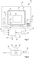
- Fig. 7 shows an example of a measuring arrangement 20 according to an embodiment of the invention for determining a leakage rate of a housing 22 for receiving a device 24 for satellites and space applications.
- a housing 22, which is designed to be hermetically sealed, has a device 24 in an interior volume 8.
- This device 24 may for example be an electronic assembly such as an amplifier or frequency converter, but also any other functional assembly for which a hermetically sealed housing 22 may be necessary.
- the electronic assembly in the form of a printed circuit board 14 (see Fig. 2 ) realized with dimensions in the centimeter range with electronic components applied thereto be.
- a pressure sensor 26 is arranged, which may be embodied for example in MEMS technology.
- This pressure sensor 26 is configured to measure an internal pressure in the internal volume 8 of the housing 22. Furthermore, a temperature sensor 28 is arranged in the inner volume 8 of the housing 22, which is configured to detect an inner temperature in the inner volume 8, ie in particular to measure, and to generate an output signal 44 of the temperature sensor 28.
- the measuring arrangement 20 furthermore has a hermetically sealable chamber 30. In an inner region of the chamber 30, the housing 22, the device 24, the pressure sensor 26, the temperature sensor 28 and a chamber pressure sensor 32 are arranged. The chamber pressure sensor 32 is configured to provide with an output signal 46 a reference signal for adjustment of an output signal 42 of the pressure sensor 26.
- the chamber 30 has a receiving device 34.
- the receiving device 34 may further comprise heating elements or cooling elements (not shown).
- the chamber 30 further includes a temperature adjusting device 36 configured to adjust the temperature within the housing 22. This setting can be done manually, for example, by externally accessible adjustment devices 38.
- the chamber 30 further comprises a pressure adjusting device 40, which serves to set a chamber internal pressure.
- an evaluation unit 48 is arranged, which is designed based on the output signals 42, 44 of the pressure sensor 26 and the temperature sensor 28 and based on measurement times 50 to determine a leakage rate 52.
- the measuring times 50 are provided by a timing device 54.
- Timing device 54 is configured to detect measurement times 50 at which the corresponding pressure measurements and temperature measurements take place via pressure sensor 26 and temperature sensor 28. By means of the measuring times 50, for example, a measurement duration of the measurement can be determined.
- a constant current source 60 which is part of the pressure sensor 26 (see FIG Fig. 7 ) can be.
- a current source temperature sensor 62 is attached to the constant current source 60.
- An output signal 64 of the current source temperature sensor 62 may, for example, an evaluation unit 48 (see Fig. 7 ) are supplied to make a computational correction of a temperature-induced error of the constant current source 60.
- the constant current source 60 is configured to output a constant current 66.
- the constant current source itself is implemented in terms of hardware such that a set current is temperature-independent and temperature compensation takes place in the constant current source itself.
- Fig. 9 shows a method 100 according to an embodiment of the invention for determining a leakage rate of a gas in a housing for receiving an electrical device for use in space.
- a pressure sensor is provided in the housing.
- a temperature sensor is provided in a following step 120.
- a timing device is provided in order to take into account heat-related or temperature-induced errors of the pressure sensor.
- a temperature coefficient of the pressure sensor is determined in a step 140.
- a temperature coefficient of the constant current source is determined in a step 150.
- a closure of the housing takes place.
- the leakage rate of the housing is determined by a Evaluation unit based on the pressure change, the temperature change, the temperature coefficient of the pressure sensor, the temperature coefficient of the constant current source and the determined measurement times.
- the consideration of the temperature coefficients of the Pressure sensor and / or the temperature coefficient of the constant current source is optional and can serve to improve the accuracy of the calculation of the leakage rate.
- Fig. 10 shows by way of example a method 300 according to an embodiment of the invention for determining a temperature coefficient of a pressure sensor.
- the method 300 first includes, in step 310, setting a time constant pressure in one.
- step 320 a temperature in the housing is changed.
- step 330 an output voltage change is detected at the pressure sensor.
- step 340 the temperature coefficient of the pressure sensor is calculated based on the output voltage change and the corresponding temperature in the housing.
- a pressure-temperature characteristic is determined, which represents a mutual dependence of temperature and pressure in the housing.
- Fig. 11 shows by way of example a method 400 according to an embodiment of the invention for determining a temperature coefficient of a constant current source.
- the method 400 includes, at step 410, providing a current source temperature sensor to the constant current source such that the current source temperature sensor can measure a temperature of the constant current source.
- a current measuring device for measuring a current intensity of the constant current source.
- This may be, for example, a conventional ammeter or ammeter which may be connected in series with the constant current source.
- a temperature of the constant current source is changed. This can for example be done by a receiving device 34 (see Fig. 1 ) is specifically tempered for a device and thus also takes place a temperature control of the constant current source.
- step 440 a change in the current intensity of the constant current source resulting from the changed temperature is detected with the current measuring device. From the respective measured temperatures and currents, a temperature coefficient of the constant current source is determined in step 450 based on the change in the temperature and on the change of the current.
Landscapes
- Physics & Mathematics (AREA)
- General Physics & Mathematics (AREA)
- Chemical & Material Sciences (AREA)
- Analytical Chemistry (AREA)
- Measuring Fluid Pressure (AREA)
- Examining Or Testing Airtightness (AREA)
Priority Applications (1)
| Application Number | Priority Date | Filing Date | Title |
|---|---|---|---|
| PL13836226T PL2932221T3 (pl) | 2012-12-13 | 2013-12-13 | Sposób badania szczelności obudowy |
Applications Claiming Priority (3)
| Application Number | Priority Date | Filing Date | Title |
|---|---|---|---|
| DE102012024346 | 2012-12-13 | ||
| DE102013020388.0A DE102013020388A1 (de) | 2012-12-13 | 2013-12-10 | Verfahren zur Dichteprüfung eines Gehäuses |
| PCT/DE2013/000777 WO2014090220A2 (de) | 2012-12-13 | 2013-12-13 | Verfahren zur dichteprüfung eines gehäuses |
Publications (2)
| Publication Number | Publication Date |
|---|---|
| EP2932221A2 EP2932221A2 (de) | 2015-10-21 |
| EP2932221B1 true EP2932221B1 (de) | 2017-08-30 |
Family
ID=50241038
Family Applications (1)
| Application Number | Title | Priority Date | Filing Date |
|---|---|---|---|
| EP13836226.4A Not-in-force EP2932221B1 (de) | 2012-12-13 | 2013-12-13 | Verfahren zur dichteprüfung eines gehäuses |
Country Status (9)
| Country | Link |
|---|---|
| US (1) | US9719880B2 (pl) |
| EP (1) | EP2932221B1 (pl) |
| JP (1) | JP2014119456A (pl) |
| DE (1) | DE102013020388A1 (pl) |
| DK (1) | DK2932221T3 (pl) |
| ES (1) | ES2649716T3 (pl) |
| PL (1) | PL2932221T3 (pl) |
| PT (1) | PT2932221T (pl) |
| WO (1) | WO2014090220A2 (pl) |
Families Citing this family (13)
| Publication number | Priority date | Publication date | Assignee | Title |
|---|---|---|---|---|
| DE102014216457B4 (de) * | 2014-08-19 | 2023-11-16 | Bayerische Motoren Werke Aktiengesellschaft | Vorrichtung und Verfahren zur Temperaturkompensation beim Dichtheitsprüfen von Bauteilen |
| CN107091717B (zh) * | 2016-02-18 | 2021-01-12 | 太阳能安吉科技有限公司 | 用于气密性测试的方法和设备、通风塞 |
| JP6833024B2 (ja) * | 2016-10-12 | 2021-02-24 | 華為技術有限公司Huawei Technologies Co.,Ltd. | 密封性能検査方法、装置、および記憶媒体 |
| US10900863B2 (en) | 2017-08-10 | 2021-01-26 | Panoramic Power Ltd. | Identification of air leaks in a compressed air system using a plurality of current measurement sensors |
| DE102017214846A1 (de) | 2017-08-24 | 2019-02-28 | Infineon Technologies Ag | Gehäustes MEMS Bauteil mit Störgrößenkompensation |
| EP3502644B1 (en) * | 2017-12-19 | 2021-11-03 | Michele Tognetti | Leak testing methods for tanks |
| FR3079032B1 (fr) * | 2018-03-19 | 2020-09-04 | Tyco Electronics France Sas | Boîtier électrique et procédé pour tester l’étanchéité du boîtier électrique |
| CN109406073B (zh) * | 2018-11-09 | 2024-04-16 | 北京新风航天装备有限公司 | 一种铝合金铸件壳体气密性检测的装置 |
| US11847311B2 (en) * | 2019-05-22 | 2023-12-19 | Apple Inc. | Characterization of a venting state or other system parameter that affects the characterization of a force applied to a device |
| CN116296128A (zh) * | 2021-12-21 | 2023-06-23 | 上海神奕医疗科技有限公司 | 密封性测定装置 |
| DE102022201170A1 (de) | 2022-02-03 | 2023-01-19 | Vitesco Technologies GmbH | Gehäusevorrichtung und Verfahren zum Überprüfen der Dichtheit eines Gehäuses einer Gehäusevorrichtung |
| DE102022106099A1 (de) | 2022-03-16 | 2023-09-21 | Steute Technologies Gmbh & Co. Kg | Fußschalter mit einem Gehäuse und Verfahren zur Dichtheitsüberprüfung eines Gehäuses |
| CN114812968A (zh) * | 2022-04-21 | 2022-07-29 | 北京化工大学 | 一种实现热密封泄漏率精确测量系统与方法 |
Citations (5)
| Publication number | Priority date | Publication date | Assignee | Title |
|---|---|---|---|---|
| US5214957A (en) * | 1992-03-31 | 1993-06-01 | Hydro-Quebec | Integrity and leak rate testing of a hermetic building |
| DE4335838C1 (de) * | 1993-10-20 | 1995-02-02 | Ifas Ingges | Vorrichtung zur elektronischen Bestimmung von Drücken und Druckdifferenzen in einem fluiden Medium |
| US20110153232A1 (en) * | 2009-12-17 | 2011-06-23 | Mitsubishi Electric Corporation | Gas pressure monitoring system and gas-insulated electric apparatus |
| US8201438B1 (en) * | 2008-04-18 | 2012-06-19 | Sandia Corporation | Detection of gas leakage |
| WO2012081537A1 (ja) * | 2010-12-14 | 2012-06-21 | 株式会社エイムテック | 差圧計測方法及び装置 |
Family Cites Families (27)
| Publication number | Priority date | Publication date | Assignee | Title |
|---|---|---|---|---|
| RU1772638C (ru) * | 1976-09-23 | 1992-10-30 | Головное конструкторское бюро научно-производственного объединения "Энергия" им.акад.С.П.Королева | Устройство дл испытани на герметичность |
| JPS579714Y2 (pl) * | 1977-12-02 | 1982-02-24 | ||
| US4920785A (en) * | 1984-06-21 | 1990-05-01 | Web Technology, Inc. | Hermeticity testing method and system |
| US4608866A (en) * | 1985-03-13 | 1986-09-02 | Martin Marietta Corporation | Small component helium leak detector |
| JPH0285739A (ja) * | 1988-09-22 | 1990-03-27 | Toyo Seikan Kaisha Ltd | 密封容器の内圧検出方法 |
| JP2530272Y2 (ja) * | 1990-07-30 | 1997-03-26 | アスコ株式会社 | 電子部品用パッケージの封止性検知装置 |
| DE4102923A1 (de) | 1991-01-31 | 1992-08-06 | Uwatec Ag | Luftdruckmessgeraet |
| JPH10206273A (ja) * | 1997-01-21 | 1998-08-07 | Toyota Motor Corp | 角速度センサの気密性確認方法及び装置 |
| JPH1151802A (ja) * | 1997-07-31 | 1999-02-26 | River Eletec Kk | 圧電素子用パッケージの気密検査方法 |
| FR2770295B1 (fr) * | 1997-10-23 | 1999-11-26 | Gec Alsthom T & D Sa | Capteur de densite pour surveiller un taux de fuite d'une enveloppe d'appareillage electrique avec une fiabilite amelioree |
| JP2004157055A (ja) * | 2002-11-07 | 2004-06-03 | Yamatake Corp | エアリーク量検出装置及びこれを備えた流量計 |
| US6931938B2 (en) * | 2002-12-16 | 2005-08-23 | Jeffrey G. Knirck | Measuring pressure exerted by a rigid surface |
| JP2004219386A (ja) * | 2003-01-17 | 2004-08-05 | Vacuum Products Kk | 2種混合気体の濃度測定装置 |
| EP1533270A1 (fr) * | 2003-11-21 | 2005-05-25 | Asulab S.A. | Procédé de contrôle de l'herméticité d'une cavité close d'un composant micrométrique, et composant micrométrique pour sa mise en oeuvre |
| US7087451B2 (en) * | 2004-03-24 | 2006-08-08 | Intel Corporation | Microfabricated hot wire vacuum sensor |
| EP1831664B1 (en) | 2004-12-07 | 2012-01-11 | Fraunhofer-Gesellschaft zur Förderung der angewandten Forschung e.V. | Method for testing the leakage rate of vacuum capsulated devices |
| US7600525B2 (en) | 2005-09-14 | 2009-10-13 | Honeywell International Inc. | Leak detection and isolation for segmented inflatable structures |
| US8131376B1 (en) * | 2007-09-11 | 2012-03-06 | Second Sight Medical Products, Inc. | Method of inspection of materials for defects |
| EP2213997B1 (en) * | 2007-10-29 | 2013-07-03 | Toyo Seikan Kaisha, Ltd. | Method and apparatus for inspecting pinhole in synthetic resin bottle |
| US8267486B2 (en) * | 2008-12-23 | 2012-09-18 | Analog Devices, Inc. | Apparatus and method of detecting microchip hermeticity |
| US8316718B2 (en) * | 2010-08-23 | 2012-11-27 | Freescale Semiconductor, Inc. | MEMS pressure sensor device and method of fabricating same |
| US8448498B1 (en) * | 2010-08-27 | 2013-05-28 | United States Of America As Represented By The Administrator Of The National Aeronautics And Space Administration | Hermetic seal leak detection apparatus |
| US20120085750A1 (en) | 2010-10-08 | 2012-04-12 | Dyconex Ag | Covering Device for an Organic Substrate, Substrate with a Covering Device, and Method for Producing a Covering Device |
| US8436738B2 (en) * | 2010-11-03 | 2013-05-07 | General Electric Company | Method and apparatus for appliance gas leak detection |
| DE102010056431B4 (de) | 2010-12-28 | 2012-09-27 | Epcos Ag | Bauelement und Verfahren zum Herstellen eines Bauelements |
| JP5749510B2 (ja) * | 2011-02-09 | 2015-07-15 | 株式会社アルバック | 密閉型デバイス |
| US9097609B1 (en) * | 2013-04-30 | 2015-08-04 | The United States Of America As Represented By The Administrator Of The National Aeronautics And Space Administration | Hermetic seal leak detection apparatus with variable size test chamber |
-
2013
- 2013-12-10 DE DE102013020388.0A patent/DE102013020388A1/de not_active Withdrawn
- 2013-12-12 JP JP2013257391A patent/JP2014119456A/ja active Pending
- 2013-12-12 US US14/104,535 patent/US9719880B2/en not_active Expired - Fee Related
- 2013-12-13 DK DK13836226.4T patent/DK2932221T3/en active
- 2013-12-13 WO PCT/DE2013/000777 patent/WO2014090220A2/de not_active Ceased
- 2013-12-13 PT PT138362264T patent/PT2932221T/pt unknown
- 2013-12-13 EP EP13836226.4A patent/EP2932221B1/de not_active Not-in-force
- 2013-12-13 PL PL13836226T patent/PL2932221T3/pl unknown
- 2013-12-13 ES ES13836226.4T patent/ES2649716T3/es active Active
Patent Citations (5)
| Publication number | Priority date | Publication date | Assignee | Title |
|---|---|---|---|---|
| US5214957A (en) * | 1992-03-31 | 1993-06-01 | Hydro-Quebec | Integrity and leak rate testing of a hermetic building |
| DE4335838C1 (de) * | 1993-10-20 | 1995-02-02 | Ifas Ingges | Vorrichtung zur elektronischen Bestimmung von Drücken und Druckdifferenzen in einem fluiden Medium |
| US8201438B1 (en) * | 2008-04-18 | 2012-06-19 | Sandia Corporation | Detection of gas leakage |
| US20110153232A1 (en) * | 2009-12-17 | 2011-06-23 | Mitsubishi Electric Corporation | Gas pressure monitoring system and gas-insulated electric apparatus |
| WO2012081537A1 (ja) * | 2010-12-14 | 2012-06-21 | 株式会社エイムテック | 差圧計測方法及び装置 |
Also Published As
| Publication number | Publication date |
|---|---|
| DE102013020388A1 (de) | 2014-06-18 |
| PT2932221T (pt) | 2017-11-28 |
| DK2932221T3 (en) | 2017-12-11 |
| US9719880B2 (en) | 2017-08-01 |
| ES2649716T3 (es) | 2018-01-15 |
| EP2932221A2 (de) | 2015-10-21 |
| JP2014119456A (ja) | 2014-06-30 |
| PL2932221T3 (pl) | 2018-03-30 |
| US20140165708A1 (en) | 2014-06-19 |
| WO2014090220A2 (de) | 2014-06-19 |
| WO2014090220A3 (de) | 2014-08-07 |
Similar Documents
| Publication | Publication Date | Title |
|---|---|---|
| DE102013020388A1 (de) | Verfahren zur Dichteprüfung eines Gehäuses | |
| EP1269135A1 (de) | Drucksensormodul | |
| DE102009026744B4 (de) | Verfahren zur Dichtheitsprüfung von Bauteilen | |
| DE112007000433T5 (de) | Kapazitive Abstandsmessung bei Halbleiterverarbeitungswerkzeugen | |
| DE102014207480A1 (de) | Vorrichtung zum Erfassen eines Parameters eines Gases, Verfahren zum Betreiben einer derartigen Vorrichtung und Messsystem zum Bestimmen eines Parameters eines Gases | |
| DE102020203910B3 (de) | Verfahren zum Detektieren einer Verunreinigung eines MEMS-Sensorelements | |
| DE102007062713A1 (de) | Drucksensor und Verfahren zu dessen Kalibrierung | |
| WO2004111594A1 (de) | Drucksensor mit feuchteschutz | |
| DE102008054428A1 (de) | Aufbau eines Drucksensors | |
| DE112018007013T5 (de) | Sensorvorrichtung | |
| Scandurra et al. | A new approach to DC removal in high gain, low noise voltage amplifiers | |
| DE102007057694B4 (de) | Leckageerkennung bei einem Gehäuse eines elektronischen Steuergeräts | |
| EP1397656B1 (de) | Verfahren und vorrichtung zum testen oder kalibrieren eines drucksensors an einem wafer | |
| DE102014119400A1 (de) | Druckwandler und Verfahren zum Betreiben eines solchen | |
| EP1325295B1 (de) | Druckmesszelle | |
| DE102015214292A1 (de) | Vorrichtung und Verfahren zur thermo-optischen Untersuchung von Proben | |
| EP1279941A2 (de) | Verfahren zur Dichtigkeitsprüfung von kapazitiven Sensoren | |
| DE10339319B4 (de) | Edelgasgefülltes Sensorelement für optische Sensoren | |
| DE102021119081A1 (de) | Druckmittler mit Überwachungsfunktion | |
| EP1726936A1 (de) | Vorrichtung und Verfahren zum Kalibrieren von Dehnungsmesschaltungen | |
| DE102016200267A1 (de) | Mikromechanische Vorrichtung und Verfahren zum Detektieren eines Gases | |
| DE102011085652A1 (de) | Vorrichtung zur Erfassung eines Drucks eines fluiden Mediums | |
| DE102009045158A1 (de) | Sensoranordnung und Verfahren zur Herstellung einer Sensoranordnung | |
| DE102022112470B4 (de) | Verfahren und Vorrichtung zur aktiven Stabilisierung der Gasbrechzahl, respektive der Gasdichte, in einer abgeschlossenen Messkammer | |
| DE102019126024A1 (de) | Verfahren zum Testen eines Gassensors |
Legal Events
| Date | Code | Title | Description |
|---|---|---|---|
| PUAI | Public reference made under article 153(3) epc to a published international application that has entered the european phase |
Free format text: ORIGINAL CODE: 0009012 |
|
| 17P | Request for examination filed |
Effective date: 20150701 |
|
| AK | Designated contracting states |
Kind code of ref document: A2 Designated state(s): AL AT BE BG CH CY CZ DE DK EE ES FI FR GB GR HR HU IE IS IT LI LT LU LV MC MK MT NL NO PL PT RO RS SE SI SK SM TR |
|
| AX | Request for extension of the european patent |
Extension state: BA ME |
|
| DAX | Request for extension of the european patent (deleted) | ||
| 17Q | First examination report despatched |
Effective date: 20160722 |
|
| STAA | Information on the status of an ep patent application or granted ep patent |
Free format text: STATUS: EXAMINATION IS IN PROGRESS |
|
| REG | Reference to a national code |
Ref country code: DE Ref legal event code: R079 Ref document number: 502013008233 Country of ref document: DE Free format text: PREVIOUS MAIN CLASS: G01L0019040000 Ipc: G01L0009060000 |
|
| RIC1 | Information provided on ipc code assigned before grant |
Ipc: G01M 3/32 20060101ALI20170317BHEP Ipc: G01L 9/06 20060101AFI20170317BHEP Ipc: G01L 19/00 20060101ALI20170317BHEP |
|
| GRAP | Despatch of communication of intention to grant a patent |
Free format text: ORIGINAL CODE: EPIDOSNIGR1 |
|
| STAA | Information on the status of an ep patent application or granted ep patent |
Free format text: STATUS: GRANT OF PATENT IS INTENDED |
|
| INTG | Intention to grant announced |
Effective date: 20170428 |
|
| GRAS | Grant fee paid |
Free format text: ORIGINAL CODE: EPIDOSNIGR3 |
|
| GRAA | (expected) grant |
Free format text: ORIGINAL CODE: 0009210 |
|
| STAA | Information on the status of an ep patent application or granted ep patent |
Free format text: STATUS: THE PATENT HAS BEEN GRANTED |
|
| AK | Designated contracting states |
Kind code of ref document: B1 Designated state(s): AL AT BE BG CH CY CZ DE DK EE ES FI FR GB GR HR HU IE IS IT LI LT LU LV MC MK MT NL NO PL PT RO RS SE SI SK SM TR |
|
| REG | Reference to a national code |
Ref country code: GB Ref legal event code: FG4D Free format text: NOT ENGLISH |
|
| REG | Reference to a national code |
Ref country code: CH Ref legal event code: EP |
|
| REG | Reference to a national code |
Ref country code: AT Ref legal event code: REF Ref document number: 924019 Country of ref document: AT Kind code of ref document: T Effective date: 20170915 |
|
| REG | Reference to a national code |
Ref country code: IE Ref legal event code: FG4D Free format text: LANGUAGE OF EP DOCUMENT: GERMAN |
|
| REG | Reference to a national code |
Ref country code: DE Ref legal event code: R096 Ref document number: 502013008233 Country of ref document: DE |
|
| REG | Reference to a national code |
Ref country code: PT Ref legal event code: SC4A Ref document number: 2932221 Country of ref document: PT Date of ref document: 20171128 Kind code of ref document: T Free format text: AVAILABILITY OF NATIONAL TRANSLATION Effective date: 20171121 |
|
| REG | Reference to a national code |
Ref country code: DK Ref legal event code: T3 Effective date: 20171206 |
|
| REG | Reference to a national code |
Ref country code: NL Ref legal event code: FP |
|
| REG | Reference to a national code |
Ref country code: FR Ref legal event code: PLFP Year of fee payment: 5 |
|
| REG | Reference to a national code |
Ref country code: LT Ref legal event code: MG4D |
|
| REG | Reference to a national code |
Ref country code: ES Ref legal event code: FG2A Ref document number: 2649716 Country of ref document: ES Kind code of ref document: T3 Effective date: 20180115 |
|
| PG25 | Lapsed in a contracting state [announced via postgrant information from national office to epo] |
Ref country code: SE Free format text: LAPSE BECAUSE OF FAILURE TO SUBMIT A TRANSLATION OF THE DESCRIPTION OR TO PAY THE FEE WITHIN THE PRESCRIBED TIME-LIMIT Effective date: 20170830 Ref country code: FI Free format text: LAPSE BECAUSE OF FAILURE TO SUBMIT A TRANSLATION OF THE DESCRIPTION OR TO PAY THE FEE WITHIN THE PRESCRIBED TIME-LIMIT Effective date: 20170830 Ref country code: LT Free format text: LAPSE BECAUSE OF FAILURE TO SUBMIT A TRANSLATION OF THE DESCRIPTION OR TO PAY THE FEE WITHIN THE PRESCRIBED TIME-LIMIT Effective date: 20170830 Ref country code: HR Free format text: LAPSE BECAUSE OF FAILURE TO SUBMIT A TRANSLATION OF THE DESCRIPTION OR TO PAY THE FEE WITHIN THE PRESCRIBED TIME-LIMIT Effective date: 20170830 |
|
| PGFP | Annual fee paid to national office [announced via postgrant information from national office to epo] |
Ref country code: DK Payment date: 20171215 Year of fee payment: 5 Ref country code: NL Payment date: 20171219 Year of fee payment: 5 |
|
| REG | Reference to a national code |
Ref country code: NO Ref legal event code: T2 Effective date: 20170830 |
|
| PG25 | Lapsed in a contracting state [announced via postgrant information from national office to epo] |
Ref country code: LV Free format text: LAPSE BECAUSE OF FAILURE TO SUBMIT A TRANSLATION OF THE DESCRIPTION OR TO PAY THE FEE WITHIN THE PRESCRIBED TIME-LIMIT Effective date: 20170830 Ref country code: BG Free format text: LAPSE BECAUSE OF FAILURE TO SUBMIT A TRANSLATION OF THE DESCRIPTION OR TO PAY THE FEE WITHIN THE PRESCRIBED TIME-LIMIT Effective date: 20171130 Ref country code: IS Free format text: LAPSE BECAUSE OF FAILURE TO SUBMIT A TRANSLATION OF THE DESCRIPTION OR TO PAY THE FEE WITHIN THE PRESCRIBED TIME-LIMIT Effective date: 20171230 Ref country code: GR Free format text: LAPSE BECAUSE OF FAILURE TO SUBMIT A TRANSLATION OF THE DESCRIPTION OR TO PAY THE FEE WITHIN THE PRESCRIBED TIME-LIMIT Effective date: 20171201 Ref country code: RS Free format text: LAPSE BECAUSE OF FAILURE TO SUBMIT A TRANSLATION OF THE DESCRIPTION OR TO PAY THE FEE WITHIN THE PRESCRIBED TIME-LIMIT Effective date: 20170830 |
|
| PGFP | Annual fee paid to national office [announced via postgrant information from national office to epo] |
Ref country code: GB Payment date: 20171221 Year of fee payment: 5 Ref country code: CH Payment date: 20171220 Year of fee payment: 5 Ref country code: BE Payment date: 20171219 Year of fee payment: 5 |
|
| PG25 | Lapsed in a contracting state [announced via postgrant information from national office to epo] |
Ref country code: RO Free format text: LAPSE BECAUSE OF FAILURE TO SUBMIT A TRANSLATION OF THE DESCRIPTION OR TO PAY THE FEE WITHIN THE PRESCRIBED TIME-LIMIT Effective date: 20170830 |
|
| PGFP | Annual fee paid to national office [announced via postgrant information from national office to epo] |
Ref country code: NO Payment date: 20171221 Year of fee payment: 5 Ref country code: ES Payment date: 20180124 Year of fee payment: 5 |
|
| PG25 | Lapsed in a contracting state [announced via postgrant information from national office to epo] |
Ref country code: SK Free format text: LAPSE BECAUSE OF FAILURE TO SUBMIT A TRANSLATION OF THE DESCRIPTION OR TO PAY THE FEE WITHIN THE PRESCRIBED TIME-LIMIT Effective date: 20170830 Ref country code: EE Free format text: LAPSE BECAUSE OF FAILURE TO SUBMIT A TRANSLATION OF THE DESCRIPTION OR TO PAY THE FEE WITHIN THE PRESCRIBED TIME-LIMIT Effective date: 20170830 Ref country code: SM Free format text: LAPSE BECAUSE OF FAILURE TO SUBMIT A TRANSLATION OF THE DESCRIPTION OR TO PAY THE FEE WITHIN THE PRESCRIBED TIME-LIMIT Effective date: 20170830 |
|
| PGFP | Annual fee paid to national office [announced via postgrant information from national office to epo] |
Ref country code: IT Payment date: 20171229 Year of fee payment: 5 |
|
| REG | Reference to a national code |
Ref country code: DE Ref legal event code: R097 Ref document number: 502013008233 Country of ref document: DE |
|
| PLBE | No opposition filed within time limit |
Free format text: ORIGINAL CODE: 0009261 |
|
| STAA | Information on the status of an ep patent application or granted ep patent |
Free format text: STATUS: NO OPPOSITION FILED WITHIN TIME LIMIT |
|
| 26N | No opposition filed |
Effective date: 20180531 |
|
| PG25 | Lapsed in a contracting state [announced via postgrant information from national office to epo] |
Ref country code: SI Free format text: LAPSE BECAUSE OF FAILURE TO SUBMIT A TRANSLATION OF THE DESCRIPTION OR TO PAY THE FEE WITHIN THE PRESCRIBED TIME-LIMIT Effective date: 20170830 |
|
| REG | Reference to a national code |
Ref country code: IE Ref legal event code: MM4A |
|
| PG25 | Lapsed in a contracting state [announced via postgrant information from national office to epo] |
Ref country code: LU Free format text: LAPSE BECAUSE OF NON-PAYMENT OF DUE FEES Effective date: 20171213 Ref country code: MT Free format text: LAPSE BECAUSE OF FAILURE TO SUBMIT A TRANSLATION OF THE DESCRIPTION OR TO PAY THE FEE WITHIN THE PRESCRIBED TIME-LIMIT Effective date: 20170830 |
|
| PG25 | Lapsed in a contracting state [announced via postgrant information from national office to epo] |
Ref country code: IE Free format text: LAPSE BECAUSE OF NON-PAYMENT OF DUE FEES Effective date: 20171213 |
|
| PGFP | Annual fee paid to national office [announced via postgrant information from national office to epo] |
Ref country code: CZ Payment date: 20181212 Year of fee payment: 6 Ref country code: PT Payment date: 20181210 Year of fee payment: 6 |
|
| PGFP | Annual fee paid to national office [announced via postgrant information from national office to epo] |
Ref country code: PL Payment date: 20181204 Year of fee payment: 6 |
|
| PG25 | Lapsed in a contracting state [announced via postgrant information from national office to epo] |
Ref country code: HU Free format text: LAPSE BECAUSE OF FAILURE TO SUBMIT A TRANSLATION OF THE DESCRIPTION OR TO PAY THE FEE WITHIN THE PRESCRIBED TIME-LIMIT; INVALID AB INITIO Effective date: 20131213 Ref country code: MC Free format text: LAPSE BECAUSE OF FAILURE TO SUBMIT A TRANSLATION OF THE DESCRIPTION OR TO PAY THE FEE WITHIN THE PRESCRIBED TIME-LIMIT Effective date: 20170830 |
|
| REG | Reference to a national code |
Ref country code: NO Ref legal event code: MMEP |
|
| REG | Reference to a national code |
Ref country code: DK Ref legal event code: EBP Effective date: 20181231 |
|
| REG | Reference to a national code |
Ref country code: CH Ref legal event code: PL |
|
| REG | Reference to a national code |
Ref country code: NL Ref legal event code: MM Effective date: 20190101 |
|
| GBPC | Gb: european patent ceased through non-payment of renewal fee |
Effective date: 20181213 |
|
| PG25 | Lapsed in a contracting state [announced via postgrant information from national office to epo] |
Ref country code: NL Free format text: LAPSE BECAUSE OF NON-PAYMENT OF DUE FEES Effective date: 20190101 |
|
| REG | Reference to a national code |
Ref country code: BE Ref legal event code: MM Effective date: 20181231 |
|
| PG25 | Lapsed in a contracting state [announced via postgrant information from national office to epo] |
Ref country code: IT Free format text: LAPSE BECAUSE OF NON-PAYMENT OF DUE FEES Effective date: 20181213 Ref country code: CY Free format text: LAPSE BECAUSE OF FAILURE TO SUBMIT A TRANSLATION OF THE DESCRIPTION OR TO PAY THE FEE WITHIN THE PRESCRIBED TIME-LIMIT Effective date: 20170830 Ref country code: NO Free format text: LAPSE BECAUSE OF NON-PAYMENT OF DUE FEES Effective date: 20181231 |
|
| PG25 | Lapsed in a contracting state [announced via postgrant information from national office to epo] |
Ref country code: BE Free format text: LAPSE BECAUSE OF NON-PAYMENT OF DUE FEES Effective date: 20181231 Ref country code: MK Free format text: LAPSE BECAUSE OF FAILURE TO SUBMIT A TRANSLATION OF THE DESCRIPTION OR TO PAY THE FEE WITHIN THE PRESCRIBED TIME-LIMIT Effective date: 20170830 |
|
| PG25 | Lapsed in a contracting state [announced via postgrant information from national office to epo] |
Ref country code: CH Free format text: LAPSE BECAUSE OF NON-PAYMENT OF DUE FEES Effective date: 20181231 Ref country code: LI Free format text: LAPSE BECAUSE OF NON-PAYMENT OF DUE FEES Effective date: 20181231 Ref country code: GB Free format text: LAPSE BECAUSE OF NON-PAYMENT OF DUE FEES Effective date: 20181213 |
|
| PG25 | Lapsed in a contracting state [announced via postgrant information from national office to epo] |
Ref country code: DK Free format text: LAPSE BECAUSE OF NON-PAYMENT OF DUE FEES Effective date: 20181231 |
|
| REG | Reference to a national code |
Ref country code: ES Ref legal event code: FD2A Effective date: 20200203 |
|
| REG | Reference to a national code |
Ref country code: AT Ref legal event code: MM01 Ref document number: 924019 Country of ref document: AT Kind code of ref document: T Effective date: 20181213 |
|
| PG25 | Lapsed in a contracting state [announced via postgrant information from national office to epo] |
Ref country code: TR Free format text: LAPSE BECAUSE OF FAILURE TO SUBMIT A TRANSLATION OF THE DESCRIPTION OR TO PAY THE FEE WITHIN THE PRESCRIBED TIME-LIMIT Effective date: 20170830 |
|
| PG25 | Lapsed in a contracting state [announced via postgrant information from national office to epo] |
Ref country code: ES Free format text: LAPSE BECAUSE OF NON-PAYMENT OF DUE FEES Effective date: 20181214 Ref country code: AT Free format text: LAPSE BECAUSE OF NON-PAYMENT OF DUE FEES Effective date: 20181213 |
|
| PG25 | Lapsed in a contracting state [announced via postgrant information from national office to epo] |
Ref country code: CZ Free format text: LAPSE BECAUSE OF NON-PAYMENT OF DUE FEES Effective date: 20191213 Ref country code: AL Free format text: LAPSE BECAUSE OF FAILURE TO SUBMIT A TRANSLATION OF THE DESCRIPTION OR TO PAY THE FEE WITHIN THE PRESCRIBED TIME-LIMIT Effective date: 20170830 |
|
| PG25 | Lapsed in a contracting state [announced via postgrant information from national office to epo] |
Ref country code: PT Free format text: LAPSE BECAUSE OF NON-PAYMENT OF DUE FEES Effective date: 20200716 |
|
| PGFP | Annual fee paid to national office [announced via postgrant information from national office to epo] |
Ref country code: FR Payment date: 20211224 Year of fee payment: 9 Ref country code: DE Payment date: 20211210 Year of fee payment: 9 |
|
| PG25 | Lapsed in a contracting state [announced via postgrant information from national office to epo] |
Ref country code: PL Free format text: LAPSE BECAUSE OF NON-PAYMENT OF DUE FEES Effective date: 20191213 |
|
| REG | Reference to a national code |
Ref country code: DE Ref legal event code: R119 Ref document number: 502013008233 Country of ref document: DE |
|
| PG25 | Lapsed in a contracting state [announced via postgrant information from national office to epo] |
Ref country code: DE Free format text: LAPSE BECAUSE OF NON-PAYMENT OF DUE FEES Effective date: 20230701 |
|
| PG25 | Lapsed in a contracting state [announced via postgrant information from national office to epo] |
Ref country code: FR Free format text: LAPSE BECAUSE OF NON-PAYMENT OF DUE FEES Effective date: 20221231 |