EP2931940B1 - Enamel coating comprising anisotropic particles and cooking item provided with such a coating - Google Patents
Enamel coating comprising anisotropic particles and cooking item provided with such a coating Download PDFInfo
- Publication number
- EP2931940B1 EP2931940B1 EP13815080.0A EP13815080A EP2931940B1 EP 2931940 B1 EP2931940 B1 EP 2931940B1 EP 13815080 A EP13815080 A EP 13815080A EP 2931940 B1 EP2931940 B1 EP 2931940B1
- Authority
- EP
- European Patent Office
- Prior art keywords
- particles
- article
- enamel
- support
- layer
- Prior art date
- Legal status (The legal status is an assumption and is not a legal conclusion. Google has not performed a legal analysis and makes no representation as to the accuracy of the status listed.)
- Active
Links
- 239000002245 particle Substances 0.000 title claims description 127
- 238000000576 coating method Methods 0.000 title description 45
- 239000011248 coating agent Substances 0.000 title description 42
- 239000002320 enamel (paints) Substances 0.000 title description 21
- 238000010411 cooking Methods 0.000 title description 6
- 210000003298 dental enamel Anatomy 0.000 claims description 98
- XEEYBQQBJWHFJM-UHFFFAOYSA-N Iron Chemical compound [Fe] XEEYBQQBJWHFJM-UHFFFAOYSA-N 0.000 claims description 44
- 239000000203 mixture Substances 0.000 claims description 42
- 229910052751 metal Inorganic materials 0.000 claims description 23
- 239000002184 metal Substances 0.000 claims description 23
- 239000011253 protective coating Substances 0.000 claims description 23
- 230000005291 magnetic effect Effects 0.000 claims description 22
- 229910052742 iron Inorganic materials 0.000 claims description 20
- 230000005415 magnetization Effects 0.000 claims description 16
- 230000005294 ferromagnetic effect Effects 0.000 claims description 13
- 238000010438 heat treatment Methods 0.000 claims description 13
- 238000000034 method Methods 0.000 claims description 12
- 238000005507 spraying Methods 0.000 claims description 10
- 238000001035 drying Methods 0.000 claims description 9
- 239000000463 material Substances 0.000 claims description 9
- 235000021168 barbecue Nutrition 0.000 claims description 8
- 238000010304 firing Methods 0.000 claims description 7
- 150000002739 metals Chemical class 0.000 claims description 5
- 239000000919 ceramic Substances 0.000 claims description 4
- 235000013305 food Nutrition 0.000 claims description 4
- 238000005034 decoration Methods 0.000 claims description 3
- 238000002360 preparation method Methods 0.000 claims description 3
- 239000011521 glass Substances 0.000 claims description 2
- 238000002156 mixing Methods 0.000 claims description 2
- 235000013361 beverage Nutrition 0.000 claims 1
- 239000002023 wood Substances 0.000 claims 1
- 239000010410 layer Substances 0.000 description 105
- 229910052782 aluminium Inorganic materials 0.000 description 24
- XAGFODPZIPBFFR-UHFFFAOYSA-N aluminium Chemical compound [Al] XAGFODPZIPBFFR-UHFFFAOYSA-N 0.000 description 23
- 239000002966 varnish Substances 0.000 description 20
- 239000010445 mica Substances 0.000 description 16
- 229910052618 mica group Inorganic materials 0.000 description 16
- 239000000945 filler Substances 0.000 description 14
- 239000004411 aluminium Substances 0.000 description 12
- UQSXHKLRYXJYBZ-UHFFFAOYSA-N Iron oxide Chemical compound [Fe]=O UQSXHKLRYXJYBZ-UHFFFAOYSA-N 0.000 description 10
- 229910000831 Steel Inorganic materials 0.000 description 10
- 239000010959 steel Substances 0.000 description 10
- 239000000049 pigment Substances 0.000 description 9
- 229910001220 stainless steel Inorganic materials 0.000 description 9
- 239000010935 stainless steel Substances 0.000 description 8
- 229910001018 Cast iron Inorganic materials 0.000 description 7
- 230000032798 delamination Effects 0.000 description 7
- 235000000396 iron Nutrition 0.000 description 7
- 238000007650 screen-printing Methods 0.000 description 7
- 239000000758 substrate Substances 0.000 description 7
- 229910000838 Al alloy Inorganic materials 0.000 description 6
- RYGMFSIKBFXOCR-UHFFFAOYSA-N Copper Chemical compound [Cu] RYGMFSIKBFXOCR-UHFFFAOYSA-N 0.000 description 5
- 230000000052 comparative effect Effects 0.000 description 5
- 239000000835 fiber Substances 0.000 description 5
- 238000004519 manufacturing process Methods 0.000 description 5
- 238000005259 measurement Methods 0.000 description 5
- VYPSYNLAJGMNEJ-UHFFFAOYSA-N Silicium dioxide Chemical compound O=[Si]=O VYPSYNLAJGMNEJ-UHFFFAOYSA-N 0.000 description 4
- 229910052802 copper Inorganic materials 0.000 description 4
- 239000010949 copper Substances 0.000 description 4
- 230000002787 reinforcement Effects 0.000 description 4
- XLYOFNOQVPJJNP-UHFFFAOYSA-N water Substances O XLYOFNOQVPJJNP-UHFFFAOYSA-N 0.000 description 4
- 229910000906 Bronze Inorganic materials 0.000 description 3
- KKCBUQHMOMHUOY-UHFFFAOYSA-N Na2O Inorganic materials [O-2].[Na+].[Na+] KKCBUQHMOMHUOY-UHFFFAOYSA-N 0.000 description 3
- KWYUFKZDYYNOTN-UHFFFAOYSA-M Potassium hydroxide Chemical compound [OH-].[K+] KWYUFKZDYYNOTN-UHFFFAOYSA-M 0.000 description 3
- 229910004298 SiO 2 Inorganic materials 0.000 description 3
- 229910045601 alloy Inorganic materials 0.000 description 3
- 239000000956 alloy Substances 0.000 description 3
- KGBXLFKZBHKPEV-UHFFFAOYSA-N boric acid Chemical compound OB(O)O KGBXLFKZBHKPEV-UHFFFAOYSA-N 0.000 description 3
- 239000004327 boric acid Substances 0.000 description 3
- 239000010974 bronze Substances 0.000 description 3
- 239000011247 coating layer Substances 0.000 description 3
- KUNSUQLRTQLHQQ-UHFFFAOYSA-N copper tin Chemical compound [Cu].[Sn] KUNSUQLRTQLHQQ-UHFFFAOYSA-N 0.000 description 3
- 230000000694 effects Effects 0.000 description 3
- 239000000806 elastomer Substances 0.000 description 3
- 229920001971 elastomer Polymers 0.000 description 3
- 238000001878 scanning electron micrograph Methods 0.000 description 3
- 239000002356 single layer Substances 0.000 description 3
- SVTBMSDMJJWYQN-UHFFFAOYSA-N 2-methylpentane-2,4-diol Chemical compound CC(O)CC(C)(C)O SVTBMSDMJJWYQN-UHFFFAOYSA-N 0.000 description 2
- 229910018072 Al 2 O 3 Inorganic materials 0.000 description 2
- 229910001208 Crucible steel Inorganic materials 0.000 description 2
- PXHVJJICTQNCMI-UHFFFAOYSA-N Nickel Chemical compound [Ni] PXHVJJICTQNCMI-UHFFFAOYSA-N 0.000 description 2
- 101150006573 PAN1 gene Proteins 0.000 description 2
- 229910010413 TiO 2 Inorganic materials 0.000 description 2
- GWEVSGVZZGPLCZ-UHFFFAOYSA-N Titan oxide Chemical compound O=[Ti]=O GWEVSGVZZGPLCZ-UHFFFAOYSA-N 0.000 description 2
- MCMNRKCIXSYSNV-UHFFFAOYSA-N Zirconium dioxide Chemical compound O=[Zr]=O MCMNRKCIXSYSNV-UHFFFAOYSA-N 0.000 description 2
- 229910000963 austenitic stainless steel Inorganic materials 0.000 description 2
- 239000000440 bentonite Substances 0.000 description 2
- 229910000278 bentonite Inorganic materials 0.000 description 2
- SVPXDRXYRYOSEX-UHFFFAOYSA-N bentoquatam Chemical compound O.O=[Si]=O.O=[Al]O[Al]=O SVPXDRXYRYOSEX-UHFFFAOYSA-N 0.000 description 2
- 239000004927 clay Substances 0.000 description 2
- 239000002131 composite material Substances 0.000 description 2
- 229940082150 encore Drugs 0.000 description 2
- 230000007062 hydrolysis Effects 0.000 description 2
- 238000006460 hydrolysis reaction Methods 0.000 description 2
- SZVJSHCCFOBDDC-UHFFFAOYSA-N iron(II,III) oxide Inorganic materials O=[Fe]O[Fe]O[Fe]=O SZVJSHCCFOBDDC-UHFFFAOYSA-N 0.000 description 2
- 239000007788 liquid Substances 0.000 description 2
- 239000006249 magnetic particle Substances 0.000 description 2
- NUJOXMJBOLGQSY-UHFFFAOYSA-N manganese dioxide Chemical compound O=[Mn]=O NUJOXMJBOLGQSY-UHFFFAOYSA-N 0.000 description 2
- 239000010453 quartz Substances 0.000 description 2
- 230000003014 reinforcing effect Effects 0.000 description 2
- 238000004626 scanning electron microscopy Methods 0.000 description 2
- 230000035939 shock Effects 0.000 description 2
- 229910000859 α-Fe Inorganic materials 0.000 description 2
- ZCSHACFHMFHFKK-UHFFFAOYSA-N 2-methyl-1,3,5-trinitrobenzene;2,4,6-trinitro-1,3,5-triazinane Chemical compound [O-][N+](=O)C1NC([N+]([O-])=O)NC([N+]([O-])=O)N1.CC1=C([N+]([O-])=O)C=C([N+]([O-])=O)C=C1[N+]([O-])=O ZCSHACFHMFHFKK-UHFFFAOYSA-N 0.000 description 1
- PNEYBMLMFCGWSK-UHFFFAOYSA-N Alumina Chemical class [O-2].[O-2].[O-2].[Al+3].[Al+3] PNEYBMLMFCGWSK-UHFFFAOYSA-N 0.000 description 1
- BVKZGUZCCUSVTD-UHFFFAOYSA-L Carbonate Chemical compound [O-]C([O-])=O BVKZGUZCCUSVTD-UHFFFAOYSA-L 0.000 description 1
- 229910052779 Neodymium Inorganic materials 0.000 description 1
- BPQQTUXANYXVAA-UHFFFAOYSA-N Orthosilicate Chemical compound [O-][Si]([O-])([O-])[O-] BPQQTUXANYXVAA-UHFFFAOYSA-N 0.000 description 1
- XUIMIQQOPSSXEZ-UHFFFAOYSA-N Silicon Chemical compound [Si] XUIMIQQOPSSXEZ-UHFFFAOYSA-N 0.000 description 1
- CDBYLPFSWZWCQE-UHFFFAOYSA-L Sodium Carbonate Chemical compound [Na+].[Na+].[O-]C([O-])=O CDBYLPFSWZWCQE-UHFFFAOYSA-L 0.000 description 1
- 240000008042 Zea mays Species 0.000 description 1
- CYUOWZRAOZFACA-UHFFFAOYSA-N aluminum iron Chemical compound [Al].[Fe] CYUOWZRAOZFACA-UHFFFAOYSA-N 0.000 description 1
- IRERQBUNZFJFGC-UHFFFAOYSA-L azure blue Chemical compound [Na+].[Na+].[Na+].[Na+].[Na+].[Na+].[Na+].[Na+].[Al+3].[Al+3].[Al+3].[Al+3].[Al+3].[Al+3].[S-]S[S-].[O-][Si]([O-])([O-])[O-].[O-][Si]([O-])([O-])[O-].[O-][Si]([O-])([O-])[O-].[O-][Si]([O-])([O-])[O-].[O-][Si]([O-])([O-])[O-].[O-][Si]([O-])([O-])[O-] IRERQBUNZFJFGC-UHFFFAOYSA-L 0.000 description 1
- 239000011324 bead Substances 0.000 description 1
- 230000009286 beneficial effect Effects 0.000 description 1
- 230000015572 biosynthetic process Effects 0.000 description 1
- 235000015895 biscuits Nutrition 0.000 description 1
- 229910052799 carbon Inorganic materials 0.000 description 1
- 210000000038 chest Anatomy 0.000 description 1
- 239000010941 cobalt Substances 0.000 description 1
- 229910017052 cobalt Inorganic materials 0.000 description 1
- GUTLYIVDDKVIGB-UHFFFAOYSA-N cobalt atom Chemical compound [Co] GUTLYIVDDKVIGB-UHFFFAOYSA-N 0.000 description 1
- 238000001816 cooling Methods 0.000 description 1
- HPDFFVBPXCTEDN-UHFFFAOYSA-N copper manganese Chemical compound [Mn].[Cu] HPDFFVBPXCTEDN-UHFFFAOYSA-N 0.000 description 1
- 238000005260 corrosion Methods 0.000 description 1
- 230000007797 corrosion Effects 0.000 description 1
- 230000001627 detrimental effect Effects 0.000 description 1
- 229910003460 diamond Inorganic materials 0.000 description 1
- 239000010432 diamond Substances 0.000 description 1
- 230000005684 electric field Effects 0.000 description 1
- 238000011156 evaluation Methods 0.000 description 1
- 238000001704 evaporation Methods 0.000 description 1
- 230000008020 evaporation Effects 0.000 description 1
- 239000003302 ferromagnetic material Substances 0.000 description 1
- NBVXSUQYWXRMNV-UHFFFAOYSA-N fluoromethane Chemical compound FC NBVXSUQYWXRMNV-UHFFFAOYSA-N 0.000 description 1
- 229940051250 hexylene glycol Drugs 0.000 description 1
- 230000006698 induction Effects 0.000 description 1
- 229910052500 inorganic mineral Inorganic materials 0.000 description 1
- WTFXARWRTYJXII-UHFFFAOYSA-N iron(2+);iron(3+);oxygen(2-) Chemical compound [O-2].[O-2].[O-2].[O-2].[Fe+2].[Fe+3].[Fe+3] WTFXARWRTYJXII-UHFFFAOYSA-N 0.000 description 1
- JEIPFZHSYJVQDO-UHFFFAOYSA-N iron(III) oxide Inorganic materials O=[Fe]O[Fe]=O JEIPFZHSYJVQDO-UHFFFAOYSA-N 0.000 description 1
- 238000010409 ironing Methods 0.000 description 1
- 230000001788 irregular Effects 0.000 description 1
- 229910052747 lanthanoid Inorganic materials 0.000 description 1
- 150000002602 lanthanoids Chemical class 0.000 description 1
- 229910052748 manganese Inorganic materials 0.000 description 1
- 239000011572 manganese Substances 0.000 description 1
- 239000011707 mineral Substances 0.000 description 1
- 235000010755 mineral Nutrition 0.000 description 1
- VLAPMBHFAWRUQP-UHFFFAOYSA-L molybdic acid Chemical compound O[Mo](O)(=O)=O VLAPMBHFAWRUQP-UHFFFAOYSA-L 0.000 description 1
- QEFYFXOXNSNQGX-UHFFFAOYSA-N neodymium atom Chemical compound [Nd] QEFYFXOXNSNQGX-UHFFFAOYSA-N 0.000 description 1
- 229910052759 nickel Inorganic materials 0.000 description 1
- 239000003921 oil Substances 0.000 description 1
- 230000003287 optical effect Effects 0.000 description 1
- 238000005457 optimization Methods 0.000 description 1
- 125000002524 organometallic group Chemical group 0.000 description 1
- 238000007649 pad printing Methods 0.000 description 1
- 230000008447 perception Effects 0.000 description 1
- 230000000750 progressive effect Effects 0.000 description 1
- 230000001681 protective effect Effects 0.000 description 1
- 230000005855 radiation Effects 0.000 description 1
- 239000011347 resin Substances 0.000 description 1
- 229920005989 resin Polymers 0.000 description 1
- 150000003839 salts Chemical class 0.000 description 1
- 238000006748 scratching Methods 0.000 description 1
- 230000002393 scratching effect Effects 0.000 description 1
- 239000004065 semiconductor Substances 0.000 description 1
- 229910052710 silicon Inorganic materials 0.000 description 1
- 239000010703 silicon Substances 0.000 description 1
- 239000000377 silicon dioxide Substances 0.000 description 1
- 239000002002 slurry Substances 0.000 description 1
- 239000002904 solvent Substances 0.000 description 1
- 229910052566 spinel group Inorganic materials 0.000 description 1
- 239000000126 substance Substances 0.000 description 1
- 150000003505 terpenes Chemical class 0.000 description 1
- 235000007586 terpenes Nutrition 0.000 description 1
- 239000004753 textile Substances 0.000 description 1
- 239000004408 titanium dioxide Substances 0.000 description 1
- 235000013799 ultramarine blue Nutrition 0.000 description 1
- 238000003466 welding Methods 0.000 description 1
- 229920001285 xanthan gum Polymers 0.000 description 1
- 229940082509 xanthan gum Drugs 0.000 description 1
- 235000010493 xanthan gum Nutrition 0.000 description 1
- 239000000230 xanthan gum Substances 0.000 description 1
Images


Classifications
-
- C—CHEMISTRY; METALLURGY
- C23—COATING METALLIC MATERIAL; COATING MATERIAL WITH METALLIC MATERIAL; CHEMICAL SURFACE TREATMENT; DIFFUSION TREATMENT OF METALLIC MATERIAL; COATING BY VACUUM EVAPORATION, BY SPUTTERING, BY ION IMPLANTATION OR BY CHEMICAL VAPOUR DEPOSITION, IN GENERAL; INHIBITING CORROSION OF METALLIC MATERIAL OR INCRUSTATION IN GENERAL
- C23D—ENAMELLING OF, OR APPLYING A VITREOUS LAYER TO, METALS
- C23D5/00—Coating with enamels or vitreous layers
- C23D5/06—Coating with enamels or vitreous layers producing designs or letters
-
- B—PERFORMING OPERATIONS; TRANSPORTING
- B05—SPRAYING OR ATOMISING IN GENERAL; APPLYING FLUENT MATERIALS TO SURFACES, IN GENERAL
- B05D—PROCESSES FOR APPLYING FLUENT MATERIALS TO SURFACES, IN GENERAL
- B05D3/00—Pretreatment of surfaces to which liquids or other fluent materials are to be applied; After-treatment of applied coatings, e.g. intermediate treating of an applied coating preparatory to subsequent applications of liquids or other fluent materials
- B05D3/20—Pretreatment of surfaces to which liquids or other fluent materials are to be applied; After-treatment of applied coatings, e.g. intermediate treating of an applied coating preparatory to subsequent applications of liquids or other fluent materials by magnetic fields
- B05D3/207—Pretreatment of surfaces to which liquids or other fluent materials are to be applied; After-treatment of applied coatings, e.g. intermediate treating of an applied coating preparatory to subsequent applications of liquids or other fluent materials by magnetic fields post-treatment by magnetic fields
Definitions
- the present invention generally relates to an article provided with an enamel coating incorporating anisotropic particles (of flake or fiber type) and which can be used on any type of substrate, in particular metal.
- the present invention also relates to a method for applying such a coating to a support.
- the field targeted is primarily that of heating articles.
- heating article is meant, within the meaning of the present invention, an article which has its own heating system, or an article which is heated by an external system and which is able to transmit the calorific energy provided by this system to a third-party material or object in contact with said article, or else an article which is intended to receive another previously heated article.
- heating articles that can be used according to the present invention
- culinary articles such as sauté pans, saucepans, woks, crepe pans, stewpans, pots, casserole dishes, etc.
- lids heated bowls and mixing bowls of food or drink preparation appliances can also relate to any other type of surface and articles, such as table articles such as trivets, soleplates of an iron, curling irons, and straightening irons, radiators, towel rails or wood-burning stoves, or barbecue plates, barbecue chests or barbecue tubs, flat heater hoods.
- Enamel coatings are particularly appreciated in the field of heating articles, in particular culinary articles, and in that of irons, and more specifically iron soleplates.
- enamel coating is therefore an ideal compromise for coating the metal cap of an iron soleplate because it has good thermal resistance, a low friction coefficient that changes little with temperature, hydrophilic behavior and resistance to hydrolysis.
- the disadvantage of enamel coatings for applications of the iron type lies in their low resistance to shocks. Indeed, it may appear at the level of the coated edge of the enamelled cap (and more particularly on the periphery of the coated cap), small chips of enamel, in particular if the coating is subject to shocks caused by handling. Small chips of enamel may also appear through repeated contact on metal parts attached to textiles to be ironed (buttonholes, press studs, zippers, etc.).
- Enamel coatings are also particularly appreciated in the field of cookware because they make it possible to obtain colored coatings which not only have good dishwasher resistance, high flame and scratch resistance, but also a primordial decorative element, very often decisive in the consumer's choice. However, they have the drawback of flaking off easily at certain particularly sensitive zones, which are the zones of high stress on the cooking utensil. These zones are generally located in the zones of curvature of the article or in the zones of connection with the handle or handles.
- enamel coatings also have the disadvantage of having a different thermal expansion depending on the position of the flame at the bottom of the article. However, it is important that the coating has a homogeneous thermal expansion, otherwise microcracks are generated which are detrimental to resistance to the dishwasher.
- an enamel coating comprising flakes, and more generally particles of anisotropic shape, which are oriented essentially perpendicular to the coating formed in the sensitive areas.
- particles essentially perpendicular to the coating is meant, within the meaning of the present invention, particles which are mainly inclined at an angle ⁇ between 20° and 90°, preferably between 45 and 90°, and better still between 60 and 90 ° in relation to the average plane of the coating.
- the subject of the present invention is a heating article comprising a support having two opposite faces, at least one of which is covered with a protective coating, characterized in that said protective coating comprises at least one layer of enamel in which particles of anisotropic shape are dispersed, the enamel layer comprising at least one zone in which the anisotropic particles are essentially perpendicular to the enamel layer in the form of a film.
- the particles of anisotropic shape can advantageously represent 0.05 to 10%, preferably 0.1 to 7%, and better still 1 to 5% by weight of the total weight of the enamel layer. Ideally, the particles of anisotropic shape represent 2 to 3% by weight of the total weight of the enamel layer.
- particles of anisotropic shape is meant within the meaning of the present invention particles whose characteristic dimensions are not identical in all directions, such as for example fibers (of essentially one-dimensional shape) or flakes (of essentially two-dimensional or flat shape )
- particles essentially perpendicular to the film is meant within the meaning of the present invention, particles which are mainly inclined at an angle ⁇ of between 20° and 90° relative to the mean plane of the film.
- Such an orientation of the anisotropic particles can be obtained in different ways, depending on the type of anisotropic particles used.
- the orientation essentially perpendicular to the coating layer can for example result from a positioning linked to the method of application of the coating, as by example orientation through a one-way applicator such as a micro-nozzle.
- the essentially perpendicular orientation of the anisotropic particles with respect to the coating layer can result from a consecutive or simultaneous positioning with the application of the coating, such as for example the orientation of magnetizable particles under the effect of a magnetic field or electrisable particles under the effect of an electric field.
- magnetizable particles is meant, within the meaning of the present invention, particles capable of being oriented under the effect of a magnetic field.
- the magnetizable particles can come in different natures.
- the magnetizable particles can advantageously be particles comprising at least one ferromagnetic metal.
- They can be of a homogeneous nature, that is to say made up of the same material, or of a composite nature, that is to say that the magnetizable particles have a core-envelope structure, in which the ferromagnetic metal is in the core and/or in the envelope of said particles.
- composite magnetizable particles mention may in particular be made of mica flakes coated with a ferromagnetic material, such as for example mica flakes coated with a ferrite of the form (MO, Fe2O3) where M is a metal divalent, for example mica flakes coated with Fe 3 O 4 (magnetite) or Fe 2 O 3 , or FeO.
- M is a metal divalent
- Fe 3 O 4 magnetite
- Fe 2 O 3 iron oxide
- FeO FeO
- Other materials with ferromagnetic properties can also be used: for example, mention may be made of cobalt, nickel, or the Heussler alloy consisting solely of non-ferromagnetic metals (61% Cu, 24% Mn, 15% Al) , or certain rare earths such as lanthanides, copper-manganese and aluminum oxides.
- coated mica flakes lies in the fact that they are particularly resistant to the high firing temperature of enamels for metals, namely temperatures ranging from 550°C for enamels on aluminum to 850°C for enamels on steel or cast iron.
- these mica flakes offer better resistance to the alkalinity of the enamel slips obtained by hydrolysis (for example an enamel slip for aluminum has a pH of 13).
- Mention may also be made of stainless steel fibers coated with a sol-gel material, as protection against corrosion during the stages of implementation of the coating, or flakes whose core is made of ferromagnetic metal and the envelope is made of a sol-gel material.
- the coating according to the invention can also advantageously comprise non-magnetizable particles to improve the reinforcement of the coating.
- non-magnetizable particles is meant, within the meaning of the present invention, non-magnetizable or weakly magnetizable particles having a zero or weak magnetic moment (less than 1 emu/g).
- non-magnetizable particles can be of any shape (spherical, fibers or flakes or “irregular”), of micrometric or even nanometric size.
- non-magnetizable particles that can be used in the context of the present invention, mention may in particular be made of mica flakes, and mica or silica flakes coated with titanium dioxide.
- the protective coating of the present invention may further advantageously comprise, adjacent to the zone in which the particles are essentially perpendicular to the enamel coating layer, at least one zone in which the particles are arranged in an essentially parallel and/or random to the layer of enamel in the form of a film, so as to reinforce the sensitive areas.
- particles essentially parallel to the enamel coating layer is meant within the meaning of the present invention, particles which are predominantly inclined at an angle ⁇ of between 0° and 20° with respect to the coating layer.
- the enamel layer of the protective coating according to the invention may comprise a single continuous layer intended to be placed on a support.
- finishing layer is meant, within the meaning of the present invention, a layer which is intended to be in contact with the environment.
- Such an embodiment has the advantage of mechanically reinforcing each layer and the mechanical connection between each layer.
- the underlayer can have a thickness of between 5 and 30 ⁇ m, and the topcoat or layers may have a thickness of between 20 and 60 ⁇ m.
- the underlayer can have a thickness of between 5 and 30 ⁇ m
- the middle enamel layer can have a thickness of between 20 and 60 ⁇ m.
- the layer of magnetizable varnish can advantageously have a thickness of between 15 and 40 ⁇ m
- the layer of protective varnish can have a thickness of between 10 and 20 ⁇ m.
- colored layer (whether it is an undercoat, a finishing coat or a varnish coat), it is meant within the meaning of the present invention a layer comprising at least one opaque pigment chosen from thermostable pigments such as for example spinels, ceramic pigments, oxides, organometallics such as ultramarine blue, pigments in micaceous or silicon flakes (non-magnetizable), metal salts , thermochromic semiconductor pigments and mixtures thereof.
- thermostable pigments such as for example spinels, ceramic pigments, oxides, organometallics such as ultramarine blue, pigments in micaceous or silicon flakes (non-magnetizable), metal salts , thermochromic semiconductor pigments and mixtures thereof.
- the enamel layer of the protective coating of the heating article according to the invention may also comprise a discontinuous outer enamel layer, which is screen-printed or pad-printed.
- the external enamel layer can also comprise rounded fillers, which are advantageously spherical with a diameter of between 5 and 40 ⁇ m, and preferably between 15 and 20 ⁇ m, the thickness of the outer layer varying between 10 and 30 ⁇ m. These beads protrude from the surface of the outer enamel layer.
- rounded fillers or balls that can be used in the outer enamel layer according to the invention, mention may in particular be made of balls made of stainless steel, copper, bronze or refractory steel.
- the rounded fillers are advantageously present in the outer layer of enamel at a rate of 1 to 5% by weight relative to the total weight of the outer layer. These rounded fillers make it possible both to increase the wear resistance of the enamel coating and to reduce (when the fillers are flush with the surface of the enamel layer) the coefficient of friction due to the decrease the contact surface between the article and the cooking plate and the lesser hardness of the balls compared to that of the enamel layer. Thus, the coating is easily cleanable and presents no risk of scratching sensitive surfaces such as ceramic or induction hobs.
- the latter can be made of a material chosen from among metals, glass and ceramics.
- another subject of the present invention is a process for the manufacture, on a support of a heating article, of a coating comprising at least one layer of enamel in which particles of anisotropic shape are dispersed, characterized in that it comprises a step of orienting said anisotropic particles by a physical means (for example by application of an electric or magnetic field) or mechanical means (for example during the application of the coating using one-way applicator such as a micro-nozzle) in at least one area of the enamel layer.
- a physical means for example by application of an electric or magnetic field
- mechanical means for example during the application of the coating using one-way applicator such as a micro-nozzle
- the support and the anisotropic particles are as defined above.
- the magnetizable particles are as defined above.
- step d) of orientation of the magnetizable particles is therefore a magnetization step carried out by application of a magnetic field, which is carried out either during the application of the enamel composition, or after this application step d), but in any event prior to the baking step e).
- step b) of applying the enamel layer may further comprise, after step b2) but prior to firing e), a step b3) of spraying on the non baked of at least a second finish enamel composition in which are also dispersed magnetizable particles, to form a second layer of unbaked finish enamel.
- the method according to the invention may further comprise, after carrying out a drying step d) of the finished enamel layer(s) formed (the drying step then no longer being optional but necessary for this embodiment), a step of application by screen printing on said finishing enamel layer of a layer of enamel paste, which may or may not include rounded fillers.
- FIG. 1 there is shown an article support portion according to the invention according to a first variant embodiment.
- One of the faces 21 of the support 2 is provided with a continuous and monolayer film 31 of an enamel coating in which particles of anisotropic shape 4, 41 are dispersed.
- the figure 1 shows that the film 31 comprises at least one zone 5 in which the particles of anisotropic shape 41 are essentially perpendicular to the film 31.
- This specific orientation of the anisotropic particles 41 in the zone 5 can for example be obtained by magnetization if the anisotropic particles 4, 41 comprise magnetizable particles.
- the procedure is as follows: there is placed under the support 2, on the side of the uncoated face 22, a permanent magnet, in particular of the elastomer type (which limits the magnetization conditions to a temperature below 80°C) or an electromagnet. It is also possible to use a permanent magnet of the Ferrite or Neodymium type, or even an electro-induced magnet. In this case, the maximum temperature value of the conditions under which the magnetization takes place can then be greater than 80° C., but must remain below the curie temperature of the magnets used. To obtain a specific holographic image, a magnet having the desired shape will be used, which will be cut and/or machined in a permanent ferromagnetic or electro-induced material.
- a magnet is used emitting a magnetic field whose intensity is between 40 and 100 mT, and preferably of the order of 70 mT.
- the figure 1 clearly shows that the magnetizable particles 41 of the monolayer enamel film 31 are oriented perpendicular to this film in the specific zone 5, according to the field lines produced by the permanent magnet located just below this zone 5.
- the figure 2 represents a schematic sectional view of a support portion 2 of an article in accordance with the invention according to a second variant embodiment, showing two sub-variants illustrated respectively on the figures 2a and 2b .
- the two sub-variants illustrated on the figures 2a and 2b differ from the alternative embodiment illustrated in the figure 1 in that the enamel coating 31 in the form of a film is two-layered.
- the two-layer coating 31 comprises a sub-layer 310 placed on one of the faces 21 of the support 2 (free of particles of anisotropic shape) and a finishing layer 311 in the form of a continuous film of enamel covering the underlayer 310, the anisotropic particles 4, 41 being included in the finishing layer 311.
- the underlayer 310 can be colored, as shown in the figure 2a , or transparent, as shown in figure 2b .
- the orientation of the anisotropic particles 41 can, in the same way as for the first variant embodiment, be carried out by magnetization if these anisotropic particles 41 comprise magnetic particles.
- the picture 3 represents a schematic sectional view of an article support portion according to the invention according to a third variant embodiment, also showing two sub-variants illustrated respectively on the figures 3a and 3b .
- Each of these sub-variants 3a and 3b differs from the variant embodiments illustrated in the figures 2a and 2b respectively in that the enamel coating 31 further comprises a second finishing layer 312 in which anisotropic particles 4, 41 are also dispersed.
- the picture 3 also shows that the two-layer enamel coating 31 of the picture 3 comprises a three-dimensional pattern formed by the alternation of zones 6 with anisotropic particles 4 essentially parallel to the coating 31 and zones 5 with anisotropic particles 41 essentially perpendicular to the film.
- the specific orientation of the anisotropic particles 41 in the zones 5 will be achieved by magnetization if the anisotropic particles are magnetizable.
- this magnetization can for example be achieved by placing under the support (of substantially circular shape), on the side of the face 22 uncoated, a plurality of concentric permanent magnets made of elastomer, which emit a magnetic field of the same intensity or of different intensities, for example of the order of 80 mT measured (s) independently.
- These concentric magnets can advantageously be in the form of a central disc of small diameter (for example equal to or less than 15 mm) and of a plurality of concentric rings arranged around this central disc with a width of the order from 10 to 15 mm.
- magnets can advantageously be arranged on a substrate (for example a stainless steel plate) which can move perpendicularly to the support of the article. This movement can be done by means of a jack which brings the substrate (or plate) close to the article to be magnetized, so as to define an air gap.
- a substrate for example a stainless steel plate
- an iron soleplate having a cap of substantially triangular shape intended to be coated there are for example strips of magnets (for example made of elastomer) under the zones to be reinforced of the support 22, on the side of the face 22 uncoated.
- These bands can be continuous or discontinuous and have the substantially triangular shape of the cap. They emit a magnetic field of the same intensity or of different intensities, for example of the order of 80 mT measured independently.
- the magnetizable anisotropic particles will then orient themselves along the field lines, that is to say perpendicular to the support 2 (or to the film 31) at the level of the zones 5 under which a magnet has been placed (the field lines being perpendicular to the enamel coating 31, and parallel to the support 2 (and therefore to the coating 31) in the zones 6 where the field lines are parallel to the support 2, with a continuum of progressive orientation of the magnetizable anisotropic particles between these two zones.
- the figure 4 shows a schematic sectional view of an article support portion according to the invention according to a fourth embodiment variant, which differs from the sub-variant embodiment illustrated in the figure 2a , in that the sub-layer 310 comprises anisotropic particles 4, 41.
- the two-layer enamel coating 31 of the picture 3 comprises a three-dimensional pattern formed by the alternation of zones 6 with anisotropic particles 4 essentially parallel to the coating 31, and zones 5 with anisotropic particles 41 essentially perpendicular to the film.
- the anisotropic particles 41 include or are magnetic particles, the orientation of the particles in the zones 5 can be obtained by arranging magnets under the support 2.
- the specific orientation of the anisotropic particles 41 in the zones 5 will be achieved by magnetization if the anisotropic particles are magnetizable.
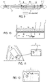
- the figure 7 shows a schematic cross-sectional view of a portion of an iron soleplate according to the invention according to a seventh variant embodiment, and the figure 8 represents a bottom view of the sole illustrated on the figure 7 .
- the support 2 comprises, on its outer face 21 intended to be in contact with the laundry to be ironed, a coating 3 which is substantially identical to that illustrated on the figure 6 : it differs from it only by the absence of rounded fillers in the discontinuous outer enamel layer 33 .
- These coatings are subjected to a 10 mm long scratch, which is induced by a calibrated diamond tip 50 ⁇ m in diameter, which is applied with a gradually increasing force from 0 to 5 Newtons.
- a device marketed under the name “ Microscratch tester ” from the company CSM Instruments is used.
- composition of pigmented B1 enamel slip with magnetizable fillers for aluminum substrate (cookware, aluminum or cast aluminum iron soleplates, etc.).
- a slip of enamel frit B1 is prepared, the composition of which is given below in Table 1 below. ⁇ u>Table 1 ⁇ /u> B1 Slip Components Quantity (parts by weight) F1 enamel frit 100 Water 45 to 60 Boric acid 0 to 4 Molybdic Acid 0 to 4 Potassium Hydroxide 0 to 2 Carbonate; Silicate or metasilicate of soda 0 to 5 Pigments 0 to 30 Ferromagnetic flakes 0.1 to 10
- the contents indicated are parts by weight per 100 parts by weight of frit (reference quantity in the composition of the slip).
- composition of the enamel frit F1 is given in Table 2 below. ⁇ u>Table 2 ⁇ /u> Components of the F1 frit Quantity (mass percentages) SiO 2 33.8 V 2 O 5 6.31 SbO 3.64 Na2O 20.42 BaO 2 3.7 K2O 15.23 TiO 2 15.21 WO 1.69 Total 100
- the contents indicated are mass percentages relative to the weight of the frit.
- a slip of enamel frit B2 is prepared, the composition of which is given below in Table 3 below. ⁇ u>Table 3 ⁇ /u> B2 slip components Quantity (parts by weight) F2 enamel frit 100 Water 35 to 50 Clay 6 to 9 bentonite 0.1 to 0.4 Boric acid 0.2 to 0.4 Quartz 200 8 to 15 ZrO2 0 to 2
- the contents indicated are parts by weight per 100 parts by weight of frit (reference quantity in the composition of the slip).
- composition of the enamel frit F2 is given in Table 4 below. ⁇ u>Table 4 ⁇ /u> Components of the F2 frit Quantity (mass percentages) SiO 2 50-60% Al 2 O 3 5-15% B2O3 _ 8-14% Na2O 6-12% CaO 3-7% ZnO 3-5% CoO 0-4% MnO2 0-4% NiO 0-4% Total 100%
- the contents indicated are mass percentages relative to the weight of the frit.
- a varnish composition V1 is prepared, the composition of which is given below in Table 5 below. ⁇ u>Table 5 ⁇ /u> Varnish Components V1 Quantities (parts by weight) Enamel Frit F 100 Water 40 to 60 Carbomethylcellulose 0 to 10 xanthan gum 0 to 10 Ferromagnetic flakes 0.1 to 10
- a pigmented slurry of B3 enamel frit intended to constitute a white covering enamel is prepared. Its composition is given in Table 6 below. ⁇ u>Table 6 ⁇ /u> B3 Slip Components Quantity (parts by weight) F3 enamel frit 100 Water 30 to 55 Clay 6 to 9 bentonite 0.1 to 0.4 Quartz 3 to 6 organic gum 0 to 0.5 Boric acid 0.2 to 0.4 Mineral pigment for tint shade (ex: yellow ZrSiPr, blue CoO.) 0 to 5 Ferromagnetic flakes 0.1 to 7
- Table 7 shows the composition of the F3 frit used for the white covering enamel. ⁇ u>Table 7 ⁇ /u> Components of the F3 frit Quantity (mass percentages) SiO 2 40-50% Al 2 O 3 0-5% TiO 2 13-20% B2O3 _ 8-14% Na2O 6-12% K20 3-8% CaO 3-7% ZnO 3-5% MgO 0-2% P2O5 _ 0-4% Total 100%
- a first screen-printing paste composition P3 is prepared with fillers, the composition of which is given below in Table 8 below.
- a second filler-free P4 screen-printing paste composition is prepared, the composition of which is also given below in Table 8 below.
- Table 8 Components of P3 and P4 screen-printing pastes Quantity (parts by weight) P3 paste with steel balls Quantity (parts by weight) P4 paste without steel balls Frit F 100 100 black iron oxide 20 20 Oil (terpene) 35 35 steel balls 20 0
- the slip B1 the composition of which is given in Table 1
- the slip B1 is sprayed onto the outer face of the aluminum alloy cookware support, to form an enamel layer 31 (thickness 35 ⁇ m).
- the varnish composition V1 the composition of which is given in Table 5, is applied to this enamel layer 31 to form a varnish layer 32 (thickness 35 ⁇ m).
- the magnetizable flakes contained in the layers of enamel 31 and varnish 32 are oriented by magnetization in certain areas of the protective coating, immediately after the application of these layers, by application of a magnetic field of 70 mT by means of two permanent magnets 51, 52 arranged under the substrate (in this case under the face of the support opposite to that which is coated), as is schematically illustrated in the figures 9 and 10 .
- the mica flakes thanks to their coating of magnetic iron oxide, are oriented along the field lines, i.e. in line with the magnet, and in particular substantially vertically in areas P1 and P2 shown on the figure 9 .
- the viscosity of the layers applied be as low as possible.
- a non-VOC heavy solvent such as hexylene glycol makes it possible to reduce evaporation on spraying and provides a longer application time for the magnets, allowing orientation after spraying. facilitated. Any drying of the enamel layer before to have oriented the magnetic charges. However, the magnets can be applied until the final drying of the coating, to consolidate the orientation. This mode is particularly recommended if you want to obtain a decor with a clear perception of relief.
- Example 1 The same coating as in Example 1 is applied to the cap of the iron soleplate, except for the absence of steel balls in the outer layer of enamel (this outer layer of enamel being obtained from P4 silkscreen paste without steel balls).
- the orientation of the magnetizable particles is carried out, as for example 1, by applying a magnetic field of 70 mT by means of two permanent magnets 51, 52 arranged under the substrate (in this case under the face of the support opposite to that which is clothed), as shown schematically on the figures 9 and 10 and really on the figure 11 .
- the mica flakes thanks to their coating of magnetic iron oxide, are oriented along the field lines, i.e. in line with the magnet substantially vertically (zone C) .
- This item will generally be treated in 2 coats with 2 firings.
- a first coat of enamel slip B2 (see Tables 3 and 4) which is generally opaque, is applied by spraying to the interior and exterior wall of a cast iron cookware support previously shot-blasted and degreased. This layer will be baked between 800°C and 850°C for 4 to 12 minutes.
- the coating enamel slip B3 is applied.
- this second layer will be 100 to 200 ⁇ m. This layer will make it possible to obtain the mechanical reinforcement linked to the orientation of the flakes during the application of the magnetic field. This step will be favored and facilitated when the enamel slip is still liquid (promoted mobility). This second firing will take place between 750°C and 820°C for 4 to 12 minutes.
- enamels described above in the case of cast steel metals for culinary applications or small household appliances can be applied either inside the article or outside the article. Their reinforcement of the mechanical properties can take place inside the article (multiple contact with utensils: whisk, knife, spatula%) or outside the article (cooking plate, sink, grid of oven).
- the coating described above shows a significant improvement over the same coating lacking oriented magnetizable flakes in slip B3.
- the optimization of the resistance to chipping is beneficial for example by the impact of a metal utensil during conventional use.
- COMPARATIVE EXAMPLE 4 Production of a protective coating on the outer face of an iron soleplate free of magnetizable particles.
- a protective coating comprising a layer of enamel 31, on which is deposited a layer of varnish 32, then a layer of serigraphic enamel 33.
- the protective coating of comparative example 4 differs from that of example 1 by the absence of magnetizable flakes in the layers of enamel 31, varnish 32, and screen-printed enamel layer 33.
- Example 1 (with oriented spangles) Measurement carried out at the level of a zone C 70-80 ⁇ m 27.22 ⁇ 1.41
- Example 1 (with non-oriented flakes) Measurement carried out at the level of a zone B 70-80 ⁇ m 21.39 ⁇ 0.76
- Example 2 (with oriented flakes) Measurement carried out at the level of zone C on the figures 11 and 12 70-80 ⁇ m 26.79 ⁇ 1.33
- Example 2 (with non-oriented flakes) Measurement carried out at the level of zone B on the figures 11 and 12 70-80 ⁇ m 21.76 ⁇ 0.82 Comparative Example 4 (without flakes) 70-80 ⁇ m 23.04 ⁇ 0.44
- the delamination values indicated in table 9 correspond to an average metal chipping value for 4 measurements per sample.
Description
La présente invention concerne de manière générale un article muni d'un revêtement émaillé incorporant des particules anisotropes (de type paillettes ou fibres) et pouvant être utilisé sur tout type de substrat, notamment métallique.The present invention generally relates to an article provided with an enamel coating incorporating anisotropic particles (of flake or fiber type) and which can be used on any type of substrate, in particular metal.
La présente invention concerne également un procédé d'application d'un tel revêtement sur un support.The present invention also relates to a method for applying such a coating to a support.
Le domaine visé est en premier lieu celui des articles chauffants.The field targeted is primarily that of heating articles.
Par article chauffant, on entend, au sens de la présente invention, un article qui possède son propre système de chauffage, ou un article qui est chauffé par un système extérieur et qui est apte à transmettre l'énergie calorifique apportée par ce système à un matériau ou objet tiers au contact dudit article, ou encore un article qui est destiné à recevoir un autre article préalablement chauffé.By heating article is meant, within the meaning of the present invention, an article which has its own heating system, or an article which is heated by an external system and which is able to transmit the calorific energy provided by this system to a third-party material or object in contact with said article, or else an article which is intended to receive another previously heated article.
A titre d'exemples d'articles chauffants utilisables selon la présente invention, on peut notamment citer les articles culinaires (tels que des poêles sauteuses, casseroles, woks, crépières, fait-tout, marmites, cocottes...), ou les couvercles chauffants et les bols mixeurs chauffants d'appareils de préparation de nourriture ou de boisson. Mais la présente invention peut également concerner tout autre type de surface et d'articles, tels que des articles de table comme des dessous de plat, des semelles d'un fer à repasser, des fers à friser, et des fers à lisser, des radiateurs, des porte-serviettes ou des poêles à bois, ou des plaques de barbecue, des coffres de barbecue ou des cuves de barbecue, des capots de chauffe plat.By way of examples of heating articles that can be used according to the present invention, mention may in particular be made of culinary articles (such as sauté pans, saucepans, woks, crepe pans, stewpans, pots, casserole dishes, etc.), or lids heated bowls and mixing bowls of food or drink preparation appliances. But the present invention can also relate to any other type of surface and articles, such as table articles such as trivets, soleplates of an iron, curling irons, and straightening irons, radiators, towel rails or wood-burning stoves, or barbecue plates, barbecue chests or barbecue tubs, flat heater hoods.
Les revêtements émaillés sont particulièrement appréciés dans le domaine des articles chauffants, notamment culinaires, et dans celui des fers à repasser, et plus précisément des semelles de fers à repasser.Enamel coatings are particularly appreciated in the field of heating articles, in particular culinary articles, and in that of irons, and more specifically iron soleplates.
Dans le cas des semelles de fers à repasser, les propriétés tribologiques, thermiques et physicochimiques du revêtement sont primordiales pour assurer la facilité de repassage. Un revêtement en émail est donc un compromis idéal pour revêtir la coiffe métallique d'une semelle de fer à repasser car il possède une bonne tenue thermique, un faible coefficient de frottement évoluant peu avec la température, un comportement hydrophile et une tenue à l'hydrolyse. L'inconvénient des revêtements émaillés pour les applications de type fer à repasser (comprenant notamment les fers à vapeur, les fers sec et les centrales vapeurs) réside dans leur faible tenue aux chocs. En effet, il pourra apparaître au niveau du bord revêtu de la coiffe émaillée (et plus particulièrement sur le pourtour de la coiffe revêtue), des petits éclats d'émail, notamment si le revêtement est soumis à des chocs causés par la manutention. De petits éclats d'émail pourront également apparaître par contacts répétés sur des pièces métalliques fixées sur les textiles à repasser (boutonnières, boutons pression, fermetures à glissière...).In the case of iron soleplates, the tribological, thermal and physicochemical properties of the coating are essential to ensure ease of ironing. An enamel coating is therefore an ideal compromise for coating the metal cap of an iron soleplate because it has good thermal resistance, a low friction coefficient that changes little with temperature, hydrophilic behavior and resistance to hydrolysis. The disadvantage of enamel coatings for applications of the iron type (including in particular steam irons, dry irons and steam generators) lies in their low resistance to shocks. Indeed, it may appear at the level of the coated edge of the enamelled cap (and more particularly on the periphery of the coated cap), small chips of enamel, in particular if the coating is subject to shocks caused by handling. Small chips of enamel may also appear through repeated contact on metal parts attached to textiles to be ironed (buttonholes, press studs, zippers, etc.).
Les revêtements en émail sont également particulièrement appréciés dans le domaine des articles culinaires car ils permettent d'obtenir des revêtements colorés qui présentent non seulement une bonne tenue au lave-vaisselle, une résistance élevée à la flamme et à la rayure, mais aussi un aspect décoratif primordial, bien souvent déterminant dans le choix du consommateur. Ils présentent toutefois l'inconvénient de s'écailler facilement au niveau de certaines zones particulièrement sensibles, qui sont les zones de forte sollicitation de l'article culinaire. Ces zones sont en général situées dans les zones de courbure de l'article ou dans les zones de raccordement avec la ou les poignées.Enamel coatings are also particularly appreciated in the field of cookware because they make it possible to obtain colored coatings which not only have good dishwasher resistance, high flame and scratch resistance, but also a primordial decorative element, very often decisive in the consumer's choice. However, they have the drawback of flaking off easily at certain particularly sensitive zones, which are the zones of high stress on the cooking utensil. These zones are generally located in the zones of curvature of the article or in the zones of connection with the handle or handles.
A titre de zone sensible, on peut notamment citer, pour un article culinaire, la zone de jonction entre le fond de la calotte et la paroi latérale de l'article ou le bord supérieur de l'article qui est rogné (rectifié) pour donner un bord lisse et plan, ou encore la zone supportant l'accroche de la poignée (car elle peut subir une déformation consécutive au soudage de l'élément de fixation), le fond qui en contact avec les grilles des bruleurs.By way of sensitive zone, mention may in particular be made, for a culinary article, of the junction zone between the bottom of the cap and the side wall of the article or the upper edge of the article which is trimmed (rectified) to give a smooth, flat edge, or even the area supporting the grip of the handle (because it can undergo deformation following the welding of the fixing element), the bottom which is in contact with the grills of the burners.
En outre, les revêtements émaillés présentent également l'inconvénient de présenter une dilatation thermique différente en fonction de la position de la flamme au niveau du fond de l'article. Or, il est important que le revêtement présente une dilatation thermique homogène, sinon on génère des microfissures qui nuisent à la tenue au lave-vaisselle.In addition, enamel coatings also have the disadvantage of having a different thermal expansion depending on the position of the flame at the bottom of the article. However, it is important that the coating has a homogeneous thermal expansion, otherwise microcracks are generated which are detrimental to resistance to the dishwasher.
Pour éviter les problèmes susmentionnés, la demanderesse a mis au point un revêtement émaillé comportant des paillettes, et plus généralement des particules de forme anisotrope, qui sont orientées de manière essentiellement perpendiculaire au revêtement formé dans les zones sensibles.To avoid the aforementioned problems, the applicant has developed an enamel coating comprising flakes, and more generally particles of anisotropic shape, which are oriented essentially perpendicular to the coating formed in the sensitive areas.
Par particules essentiellement perpendiculaires au revêtement, on entend, au sens de la présente invention, des particules qui sont majoritairement inclinées d'un angle α compris entre 20° et 90°, de préférence entre 45 et 90°, et mieux entre 60 et 90° par rapport au plan moyen du revêtement.By particles essentially perpendicular to the coating is meant, within the meaning of the present invention, particles which are mainly inclined at an angle α between 20° and 90°, preferably between 45 and 90°, and better still between 60 and 90 ° in relation to the average plane of the coating.
Il est connu de l'homme de l'art d'intégrer des particules telles que des paillettes dans des revêtements de type émail. Ainsi, par exemple, les brevets français
Par ailleurs, la demande internationale
Toutefois, aucune de ces références ne décrit une quelconque orientation de ces particules (paillettes, pigments ou charges) dans une zone spécifique du revêtement, notamment en vue de son renforcement, ni a fortiori que cette orientation puisse être réalisée par application d'un champ magnétique au niveau de cette zone.However, none of these references describes any orientation of these particles (flakes, pigments or fillers) in a specific zone of the coating, in particular with a view to its reinforcement, nor a fortiori that this orientation can be achieved by applying a field magnetic in this area.
Plus particulièrement, la présente invention a pour objet un article chauffant comprenant un support présentant deux faces opposées, dont l'une au moins est recouverte d'un revêtement de protection, caractérisé en ce que ledit revêtement de protection comprend au moins une couche d'émail dans laquelle sont dispersées des particules de forme anisotrope, la couche d'émail comprenant au moins une zone dans laquelle les particules anisotropes sont essentiellement perpendiculaires à la couche d'émail sous forme de film.More particularly, the subject of the present invention is a heating article comprising a support having two opposite faces, at least one of which is covered with a protective coating, characterized in that said protective coating comprises at least one layer of enamel in which particles of anisotropic shape are dispersed, the enamel layer comprising at least one zone in which the anisotropic particles are essentially perpendicular to the enamel layer in the form of a film.
Les particules de forme anisotrope peuvent avantageusement représenter 0,05 à 10 %, de préférence 0,1 à 7 %, et mieux 1 à 5 % en poids du poids total de la couche d'émail. Idéalement, les particules de forme anisotrope représentent 2 à 3 % en poids du poids total de la couche d'émail.The particles of anisotropic shape can advantageously represent 0.05 to 10%, preferably 0.1 to 7%, and better still 1 to 5% by weight of the total weight of the enamel layer. Ideally, the particles of anisotropic shape represent 2 to 3% by weight of the total weight of the enamel layer.
Dans la zone où les particules sont essentiellement perpendiculaires, la résistance à l'écaillage et aux chocs est nettement améliorée. En outre, cette zone ne présente pas une dilatation thermique différente de celle du reste du revêtement.In the area where the particles are essentially perpendicular, resistance to chipping and impact is significantly improved. In addition, this area does not exhibit a different thermal expansion from that of the rest of the coating.
Par particules de forme anisotrope, on entend au sens de la présente invention des particules dont les dimensions caractéristiques ne sont pas identiques dans toutes les directions, comme par exemples des fibres (de forme essentiellement unidimensionnelle) ou des paillettes (de forme essentiellement bidimensionnelle ou plate)By particles of anisotropic shape, is meant within the meaning of the present invention particles whose characteristic dimensions are not identical in all directions, such as for example fibers (of essentially one-dimensional shape) or flakes (of essentially two-dimensional or flat shape )
Par particules essentiellement perpendiculaires au film, on entend au sens de la présente invention, des particules qui sont majoritairement inclinées d'un angle α compris entre 20° et 90° par rapport au plan moyen du film.By particles essentially perpendicular to the film, is meant within the meaning of the present invention, particles which are mainly inclined at an angle α of between 20° and 90° relative to the mean plane of the film.
Une telle orientation des particules anisotropes peut être obtenue de différentes manières, en fonction du type des particules anisotropes utilisées.Such an orientation of the anisotropic particles can be obtained in different ways, depending on the type of anisotropic particles used.
Ainsi, dans le cas de particules aptes à être orientées par un moyen mécanique (comme les fibres), l'orientation essentiellement perpendiculaire à la couche de revêtement peut par exemple résulter d'un positionnement lié au procédé d'application du revêtement, comme par exemple l'orientation au travers d'un applicateur monodirectionnel comme une micro-buse.Thus, in the case of particles capable of being oriented by a mechanical means (such as fibers), the orientation essentially perpendicular to the coating layer can for example result from a positioning linked to the method of application of the coating, as by example orientation through a one-way applicator such as a micro-nozzle.
Dans le cas de particules aptes à être orientées par un moyen physique (par exemple électrique ou magnétique), l'orientation essentiellement perpendiculaire des particules anisotropes par rapport à la couche de revêtement peut résulter d'un positionnement consécutif ou simultané à l'application du revêtement, comme par exemple l'orientation de particules magnétisables sous l'effet d'un champ magnétique ou de particules électrisables sous l'effet d'un champ électrique.In the case of particles able to be oriented by a physical means (for example electrical or magnetic), the essentially perpendicular orientation of the anisotropic particles with respect to the coating layer can result from a consecutive or simultaneous positioning with the application of the coating, such as for example the orientation of magnetizable particles under the effect of a magnetic field or electrisable particles under the effect of an electric field.
Par particules magnétisables, on entend, au sens de la présente invention des particules aptes à être orientées sous l'effet d'un champ magnétique.By magnetizable particles is meant, within the meaning of the present invention, particles capable of being oriented under the effect of a magnetic field.
Les particules magnétisables peuvent se présenter sous différentes natures.The magnetizable particles can come in different natures.
Dans le cadre de la présente invention, les particules magnétisables peuvent être avantageusement des particules comprenant au moins un métal ferromagnétique.In the context of the present invention, the magnetizable particles can advantageously be particles comprising at least one ferromagnetic metal.
Elles peuvent être de nature homogène, c'est-à-dire constituées du même matériau, ou de nature composite, c'est-à-dire que les particules magnétisables ont une structure cœur-enveloppe, dans laquelle le métal ferromagnétique est dans le cœur et/ou dans l'enveloppe desdites particules.They can be of a homogeneous nature, that is to say made up of the same material, or of a composite nature, that is to say that the magnetizable particles have a core-envelope structure, in which the ferromagnetic metal is in the core and/or in the envelope of said particles.
A titre d'exemples de particules magnétisables composites, on peut notamment citer les paillettes de mica enrobées d'un matériau ferromagnétique, comme par exemple les paillettes de mica enrobées d'une ferrite de la forme (MO, Fe2O3) où M est un métal divalent, par exemple des paillettes de mica enrobées de Fe3O4 (magnétite) ou de Fe2O3, ou de FeO. D'autres matériaux présentant des propriétés ferromagnétiques peuvent également être utilisés : on peut par exemple citer le cobalt, le nickel, ou l'alliage d'Heussler constitué uniquement de métaux non ferromagnétiques (61 % Cu, 24 % Mn, 15 % Al), ou certaines terres rares comme les lanthanides, les oxydes de cuivre-manganèse et aluminium.As examples of composite magnetizable particles, mention may in particular be made of mica flakes coated with a ferromagnetic material, such as for example mica flakes coated with a ferrite of the form (MO, Fe2O3) where M is a metal divalent, for example mica flakes coated with Fe 3 O 4 (magnetite) or Fe 2 O 3 , or FeO. Other materials with ferromagnetic properties can also be used: for example, mention may be made of cobalt, nickel, or the Heussler alloy consisting solely of non-ferromagnetic metals (61% Cu, 24% Mn, 15% Al) , or certain rare earths such as lanthanides, copper-manganese and aluminum oxides.
L'avantage présenté par les paillettes de mica enrobées réside dans le fait qu'elles résistent particulièrement bien à la température de cuisson élevée des émaux pour métaux, à savoir des températures allant de 550°C pour des émaux sur aluminium à 850°C pour des émaux sur acier ou fonte d'acier. De plus, ces paillettes en mica offrent une meilleure résistance à l'alcalinité des barbotines d'émail obtenues par hydrolyse (par exemple une barbotine d'émail pour aluminium présente un pH de 13). On peut également citer les fibres d'acier inoxydable enrobées d'un matériau sol-gel, comme protection vis-à-vis de la corrosion lors des étapes de mise en œuvre du revêtement, ou des paillettes dont le cœur est en métal ferromagnétique et l'enveloppe est en un matériau sol-gel.The advantage of coated mica flakes lies in the fact that they are particularly resistant to the high firing temperature of enamels for metals, namely temperatures ranging from 550°C for enamels on aluminum to 850°C for enamels on steel or cast iron. In addition, these mica flakes offer better resistance to the alkalinity of the enamel slips obtained by hydrolysis (for example an enamel slip for aluminum has a pH of 13). Mention may also be made of stainless steel fibers coated with a sol-gel material, as protection against corrosion during the stages of implementation of the coating, or flakes whose core is made of ferromagnetic metal and the envelope is made of a sol-gel material.
Le revêtement selon l'invention peut en outre avantageusement comprendre des particules non magnétisables pour améliorer le renforcement du revêtement.The coating according to the invention can also advantageously comprise non-magnetizable particles to improve the reinforcement of the coating.
Par particules non magnétisables, on entend, au sens de la présente invention des particules non magnétisables ou faiblement magnétisables ayant un moment magnétique nul ou faible (inférieur à 1 uem/g).By non-magnetizable particles is meant, within the meaning of the present invention, non-magnetizable or weakly magnetizable particles having a zero or weak magnetic moment (less than 1 emu/g).
Ces particules non magnétisables peuvent être de forme quelconque (sphériques, fibres ou paillettes ou « irrégulières»), de taille micrométrique, voire même nanométrique.These non-magnetizable particles can be of any shape (spherical, fibers or flakes or “irregular”), of micrometric or even nanometric size.
A titre de particules non magnétisables utilisables dans le cadre de la présente invention, on peut notamment citer les paillettes de mica, et les paillettes de mica ou de silice enrobées de dioxyde de titane.As non-magnetizable particles that can be used in the context of the present invention, mention may in particular be made of mica flakes, and mica or silica flakes coated with titanium dioxide.
Le revêtement de protection de la présente invention peut en outre avantageusement comporter, adjacente à la zone dans laquelle les particules sont essentiellement perpendiculaires à la couche de revêtement en émail, au moins une zone dans laquelle les particules sont disposées de manière essentiellement parallèle et/ou aléatoire à la couche d'émail se présentant sous forme de film, de manière à renforcer les zones sensibles.The protective coating of the present invention may further advantageously comprise, adjacent to the zone in which the particles are essentially perpendicular to the enamel coating layer, at least one zone in which the particles are arranged in an essentially parallel and/or random to the layer of enamel in the form of a film, so as to reinforce the sensitive areas.
Par particules essentiellement parallèles à la couche de revêtement émaillé, on entend au sens de la présente invention, des particules qui sont majoritairement inclinées d'un angle α compris entre 0° et 20° par rapport à la couche de revêtement.By particles essentially parallel to the enamel coating layer, is meant within the meaning of the present invention, particles which are predominantly inclined at an angle α of between 0° and 20° with respect to the coating layer.
L'alternance des zones dans lesquelles les particules sont disposées de manière essentiellement parallèle et/ou aléatoire à la couche d'émail et des zones dans lesquelles les particules sont essentiellement perpendiculaires à la couche d'émail permet de définir un décor, qui pourra être perçu par l'utilisateur comme un décor tridimensionnel.The alternation of the zones in which the particles are arranged in an essentially parallel and/or random manner to the enamel layer and the zones in which the particles are essentially perpendicular to the enamel layer makes it possible to define a decoration, which may be perceived by the user as a three-dimensional decor.
Selon un premier mode de réalisation particulièrement avantageux de la présente invention, la couche d'émail du revêtement de protection selon l'invention peut comprendre une seule couche continue et destinée à être disposée sur un support.According to a first particularly advantageous embodiment of the present invention, the enamel layer of the protective coating according to the invention may comprise a single continuous layer intended to be placed on a support.
Selon un deuxième mode de réalisation particulièrement avantageux de la présente invention, la couche d'émail du revêtement de protection selon l'invention peut comprendre :
- une sous-couche transparente et exempte de particules magnétisables, qui est continue et est destinée à être disposée sur un support, et
- une couche de finition dans laquelle sont dispersées les particules magnétisables, la couche de finition étant continue et recouvrant partiellement ou complètement la sous-couche.
- a transparent underlayer free of magnetizable particles, which is continuous and is intended to be placed on a support, and
- a top coat in which the magnetizable particles are dispersed, the top coat being continuous and partially or completely covering the undercoat.
Par couche de finition, on entend, au sens de la présente invention une couche qui est destinée à être en contact avec l'environnement.By finishing layer is meant, within the meaning of the present invention, a layer which is intended to be in contact with the environment.
Selon un troisième mode de réalisation particulièrement avantageux de la présente invention, la couche d'émail du revêtement de protection selon l'invention peut comprendre :
- une sous-couche colorée et exempte de particules magnétisables, qui est continue et est destinée à être disposée sur un support, et
- une couche de finition dans laquelle sont dispersées les particules magnétisables, la couche de finition étant continue et recouvrant partiellement ou complètement la sous-couche.
- a colored underlayer free of magnetizable particles, which is continuous and is intended to be placed on a support, and
- a top coat in which the magnetizable particles are dispersed, the top coat being continuous and partially or completely covering the undercoat.
Selon un quatrième mode de réalisation particulièrement avantageux de la présente invention, la couche d'émail du revêtement de protection selon l'invention peut comprendre :
- une sous-couche transparente ou colorée et exempte de particules magnétisables, la sous-couche étant continue et destinée à être disposée sur un support,
- une première couche de finition dans laquelle sont dispersées des particules magnétisables, la première couche de finition étant continue et recouvrant complètement la sous-couche, et
- une deuxième couche de finition dans laquelle sont également dispersées des particules magnétisables, la deuxième couche de finition étant continue et recouvrant partiellement ou complètement la première couche de finition.
- a transparent or colored underlayer free of magnetizable particles, the underlayer being continuous and intended to be placed on a support,
- a first topcoat in which magnetizable particles are dispersed, the first topcoat being continuous and completely covering the undercoat, and
- a second topcoat in which magnetizable particles are also dispersed, the second topcoat being continuous and partially or completely covering the first topcoat.
Selon un cinquième mode de réalisation particulièrement avantageux de la présente invention, la couche d'émail du revêtement de protection selon l'invention peut comprendre :
- une sous-couche colorée, dans laquelle sont dispersées des particules magnétisables, la sous-couche colorée étant continue et destinée à être disposée sur un support, et
- une couche de finition transparente, dans laquelle sont également dispersées des particules magnétisables, la couche de finition étant continue et recouvrant partiellement ou complètement la sous-couche colorée.
- a colored underlayer, in which magnetizable particles are dispersed, the colored underlayer being continuous and intended to be placed on a support, and
- a transparent top coat, in which magnetizable particles are also dispersed, the top coat being continuous and partially or completely covering the colored undercoat.
Un tel mode de réalisation présente l'avantage de renforcer mécaniquement chaque couche et la liaison mécanique entre chaque couche.Such an embodiment has the advantage of mechanically reinforcing each layer and the mechanical connection between each layer.
De manière avantageuse, pour les modes de réalisation à au moins deux couches (deuxième à cinquième modes de réalisation), la sous-couche peut présenter une épaisseur comprise entre 5 et 30 µm, et la ou les couches de finition peuvent présenter une épaisseur comprise entre 20 et 60 µm.Advantageously, for the embodiments with at least two layers (second to fifth embodiments), the underlayer can have a thickness of between 5 and 30 μm, and the topcoat or layers may have a thickness of between 20 and 60 μm.
Selon un sixième mode de réalisation particulièrement avantageux de la présente invention, le revêtement de protection selon l'invention peut comprendre :
- une couche d'émail comprenant :
- ▪ une sous-couche exempte de particules magnétisables et qui est transparente ou colorée, cette sous-couche étant continue et destinée à être disposée sur un support, et
- ▪ au moins une couche médiane qui est soit une couche colorée, soit une couche magnétisable laquelle dans laquelle sont dispersées des particules magnétisables, ladite couche médiane étant continue et recouvrant partiellement ou complètement ladite sous-couche, et
- une première couche de vernis magnétisable, continue et dans laquelle sont dispersées des particules magnétisables, cette première couche de vernis recouvrant partiellement ou complètement la couche médiane en émail, et
- une deuxième couche de vernis incolore et transparente, non magnétisable, continue et recouvrant complètement la première couche de vernis magnétisable, de manière à garantir la tenue chimique et la tenue au lave-vaisselle.
- an enamel layer comprising:
- ▪ a sub-layer free of magnetizable particles and which is transparent or colored, this sub-layer being continuous and intended to be placed on a support, and
- ▪ at least one middle layer which is either a colored layer or a magnetizable layer in which magnetizable particles are dispersed, said middle layer being continuous and partially or completely covering said sub-layer, and
- a first layer of magnetizable varnish, continuous and in which magnetizable particles are dispersed, this first layer of varnish partially or completely covering the middle enamel layer, and
- a second layer of colorless and transparent varnish, non-magnetizable, continuous and completely covering the first layer of magnetizable varnish, so as to guarantee chemical resistance and resistance to the dishwasher.
De manière avantageuse, pour ce sixième mode de réalisation, la sous-couche peut présenter une épaisseur comprise entre 5 et 30 µm, la couche médiane en émail peut présenter une épaisseur comprise entre 20 et 60 µm. En ce qui concerne les couches de vernis recouvrant la couche médiane en émail, la couche de vernis magnétisable peut présenter avantageusement une épaisseur comprise entre 15 et 40 µm, et la couche de vernis de protection peut présenter une épaisseur comprise entre 10 et 20 µm.Advantageously, for this sixth embodiment, the underlayer can have a thickness of between 5 and 30 μm, the middle enamel layer can have a thickness of between 20 and 60 μm. As regards the layers of varnish covering the middle layer of enamel, the layer of magnetizable varnish can advantageously have a thickness of between 15 and 40 μm, and the layer of protective varnish can have a thickness of between 10 and 20 μm.
Pour l'ensemble de ces modes de réalisation, par couche colorée (qu'il s'agisse d'une sous-couche, d'une couche de finition ou d'une couche de vernis), on entend au sens de la présente invention une couche comportant au moins un pigment opaque choisi parmi les pigments thermostables comme par exemple les spinelles, les pigments céramiques, les oxydes, les organométalliques comme le bleu d'outremer, les pigments en paillettes micacé ou silicié (non magnétisables), les sels métalliques, les pigments semi-conducteurs thermochromes et leurs mélanges.For all of these embodiments, by colored layer (whether it is an undercoat, a finishing coat or a varnish coat), it is meant within the meaning of the present invention a layer comprising at least one opaque pigment chosen from thermostable pigments such as for example spinels, ceramic pigments, oxides, organometallics such as ultramarine blue, pigments in micaceous or silicon flakes (non-magnetizable), metal salts , thermochromic semiconductor pigments and mixtures thereof.
De manière avantageuse, quelque soit le mode de réalisation envisagé, la couche d'émail du revêtement de protection de l'article chauffant selon l'invention peut en outre comporter une couche d'émail externe discontinue, qui est sérigraphiée ou tampographiée.Advantageously, whatever the embodiment envisaged, the enamel layer of the protective coating of the heating article according to the invention may also comprise a discontinuous outer enamel layer, which is screen-printed or pad-printed.
Dans le cas où l'article chauffant selon l'invention est un article culinaire, la couche externe en émail peut également comprendre des charges arrondies, qui sont avantageusement sphériques avec un diamètre compris entre 5 et 40 µm, et de préférence entre 15 et 20 µm, l'épaisseur de la couche externe variant entre 10 et 30 µm. Ces billes font saillie à la surface de la couche externe d'émail.In the case where the heating article according to the invention is a culinary article, the external enamel layer can also comprise rounded fillers, which are advantageously spherical with a diameter of between 5 and 40 μm, and preferably between 15 and 20 µm, the thickness of the outer layer varying between 10 and 30 µm. These beads protrude from the surface of the outer enamel layer.
A titre de charges arrondies (ou billes) utilisables dans la couche d'émail externe selon l'invention, on peut notamment citer les billes en acier inoxydable, en cuivre, en bronze ou en acier réfractaire.As rounded fillers (or balls) that can be used in the outer enamel layer according to the invention, mention may in particular be made of balls made of stainless steel, copper, bronze or refractory steel.
De préférence, on utilise des billes en acier inoxydable. Les charges arrondies sont avantageusement présentes dans la couche externe d'émail à raison de 1 à 5 % en poids par rapport au poids total de la couche externe. Ces charges arrondies permettent à la fois d'augmenter la résistance à l'usure du revêtement d'émail et d'en réduire (lorsque les charges affleurent à la surface de la couche d'émail) le coefficient de frottement en raison de la diminution de la surface de contact entre l'article et la plaque de cuisson et de la moindre dureté des billes par rapport à celle de la couche d'émail. Ainsi, le revêtement est facilement nettoyable et ne présente pas de risque de rayer des surfaces sensibles telles que des plaques vitrocéramiques ou à induction.Preferably, stainless steel balls are used. The rounded fillers are advantageously present in the outer layer of enamel at a rate of 1 to 5% by weight relative to the total weight of the outer layer. These rounded fillers make it possible both to increase the wear resistance of the enamel coating and to reduce (when the fillers are flush with the surface of the enamel layer) the coefficient of friction due to the decrease the contact surface between the article and the cooking plate and the lesser hardness of the balls compared to that of the enamel layer. Thus, the coating is easily cleanable and presents no risk of scratching sensitive surfaces such as ceramic or induction hobs.
En ce qui concerne la nature du support de l'article, celui-ci peut être réalisé en un matériau choisi parmi les métaux, le verre et les céramiques.As regards the nature of the support of the article, the latter can be made of a material chosen from among metals, glass and ceramics.
A titre de supports métalliques conformes à l'invention, on peut citer les supports présentant une structure :
- monocouche en aluminium ou alliage d'aluminium poli, brossé ou microbillé, sablé, traité chimiquement, ou en fonte d'aluminium, ou en acier inoxydable poli, brossé ou microbillé, ou en fonte d'acier ou d'aluminium,
- soit un support métallique multicouches, en partie ou en totalité, comprenant de l'extérieur vers l'intérieur les couches suivantes acier inoxydable ferritique / aluminium/acier inoxydable austénitique ou encore acier inoxydable / aluminium / cuivre / aluminium / acier inoxydable austénitique, ou encore une calotte d'aluminium de fonderie, d'aluminium ou d'alliages d'aluminium doublée d'un fond extérieur en acier inoxydable.
- monolayer in polished, brushed or microblasted aluminum or aluminum alloy, sandblasted, chemically treated, or in cast aluminum, or in polished, brushed or microblasted stainless steel, or in cast steel or aluminium,
- either a multi-layer metal support, in part or in whole, comprising from the outside towards the inside the following layers ferritic stainless steel/aluminum/austenitic stainless steel or even stainless steel/aluminum/copper/aluminum/austenitic stainless steel, or else a cap of cast aluminium, aluminum or aluminum alloys lined with a stainless steel outer bottom.
A titre d'exemples d'articles selon l'invention, on peut notamment citer les articles culinaires, les couvercles chauffants ou les bols mixeurs chauffants d'appareils de préparation de nourriture ou de boisson, ou encore les semelles de fer à repasser, les articles de tables comme par exemple les dessous de plats, des radiateurs ou des poêles à bois, ou encore des fers à friser, et des fers à lisser, des porte-serviettes ou des plaques de barbecue, des coffres de barbecue ou des cuves de barbecue.By way of examples of articles according to the invention, mention may in particular be made of cookware, heated lids or heated mixer bowls of food or drink preparation appliances, or even the soles of iron, table items such as trivets, radiators or wood-burning stoves, or even curling irons and straightening irons, towel racks or barbecue plates, barbecue or barbecue tubs.
Enfin, la présente invention a encore pour objet un procédé de fabrication, sur un support d'article chauffant, d'un revêtement comprenant au moins une couche d'émail dans laquelle sont dispersées des particules de forme anisotrope,
caractérisé en ce qu'il comprend une étape d'orientation desdites particules anisotropes par un moyen physique (par exemple par application d'un champ électrique ou magnétique) ou mécanique (par exemple lors de l'application du revêtement à l'aide d'applicateur monodirectionnel comme une micro-buse) dans au moins une zone de la couche d'émail.Finally, another subject of the present invention is a process for the manufacture, on a support of a heating article, of a coating comprising at least one layer of enamel in which particles of anisotropic shape are dispersed,
characterized in that it comprises a step of orienting said anisotropic particles by a physical means (for example by application of an electric or magnetic field) or mechanical means (for example during the application of the coating using one-way applicator such as a micro-nozzle) in at least one area of the enamel layer.
Le support et les particules anisotropes sont tels que définis précédemment.The support and the anisotropic particles are as defined above.
De manière avantageuse, le procédé selon l'invention, peut comprendre les étapes suivantes :
- a) la fourniture du support ;
- b) l'application par pulvérisation sur l'une des faces du support d'au moins une composition d'émail dans laquelle sont dispersées des particules anisotropes comprenant des particules magnétisables ;
- c) l'orientation par aimantation des particules magnétisables en appliquant un champ magnétique, l'aimantation c) étant réalisée soit au cours de l'application b) de la composition d'émail sur le support, soit immédiatement après ladite étape d'application b) ; puis
- d) de manière optionnelle une étape de séchage, de préférence à une température comprise entre la température ambiante et 150°C, suivie
- e) d'une cuisson réalisée à une température d'au moins 500°C.
- a) the provision of the medium;
- b) the application by spraying on one of the faces of the support of at least one enamel composition in which are dispersed anisotropic particles comprising magnetizable particles;
- c) the orientation by magnetization of the magnetizable particles by applying a magnetic field, the magnetization c) being carried out either during the application b) of the enamel composition on the support, or immediately after the said application step b); then
- d) optionally a drying step, preferably at a temperature between room temperature and 150°C, followed
- e) firing carried out at a temperature of at least 500°C.
Les particules magnétisables sont telles que définies précédemment.The magnetizable particles are as defined above.
Dans ce mode de réalisation du procédé selon l'invention, on utilise des particules de forme anisotrope magnétisables : l'étape d) d'orientation des particules magnétisables est donc une étape d'aimantation réalisée par application d'un champ magnétique, qui est réalisée soit au cours de l'application de la composition d'émail, soit postérieurement à cette étape d'application d), mais en tout état de cause préalablement à l'étape e) de cuisson.In this embodiment of the method according to the invention, magnetizable particles of anisotropic shape are used: step d) of orientation of the magnetizable particles is therefore a magnetization step carried out by application of a magnetic field, which is carried out either during the application of the enamel composition, or after this application step d), but in any event prior to the baking step e).
On obtient après séchage et cuisson un revêtement de protection présentant simultanément une résistance élevée à l'écaillage et aux chocs et une dilatation thermique homogène dans tout le revêtement.After drying and curing, a protective coating is obtained which simultaneously exhibits high resistance to chipping and impact and homogeneous thermal expansion throughout the coating.
Dans ce mode de réalisation du procédé selon l'invention dans lequel les particules anisotropes sont magnétisables et orientées par aimantation, l'étape b) d'application de la couche d'émail peut avantageusement comprendre les sous-étapes suivantes :
- b1) la pulvérisation sur l'une des faces du support d'une composition d'émail de sous-couche exempte de particules magnétisables, ladite composition d'émail étant transparente ou colorée pour former une sous-couche non cuite ; puis
- b2) la pulvérisation sur cette sous-couche non cuite d'au moins une composition d'émail de finition dans laquelle sont dispersées des particules magnétisables, pour former une couche d'émail de finition non cuite.
- b1) the spraying on one of the faces of the support of an undercoat enamel composition free of magnetizable particles, said enamel composition being transparent or colored to form an unfired undercoat; then
- b2) the spraying on this unbaked underlayer of at least one finishing enamel composition in which magnetizable particles are dispersed, to form an unbaked finishing enamel layer.
De préférence, l'étape b) d'application de la couche d'émail peut en outre comprendre après l'étape b2) mais préalablement à la cuisson e), une étape b3) de pulvérisation sur le couche d'émail de finition non cuite d'au moins une deuxième composition d'émail de finition dans laquelle sont également dispersées des particules magnétisables, pour former une deuxième couche d'émail de finition non cuite.Preferably, step b) of applying the enamel layer may further comprise, after step b2) but prior to firing e), a step b3) of spraying on the non baked of at least a second finish enamel composition in which are also dispersed magnetizable particles, to form a second layer of unbaked finish enamel.
Enfin, le procédé selon l'invention peut en outre comprendre, après réalisation d'une étape de séchage d) de la ou des couches d'émail de finition formées (l'étape de séchage n'étant alors plus optionnelle mais nécessaire pour ce mode de réalisation), une étape d'application par sérigraphie sur ladite couche d'émail de finition d'une couche de pâte d'émail, pouvant ou non comprendre des charges arrondies.Finally, the method according to the invention may further comprise, after carrying out a drying step d) of the finished enamel layer(s) formed (the drying step then no longer being optional but necessary for this embodiment), a step of application by screen printing on said finishing enamel layer of a layer of enamel paste, which may or may not include rounded fillers.
Ces charges arrondies (ou billes) sont telles que définies précédemment.These rounded charges (or balls) are as defined above.
D'autres avantages et particularités de la présente invention résulteront de la description qui va suivre, donnée à titre d'exemple non limitatif et faite en référence aux figures annexées :
- la
figure 1 représente une vue schématique en coupe d'une portion de support d'article conforme à l'invention selon une première variante de réalisation ; - la
figure 2 représente une vue schématique en coupe d'une portion de support d'article conforme à l'invention selon une deuxième variante de réalisation (montrant deux sous-variantes 2a et 2b) ; - la
figure 3 représente une vue schématique en coupe d'une portion de support d'article conforme à l'invention selon une troisième variante de réalisation (montrant deux sous-variantes 3a et 3b) ; - la
figure 4 représente une vue schématique en coupe d'une portion de support d'article conforme à l'invention selon une quatrième variante de réalisation ; - la
figure 5 représente une vue schématique en coupe d'une portion de support d'article conforme à l'invention selon une cinquième variante de réalisation (montrant quatre sous-variantes 5a à 5d) ; - la
figure 6 représente une vue schématique en coupe d'une portion de support d'article culinaire conforme à l'invention selon une sixième variante de réalisation ; - la
figure 7 représente une vue schématique en coupe d'une portion de semelle de fer à repasser conforme à l'invention selon une septième variante de réalisation ; - la
figure 8 représente une vue de dessous de la semelle de fer à repasser représentée sur lafigure 7 ; - la
figure 9 représente une vue schématique en coupe de la disposition des aimants sous un support d'article revêtu pour réaliser l'étape d'aimantation ; - la
figure 10 est une vue détaillée de lafigure 9 au niveau de la zone Z (définie par les bords de deux aimants et l'entrefer) ; - la
figure 11 est une vue de dessus (photographie) d'une portion de semelle d'un fer à repasser sous laquelle on a disposé des aimants permanents sous forme de bandes à contour triangulaire ; - la
figure 12 est une vue détaillée de lafigure 1 au niveau d'une zone spécifique Z (définie par les bords de deux aimants et l'entrefer) ; - la
figure 13 représente une série de trois images 13a à 13c de microscopie électronique à balayage (MEB) d'une coupe de semelle de fer à repasserfigure 3 réalisées au niveau de la zone spécifique Z.
- the
figure 1 shows a schematic sectional view of an article support portion according to the invention according to a first variant embodiment; - the
figure 2 represents a schematic sectional view of an article support portion according to the invention according to a second variant embodiment (showing two sub-variants 2a and 2b); - the
picture 3 - the
figure 4 shows a schematic sectional view of an article support portion according to the invention according to a fourth variant embodiment; - the
figure 5 represents a schematic sectional view of an article support portion according to the invention according to a fifth variant embodiment (showing four sub-variants 5a to 5d); - the
figure 6 shows a schematic sectional view of a cooking utensil support portion according to the invention according to a sixth variant embodiment; - the
figure 7 shows a schematic cross-sectional view of a portion of an iron soleplate according to the invention according to a seventh variant embodiment; - the
figure 8 shows a bottom view of the iron soleplate shown on thefigure 7 ; - the
figure 9 shows a schematic sectional view of the arrangement of the magnets under a coated article support to carry out the magnetization step; - the
figure 10 is a detailed view of thefigure 9 at the level of zone Z (defined by the edges of two magnets and the air gap); - the
figure 11 is a top view (photograph) of a sole portion of an iron under which permanent magnets have been placed in the form of strips with a triangular outline; - the
figure 12 is a detailed view of thefigure 1 at the level of a specific zone Z (defined by the edges of two magnets and the air gap); - the
figure 13 shows a series of three scanning electron microscopy (SEM) images 13a to 13c of an ironsoleplate section picture 3 carried out at the level of the specific zone Z.
Sur la
La
Cette orientation spécifique des particules anisotropes 41 dans la zone 5 peut par exemple être obtenue par aimantation si les particules anisotropes 4, 41 comportent des particules magnétisables. En pratique, on procède de la manière suivante : on dispose sous le support 2, du coté de la face 22 non revêtue, un aimant permanent, notamment de type de type élastomère (ce qui limite les conditions d'aimantation à une température inférieure à 80°C) ou un électroaimant. Il est également possible d'utiliser un aimant permanent de type Ferrite ou Néodyme, ou encore un aimant électro-induit. Dans ce cas, la valeur de température maximale des conditions dans lesquelles s'effectue l'aimantation peut être alors supérieure à 80°C, mais devra rester en dessous de la température de curie des aimants utilisés. Pour obtenir une image holographique spécifique, on utilisera un aimant présentant la forme souhaitée, que l'on découpera et/ou usinera dans un matériau ferromagnétique permanent ou électro-induit.This specific orientation of the
De manière préférentielle, on utilise un aimant émettant un champ magnétique dont l'intensité est comprise entre 40 et 100 mT, et de préférence de l'ordre de 70 mT.Preferably, a magnet is used emitting a magnetic field whose intensity is between 40 and 100 mT, and preferably of the order of 70 mT.
La
La
Pour les deux sous-variantes illustrées sur les
La
La
Ici aussi, l'orientation spécifique des particules anisotropes 41 dans les zones 5 sera réalisée par aimantation si les particules anisotropes sont magnétisables.Here too, the specific orientation of the
Ainsi, dans le cas d'un article culinaire dont le fond du support destiné à être revêtu a une forme sensiblement circulaire, cette aimantation peut par exemple être réalisée en disposant sous le support (de forme sensiblement circulaire), du coté de la face 22 non revêtue, une pluralité d'aimants permanents concentriques en élastomère, qui émettent un champ magnétique de même intensité ou d'intensités différentes, par exemple de l'ordre de 80 mT mesurée(s) de manière indépendante. Ces aimants concentriques peuvent avantageusement se présenter sous forme d'un disque central de faible diamètre (par exemple égal ou inférieur à 15 mm) et d'une pluralité d'anneaux concentriques disposés autour de ce disque central d'une largeur de l'ordre de 10 à 15 mm. Ces aimants peuvent avantageusement être disposés sur un substrat (par exemple un plateau en acier inoxydable) pouvant se déplacer perpendiculairement au support de l'article. Ce déplacement peut se faire au moyen d'un vérin qui amène le substrat (ou plateau) à proximité de l'article à aimanter, de manière à définir un entrefer.Thus, in the case of a culinary article whose bottom of the support intended to be coated has a substantially circular shape, this magnetization can for example be achieved by placing under the support (of substantially circular shape), on the side of the
Dans le cas d'une semelle à fer à repasser ayant une coiffe de forme sensiblement triangulaire destinée à être revêtu, on dispose par exemple des bandes d'aimants (par exemple en élastomère) sous les zones à renforcer du support 22, du coté de la face 22 non revêtue. Ces bandes peuvent être continues ou discontinues et présenter la forme sensiblement triangulaire de la coiffe. Elles émettent un champ magnétique de même intensité ou d'intensités différentes, par exemple de l'ordre de 80 mT mesuré de manière indépendante.In the case of an iron soleplate having a cap of substantially triangular shape intended to be coated, there are for example strips of magnets (for example made of elastomer) under the zones to be reinforced of the
Les particules anisotropes magnétisables vont alors s'orienter selon les lignes de champ, c'est-à-dire perpendiculairement au support 2 (ou au film 31) au niveau des zones 5 sous lesquelles on a disposé un aimant (les lignes de champ étant perpendiculaires au revêtement en émail 31, et parallèlement au support 2 (et donc au revêtement 31) dans les zones 6 où les lignes de champ sont parallèles au support 2, avec un continuum d'orientation progressive des particules anisotropes magnétisables entre ces deux zones.The magnetizable anisotropic particles will then orient themselves along the field lines, that is to say perpendicular to the support 2 (or to the film 31) at the level of the
La
La
- ▪ une sous-
couche 310 exempte de particules magnétisables 4, 41, et qui est transparente (comme illustré sur lesfigures 5a et 5b ) ou colorée (comme illustré sur lesfigures 5c et 5d ), - ▪ une couche médiane 313 qui est soit une couche colorée (comme illustrée sur les
figures 5b et 5d ), soit une couche magnétisable laquelle dans laquelle sont dispersées des particules anisotropes 4, 41 de préférence magnétisables (comme illustrée sur lesfigures 5a et 5c ), la couche médiane 313 étant continue et recouvrant la sous-couche 310.
- ▪ an
underlayer 310 free ofmagnetizable particles figures 5a and 5b ) or colored (as shown in thefigures 5c and 5d ), - ▪ a
middle layer 313 which is either a colored layer (as illustrated on thefigures 5b and 5d ), or a magnetizable layer in which are dispersedanisotropic particles figures 5a and 5c ), themiddle layer 313 being continuous and covering theunderlayer 310.
La couche médiane 313 est elle-même recouverte par :
- ▪ une première couche de vernis transparente ou colorée 321, continue et dans laquelle sont dispersées des particules anisotropes 4, 41, qui sont de préférence magnétisables, et
- ▪ une deuxième couche de vernis incolore 322 continue et recouvrant complètement et/ou partiellement la première couche de vernis 321.
- ▪ a first layer of transparent or
colored varnish 321, continuous and in which are dispersedanisotropic particles - ▪ a second layer of
clear varnish 322 continues and completely and/or partially covering the first layer ofvarnish 321.
Ici aussi, l'orientation spécifique des particules anisotropes 41 dans les zones 5 sera réalisée par aimantation si les particules anisotropes sont magnétisables.Here too, the specific orientation of the
La
- ▪ une couche d'émail 31 continue, qui est pigmentée et comporte des particules magnétisables 4, 41,
- ▪ une couche de vernis incolore 32, continue et dans laquelle sont dispersées des particules magnétisables 4, 41, et
- ▪ une couche d'émail externe 33 discontinue, qui est obtenue par sérigraphie ou tampographie, comportant des billes métalliques 34 (en cuivre, en bronze ou en acier réfractaire).
- ▪ a continuous layer of
enamel 31, which is pigmented and comprisesmagnetizable particles - ▪ a layer of
colorless varnish 32, continuous and in which are dispersedmagnetizable particles - ▪ a discontinuous
external enamel layer 33, which is obtained by screen printing or pad printing, comprising metal balls 34 (in copper, bronze or refractory steel).
La
Dans cette variante spécifique à une semelle de fer à repasser, le support 2 comprend, sur sa face extérieure 21 destinée à être en contact avec le linge à repasser, un revêtement 3 qui est sensiblement identique à celui illustré sur la
Les
Dans ces exemples, sauf indication contraire, tous les pourcentages et parties sont exprimés en pourcentages massiques.In these examples, unless otherwise indicated, all the percentages and parts are expressed in mass percentages.
L'aptitude à résister à l'écaillage de différents revêtements de protection, de mêmes épaisseurs (entre 70 et 80 µm) et appliqués sur des substrats métalliques identiques, est évaluée comme suit.The ability to resist chipping of different protective coatings, of the same thicknesses (between 70 and 80 µm) and applied on identical metallic substrates, is evaluated as follows.
Ces revêtements sont soumis à une rayure de 10 mm de long, qui est induite par une pointe de diamant calibrée de 50 µm de diamètre, qui est appliquée avec une force augmentant progressivement de 0 à 5 Newtons. Pour cela, on utilise un appareil commercialisé sous la dénomination « Microscratch tester » de la société CSM Instruments.These coatings are subjected to a 10 mm long scratch, which is induced by a calibrated diamond tip 50 µm in diameter, which is applied with a gradually increasing force from 0 to 5 Newtons. For this, a device marketed under the name “ Microscratch tester ” from the company CSM Instruments is used.
Après formation de la rayure, on détermine sous microscope à partir de quelle force un écaillage du revêtement jusqu'au métal est visible (voir tableau 9 de résultats).After formation of the scratch, the strength from which a peeling of the coating down to the metal is visible is determined under a microscope (see table 9 of results).
- support d'article culinaire en alliage d'aluminium (par exemple l'alliage 4917),aluminum alloy cookware holder (e.g. 4917 alloy),
- coiffe d'une semelle de fer à repasser en alliage d'aluminium (par exemple l'alliage 3003),cap with an aluminum alloy iron soleplate (for example alloy 3003),
- support d'article culinaire en fonte d'acier et en tôle d'acier.cast iron and sheet steel cookware rack.
A titre de paillettes ferromagnétiques utilisables dans le cadre de la présente invention, on pourra utiliser dans les compositions B1 et V1 :
- les paillettes de mica enrobées d'oxyde de fer commercialisées par la société ECKART sous la dénomination STAPA TA Ferricon 200 (paillettes magnétisables),
- les paillettes de mica enrobées d'oxyde de fer commercialisées par la société MERCK sous la dénomination Colorona Blackstar blue ou green (paillettes magnétisables),
- les paillettes de mica non enrobées commercialisées par la société MERCK sous la dénomination Iriodin 119 (paillettes non magnétisables).
- mica flakes coated with iron oxide marketed by ECKART under the name STAPA TA Ferricon 200 (magnetizable flakes),
- mica flakes coated with iron oxide marketed by the company MERCK under the name Colorona Blackstar blue or green (magnetizable flakes),
- uncoated mica flakes marketed by the company MERCK under the name Iriodin 119 (non-magnetizable flakes).
- billes en acier inoxydable.stainless steel balls.
Composition de barbotine d'émail B1 pigmentée avec charges magnétisables pour substrat aluminium (articles culinaires, semelles de fers à repasser en aluminium ou en fonte d'aluminium...). Composition of pigmented B1 enamel slip with magnetizable fillers for aluminum substrate (cookware, aluminum or cast aluminum iron soleplates, etc.).
On prépare une barbotine de fritte d'émail B1 dont la composition est donnée ci-dessous dans le tableau 1 ci-après.
Les teneurs indiquées sont des parties en poids pour 100 parties en poids de fritte (quantité de référence dans la composition de la barbotine).The contents indicated are parts by weight per 100 parts by weight of frit (reference quantity in the composition of the slip).
La composition de la fritte d'émail F1 est donnée dans le tableau 2 ci-après.
Les teneurs indiquées sont des pourcentages massiques par rapport au poids de la fritte.The contents indicated are mass percentages relative to the weight of the frit.
On prépare une barbotine de fritte d'émail B2 dont la composition est donnée ci-dessous dans le tableau 3 ci-après.
Les teneurs indiquées sont des parties en poids pour 100 parties en poids de fritte (quantité de référence dans la composition de la barbotine).The contents indicated are parts by weight per 100 parts by weight of frit (reference quantity in the composition of the slip).
La composition de la fritte d'émail F2 est donnée dans le tableau 4 ci-dessous.
Les teneurs indiquées sont des pourcentages massiques par rapport au poids de la fritte.The contents indicated are mass percentages relative to the weight of the frit.
On prépare une composition de vernis V1 dont la composition est donnée ci-dessous dans le tableau 5 ci-dessous.
On prépare une barbotine pigmentée de fritte d'émail B3 destinée à constituer un émail blanc de couverture. Sa composition est donnée dans le tableau 6 ci-dessous.
Le tableau 7 reprend la composition de la fritte F3 utilisée pour l'émail de couverture blanc.
On prépare une première composition de pâte sérigraphique P3 avec des charges, dont la composition est donnée ci-dessous dans le tableau 8 ci-après.A first screen-printing paste composition P3 is prepared with fillers, the composition of which is given below in Table 8 below.
On prépare une deuxième composition de pâte sérigraphique P4 exempte de charge, dont la composition est également donnée ci-dessous dans le tableau 8 ci-après.
On applique par pulvérisation, sur la face externe du support d'article culinaire en alliage d'aluminium, la barbotine B1 dont la composition est donnée dans le tableau 1, pour former une couche d'émail 31 (d'épaisseur 35 µm). Puis, on applique sur cette couche d'émail 31 la composition de vernis V1 dont la composition est donnée dans le tableau 5, pour former une couche de vernis 32 (d'épaisseur 35 µm).The slip B1, the composition of which is given in Table 1, is sprayed onto the outer face of the aluminum alloy cookware support, to form an enamel layer 31 (thickness 35 μm). Then, the varnish composition V1, the composition of which is given in Table 5, is applied to this
On oriente par aimantation les paillettes magnétisables contenues dans les couches d'émail 31 et de vernis 32 dans certaines zones du revêtement de protection, immédiatement après l'application de ces couches, par application d'un champ magnétique de 70 mT au moyen de deux aimants permanents 51, 52 disposés sous le substrat (en l'occurrence sous la face du support opposée à celle qui est revêtue), comme cela est schématiquement illustré sur les
Pour favoriser cette orientation des paillettes, il est préférable que la viscosité des couches appliquée soit la plus faible possible. Pour cela, l'introduction d'une petite quantité d'un solvant lourd non COV tel que l'hexylène glycol permet de réduire l'évaporation à la pulvérisation et procure une durée d'application des aimants plus élevée, permettant une orientation après pulvérisation facilitée. On évitera donc tout séchage de la couche d'émail avant d'avoir orienté les charges magnétiques. Toutefois, les aimants pourront être appliqués jusqu'au séchage final du revêtement, pour consolider l'orientation. Ce mode est particulièrement recommandé si on veut obtenir un décor avec une perception nette de relief.To promote this orientation of the flakes, it is preferable that the viscosity of the layers applied be as low as possible. For this, the introduction of a small quantity of a non-VOC heavy solvent such as hexylene glycol makes it possible to reduce evaporation on spraying and provides a longer application time for the magnets, allowing orientation after spraying. facilitated. Any drying of the enamel layer before to have oriented the magnetic charges. However, the magnets can be applied until the final drying of the coating, to consolidate the orientation. This mode is particularly recommended if you want to obtain a decor with a clear perception of relief.
Ces couches sont ensuite séchées à une température inférieure à 150°C, et de préférence comprise entre 60 et 80°C, pour obtenir un biscuit sec sur lequel on applique par sérigraphie une pâte d'émail P3 (comportant des billes d'acier) dont la composition est donnée dans le tableau 8 pour former une couche externe discontinue d'émail 33. Puis on procède à la cuisson de l'article dans des fours classiques à convection ou radiation de 500 à 1000°C pendant 5 à 30 minutes en fonction du support à revêtir.These layers are then dried at a temperature below 150°C, and preferably between 60 and 80°C, to obtain a dry biscuit on which a P3 enamel paste (comprising steel balls) is applied by screen printing. whose composition is given in Table 8 to form a discontinuous outer layer of
Les observations de ce revêtement au Microscope Electronique à Balayage (MEB) au niveau de la zone Z correspondent aux images MEB représentées à la
- ▪ les paillettes tendent à s'orienter perpendiculairement au support (c'est-à-dire qu'une majorité d'entre elles présentent un angle d'inclinaison par rapport au support compris entre 45 et 90°) à l'endroit où les lignes de champs sont perpendiculaires au
support 2, c'est-à-dire dans la zone C, correspondant à la zone 5 (figure 13c ), - ▪ les paillettes tendent à s'orienter parallèlement au support (c'est-à-dire qu'une majorité d'entre elles présentent un angle d'inclinaison par rapport au support inférieur à 20°), à l'endroit où les lignes de champs sont perpendiculaires au support 2 (
figure 13b montrant spécifiquement la zone B, correspondant à la zone 6).
- ▪ the flakes tend to be oriented perpendicular to the support (that is to say that a majority of them have an angle of inclination with respect to the support of between 45 and 90°) at the place where the field lines are perpendicular to support 2, i.e. in zone C, corresponding to zone 5 (
figure 13c ), - ▪ the flakes tend to be oriented parallel to the support (that is to say that a majority of them have an angle of inclination with respect to the support of less than 20°), at the place where the lines of fields are perpendicular to the support 2 (
figure 13b specifically showing zone B, corresponding to zone 6).
On réalise sur la coiffe de la semelle de fer à repasser le même revêtement qu'à l'exemple 1, hormis l'absence de billes d'acier dans la couche externe d'émail (cette couche externe d'émail étant obtenue à partir de la pâte sérigraphique P4 sans billes d'acier).The same coating as in Example 1 is applied to the cap of the iron soleplate, except for the absence of steel balls in the outer layer of enamel (this outer layer of enamel being obtained from P4 silkscreen paste without steel balls).
L'orientation des particules magnétisables est réalisée, comme pour l'exemple 1, par application d'un champ magnétique de 70 mT au moyen de deux aimants permanents 51, 52 disposés sous le substrat (en l'occurrence sous la face du support opposée à celle qui est revêtue), comme cela est illustré schématiquement sur les
Les observations de ce revêtement au Microscope Electronique à Balayage (MEB) au niveau de la zone Z sont représentées par les images MEB représentées à la
L'observation de ce revêtement au microscope optique au niveau de la zone Z sont représentées sur la
- ▪ la zone C (correspondant à la référence 5 sur les
figures 1 à 7 ), qui est la zone entre les deux aimants 51et 52 où les lignes de champs magnétiques sont perpendiculaires au support, est une zone de couleur noire, car on ne perçoit que peu, voire pas du tout le reflet des particules magnétisables (du fait de leur position verticale par rapport au support) ; - ▪ la zone B (correspondant à la référence 6 sur les
figures 1 à 7 ), qui est située au bord de l'aimant 51 à l'endroit où les lignes de champs sont parallèles au support, est une zone claire et brillante, car c'est dans cette zone que le reflet des particules magnétisables est le plus intense ; - ▪ la zone A, qui est essentiellement définie comme la partie centrale de l'aimant 51, présente une brillance moyenne (comprise entre celle observée dans la zone B et celle observée dans la zone C), car les particules magnétisables sont orientées par rapport au support d'un angle intermédiaire (supérieur à 20° mais moindre que celui observé dans la zone C).
- ▪ zone C (corresponding to reference 5 on the
figures 1 to 7 ), which is the zone between the twomagnets - ▪ zone B (corresponding to reference 6 on the
figures 1 to 7 ), which is located at the edge of themagnet 51 at the place where the field lines are parallel to the support, is a clear and brilliant zone, because it is in this zone that the reflection of the magnetizable particles is the most intense ; - ▪ zone A, which is essentially defined as the central part of
magnet 51, has an average brightness (between that observed in zone B and that observed in zone C), because the magnetizable particles are oriented with respect to the support of an intermediate angle (greater than 20° but less than that observed in zone C).
Cet article sera traité généralement en 2 couches avec 2 cuissons.This item will generally be treated in 2 coats with 2 firings.
On applique par pulvérisation, sur la paroi intérieure et extérieure d'un support d'article culinaire en fonte d'acier préalablement grenaillé et dégraissé une première couche de barbotine d'émail B2 (voir tableaux 3 et 4) généralement opaque. Cette couche sera cuite entre 800°C et 850°C pendant 4 à 12 minutes.A first coat of enamel slip B2 (see Tables 3 and 4) which is generally opaque, is applied by spraying to the interior and exterior wall of a cast iron cookware support previously shot-blasted and degreased. This layer will be baked between 800°C and 850°C for 4 to 12 minutes.
On notera qu'il est possible dès la première couche d'utiliser des paillettes ferromagnétiques : si tel est le cas, leur orientation sera facilitée si les aimants sont appliqués lorsque que l'émail est encore liquide, soit avant le séchage et la cuisson. Le séchage permettra de maintenir l'orientation des paillettes soumis aux champs magnétiques des aimants.Note that it is possible from the first layer to use ferromagnetic flakes: if this is the case, their orientation will be facilitated if the magnets are applied when the enamel is still liquid, ie before drying and firing. Drying will maintain the orientation of the flakes subjected to the magnetic fields of the magnets.
Après cuisson et refroidissement de l'article émaillé d'une première couche, on applique la barbotine d'émail de couverture B3.After baking and cooling the enamelled article with a first layer, the coating enamel slip B3 is applied.
L'épaisseur de cette seconde couche sera de 100 à 200 µm. Cette couche permettra d'obtenir le renforcement mécanique lié à l'orientation des paillettes lors de l'application du champ magnétique. Cette étape sera privilégiée et facilitée lorsque la barbotine d'émail est encore liquide (mobilité favorisée). Cette seconde cuisson s'effectuera entre 750°C et 820°C pendant 4 à 12 minutes.The thickness of this second layer will be 100 to 200 μm. This layer will make it possible to obtain the mechanical reinforcement linked to the orientation of the flakes during the application of the magnetic field. This step will be favored and facilitated when the enamel slip is still liquid (promoted mobility). This second firing will take place between 750°C and 820°C for 4 to 12 minutes.
On notera que les émaux décrits ci-dessus dans le cas de métaux en fonte d'acier pour application culinaire ou petit électroménager peuvent être appliqués soit à l'intérieur de l'article soit à l'extérieur de l'article. Leur renforcement des propriétés mécaniques peut avoir lieu à l'intérieur de l'article (contact multiples avec des ustensiles : fouet, couteau, spatule...) ou à l'extérieur de l'article (plaque de cuisson, évier, grille de four...).It will be noted that the enamels described above in the case of cast steel metals for culinary applications or small household appliances can be applied either inside the article or outside the article. Their reinforcement of the mechanical properties can take place inside the article (multiple contact with utensils: whisk, knife, spatula...) or outside the article (cooking plate, sink, grid of oven...).
Le revêtement décrit ci-dessus présente une amélioration significative par rapport au même revêtement dépourvu de paillettes magnétisables orientées dans la barbotine B3. L'optimisation de la résistance à l'écaillage est bénéfique par exemple par le choc d'un ustensile métallique lors d'une utilisation classique.The coating described above shows a significant improvement over the same coating lacking oriented magnetizable flakes in slip B3. The optimization of the resistance to chipping is beneficial for example by the impact of a metal utensil during conventional use.
Un accroissement de la résistance est observable par un test non-normalisé en utilisant un marteau de masse 300 g chutant d'une hauteur de 15 cm en moins de 1 seconde sur la surface de l'article en fonte émaillé. L'impact se fait sans écaillage dans le cas de la barbotine chargée de paillettes alors qu'on en observe un en l'absence de paillettes.An increase in resistance is observable by a non-standard test using a 300 g hammer falling from a height of 15 cm in less than 1 second on the surface of the enameled cast iron article. The impact takes place without flaking in the case of the slip loaded with flakes, whereas one is observed in the absence of flakes.
On réalise, de la même manière qu'à l'exemple 2 un revêtement de protection comprenant une couche d'émail 31, sur laquelle est déposée une couche de vernis 32, puis une couche d'émail sérigraphique 33. Le revêtement de protection de l'exemple comparatif 4 se différencie de celui de l'exemple 1 par l'absence de paillettes magnétisables dans les couches d'émail 31, de vernis 32, et de couche d'émail sérigraphique 33.In the same way as in Example 2, a protective coating is produced comprising a layer of
On évalue l'aptitude à résister à l'écaillage des revêtements de protection des exemples 1 et 2 au niveau des zones B et C, ainsi que dans l'exemple comparatif 4 (pas de zone particulière car pas d'aimantation) conformément au test indiqué précédemment. Les résultats obtenus sont présentés dans le tableau 9 ci-après.
Les valeurs de délamination indiquées dans le tableau 9 correspondent à une valeur moyenne d'éclat au métal pour 4 mesures par échantillon.The delamination values indicated in table 9 correspond to an average metal chipping value for 4 measurements per sample.
La comparaison de la valeur de délamination mesurée au niveau de la zone B de l'exemple 1 ou 2 avec celle de l'exemple comparatif 4 montre que la force à appliquer lors du test pour obtenir une délamination au métal est plus faible lorsque les particules sont orientées parallèlement au revêtement, que s'il n'y a pas de paillettes magnétisables, car les paillettes horizontales sont susceptibles de faciliter la délamination.The comparison of the delamination value measured at the level of zone B of example 1 or 2 with that of comparative example 4 shows that the force to be applied during the test to obtain delamination to the metal is lower when the particles are oriented parallel to the coating, only if there are no magnetizable flakes, because horizontal flakes are likely to facilitate delamination.
La comparaison de la valeur de délamination mesurée au niveau de la zone C de l'exemple 1 ou 2 avec celle mesurée au niveau de la zone B du même exemple montre clairement que la force à appliquer lors du test pour obtenir une délamination au métal est plus importante lorsque les particules sont orientées perpendiculairement au revêtement, que lorsqu'elles sont parallèles, ce qui signifie que la résistance à l'écaillage est meilleure lorsque le revêtement comporte des particules orientées. Dans ce cas, elles ont un rôle de renforcement.The comparison of the delamination value measured at the level of zone C of example 1 or 2 with that measured at the level of zone B of the same example clearly shows that the force to be applied during the test to obtain delamination to the metal is greater when the particles are oriented perpendicular to the coating, than when they are parallel, which means that the chipping resistance is better when the coating comprises oriented particles. In this case, they have a reinforcing role.
Claims (15)
- A heating article (1) characterized in that it comprises a support (2) having two opposite sides (21, 22), at least one (21) of which is covered with a protective coating (3),
characterized in that said protective coating (3) comprises at least one enamel layer (31) in film form in which anisotropically shaped particles (4, 41) are dispersed, said layer comprising at least one zone (5) in which said anisotropic particles (4, 41) substantially comprise particles whose axis along the largest dimension is perpendicular (41) to the support (2). - The article as claimed in claim 1, wherein said particles (4, 41) represent 0.05 to 10% by weight based on the total weight of the enamel layer (31).
- The article as claimed in any one of claims 1 to 2, wherein said particles (4, 41) comprise mechanically or physically orientable particles (41).
- The article as claimed in claim 3, wherein said orientable particles (41) are magnetizable particles.
- The article as claimed in claim 4, wherein said magnetizable particles (41) comprise at least one ferromagnetic metal.
- The article as claimed in one of claims 4 or 5, wherein said enamel layer (31) further comprises non-magnetizable particles.
- The article as claimed in any one of claims 1 to 6, further comprising, adjacent to the zone (5), at least one zone (6) in which the anisotropically shaped particles (4) are arranged randomly or substantially parallel to the enamel layer (31).
- The article as claimed in claim 7, wherein the alternating zones (5) and (6) define a decoration.
- The article as claimed in any one of claims 4 to 8, wherein the enamel layer (31) comprises:- an undercoat (310), transparent or colored, and free of magnetizable particles (41), which is continuous and is intended to be arranged on a support, and- at least one topcoat (311) in which the magnetizable particles (41) are dispersed, said topcoat (311) being continuous and partially or completely covering said undercoat (310).
- The article as claimed in any one of claims 4 to 8, wherein the enamel layer (31) comprises:- a colored undercoat (310), in which magnetizable particles (41) are dispersed, said undercoat (310) being continuous and intended to be arranged on a support, and- at least one transparent topcoat (311), in which magnetizable particles (41) are also dispersed, said topcoat (311) being continuous and partially or completely covering said undercoat (310).
- The article as claimed in any one of claims 1 to 10, characterized in that the support (2) is made of a material selected from metals, glass, and ceramics.
- The article as claimed in any one of the preceding claims, which is a culinary article, or a heating lid, or a heating mixing bowl of a food or beverage preparation appliance, or a soleplate of an iron, a table article such as a table mat, or a radiator, or a towel holder or a wood stove, or a barbecue plate, or a barbecue housing or pan.
- A process for producing, on a support (2) of a heating article (1) according to any one of claims 1-12, a protective coating (3) comprising at least one enamel layer (31) in which anisotropically shaped particles (4, 41) are dispersed,
characterized in that said process comprises a step of orienting said anisotropic particles (41) by physical or mechanical means in at least one zone (5) of the enamel layer (31). - The process as claimed in claim 13, comprising the following steps:a) providing the support (2);b) applying by spraying onto one side of the support (2) at least one enamel composition in which anisotropic particles comprising magnetizable particles (41) are dispersed;c) orienting by magnetization said magnetizable particles (41) by applying a magnetic field so as to orient the axis along the largest dimension of the magnetizable particles perpendicularly to the support (2), said magnetization c) being carried out either during the application b) of the enamel composition to the support or immediately after said application step b); thend) optionally, a drying step, preferably at a temperature comprised between room temperature and 150°C, followed bye) firing at a temperature of at least 500°C.
- The process as claimed in claim 14, wherein step b) of applying comprises:- b1) spraying onto one side of the support (2) an undercoat enamel composition free of magnetizable particles, said enamel composition being transparent or colored to form an unfired undercoat (310); then- b2) spraying onto said unfired undercoat (310) at least one topcoat enamel composition in which magnetizable particles (41) are dispersed, to form an unfired topcoat enamel (311).
Applications Claiming Priority (2)
| Application Number | Priority Date | Filing Date | Title |
|---|---|---|---|
| FR1261963A FR2999171B1 (en) | 2012-12-12 | 2012-12-12 | ENAMEL COATING COMPRISING ANISOTROPIC PARTICLES AND CULINARY ARTICLE PROVIDED WITH SUCH COATING |
| PCT/FR2013/053054 WO2014091166A2 (en) | 2012-12-12 | 2013-12-12 | Enamel coating comprising anisotropic particles and cooking item provided with such a coating |
Publications (2)
| Publication Number | Publication Date |
|---|---|
| EP2931940A2 EP2931940A2 (en) | 2015-10-21 |
| EP2931940B1 true EP2931940B1 (en) | 2022-06-08 |
Family
ID=48613667
Family Applications (1)
| Application Number | Title | Priority Date | Filing Date |
|---|---|---|---|
| EP13815080.0A Active EP2931940B1 (en) | 2012-12-12 | 2013-12-12 | Enamel coating comprising anisotropic particles and cooking item provided with such a coating |
Country Status (6)
| Country | Link |
|---|---|
| EP (1) | EP2931940B1 (en) |
| JP (1) | JP6272898B2 (en) |
| KR (1) | KR102174186B1 (en) |
| CN (1) | CN104854261B (en) |
| FR (1) | FR2999171B1 (en) |
| WO (1) | WO2014091166A2 (en) |
Families Citing this family (2)
| Publication number | Priority date | Publication date | Assignee | Title |
|---|---|---|---|---|
| DE102015110121A1 (en) * | 2015-06-24 | 2016-12-29 | Schott Ag | Process for the preparation of a substrate with a textured glass-based coating and coated substrate |
| BE1023402B1 (en) * | 2016-01-14 | 2017-03-08 | Polyvision, Naamloze Vennootschap | A TILE WITH TEXTURE |
Citations (1)
| Publication number | Priority date | Publication date | Assignee | Title |
|---|---|---|---|---|
| FR813737A (en) * | 1936-11-18 | 1937-06-08 | Migeot Freres | Process for obtaining decorative enamelling for articles of cast iron and sheet metal, and articles enamelled by this process |
Family Cites Families (6)
| Publication number | Priority date | Publication date | Assignee | Title |
|---|---|---|---|---|
| US3480461A (en) | 1966-11-14 | 1969-11-25 | Hamlin Stevens Inc | Metal articles having polytetrafluoroethylene-coated pressing surfaces and methods of their manufacture |
| DE2945288C2 (en) | 1979-11-09 | 1983-01-27 | Leipold + Eppich KG, 8502 Zirndorf | Silicate coating for heat-resistant objects with a heat-transferring function, method for producing such a coating and objects provided therewith |
| EP1493590A1 (en) * | 2003-07-03 | 2005-01-05 | Sicpa Holding S.A. | Method and means for producing a magnetically induced design in a coating containing magnetic particles |
| WO2011042886A2 (en) | 2009-10-09 | 2011-04-14 | BSH Bosch und Siemens Hausgeräte GmbH | Iron soleplate, in particular for a steam iron |
| FR2962937B1 (en) * | 2010-07-26 | 2019-05-17 | Seb Sa | ARTICLE COMPRISING A SOL-GEL COATING WITH FUNCTIONAL DECORATION AND METHOD OF MANUFACTURING SUCH ARTICLE |
| FR2971687B1 (en) * | 2011-02-18 | 2016-03-25 | Seb Sa | HEATING ARTICLE COMPRISING ANTI-ADHESIVE COATING WITH THREE-DIMENSIONAL DECORATION |
-
2012
- 2012-12-12 FR FR1261963A patent/FR2999171B1/en active Active
-
2013
- 2013-12-12 KR KR1020157018799A patent/KR102174186B1/en active IP Right Grant
- 2013-12-12 JP JP2015547124A patent/JP6272898B2/en active Active
- 2013-12-12 EP EP13815080.0A patent/EP2931940B1/en active Active
- 2013-12-12 WO PCT/FR2013/053054 patent/WO2014091166A2/en active Application Filing
- 2013-12-12 CN CN201380065100.6A patent/CN104854261B/en active Active
Patent Citations (1)
| Publication number | Priority date | Publication date | Assignee | Title |
|---|---|---|---|---|
| FR813737A (en) * | 1936-11-18 | 1937-06-08 | Migeot Freres | Process for obtaining decorative enamelling for articles of cast iron and sheet metal, and articles enamelled by this process |
Also Published As
| Publication number | Publication date |
|---|---|
| CN104854261B (en) | 2017-06-09 |
| CN104854261A (en) | 2015-08-19 |
| KR20150096476A (en) | 2015-08-24 |
| WO2014091166A3 (en) | 2014-11-20 |
| JP2016501087A (en) | 2016-01-18 |
| EP2931940A2 (en) | 2015-10-21 |
| KR102174186B1 (en) | 2020-11-04 |
| FR2999171B1 (en) | 2016-12-09 |
| JP6272898B2 (en) | 2018-01-31 |
| WO2014091166A2 (en) | 2014-06-19 |
| FR2999171A1 (en) | 2014-06-13 |
Similar Documents
| Publication | Publication Date | Title |
|---|---|---|
| CN102066010B (en) | Cooking item comprising non-stick coating with improved properties of adhesion to substrate | |
| CA2863143C (en) | Sol-gel coating comprising anisotropic particles and a culinary article provided with such a coating | |
| KR101104680B1 (en) | Porcelain enamel heat-cooker having non stick ceramic coating layer | |
| US20100181322A1 (en) | Non-Stick Coating with Improved Hydrophobic Properties | |
| KR102647206B1 (en) | Reinforced ceramic coating | |
| CN111886298B (en) | Non-stick ceramic coating comprising diamond and colored mica | |
| JP2022516959A (en) | Anti-stick coating | |
| FR3023464A1 (en) | ANTI-ADHESIVE COATING COMPRISING AT LEAST ONE FUNCTIONAL DECORATION LAYER AND ARTICLE PROVIDED WITH SUCH COATING | |
| EP2931940B1 (en) | Enamel coating comprising anisotropic particles and cooking item provided with such a coating | |
| JP6511219B2 (en) | Articles made of cast iron comprising a glassy coating and methods of making such articles | |
| WO2020007800A1 (en) | Temperature indicator | |
| US20230255400A1 (en) | Culinary Article With An Anti-Slip Outer Coating | |
| FR3138280A1 (en) | Non-fluorinated hybrid enamel/silicone resin coating | |
| FR3138281A1 (en) | Single-layer non-fluorinated coating based on silicone resin and thermoplastic polymer | |
| FR3138284A1 (en) | Non-fluorinated coating based on silicone resin including a temperature indicator | |
| JP2001323187A (en) | Nontacky coated film product and cooking utensil using the same |
Legal Events
| Date | Code | Title | Description |
|---|---|---|---|
| PUAI | Public reference made under article 153(3) epc to a published international application that has entered the european phase |
Free format text: ORIGINAL CODE: 0009012 |
|
| 17P | Request for examination filed |
Effective date: 20150624 |
|
| AK | Designated contracting states |
Kind code of ref document: A2 Designated state(s): AL AT BE BG CH CY CZ DE DK EE ES FI FR GB GR HR HU IE IS IT LI LT LU LV MC MK MT NL NO PL PT RO RS SE SI SK SM TR |
|
| AX | Request for extension of the european patent |
Extension state: BA ME |
|
| DAX | Request for extension of the european patent (deleted) | ||
| RAP1 | Party data changed (applicant data changed or rights of an application transferred) |
Owner name: SEB S.A. |
|
| STAA | Information on the status of an ep patent application or granted ep patent |
Free format text: STATUS: EXAMINATION IS IN PROGRESS |
|
| 17Q | First examination report despatched |
Effective date: 20181109 |
|
| STAA | Information on the status of an ep patent application or granted ep patent |
Free format text: STATUS: EXAMINATION IS IN PROGRESS |
|
| GRAP | Despatch of communication of intention to grant a patent |
Free format text: ORIGINAL CODE: EPIDOSNIGR1 |
|
| STAA | Information on the status of an ep patent application or granted ep patent |
Free format text: STATUS: GRANT OF PATENT IS INTENDED |
|
| RIC1 | Information provided on ipc code assigned before grant |
Ipc: B05D 3/00 20060101ALN20210603BHEP Ipc: C23D 5/06 20060101AFI20210603BHEP |
|
| INTG | Intention to grant announced |
Effective date: 20210630 |
|
| GRAJ | Information related to disapproval of communication of intention to grant by the applicant or resumption of examination proceedings by the epo deleted |
Free format text: ORIGINAL CODE: EPIDOSDIGR1 |
|
| STAA | Information on the status of an ep patent application or granted ep patent |
Free format text: STATUS: EXAMINATION IS IN PROGRESS |
|
| INTC | Intention to grant announced (deleted) | ||
| GRAP | Despatch of communication of intention to grant a patent |
Free format text: ORIGINAL CODE: EPIDOSNIGR1 |
|
| STAA | Information on the status of an ep patent application or granted ep patent |
Free format text: STATUS: GRANT OF PATENT IS INTENDED |
|
| RIC1 | Information provided on ipc code assigned before grant |
Ipc: B05D 3/00 20060101ALN20211020BHEP Ipc: C23D 5/06 20060101AFI20211020BHEP |
|
| INTG | Intention to grant announced |
Effective date: 20211111 |
|
| GRAJ | Information related to disapproval of communication of intention to grant by the applicant or resumption of examination proceedings by the epo deleted |
Free format text: ORIGINAL CODE: EPIDOSDIGR1 |
|
| STAA | Information on the status of an ep patent application or granted ep patent |
Free format text: STATUS: EXAMINATION IS IN PROGRESS |
|
| INTC | Intention to grant announced (deleted) | ||
| GRAP | Despatch of communication of intention to grant a patent |
Free format text: ORIGINAL CODE: EPIDOSNIGR1 |
|
| STAA | Information on the status of an ep patent application or granted ep patent |
Free format text: STATUS: GRANT OF PATENT IS INTENDED |
|
| RIC1 | Information provided on ipc code assigned before grant |
Ipc: B05D 3/00 20060101ALN20211220BHEP Ipc: C23D 5/06 20060101AFI20211220BHEP |
|
| INTG | Intention to grant announced |
Effective date: 20220121 |
|
| GRAS | Grant fee paid |
Free format text: ORIGINAL CODE: EPIDOSNIGR3 |
|
| GRAA | (expected) grant |
Free format text: ORIGINAL CODE: 0009210 |
|
| STAA | Information on the status of an ep patent application or granted ep patent |
Free format text: STATUS: THE PATENT HAS BEEN GRANTED |
|
| AK | Designated contracting states |
Kind code of ref document: B1 Designated state(s): AL AT BE BG CH CY CZ DE DK EE ES FI FR GB GR HR HU IE IS IT LI LT LU LV MC MK MT NL NO PL PT RO RS SE SI SK SM TR |
|
| REG | Reference to a national code |
Ref country code: GB Ref legal event code: FG4D Free format text: NOT ENGLISH |
|
| REG | Reference to a national code |
Ref country code: AT Ref legal event code: REF Ref document number: 1496976 Country of ref document: AT Kind code of ref document: T Effective date: 20220615 Ref country code: CH Ref legal event code: EP |
|
| REG | Reference to a national code |
Ref country code: DE Ref legal event code: R096 Ref document number: 602013081823 Country of ref document: DE |
|
| REG | Reference to a national code |
Ref country code: IE Ref legal event code: FG4D Free format text: LANGUAGE OF EP DOCUMENT: FRENCH |
|
| REG | Reference to a national code |
Ref country code: LT Ref legal event code: MG9D |
|
| REG | Reference to a national code |
Ref country code: NL Ref legal event code: MP Effective date: 20220608 |
|
| PG25 | Lapsed in a contracting state [announced via postgrant information from national office to epo] |
Ref country code: SE Free format text: LAPSE BECAUSE OF FAILURE TO SUBMIT A TRANSLATION OF THE DESCRIPTION OR TO PAY THE FEE WITHIN THE PRESCRIBED TIME-LIMIT Effective date: 20220608 Ref country code: NO Free format text: LAPSE BECAUSE OF FAILURE TO SUBMIT A TRANSLATION OF THE DESCRIPTION OR TO PAY THE FEE WITHIN THE PRESCRIBED TIME-LIMIT Effective date: 20220908 Ref country code: LT Free format text: LAPSE BECAUSE OF FAILURE TO SUBMIT A TRANSLATION OF THE DESCRIPTION OR TO PAY THE FEE WITHIN THE PRESCRIBED TIME-LIMIT Effective date: 20220608 Ref country code: HR Free format text: LAPSE BECAUSE OF FAILURE TO SUBMIT A TRANSLATION OF THE DESCRIPTION OR TO PAY THE FEE WITHIN THE PRESCRIBED TIME-LIMIT Effective date: 20220608 Ref country code: GR Free format text: LAPSE BECAUSE OF FAILURE TO SUBMIT A TRANSLATION OF THE DESCRIPTION OR TO PAY THE FEE WITHIN THE PRESCRIBED TIME-LIMIT Effective date: 20220909 Ref country code: FI Free format text: LAPSE BECAUSE OF FAILURE TO SUBMIT A TRANSLATION OF THE DESCRIPTION OR TO PAY THE FEE WITHIN THE PRESCRIBED TIME-LIMIT Effective date: 20220608 Ref country code: ES Free format text: LAPSE BECAUSE OF FAILURE TO SUBMIT A TRANSLATION OF THE DESCRIPTION OR TO PAY THE FEE WITHIN THE PRESCRIBED TIME-LIMIT Effective date: 20220608 Ref country code: BG Free format text: LAPSE BECAUSE OF FAILURE TO SUBMIT A TRANSLATION OF THE DESCRIPTION OR TO PAY THE FEE WITHIN THE PRESCRIBED TIME-LIMIT Effective date: 20220908 |
|
| REG | Reference to a national code |
Ref country code: AT Ref legal event code: MK05 Ref document number: 1496976 Country of ref document: AT Kind code of ref document: T Effective date: 20220608 |
|
| PG25 | Lapsed in a contracting state [announced via postgrant information from national office to epo] |
Ref country code: RS Free format text: LAPSE BECAUSE OF FAILURE TO SUBMIT A TRANSLATION OF THE DESCRIPTION OR TO PAY THE FEE WITHIN THE PRESCRIBED TIME-LIMIT Effective date: 20220608 Ref country code: LV Free format text: LAPSE BECAUSE OF FAILURE TO SUBMIT A TRANSLATION OF THE DESCRIPTION OR TO PAY THE FEE WITHIN THE PRESCRIBED TIME-LIMIT Effective date: 20220608 |
|
| PG25 | Lapsed in a contracting state [announced via postgrant information from national office to epo] |
Ref country code: NL Free format text: LAPSE BECAUSE OF FAILURE TO SUBMIT A TRANSLATION OF THE DESCRIPTION OR TO PAY THE FEE WITHIN THE PRESCRIBED TIME-LIMIT Effective date: 20220608 |
|
| PG25 | Lapsed in a contracting state [announced via postgrant information from national office to epo] |
Ref country code: SM Free format text: LAPSE BECAUSE OF FAILURE TO SUBMIT A TRANSLATION OF THE DESCRIPTION OR TO PAY THE FEE WITHIN THE PRESCRIBED TIME-LIMIT Effective date: 20220608 Ref country code: SK Free format text: LAPSE BECAUSE OF FAILURE TO SUBMIT A TRANSLATION OF THE DESCRIPTION OR TO PAY THE FEE WITHIN THE PRESCRIBED TIME-LIMIT Effective date: 20220608 Ref country code: RO Free format text: LAPSE BECAUSE OF FAILURE TO SUBMIT A TRANSLATION OF THE DESCRIPTION OR TO PAY THE FEE WITHIN THE PRESCRIBED TIME-LIMIT Effective date: 20220608 Ref country code: PT Free format text: LAPSE BECAUSE OF FAILURE TO SUBMIT A TRANSLATION OF THE DESCRIPTION OR TO PAY THE FEE WITHIN THE PRESCRIBED TIME-LIMIT Effective date: 20221010 Ref country code: EE Free format text: LAPSE BECAUSE OF FAILURE TO SUBMIT A TRANSLATION OF THE DESCRIPTION OR TO PAY THE FEE WITHIN THE PRESCRIBED TIME-LIMIT Effective date: 20220608 Ref country code: CZ Free format text: LAPSE BECAUSE OF FAILURE TO SUBMIT A TRANSLATION OF THE DESCRIPTION OR TO PAY THE FEE WITHIN THE PRESCRIBED TIME-LIMIT Effective date: 20220608 Ref country code: AT Free format text: LAPSE BECAUSE OF FAILURE TO SUBMIT A TRANSLATION OF THE DESCRIPTION OR TO PAY THE FEE WITHIN THE PRESCRIBED TIME-LIMIT Effective date: 20220608 |
|
| PG25 | Lapsed in a contracting state [announced via postgrant information from national office to epo] |
Ref country code: PL Free format text: LAPSE BECAUSE OF FAILURE TO SUBMIT A TRANSLATION OF THE DESCRIPTION OR TO PAY THE FEE WITHIN THE PRESCRIBED TIME-LIMIT Effective date: 20220608 Ref country code: IS Free format text: LAPSE BECAUSE OF FAILURE TO SUBMIT A TRANSLATION OF THE DESCRIPTION OR TO PAY THE FEE WITHIN THE PRESCRIBED TIME-LIMIT Effective date: 20221008 |
|
| REG | Reference to a national code |
Ref country code: DE Ref legal event code: R097 Ref document number: 602013081823 Country of ref document: DE |
|
| PG25 | Lapsed in a contracting state [announced via postgrant information from national office to epo] |
Ref country code: AL Free format text: LAPSE BECAUSE OF FAILURE TO SUBMIT A TRANSLATION OF THE DESCRIPTION OR TO PAY THE FEE WITHIN THE PRESCRIBED TIME-LIMIT Effective date: 20220608 |
|
| PLBE | No opposition filed within time limit |
Free format text: ORIGINAL CODE: 0009261 |
|
| STAA | Information on the status of an ep patent application or granted ep patent |
Free format text: STATUS: NO OPPOSITION FILED WITHIN TIME LIMIT |
|
| PG25 | Lapsed in a contracting state [announced via postgrant information from national office to epo] |
Ref country code: DK Free format text: LAPSE BECAUSE OF FAILURE TO SUBMIT A TRANSLATION OF THE DESCRIPTION OR TO PAY THE FEE WITHIN THE PRESCRIBED TIME-LIMIT Effective date: 20220608 |
|
| 26N | No opposition filed |
Effective date: 20230310 |
|
| PG25 | Lapsed in a contracting state [announced via postgrant information from national office to epo] |
Ref country code: SI Free format text: LAPSE BECAUSE OF FAILURE TO SUBMIT A TRANSLATION OF THE DESCRIPTION OR TO PAY THE FEE WITHIN THE PRESCRIBED TIME-LIMIT Effective date: 20220608 |
|
| REG | Reference to a national code |
Ref country code: CH Ref legal event code: PL |
|
| GBPC | Gb: european patent ceased through non-payment of renewal fee |
Effective date: 20221212 |
|
| REG | Reference to a national code |
Ref country code: BE Ref legal event code: MM Effective date: 20221231 |
|
| PG25 | Lapsed in a contracting state [announced via postgrant information from national office to epo] |
Ref country code: LU Free format text: LAPSE BECAUSE OF NON-PAYMENT OF DUE FEES Effective date: 20221212 |
|
| PG25 | Lapsed in a contracting state [announced via postgrant information from national office to epo] |
Ref country code: LI Free format text: LAPSE BECAUSE OF NON-PAYMENT OF DUE FEES Effective date: 20221231 Ref country code: IE Free format text: LAPSE BECAUSE OF NON-PAYMENT OF DUE FEES Effective date: 20221212 Ref country code: GB Free format text: LAPSE BECAUSE OF NON-PAYMENT OF DUE FEES Effective date: 20221212 Ref country code: CH Free format text: LAPSE BECAUSE OF NON-PAYMENT OF DUE FEES Effective date: 20221231 |
|
| PG25 | Lapsed in a contracting state [announced via postgrant information from national office to epo] |
Ref country code: BE Free format text: LAPSE BECAUSE OF NON-PAYMENT OF DUE FEES Effective date: 20221231 |
|
| PGFP | Annual fee paid to national office [announced via postgrant information from national office to epo] |
Ref country code: IT Payment date: 20231211 Year of fee payment: 11 Ref country code: FR Payment date: 20231220 Year of fee payment: 11 Ref country code: DE Payment date: 20231208 Year of fee payment: 11 |
|
| PG25 | Lapsed in a contracting state [announced via postgrant information from national office to epo] |
Ref country code: HU Free format text: LAPSE BECAUSE OF FAILURE TO SUBMIT A TRANSLATION OF THE DESCRIPTION OR TO PAY THE FEE WITHIN THE PRESCRIBED TIME-LIMIT; INVALID AB INITIO Effective date: 20131212 |