EP2931633B1 - Container filling machine provided with a linear drive - Google Patents
Container filling machine provided with a linear drive Download PDFInfo
- Publication number
- EP2931633B1 EP2931633B1 EP13779844.3A EP13779844A EP2931633B1 EP 2931633 B1 EP2931633 B1 EP 2931633B1 EP 13779844 A EP13779844 A EP 13779844A EP 2931633 B1 EP2931633 B1 EP 2931633B1
- Authority
- EP
- European Patent Office
- Prior art keywords
- containers
- station
- runners
- stations
- filling
- Prior art date
- Legal status (The legal status is an assumption and is not a legal conclusion. Google has not performed a legal analysis and makes no representation as to the accuracy of the status listed.)
- Active
Links
- 239000007788 liquid Substances 0.000 claims description 8
- 238000005303 weighing Methods 0.000 claims description 6
- 238000002788 crimping Methods 0.000 claims description 4
- 238000007599 discharging Methods 0.000 claims 2
- 238000011084 recovery Methods 0.000 claims 1
- 238000000034 method Methods 0.000 description 3
- 238000010276 construction Methods 0.000 description 2
- 238000010304 firing Methods 0.000 description 2
- 238000005096 rolling process Methods 0.000 description 2
- BGPVFRJUHWVFKM-UHFFFAOYSA-N N1=C2C=CC=CC2=[N+]([O-])C1(CC1)CCC21N=C1C=CC=CC1=[N+]2[O-] Chemical compound N1=C2C=CC=CC2=[N+]([O-])C1(CC1)CCC21N=C1C=CC=CC1=[N+]2[O-] BGPVFRJUHWVFKM-UHFFFAOYSA-N 0.000 description 1
- 230000001419 dependent effect Effects 0.000 description 1
- 238000011161 development Methods 0.000 description 1
- 230000018109 developmental process Effects 0.000 description 1
- 238000002372 labelling Methods 0.000 description 1
Images

Classifications
-
- B—PERFORMING OPERATIONS; TRANSPORTING
- B65—CONVEYING; PACKING; STORING; HANDLING THIN OR FILAMENTARY MATERIAL
- B65B—MACHINES, APPARATUS OR DEVICES FOR, OR METHODS OF, PACKAGING ARTICLES OR MATERIALS; UNPACKING
- B65B3/00—Packaging plastic material, semiliquids, liquids or mixed solids and liquids, in individual containers or receptacles, e.g. bags, sacks, boxes, cartons, cans, or jars
- B65B3/04—Methods of, or means for, filling the material into the containers or receptacles
-
- B—PERFORMING OPERATIONS; TRANSPORTING
- B65—CONVEYING; PACKING; STORING; HANDLING THIN OR FILAMENTARY MATERIAL
- B65G—TRANSPORT OR STORAGE DEVICES, e.g. CONVEYORS FOR LOADING OR TIPPING, SHOP CONVEYOR SYSTEMS OR PNEUMATIC TUBE CONVEYORS
- B65G54/00—Non-mechanical conveyors not otherwise provided for
- B65G54/02—Non-mechanical conveyors not otherwise provided for electrostatic, electric, or magnetic
-
- B—PERFORMING OPERATIONS; TRANSPORTING
- B65—CONVEYING; PACKING; STORING; HANDLING THIN OR FILAMENTARY MATERIAL
- B65B—MACHINES, APPARATUS OR DEVICES FOR, OR METHODS OF, PACKAGING ARTICLES OR MATERIALS; UNPACKING
- B65B7/00—Closing containers or receptacles after filling
- B65B7/16—Closing semi-rigid or rigid containers or receptacles not deformed by, or not taking-up shape of, contents, e.g. boxes or cartons
- B65B7/28—Closing semi-rigid or rigid containers or receptacles not deformed by, or not taking-up shape of, contents, e.g. boxes or cartons by applying separate preformed closures, e.g. lids, covers
- B65B7/2842—Securing closures on containers
- B65B7/285—Securing closures on containers by deformation of the closure
-
- B—PERFORMING OPERATIONS; TRANSPORTING
- B65—CONVEYING; PACKING; STORING; HANDLING THIN OR FILAMENTARY MATERIAL
- B65G—TRANSPORT OR STORAGE DEVICES, e.g. CONVEYORS FOR LOADING OR TIPPING, SHOP CONVEYOR SYSTEMS OR PNEUMATIC TUBE CONVEYORS
- B65G29/00—Rotary conveyors, e.g. rotating discs, arms, star-wheels or cones
-
- B—PERFORMING OPERATIONS; TRANSPORTING
- B65—CONVEYING; PACKING; STORING; HANDLING THIN OR FILAMENTARY MATERIAL
- B65G—TRANSPORT OR STORAGE DEVICES, e.g. CONVEYORS FOR LOADING OR TIPPING, SHOP CONVEYOR SYSTEMS OR PNEUMATIC TUBE CONVEYORS
- B65G47/00—Article or material-handling devices associated with conveyors; Methods employing such devices
- B65G47/74—Feeding, transfer, or discharging devices of particular kinds or types
- B65G47/84—Star-shaped wheels or devices having endless travelling belts or chains, the wheels or devices being equipped with article-engaging elements
- B65G47/846—Star-shaped wheels or wheels equipped with article-engaging elements
- B65G47/847—Star-shaped wheels or wheels equipped with article-engaging elements the article-engaging elements being grippers
Definitions
- the present invention relates to a device for filling containers with a linear drive arrangement.
- Devices for filling containers are used for example in the pharmaceutical field.
- transport stars are used, such as from the DE 10 2009 000 496 A1 known.
- stations along the circumference of the transport star are arranged. Different processes are carried out at the different stations, which usually take different lengths of time. However, this determines the slowest station the clock of the star transport, so that at other stations downtime.
- problems can occur here. It would therefore be desirable to have an apparatus for filling containers which solves the problems described above.
- the device according to the invention for filling containers with the features of claim 1 has the advantage over that simultaneously clocked and continuous movements are possible.
- a sloshing behavior of containers filled with liquids can also be improved, since individual startup speeds and braking speeds are possible from station to station.
- a buffer can easily be provided in the device and a vacancy compensation is possible.
- the device according to the invention can also be simpler in construction and requires fewer format parts.
- This is inventively achieved in that the device a Includes linear drive assembly with a closed track and a plurality of runners. In this case, a plurality of stations including a filling station for filling containers are arranged on the route.
- a control unit is provided to individually drive and stop the runners.
- the closed and horizontally arranged running track is a circle.
- the transport star can be replaced by a circular linear drive arrangement. In this case, nevertheless, a very compact and simple construction of the device can be achieved.
- the runners comprise sliding elements or rolling elements which slide or roll on the running track. As a result, a low-friction movement of the runners is achieved on the running track.
- the running distance comprises a drive region of the linear drive arrangement and a running region, wherein the runners, for example with sliding elements or rolling elements, are moved on the running region and wherein the running region is arranged at an angle to the drive region.
- the angle is preferably about 25 °.
- each runner has at least two receptacles for receiving containers. That's it possible that a large number of containers can be transported per runner, whereby the output of the device can be improved.
- the plurality of stations comprises a feed station for feeding empty containers and / or a weighing station for weighing empty and / or filled containers, and / or a firing station for opening empty, closed containers and / or a cap unloading station for towing caps and placing the caps on the filled containers and / or a crimping station for crimping the caps to the containers and / or a closure station for closing the containers and / or a dispensing station for dispensing the containers.
- the filling device according to the invention is used according to the invention in the pharmaceutical field and in particular for filling the containers with a liquid medium.
- the control unit according to the invention is set up such that at stations where the liquid-filled containers start again, a start-up of the rotor at a lower speed than at stations where empty containers are still moved, is provided.
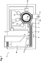
- FIGS. 1 to 3 a device 1 for filling containers 2 described in detail.
- the device described in the exemplary embodiment is used to fill containers 2 with a pharmaceutical liquid and comprises a ramp 10, on which the empty containers 2 slide down to a conveyor screw 11.
- the auger 11 conveys the empty containers in the direction of arrow A to a feed station 7.1 on a circular linear drive assembly 3.
- the various stations are in FIG. 1 each indicated by a reference numeral 7.x.
- the linear drive assembly 3 comprises a circular closed run 4 and a plurality of rotors 6, which are moved along the route 4 from station to station. This is in FIG. 1 indicated by the arrow B. Permanent magnets 5 are arranged on the rotors 6 and a coil is arranged on the running path 4, so that the rotors can be moved individually on the running track 4.
- both a forward and a backward movement of the rotor 6 is possible.
- FIG. 1 in addition to the supply station 7.1, a plurality of further stations along the circumference of the linear drive assembly 3 is provided.
- Reference numeral 7.2 denotes a firing station for opening the empty, closed container 2.
- the thus opened empty containers 2 are filled in a filling station 7.3 with the pharmaceutical liquid.
- a weighing station is integrated and the filling station is followed by a labeling station 7.4.
- the containers are moved to a capping station 7.5, in which on the one hand caps are towed for closing the filled containers, which are crimped on the containers 2 at the same time.
- 7.6 denotes a dispensing station for dispensing the filled and closed containers 2, which is indicated by the arrow C.
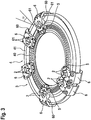
- the rotor 6 in addition to the permanent magnet 5 also rollers 60, which run on a running area 41 of the running track 4.
- the running track 4 further comprises a drive region 40, the running region 41 being at an angle ⁇ to the drive region 40 is arranged.
- the rotor 6 engage around the linear drive assembly 3 on the outer circumference, so that a stable and secure movement of the rotor 6 is possible.
- Each of the runners 6 comprises two receptacles 61, which serve to receive the containers 2.
- a control unit 8 which controls the runners 6, the individual stations 7 along the running path 4 and the screw conveyor 11.
- the control unit 8 is set up to control the individual runners individually.
- a starting process can be designed differently than in the case of still empty containers 2 in order to optimize a sloshing behavior of the liquid in the container 2.
- a transport star can thus be replaced by a circularly arranged linear drive arrangement with a closed running path 4.
- individual runners 6 can be moved either intermittently or continuously, depending on the desired requirements, between the stations.
- an individual transport of the containers 2 along the route 4 is possible without a process at one of the stations 7 specifies a minimum clock period.
Description
Die vorliegende Erfindung betrifft eine Vorrichtung zum Befüllen von Behältnissen mit einer Linearantriebsanordnung.The present invention relates to a device for filling containers with a linear drive arrangement.
Vorrichtungen zum Befüllen von Behältnissen werden beispielsweise im pharmazeutischen Bereich verwendet. In derartigen Befüllvorrichtungen werden üblicherweise sogenannte Transportsterne verwendet, wie beispielsweise aus der
Die erfindungsgemäße Vorrichtung zum Befüllen von Behältnissen mit den Merkmalen des Anspruchs 1 weist demgegenüber den Vorteil auf, dass gleichzeitig getaktete und kontinuierliche Bewegungen möglich sind. Insbesondere kann auch ein Schwappverhalten von mit Flüssigkeiten gefüllten Behältnissen verbessert werden, da individuelle Anlaufgeschwindigkeiten und Bremsgeschwindigkeiten von Station zu Station möglich sind. Darüber hinaus kann auf einfache Weise ein Puffer in der Vorrichtung bereitgestellt werden und es ist ein Leerstellenausgleich möglich. Die erfindungsgemäße Vorrichtung kann ferner einfacher aufgebaut sein und benötigt weniger Formatteile. Dies wird erfindungsgemäß dadurch erreicht, dass die Vorrichtung eine Linearantriebsanordnung mit einer geschlossenen Laufstrecke und einer Vielzahl von Läufern umfasst. Dabei sind an der Laufstrecke eine Vielzahl von Stationen einschließlich einer Füllstation zum Befüllen von Behältnissen angeordnet. Eine Steuereinheit ist vorgesehen, um die Läufer individuell anzutreiben und anzuhalten.The device according to the invention for filling containers with the features of claim 1 has the advantage over that simultaneously clocked and continuous movements are possible. In particular, a sloshing behavior of containers filled with liquids can also be improved, since individual startup speeds and braking speeds are possible from station to station. In addition, a buffer can easily be provided in the device and a vacancy compensation is possible. The device according to the invention can also be simpler in construction and requires fewer format parts. This is inventively achieved in that the device a Includes linear drive assembly with a closed track and a plurality of runners. In this case, a plurality of stations including a filling station for filling containers are arranged on the route. A control unit is provided to individually drive and stop the runners.
Weiterhin ist die geschlossenen und horizontal angeordnete Laufstrecke ein Kreis. Hierdurch kann erfindungsgemäß der Transportstern durch eine kreisförmige Linearantriebsanordnung ersetzt werden. Dabei kann trotzdem ein sehr kompakter und einfacher Aufbau der Vorrichtung erreicht werden.Furthermore, the closed and horizontally arranged running track is a circle. As a result, according to the invention, the transport star can be replaced by a circular linear drive arrangement. In this case, nevertheless, a very compact and simple construction of the device can be achieved.
Ferner umfassen die Läufer Gleitelemente oder Wälzkörper, welche auf der Laufstrecke gleiten oder rollen. Hierdurch wird eine reibungsarme Fortbewegung der Läufer auf der Laufstrecke erreicht.Furthermore, the runners comprise sliding elements or rolling elements which slide or roll on the running track. As a result, a low-friction movement of the runners is achieved on the running track.
Darüber hinaus umfasst die Laufstrecke einen Antriebsbereich der Linearantriebsanordnung und einen Laufbereich, wobei die Läufer, beispielsweise mit Gleitelementen oder Wälzkörpern, auf dem Laufbereich bewegt werden und wobei der Laufbereich in einem Winkel zum Antriebsbereich angeordnet ist. Der Winkel ist vorzugsweise ca. 25°.
Die Unteransprüche zeigen bevorzugte Weiterbildungen der Erfindung.
Um einen Puffer auf der Laufstrecke bereitzustellen, ist vorzugsweise eine Anzahl der Läufer um wenigstens 1 größer als eine Anzahl der Stationen an der Laufstrecke.
Weiter bevorzugt ist die Steuereinheit derart eingerichtet, dass Läufer rückwärts antreibbar sind. Hierdurch können Läufer beispielsweise für eine Nachbefüllung wieder zurück zur Füllstation gefahren werden und die Nachbefüllung ausgeführt werden.In addition, the running distance comprises a drive region of the linear drive arrangement and a running region, wherein the runners, for example with sliding elements or rolling elements, are moved on the running region and wherein the running region is arranged at an angle to the drive region. The angle is preferably about 25 °.
The dependent claims show preferred developments of the invention.
In order to provide a buffer on the route, preferably a number of runners is at least 1 greater than a number of the stations on the route.
More preferably, the control unit is set up such that runners can be driven backwards. As a result, runners can be driven back to the filling station for refilling, for example, and the refilling be carried out.
Gemäß der Erfindung weist jeder Läufer wenigstens zwei Aufnahmen zur Aufnahme von Behältnissen auf. Dadurch ist es möglich, dass pro Läufer eine Vielzahl von Behältnissen transportiert werden kann, wodurch die Ausbringung der Vorrichtung verbessert werden kann.According to the invention, each runner has at least two receptacles for receiving containers. That's it possible that a large number of containers can be transported per runner, whereby the output of the device can be improved.
Besonders bevorzugt umfasst die Vielzahl von Stationen eine Zufuhrstation zum Zuführen von leeren Behältnissen und/oder eine Wiegestation zum Wiegen von leeren und/oder befüllten Behältnissen, und/oder eine Aufbrennstation zum Öffnen von leeren, geschlossenen Behältnissen und/oder eine Kappenabschleppstation zum Abschleppen von Kappen und Aufsetzen der Kappen auf die befüllten Behältnisse und/oder eine Bördelstation zum Bördeln der Kappen an die Behältnisse und/oder eine Verschlussstation zum Verschließen der Behältnisse und/oder eine Abgabestation zum Abgeben der Behältnisse.Particularly preferably, the plurality of stations comprises a feed station for feeding empty containers and / or a weighing station for weighing empty and / or filled containers, and / or a firing station for opening empty, closed containers and / or a cap unloading station for towing caps and placing the caps on the filled containers and / or a crimping station for crimping the caps to the containers and / or a closure station for closing the containers and / or a dispensing station for dispensing the containers.
Die erfindungsgemäße Befüllvorrichtung wird erfindungsgemäß im pharmazeutischen Bereich und insbesondere zum Befüllen der Behältnisse mit einem flüssigen Medium verwendet. Hierbei ist die Steuereinheit erfindungsgemäß derart eingerichtet, dass an Stationen, an denen die mit Flüssigkeit befüllten Behältnisse wieder anfahren, ein Anfahrvorgang der Läufer mit einer geringeren Geschwindigkeit als bei Stationen, in denen noch leere Behältnisse bewegt werden, vorgesehen ist.The filling device according to the invention is used according to the invention in the pharmaceutical field and in particular for filling the containers with a liquid medium. In this case, the control unit according to the invention is set up such that at stations where the liquid-filled containers start again, a start-up of the rotor at a lower speed than at stations where empty containers are still moved, is provided.
Nachfolgend wird unter Bezugnahme auf die begleitende Zeichnung ein bevorzugtes Ausführungsbeispiel der Erfindung im Detail beschrieben. In der Zeichnung ist:
- Figur 1
- eine schematische Draufsicht einer Vorrichtung gemäß einem bevorzugten Ausführungsbeispiel der Erfindung,
Figur 2- eine schematische Draufsicht einer in
Figur 1 gezeigten Linearantriebsanordnung und - Figur 3
- eine perspektivische Ansicht der Linearantriebsanordnung.
- FIG. 1
- a schematic plan view of a device according to a preferred embodiment of the invention,
- FIG. 2
- a schematic plan view of an in
FIG. 1 shown linear drive assembly and - FIG. 3
- a perspective view of the linear drive assembly.
Nachfolgend wird unter Bezugnahme auf die
Die im Ausführungsbeispiel beschriebene Vorrichtung dient zum Befüllen von Behältnissen 2 mit einer pharmazeutischen Flüssigkeit und umfasst eine Rampe 10, auf welcher die leeren Behältnisse 2 nach unten zu einer Förderschnecke 11 rutschen. Die Förderschnecke 11 befördert die leeren Behältnisse in Richtung des Pfeils A zu einer Zufuhrstation 7.1 an einer kreisförmigen Linearantriebsanordnung 3. Die verschiedenen Stationen sind in
Wie insbesondere aus den
Wie aus
Wie insbesondere aus
Jeder der Läufer 6 umfasst zwei Aufnahmen 61, welche zum Aufnehmen der Behältnisse 2 dienen.Each of the
Wie insbesondere aus
Erfindungsgemäß kann somit ein Transportstern durch eine kreisförmig angeordnete Linearantriebsanordnung mit geschlossener Laufstrecke 4 ersetzt werden. Hierbei können einzelne Läufer 6 entweder taktweise oder kontinuierlich, je nach gewünschten Anforderungen, zwischen den Stationen bewegt werden. Somit ist ein individueller Transport der Behältnisse 2 entlang der Laufstrecke 4 möglich, ohne dass ein Vorgang an einer der Stationen 7 einen minimalen Taktzeitraum vorgibt.According to the invention, a transport star can thus be replaced by a circularly arranged linear drive arrangement with a
Claims (6)
- Apparatus for filling containers (2), comprising- a linear-drive arrangement (3) having a closed running path (4) and a multiplicity of runners (6) for accommodating and transporting the containers (2),- a multiplicity of stations (7), which are arranged on the running path (4), wherein the multiplicity of stations comprise at least one filling station (7.3) for filling the containers (2), and- a control unit (8), which is intended to drive, and to stop, the runners (6) individually,- wherein the runners (6) have sliding elements or rolling-contact bodies (60), which slide or roll on the running path (4),characterized in that- the apparatus is intended for filling containers (2) with a liquid medium in the pharmaceutical sector,- the closed running path (4) defines a circle and is arranged horizontally, and each runner (6) has at least two mounts (61) for accommodating the containers (2),- the running path (4) comprises a driving region (40) of the linear-drive arrangement (3) as well as a running region (41), wherein the running region (41) is arranged at an angle (α) to the driving region (40), and- the control unit (8) is intended such that, at stations at which runners (6) with liquid-filled containers (2) start up again, it controls a start-up operation of the runners (6) individually at a lower speed than in stations in which still-empty containers (2) are being moved.
- Apparatus according to Claim 1, characterized in that the angle (α) is approximately 25°.
- Apparatus according to either of the preceding claims, characterized in that the runners (6) engage around the outer circumference of the linear-drive arrangement (3).
- Apparatus according to one of the preceding claims, characterized in that the number of runners (6) is at least 1 greater than the number of stations (7).
- Apparatus according to one of the preceding claims, characterized in that the control unit (8) is intended to drive runners (6) backwards.
- Apparatus according to one of the preceding claims, characterized in that the multiplicity of stations also comprise a feeding station (7.1) for feeding empty containers (2) and/or a weighing station (7.4) for weighing empty and/or filled containers (2) and/or a burning-open station (7.2) for opening empty, closed containers (2) and/or a cap-recovery station (7.5) for recovering caps and positioning the caps on the filled containers (2) and/or a crimping station for crimping caps onto the container (2) and/or a closure station for closing the containers (2) and/or a discharging station (7.6) for discharging the containers (2).
Applications Claiming Priority (2)
| Application Number | Priority Date | Filing Date | Title |
|---|---|---|---|
| DE102012223173.0A DE102012223173A1 (en) | 2012-12-14 | 2012-12-14 | Device for filling containers with linear drive |
| PCT/EP2013/072002 WO2014090462A1 (en) | 2012-12-14 | 2013-10-22 | Apparatus for filling containers, having a linear drive |
Publications (2)
| Publication Number | Publication Date |
|---|---|
| EP2931633A1 EP2931633A1 (en) | 2015-10-21 |
| EP2931633B1 true EP2931633B1 (en) | 2017-08-02 |
Family
ID=49448165
Family Applications (1)
| Application Number | Title | Priority Date | Filing Date |
|---|---|---|---|
| EP13779844.3A Active EP2931633B1 (en) | 2012-12-14 | 2013-10-22 | Container filling machine provided with a linear drive |
Country Status (3)
| Country | Link |
|---|---|
| EP (1) | EP2931633B1 (en) |
| DE (1) | DE102012223173A1 (en) |
| WO (1) | WO2014090462A1 (en) |
Cited By (1)
| Publication number | Priority date | Publication date | Assignee | Title |
|---|---|---|---|---|
| DE102018207472A1 (en) * | 2018-05-15 | 2019-11-21 | Robert Bosch Gmbh | Device and method for transporting at least one object, in particular a pharmaceutical container, to several stations |
Families Citing this family (9)
| Publication number | Priority date | Publication date | Assignee | Title |
|---|---|---|---|---|
| DE102013216958A1 (en) * | 2013-08-26 | 2015-02-26 | Robert Bosch Gmbh | transfer device |
| ES2637746T3 (en) | 2015-01-19 | 2017-10-16 | Cama1 S.P.A. | A packing machine with a magnetic impeller conveyor |
| DE102016004335B4 (en) * | 2016-04-13 | 2018-10-11 | Fresenius Medical Care Deutschland Gmbh | Transport device and method for transporting objects from workstation to workstation of a production facility and production facility for the production of products with such a transportation facility |
| DE102017101331A1 (en) | 2017-01-24 | 2018-07-26 | Krones Ag | Container treatment plant and method for transporting functional elements in a container treatment plant for treating containers |
| DE102017115344A1 (en) * | 2017-07-10 | 2019-01-10 | Sig Technology Ag | Apparatus and method for delivering filled and sealed packages to an applicator |
| IT201800002628A1 (en) * | 2018-02-13 | 2019-08-13 | Gd Spa | Machine and method for filling cartridges for aerosol generators. |
| DE102018217777A1 (en) * | 2018-10-17 | 2020-04-23 | Krones Ag | Linear motor-operated transport system with a circular transport path and operation of the same |
| IT201900006834A1 (en) | 2019-05-14 | 2020-11-14 | Nuova Sima Spa | SORTING APPARATUS FOR SORTING AND STACKING TILES |
| IT201900006832A1 (en) * | 2019-05-14 | 2020-11-14 | Nuova Sima Spa | SORTING APPARATUS FOR SORTING AND STACKING TILES |
Citations (1)
| Publication number | Priority date | Publication date | Assignee | Title |
|---|---|---|---|---|
| DE102012103378A1 (en) * | 2012-04-18 | 2013-10-24 | Uhlmann Pac-Systeme Gmbh & Co Kg | Transport device with linear motor drive |
Family Cites Families (7)
| Publication number | Priority date | Publication date | Assignee | Title |
|---|---|---|---|---|
| SE9101060D0 (en) | 1991-04-09 | 1991-04-09 | Skf Specialty Product Ab | LINJAERENHET |
| US6876896B1 (en) * | 1999-04-26 | 2005-04-05 | Ab Tetrapak | Variable motion system and method |
| US6876107B2 (en) * | 2002-06-05 | 2005-04-05 | Jacobs Automation | Controlled motion system |
| GB0616458D0 (en) * | 2006-08-18 | 2006-09-27 | Meadwestvaco Packaging Systems | Metering apparatus with independent tool drive means |
| DE102009000496A1 (en) | 2009-01-30 | 2010-08-05 | Robert Bosch Gmbh | Transport device for the conveyance of goods |
| DE102010028055A1 (en) | 2010-04-21 | 2011-10-27 | Robert Bosch Gmbh | Transport device with improved runnability |
| DE102011016855B4 (en) * | 2011-04-13 | 2023-05-04 | Krones Aktiengesellschaft | Method and device for transporting containers or container bundles |
-
2012
- 2012-12-14 DE DE102012223173.0A patent/DE102012223173A1/en not_active Withdrawn
-
2013
- 2013-10-22 EP EP13779844.3A patent/EP2931633B1/en active Active
- 2013-10-22 WO PCT/EP2013/072002 patent/WO2014090462A1/en active Application Filing
Patent Citations (1)
| Publication number | Priority date | Publication date | Assignee | Title |
|---|---|---|---|---|
| DE102012103378A1 (en) * | 2012-04-18 | 2013-10-24 | Uhlmann Pac-Systeme Gmbh & Co Kg | Transport device with linear motor drive |
Cited By (1)
| Publication number | Priority date | Publication date | Assignee | Title |
|---|---|---|---|---|
| DE102018207472A1 (en) * | 2018-05-15 | 2019-11-21 | Robert Bosch Gmbh | Device and method for transporting at least one object, in particular a pharmaceutical container, to several stations |
Also Published As
| Publication number | Publication date |
|---|---|
| DE102012223173A1 (en) | 2014-06-18 |
| WO2014090462A1 (en) | 2014-06-19 |
| EP2931633A1 (en) | 2015-10-21 |
Similar Documents
| Publication | Publication Date | Title |
|---|---|---|
| EP2931633B1 (en) | Container filling machine provided with a linear drive | |
| DE102011016855B4 (en) | Method and device for transporting containers or container bundles | |
| EP2930129B1 (en) | Device for singulating and conveying upright containers | |
| EP2448820B1 (en) | Device for filling and sealing pharmaceutical containers | |
| EP3094590B1 (en) | Container-processing machine for processing containers | |
| EP3172134B1 (en) | Apparatus for transporting a container relative to a filling station | |
| EP2531440B1 (en) | Device and method for automatically shaping and filling containers | |
| EP2280873B1 (en) | Filling and sealing machine for containers | |
| EP3172819B1 (en) | Device for closing a receptacle | |
| WO2016012157A1 (en) | Device for filling a receptacle | |
| EP3038927B1 (en) | Method and device for producing packages | |
| DE102008046366A1 (en) | Centering unit for aligning at least two grouped vessels and method for aligning two grouped vessels | |
| EP3044137B1 (en) | Method and container conveyor for rearranging a container flow, and device having same | |
| EP2444363A1 (en) | Method and device for transporting container closures | |
| EP2933209B1 (en) | Method and device for transferring containers to a processing machine | |
| WO2013037541A1 (en) | Assembly for filling and sealing pharmaceutical containers, like small bottles, vials, or the like | |
| DE102014105974A1 (en) | Container treatment machine and method for treating containers | |
| DE102014114298A1 (en) | Container treatment device | |
| EP2154073A1 (en) | Method and device for metered filling of a number of containers | |
| DE102016122462A1 (en) | Device for sorting and conveying container closures | |
| DE10356073B4 (en) | Method and device for filling open-top beverage containers | |
| EP3838813A1 (en) | Device for feeding or discharging a container and container handling apparatus | |
| EP2421778B1 (en) | Product redistribution device | |
| DE102014110162A1 (en) | Apparatus and method for transporting a container at least partially filled with a filling product in a beverage filling plant | |
| EP2736835B1 (en) | Device for closing containers |
Legal Events
| Date | Code | Title | Description |
|---|---|---|---|
| PUAI | Public reference made under article 153(3) epc to a published international application that has entered the european phase |
Free format text: ORIGINAL CODE: 0009012 |
|
| 17P | Request for examination filed |
Effective date: 20150714 |
|
| AK | Designated contracting states |
Kind code of ref document: A1 Designated state(s): AL AT BE BG CH CY CZ DE DK EE ES FI FR GB GR HR HU IE IS IT LI LT LU LV MC MK MT NL NO PL PT RO RS SE SI SK SM TR |
|
| AX | Request for extension of the european patent |
Extension state: BA ME |
|
| TPAC | Observations filed by third parties |
Free format text: ORIGINAL CODE: EPIDOSNTIPA |
|
| DAX | Request for extension of the european patent (deleted) | ||
| 17Q | First examination report despatched |
Effective date: 20160415 |
|
| GRAP | Despatch of communication of intention to grant a patent |
Free format text: ORIGINAL CODE: EPIDOSNIGR1 |
|
| INTG | Intention to grant announced |
Effective date: 20170425 |
|
| RIC1 | Information provided on ipc code assigned before grant |
Ipc: B65G 47/86 20060101ALI20170410BHEP Ipc: B65G 29/00 20060101AFI20170410BHEP Ipc: B65B 7/28 20060101ALI20170410BHEP Ipc: B65B 3/04 20060101ALI20170410BHEP Ipc: B65G 54/02 20060101ALI20170410BHEP |
|
| GRAS | Grant fee paid |
Free format text: ORIGINAL CODE: EPIDOSNIGR3 |
|
| GRAA | (expected) grant |
Free format text: ORIGINAL CODE: 0009210 |
|
| AK | Designated contracting states |
Kind code of ref document: B1 Designated state(s): AL AT BE BG CH CY CZ DE DK EE ES FI FR GB GR HR HU IE IS IT LI LT LU LV MC MK MT NL NO PL PT RO RS SE SI SK SM TR |
|
| REG | Reference to a national code |
Ref country code: CH Ref legal event code: EP Ref country code: AT Ref legal event code: REF Ref document number: 914200 Country of ref document: AT Kind code of ref document: T Effective date: 20170815 |
|
| REG | Reference to a national code |
Ref country code: IE Ref legal event code: FG4D Free format text: LANGUAGE OF EP DOCUMENT: GERMAN |
|
| REG | Reference to a national code |
Ref country code: DE Ref legal event code: R096 Ref document number: 502013007956 Country of ref document: DE |
|
| REG | Reference to a national code |
Ref country code: FR Ref legal event code: PLFP Year of fee payment: 5 |
|
| REG | Reference to a national code |
Ref country code: NL Ref legal event code: MP Effective date: 20170802 |
|
| REG | Reference to a national code |
Ref country code: LT Ref legal event code: MG4D |
|
| PG25 | Lapsed in a contracting state [announced via postgrant information from national office to epo] |
Ref country code: NL Free format text: LAPSE BECAUSE OF FAILURE TO SUBMIT A TRANSLATION OF THE DESCRIPTION OR TO PAY THE FEE WITHIN THE PRESCRIBED TIME-LIMIT Effective date: 20170802 Ref country code: SE Free format text: LAPSE BECAUSE OF FAILURE TO SUBMIT A TRANSLATION OF THE DESCRIPTION OR TO PAY THE FEE WITHIN THE PRESCRIBED TIME-LIMIT Effective date: 20170802 Ref country code: NO Free format text: LAPSE BECAUSE OF FAILURE TO SUBMIT A TRANSLATION OF THE DESCRIPTION OR TO PAY THE FEE WITHIN THE PRESCRIBED TIME-LIMIT Effective date: 20171102 Ref country code: LT Free format text: LAPSE BECAUSE OF FAILURE TO SUBMIT A TRANSLATION OF THE DESCRIPTION OR TO PAY THE FEE WITHIN THE PRESCRIBED TIME-LIMIT Effective date: 20170802 Ref country code: FI Free format text: LAPSE BECAUSE OF FAILURE TO SUBMIT A TRANSLATION OF THE DESCRIPTION OR TO PAY THE FEE WITHIN THE PRESCRIBED TIME-LIMIT Effective date: 20170802 Ref country code: HR Free format text: LAPSE BECAUSE OF FAILURE TO SUBMIT A TRANSLATION OF THE DESCRIPTION OR TO PAY THE FEE WITHIN THE PRESCRIBED TIME-LIMIT Effective date: 20170802 |
|
| PG25 | Lapsed in a contracting state [announced via postgrant information from national office to epo] |
Ref country code: IS Free format text: LAPSE BECAUSE OF FAILURE TO SUBMIT A TRANSLATION OF THE DESCRIPTION OR TO PAY THE FEE WITHIN THE PRESCRIBED TIME-LIMIT Effective date: 20171202 Ref country code: ES Free format text: LAPSE BECAUSE OF FAILURE TO SUBMIT A TRANSLATION OF THE DESCRIPTION OR TO PAY THE FEE WITHIN THE PRESCRIBED TIME-LIMIT Effective date: 20170802 Ref country code: GR Free format text: LAPSE BECAUSE OF FAILURE TO SUBMIT A TRANSLATION OF THE DESCRIPTION OR TO PAY THE FEE WITHIN THE PRESCRIBED TIME-LIMIT Effective date: 20171103 Ref country code: LV Free format text: LAPSE BECAUSE OF FAILURE TO SUBMIT A TRANSLATION OF THE DESCRIPTION OR TO PAY THE FEE WITHIN THE PRESCRIBED TIME-LIMIT Effective date: 20170802 Ref country code: PL Free format text: LAPSE BECAUSE OF FAILURE TO SUBMIT A TRANSLATION OF THE DESCRIPTION OR TO PAY THE FEE WITHIN THE PRESCRIBED TIME-LIMIT Effective date: 20170802 Ref country code: BG Free format text: LAPSE BECAUSE OF FAILURE TO SUBMIT A TRANSLATION OF THE DESCRIPTION OR TO PAY THE FEE WITHIN THE PRESCRIBED TIME-LIMIT Effective date: 20171102 Ref country code: RS Free format text: LAPSE BECAUSE OF FAILURE TO SUBMIT A TRANSLATION OF THE DESCRIPTION OR TO PAY THE FEE WITHIN THE PRESCRIBED TIME-LIMIT Effective date: 20170802 |
|
| PG25 | Lapsed in a contracting state [announced via postgrant information from national office to epo] |
Ref country code: DK Free format text: LAPSE BECAUSE OF FAILURE TO SUBMIT A TRANSLATION OF THE DESCRIPTION OR TO PAY THE FEE WITHIN THE PRESCRIBED TIME-LIMIT Effective date: 20170802 Ref country code: RO Free format text: LAPSE BECAUSE OF FAILURE TO SUBMIT A TRANSLATION OF THE DESCRIPTION OR TO PAY THE FEE WITHIN THE PRESCRIBED TIME-LIMIT Effective date: 20170802 Ref country code: CZ Free format text: LAPSE BECAUSE OF FAILURE TO SUBMIT A TRANSLATION OF THE DESCRIPTION OR TO PAY THE FEE WITHIN THE PRESCRIBED TIME-LIMIT Effective date: 20170802 |
|
| REG | Reference to a national code |
Ref country code: DE Ref legal event code: R097 Ref document number: 502013007956 Country of ref document: DE |
|
| PG25 | Lapsed in a contracting state [announced via postgrant information from national office to epo] |
Ref country code: SM Free format text: LAPSE BECAUSE OF FAILURE TO SUBMIT A TRANSLATION OF THE DESCRIPTION OR TO PAY THE FEE WITHIN THE PRESCRIBED TIME-LIMIT Effective date: 20170802 Ref country code: SK Free format text: LAPSE BECAUSE OF FAILURE TO SUBMIT A TRANSLATION OF THE DESCRIPTION OR TO PAY THE FEE WITHIN THE PRESCRIBED TIME-LIMIT Effective date: 20170802 Ref country code: EE Free format text: LAPSE BECAUSE OF FAILURE TO SUBMIT A TRANSLATION OF THE DESCRIPTION OR TO PAY THE FEE WITHIN THE PRESCRIBED TIME-LIMIT Effective date: 20170802 Ref country code: MC Free format text: LAPSE BECAUSE OF FAILURE TO SUBMIT A TRANSLATION OF THE DESCRIPTION OR TO PAY THE FEE WITHIN THE PRESCRIBED TIME-LIMIT Effective date: 20170802 |
|
| PLBE | No opposition filed within time limit |
Free format text: ORIGINAL CODE: 0009261 |
|
| STAA | Information on the status of an ep patent application or granted ep patent |
Free format text: STATUS: NO OPPOSITION FILED WITHIN TIME LIMIT |
|
| 26N | No opposition filed |
Effective date: 20180503 |
|
| GBPC | Gb: european patent ceased through non-payment of renewal fee |
Effective date: 20171102 |
|
| REG | Reference to a national code |
Ref country code: IE Ref legal event code: MM4A |
|
| PG25 | Lapsed in a contracting state [announced via postgrant information from national office to epo] |
Ref country code: LU Free format text: LAPSE BECAUSE OF NON-PAYMENT OF DUE FEES Effective date: 20171022 |
|
| REG | Reference to a national code |
Ref country code: BE Ref legal event code: MM Effective date: 20171031 |
|
| PG25 | Lapsed in a contracting state [announced via postgrant information from national office to epo] |
Ref country code: BE Free format text: LAPSE BECAUSE OF NON-PAYMENT OF DUE FEES Effective date: 20171031 Ref country code: SI Free format text: LAPSE BECAUSE OF FAILURE TO SUBMIT A TRANSLATION OF THE DESCRIPTION OR TO PAY THE FEE WITHIN THE PRESCRIBED TIME-LIMIT Effective date: 20170802 |
|
| PG25 | Lapsed in a contracting state [announced via postgrant information from national office to epo] |
Ref country code: MT Free format text: LAPSE BECAUSE OF FAILURE TO SUBMIT A TRANSLATION OF THE DESCRIPTION OR TO PAY THE FEE WITHIN THE PRESCRIBED TIME-LIMIT Effective date: 20170802 |
|
| REG | Reference to a national code |
Ref country code: FR Ref legal event code: PLFP Year of fee payment: 6 |
|
| PG25 | Lapsed in a contracting state [announced via postgrant information from national office to epo] |
Ref country code: IE Free format text: LAPSE BECAUSE OF NON-PAYMENT OF DUE FEES Effective date: 20171022 |
|
| PG25 | Lapsed in a contracting state [announced via postgrant information from national office to epo] |
Ref country code: GB Free format text: LAPSE BECAUSE OF NON-PAYMENT OF DUE FEES Effective date: 20171102 |
|
| PG25 | Lapsed in a contracting state [announced via postgrant information from national office to epo] |
Ref country code: HU Free format text: LAPSE BECAUSE OF FAILURE TO SUBMIT A TRANSLATION OF THE DESCRIPTION OR TO PAY THE FEE WITHIN THE PRESCRIBED TIME-LIMIT; INVALID AB INITIO Effective date: 20131022 |
|
| PG25 | Lapsed in a contracting state [announced via postgrant information from national office to epo] |
Ref country code: CY Free format text: LAPSE BECAUSE OF FAILURE TO SUBMIT A TRANSLATION OF THE DESCRIPTION OR TO PAY THE FEE WITHIN THE PRESCRIBED TIME-LIMIT Effective date: 20170802 |
|
| PG25 | Lapsed in a contracting state [announced via postgrant information from national office to epo] |
Ref country code: MK Free format text: LAPSE BECAUSE OF FAILURE TO SUBMIT A TRANSLATION OF THE DESCRIPTION OR TO PAY THE FEE WITHIN THE PRESCRIBED TIME-LIMIT Effective date: 20170802 |
|
| REG | Reference to a national code |
Ref country code: AT Ref legal event code: MM01 Ref document number: 914200 Country of ref document: AT Kind code of ref document: T Effective date: 20181022 |
|
| PG25 | Lapsed in a contracting state [announced via postgrant information from national office to epo] |
Ref country code: AT Free format text: LAPSE BECAUSE OF NON-PAYMENT OF DUE FEES Effective date: 20181022 |
|
| PG25 | Lapsed in a contracting state [announced via postgrant information from national office to epo] |
Ref country code: TR Free format text: LAPSE BECAUSE OF FAILURE TO SUBMIT A TRANSLATION OF THE DESCRIPTION OR TO PAY THE FEE WITHIN THE PRESCRIBED TIME-LIMIT Effective date: 20170802 |
|
| PG25 | Lapsed in a contracting state [announced via postgrant information from national office to epo] |
Ref country code: PT Free format text: LAPSE BECAUSE OF FAILURE TO SUBMIT A TRANSLATION OF THE DESCRIPTION OR TO PAY THE FEE WITHIN THE PRESCRIBED TIME-LIMIT Effective date: 20170802 |
|
| REG | Reference to a national code |
Ref country code: DE Ref legal event code: R082 Ref document number: 502013007956 Country of ref document: DE Representative=s name: DREISS PATENTANWAELTE PARTG MBB, DE Ref country code: DE Ref legal event code: R081 Ref document number: 502013007956 Country of ref document: DE Owner name: SYNTEGON TECHNOLOGY GMBH, DE Free format text: FORMER OWNER: ROBERT BOSCH PACKAGING TECHNOLOGY GMBH, 71332 WAIBLINGEN, DE Ref country code: DE Ref legal event code: R081 Ref document number: 502013007956 Country of ref document: DE Owner name: SYNTEGON TECHNOLOGY GMBH, DE Free format text: FORMER OWNER: ROBERT BOSCH GMBH, 70469 STUTTGART, DE |
|
| PG25 | Lapsed in a contracting state [announced via postgrant information from national office to epo] |
Ref country code: AL Free format text: LAPSE BECAUSE OF FAILURE TO SUBMIT A TRANSLATION OF THE DESCRIPTION OR TO PAY THE FEE WITHIN THE PRESCRIBED TIME-LIMIT Effective date: 20170802 |
|
| REG | Reference to a national code |
Ref country code: CH Ref legal event code: PUE Owner name: SYNTEGON TECHNOLOGY GMBH, DE Free format text: FORMER OWNER: ROBERT BOSCH GMBH, DE |
|
| PGFP | Annual fee paid to national office [announced via postgrant information from national office to epo] |
Ref country code: IT Payment date: 20231031 Year of fee payment: 11 Ref country code: FR Payment date: 20231023 Year of fee payment: 11 Ref country code: DE Payment date: 20231018 Year of fee payment: 11 Ref country code: CH Payment date: 20231102 Year of fee payment: 11 |