EP2931616B1 - Behälteranordnung für füllgut - Google Patents
Behälteranordnung für füllgut Download PDFInfo
- Publication number
- EP2931616B1 EP2931616B1 EP13821799.7A EP13821799A EP2931616B1 EP 2931616 B1 EP2931616 B1 EP 2931616B1 EP 13821799 A EP13821799 A EP 13821799A EP 2931616 B1 EP2931616 B1 EP 2931616B1
- Authority
- EP
- European Patent Office
- Prior art keywords
- container
- container part
- locking
- arrangement
- closure
- Prior art date
- Legal status (The legal status is an assumption and is not a legal conclusion. Google has not performed a legal analysis and makes no representation as to the accuracy of the status listed.)
- Active
Links
- 239000000463 material Substances 0.000 title claims description 10
- 238000006073 displacement reaction Methods 0.000 claims description 2
- 239000013590 bulk material Substances 0.000 claims 1
- 238000011161 development Methods 0.000 description 4
- 230000018109 developmental process Effects 0.000 description 4
- 241000219198 Brassica Species 0.000 description 2
- 235000003351 Brassica cretica Nutrition 0.000 description 2
- 235000003343 Brassica rupestris Nutrition 0.000 description 2
- QKSKPIVNLNLAAV-UHFFFAOYSA-N bis(2-chloroethyl) sulfide Chemical compound ClCCSCCCl QKSKPIVNLNLAAV-UHFFFAOYSA-N 0.000 description 2
- 230000000295 complement effect Effects 0.000 description 2
- 238000013461 design Methods 0.000 description 2
- 235000010460 mustard Nutrition 0.000 description 2
- 238000007789 sealing Methods 0.000 description 2
- 239000002453 shampoo Substances 0.000 description 2
- 230000006978 adaptation Effects 0.000 description 1
- 238000004891 communication Methods 0.000 description 1
- 239000002131 composite material Substances 0.000 description 1
- 239000006071 cream Substances 0.000 description 1
- 230000001419 dependent effect Effects 0.000 description 1
- 230000000694 effects Effects 0.000 description 1
- 238000003780 insertion Methods 0.000 description 1
- 230000037431 insertion Effects 0.000 description 1
- 235000008960 ketchup Nutrition 0.000 description 1
- 239000007788 liquid Substances 0.000 description 1
- 239000006210 lotion Substances 0.000 description 1
- 235000010746 mayonnaise Nutrition 0.000 description 1
- 239000008268 mayonnaise Substances 0.000 description 1
- 238000000034 method Methods 0.000 description 1
- 239000000203 mixture Substances 0.000 description 1
- 238000000465 moulding Methods 0.000 description 1
- 235000011837 pasties Nutrition 0.000 description 1
- 239000007787 solid Substances 0.000 description 1
- 238000005507 spraying Methods 0.000 description 1
- 239000000126 substance Substances 0.000 description 1
- 230000000475 sunscreen effect Effects 0.000 description 1
- 239000000516 sunscreening agent Substances 0.000 description 1
Images


Classifications
-
- B—PERFORMING OPERATIONS; TRANSPORTING
- B65—CONVEYING; PACKING; STORING; HANDLING THIN OR FILAMENTARY MATERIAL
- B65D—CONTAINERS FOR STORAGE OR TRANSPORT OF ARTICLES OR MATERIALS, e.g. BAGS, BARRELS, BOTTLES, BOXES, CANS, CARTONS, CRATES, DRUMS, JARS, TANKS, HOPPERS, FORWARDING CONTAINERS; ACCESSORIES, CLOSURES, OR FITTINGS THEREFOR; PACKAGING ELEMENTS; PACKAGES
- B65D25/00—Details of other kinds or types of rigid or semi-rigid containers
- B65D25/38—Devices for discharging contents
-
- B—PERFORMING OPERATIONS; TRANSPORTING
- B65—CONVEYING; PACKING; STORING; HANDLING THIN OR FILAMENTARY MATERIAL
- B65D—CONTAINERS FOR STORAGE OR TRANSPORT OF ARTICLES OR MATERIALS, e.g. BAGS, BARRELS, BOTTLES, BOXES, CANS, CARTONS, CRATES, DRUMS, JARS, TANKS, HOPPERS, FORWARDING CONTAINERS; ACCESSORIES, CLOSURES, OR FITTINGS THEREFOR; PACKAGING ELEMENTS; PACKAGES
- B65D21/00—Nestable, stackable or joinable containers; Containers of variable capacity
- B65D21/02—Containers specially shaped, or provided with fittings or attachments, to facilitate nesting, stacking, or joining together
- B65D21/0201—Containers specially shaped, or provided with fittings or attachments, to facilitate nesting, stacking, or joining together stackable or joined together side-by-side
- B65D21/0204—Containers specially shaped, or provided with fittings or attachments, to facilitate nesting, stacking, or joining together stackable or joined together side-by-side and joined together by interconnecting formations forming part of the container, e.g. dove-tail, snap connections, hook elements
-
- B—PERFORMING OPERATIONS; TRANSPORTING
- B65—CONVEYING; PACKING; STORING; HANDLING THIN OR FILAMENTARY MATERIAL
- B65D—CONTAINERS FOR STORAGE OR TRANSPORT OF ARTICLES OR MATERIALS, e.g. BAGS, BARRELS, BOTTLES, BOXES, CANS, CARTONS, CRATES, DRUMS, JARS, TANKS, HOPPERS, FORWARDING CONTAINERS; ACCESSORIES, CLOSURES, OR FITTINGS THEREFOR; PACKAGING ELEMENTS; PACKAGES
- B65D11/00—Containers having bodies formed by interconnecting or uniting two or more rigid, or substantially rigid, components made wholly or mainly of plastics material
- B65D11/20—Details of walls made of plastics material
-
- B—PERFORMING OPERATIONS; TRANSPORTING
- B65—CONVEYING; PACKING; STORING; HANDLING THIN OR FILAMENTARY MATERIAL
- B65D—CONTAINERS FOR STORAGE OR TRANSPORT OF ARTICLES OR MATERIALS, e.g. BAGS, BARRELS, BOTTLES, BOXES, CANS, CARTONS, CRATES, DRUMS, JARS, TANKS, HOPPERS, FORWARDING CONTAINERS; ACCESSORIES, CLOSURES, OR FITTINGS THEREFOR; PACKAGING ELEMENTS; PACKAGES
- B65D21/00—Nestable, stackable or joinable containers; Containers of variable capacity
- B65D21/02—Containers specially shaped, or provided with fittings or attachments, to facilitate nesting, stacking, or joining together
- B65D21/0209—Containers specially shaped, or provided with fittings or attachments, to facilitate nesting, stacking, or joining together stackable or joined together one-upon-the-other in the upright or upside-down position
- B65D21/023—Closed containers provided with local cooperating elements in the top and bottom surfaces, e.g. projection and recess
- B65D21/0231—Bottles, canisters or jars whereby the neck or handle project into a cooperating cavity in the bottom
-
- B—PERFORMING OPERATIONS; TRANSPORTING
- B65—CONVEYING; PACKING; STORING; HANDLING THIN OR FILAMENTARY MATERIAL
- B65D—CONTAINERS FOR STORAGE OR TRANSPORT OF ARTICLES OR MATERIALS, e.g. BAGS, BARRELS, BOTTLES, BOXES, CANS, CARTONS, CRATES, DRUMS, JARS, TANKS, HOPPERS, FORWARDING CONTAINERS; ACCESSORIES, CLOSURES, OR FITTINGS THEREFOR; PACKAGING ELEMENTS; PACKAGES
- B65D21/00—Nestable, stackable or joinable containers; Containers of variable capacity
- B65D21/02—Containers specially shaped, or provided with fittings or attachments, to facilitate nesting, stacking, or joining together
- B65D21/0237—Rigid or semi-rigid containers provided with a recess on their external surface for accommodating a smaller container
-
- B—PERFORMING OPERATIONS; TRANSPORTING
- B65—CONVEYING; PACKING; STORING; HANDLING THIN OR FILAMENTARY MATERIAL
- B65D—CONTAINERS FOR STORAGE OR TRANSPORT OF ARTICLES OR MATERIALS, e.g. BAGS, BARRELS, BOTTLES, BOXES, CANS, CARTONS, CRATES, DRUMS, JARS, TANKS, HOPPERS, FORWARDING CONTAINERS; ACCESSORIES, CLOSURES, OR FITTINGS THEREFOR; PACKAGING ELEMENTS; PACKAGES
- B65D43/00—Lids or covers for rigid or semi-rigid containers
- B65D43/14—Non-removable lids or covers
-
- B—PERFORMING OPERATIONS; TRANSPORTING
- B65—CONVEYING; PACKING; STORING; HANDLING THIN OR FILAMENTARY MATERIAL
- B65D—CONTAINERS FOR STORAGE OR TRANSPORT OF ARTICLES OR MATERIALS, e.g. BAGS, BARRELS, BOTTLES, BOXES, CANS, CARTONS, CRATES, DRUMS, JARS, TANKS, HOPPERS, FORWARDING CONTAINERS; ACCESSORIES, CLOSURES, OR FITTINGS THEREFOR; PACKAGING ELEMENTS; PACKAGES
- B65D81/00—Containers, packaging elements, or packages, for contents presenting particular transport or storage problems, or adapted to be used for non-packaging purposes after removal of contents
- B65D81/32—Containers, packaging elements, or packages, for contents presenting particular transport or storage problems, or adapted to be used for non-packaging purposes after removal of contents for packaging two or more different materials which must be maintained separate prior to use in admixture
- B65D81/3205—Separate rigid or semi-rigid containers joined to each other at their external surfaces
-
- B—PERFORMING OPERATIONS; TRANSPORTING
- B65—CONVEYING; PACKING; STORING; HANDLING THIN OR FILAMENTARY MATERIAL
- B65D—CONTAINERS FOR STORAGE OR TRANSPORT OF ARTICLES OR MATERIALS, e.g. BAGS, BARRELS, BOTTLES, BOXES, CANS, CARTONS, CRATES, DRUMS, JARS, TANKS, HOPPERS, FORWARDING CONTAINERS; ACCESSORIES, CLOSURES, OR FITTINGS THEREFOR; PACKAGING ELEMENTS; PACKAGES
- B65D81/00—Containers, packaging elements, or packages, for contents presenting particular transport or storage problems, or adapted to be used for non-packaging purposes after removal of contents
- B65D81/32—Containers, packaging elements, or packages, for contents presenting particular transport or storage problems, or adapted to be used for non-packaging purposes after removal of contents for packaging two or more different materials which must be maintained separate prior to use in admixture
- B65D81/3216—Rigid containers disposed one within the other
Definitions
- the present invention relates to a container arrangement for filling goods, comprising at least two separate container parts with at least one each own, closable removal opening.
- a container arrangement which comprises a first and a second container part.
- Each container part has a separate removal opening.
- the container parts can be connected to one another such that the removal opening of the first container part point in a first direction and the removal opening of the second container part in a second direction.
- a container arrangement which comprises two container parts which can be emptied by a common removal opening.
- the two container parts are separably connected. When connected, they form a single bottle.
- the contents of the two container parts can only be emptied through a common opening, with a problem that can mix the two contents of the two container parts during the removal process in an undesirable manner.
- a container assembly comprising an inner container part and an outer container part
- the inner container part can be arranged in the interior of the outer container part and detachably fastened in one of two removal openings of the outer container part.
- the removal openings of the inner and the outer container part can be closed by closure parts, wherein the closure part of the inner container part is designed as a sealing ring which can be inserted into the corresponding removal opening of the outer container part.
- the object of the present invention is to provide a container assembly comprising at least two container parts, which are connected to each other in a simple manner, at the same time the contents of the container parts are also separated in the connected state of the same removed.
- the present container arrangement for filling comprises at least a first, separate container part with a closable removal opening and a second independent container part with a closable removal opening, wherein the second container part in a recess of the first container part detachable can be arranged, such that the first container part and the second container part are connectable to the container assembly.
- the first removal opening and the second removal opening point in different directions.
- the first removal opening can be closed by a first closure part and the second removal opening can be closed by a second closure part.
- At least the second closure part simultaneously engages over a portion of the second container part and the first container part locking when the first and the second container part are connected to each other.
- the essential advantage of the container arrangement according to the invention is that the two container parts are quickly and easily connected to each other, so that they can be transported and handled together as a unit or separately from each other depending on the application and handling. It is only necessary for locking, the second container part in the Insert or insert recess of the first container part and attach or attach the closure part of the second container part.
- the two container parts of the present container arrangement are preferably suitable for receiving solid, liquid, gelatinous, pasty or even gaseous substances.
- the following combinations may be included in the container parts of a container assembly: shampoo - conditioner, shampoo - shower gel, shower gel - exfoliant, baby oil - baby lotion, sunscreen - aftersun cream, mustard ketchup, mustard mayonnaise.
- the container parts of the present container assembly by various features, for. B. by color, lettering and transparency, to make different to visually identify the contents contained in the container parts and to point out the contents.
- the container parts of the present container arrangement may also have different shapes and sizes depending on the application. It is possible that the interconnected container parts have the overall shape and shape of a product already established on the market. In this way, a harmonious adaptation to any existing design can be made, and it can be avoided that shoppers must reorient themselves to certain shapes and sizes of products and get used to new shapes and sizes.
- the container parts can then be compressed and emptied independently of each other, even if the container parts are interconnected.
- the container parts may consist of different materials and / or different material thicknesses, so that in particular the squeezability of the material or the respective container part for the removal of the filling material may be different.
- the pressure to be exerted for the pressure can be adjusted individually to the contents contained in a container part or to its viscosity.
- the container parts can have different dimensions or volumes, so that it is conceivable to match the material components contained in the container parts, which are to be mixed with one another after removal in predetermined proportions, to one another.
- containing this contents container part can be placed with its closure part on a corresponding shelf.
- the present invention allows brand names, product information or advertising information on the contents contained in the container parts to be mounted on only one side of the container, so that the presentation of the contents on the shelf of the reseller visually greatly simplified and improved.
- the container arrangement has a uniformly closed cross section, preferably a cylindrical cross section, when the first container part is connected to the second container part.
- the first removal opening and the second removal opening of a present, particularly easy-to-handle container arrangement arranged coaxially to each other.
- the second container part is preferably fixed with the aid of positive and / or positive and / or cohesive locking elements in the recess for producing a particularly stable container arrangement.
- the first container part has a wall partially delimiting the recess and the second closure part comprises a locking arrangement which locks on a latching arrangement arranged on an end region of the wall of the first container part and on a latching arrangement arranged on the wall of the second container part engages when the second container part is inserted into the recess of the first container part and when the closure part is arranged at the removal opening of the second container part.
- the locking arrangement of the second closure part particularly preferably in the form of at least one arranged on the inside of the second closure part locking projection (or at least one locking groove) and the locking arrangement of the wall has the shape of at least one arranged on the outside of the wall locking groove (or at least one locking projection ) on.
- the locking arrangement of the wall of the second container part has zeckiquesce the shape of at least one arranged on the outside of the wall of the second container part locking groove (or at least one locking projection).
- the recess extends from the side of the first closure member to the side of the second closure member and has first closure part of the first container part on a locking arrangement, which is arranged on a arranged on the end region of the wall of the first container part further locking arrangement and on a arranged on the wall of the second container part further locking arrangement lockingly engages when the second container part is inserted into the recess of the first container part and when the first closure part is arranged at the removal opening of the first container part.
- the first container part has the recess limiting, opposite with respect to the longitudinal axis of the first container part leg portions and the second closure part on a locking arrangement, which arranged on the end portions of the leg parts locking arrangements and on one of the second container part arranged locking arrangement engages interlockingly when the second container part is inserted into the recess of the first container part and when the second closure part is arranged at the removal opening of the second container part.
- the locking arrangement of the second closure part and the locking arrangements of the leg parts and the locking arrangement of the second container part preferably form a snap closure or screw closure which is particularly easy to handle.
- the first container part between the leg parts on an additional container part which partially fills the recess between the leg portions of the first container part and in a recess of the second container part, between a first leg portion and a to this with respect to the Longitudinal axis of the container assembly opposite second leg portion is formed, engages when the first container part is connected to the second container part.
- the second container part between its leg parts on an additional container part which partially fills the recess between the leg portions of the second container part and engages in the recess of the first container part, when the first container part is connected to the second container part.
- the first closure part has a locking arrangement which engages lockingly on locking arrangements arranged on the end regions of the leg parts of the second container part and on the first container part, when the second container part is inserted into the recess of the first container part and when the first closure part is arranged at the removal opening of the first container part.
- the recess of the first container part, in which the second container part is inserted, laterally adjacent to an extension part of the first container part and the second container part has an extension part which engages in a further recess of the first container part.
- the extension part of the first container part simultaneously engages in a further recess of the second container part when the first container part and the second container part are connected to one another.
- the extension part of the first container part has at its end portion facing the second closure part a locking arrangement which is attached to the locking arrangement of the second closure part lockingly engages and the second container part has a locking arrangement which engages lockingly on the locking arrangement of the second closure parts when the second closure part of the second container part is arranged at the removal opening of the second container part.
- the extension part of the second container part may have a locking arrangement on its end part facing the first closure part, which lockingly engages on the locking arrangement of the first closure part and on the first container part has a locking arrangement which engages lockingly on the locking arrangement of the first closure part, if the first Closing part of the first container part is arranged at the removal opening of the first container part.
- the locking arrangement of the second closure part has the shape of at least one locking projection arranged on the inside of the second closure part or at least one Locking groove on and has the locking arrangement of the leg parts or the extension part of the first container part in the form of at least one on the outer sides of the leg parts oran the outer side of the extension part of the first container part arranged locking groove or at least one locking projection.
- the locking arrangement of the first closure part has the shape of at least one locking projection arranged on the inside of the first closure part or at least one locking groove
- the locking arrangement of the leg parts or the extension part of the second container part has the shape of at least one on the outer sides of the leg parts of the second container part .an on the outside of the extension part of the second container part arranged locking groove or at least one locking projection.
- the further recesses or the extension parts may be opposite each other with respect to the longitudinal axis of the container arrangement or they may alternatively be offset by 90 ° to each other when the first container part is connected to the second container part. Even with these, the extension parts comprehensive container arrangements, the container parts can be dimensioned so that they are identical and can be produced with one and the same shape of a plastic material.
- the second container part may have fixing elements on its side facing the first container part and the first container part on its side facing the second container part, which prevent a displacement of the first and second container part transversely to the longitudinal axis of the container arrangement ,
- These fixing elements may preferably have the form of mutually engaging Fixierschrägen or axially interlocking projections and recesses.
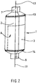
- the present container assembly 1 comprises a container part 2 and a container part 3. At the respective end faces of the container parts 2 and 3 are Closing parts 10 and 11 arranged.
- the closure part 10 has a cover part 21 on its front side. Accordingly, the closure part 11 on its front side on a cover part 12.
- the container part 3 is arranged in a depression or recess 8 of the container part 2.
- the two composite container parts 2 and 3 form the container assembly 1, which preferably has a uniform, closed cross-section 5.
- the container parts 2 and 3 are opposite by about 180 ° and arranged coaxially with each other.
- the cover part 12 or 21 is preferably attached by means of the aid of a hinge member 27 to the closure member 10 and 11 pivotally.
- a pin-shaped plug part 29 is preferably arranged on the side of the cover part 12 or 21 facing the closure part 10 or 11, which in the closed state of the cover part 12 or 21 into the opening 27 of the closure part 10 or 11 engages to seal the container part 2 and 3 sealingly.
- the container assembly 1 has a total of a cylindrical, preferably circular cylindrical shape. For storage, it is perpendicular to the end face of the cover part 12 or 21 adjustable
- Other cross-sectional shapes, in particular cylindrical cross-sectional shapes, such as rectangular or oval cross-sectional shapes are conceivable.
- the Fig. 1 and 2 show the container parts 2 and 3 in the interconnected, the container assembly 1 forming state.
- the container part 3 is arranged in the recess 8 of the container part 2, wherein the wall of the container part 3 with the wall of the recess 8 of the container part 2 can be positively and / or non-positively and / or materially connected.
- the reference numeral 22 ( Fig. 3 ) designates merely exemplary locking elements that serve the non-positive locking of the container part 3 on the container part 2
- the container part 2 has according to Fig. 2 a removal opening 7, which is offset from the removal opening 9 of the container part 3 by 180 °.
- the removal openings 7 and 9 are arranged coaxially with each other.
- a locking arrangement is arranged, which can effect a connection between the closure part 10 and the container part 2.
- the locking arrangement preferably has the form of a locking groove 13, which extends in the circumferential direction of the container part 2.
- locking projections are preferably arranged on the inside of the closure part 10, which can engage or snap into the locking groove 13 of the container part 2.
- Other locking arrangements such as screw or snap connections, are conceivable.
- the removal opening 9 of the container part 3 has a locking arrangement, preferably also a locking groove 14 which extends in the region of the removal opening 9 on the outer circumference the container assembly 1 extends partially over the container part 3 and partly also over the container part 2 in the circumferential direction. It is thereby achieved that when fastening the closure part 11 according to FIG. 1 the two container parts 2 and 3 are automatically firmly connected to each other when the container part 3 is inserted into the recess 8 of the container part 2.
- Other connection arrangements, such as screw or snap connections are conceivable, provided they fulfill the described function.
- FIG. 3 shows a longitudinal section along the longitudinal axis 17 of the container assembly 1.
- the container part 3 is arranged in the recess 8 of the container part 2.
- the portion or circumference 36 of the wall portion 20 of the container part 2 is located on the complementary portion 37 of the wall 21 of the container part 3.
- the closure parts 10 and 11 engage over the removal openings 7 and 9 of the container parts 2 and 3, respectively, and that the already explained locking grooves 13 and 14 extend radially to the longitudinal axis 17 of the container arrangement 1 along the outer circumference of the container part 2 (locking groove 13). and on the outer circumference of the container part 3 and the container part 2 (locking groove 14) extend.
- the locking groove 14 extends radially to the longitudinal axis 17 of the container assembly 1 along the wall parts 20 and 21. It is also conceivable that the recess 8 in a further development of the invention extends the entire length of the container part 2 and that the container part 3 is locked in the region of the closure part 11 in the region of the closure part 10 in accordance with the explained locking in the region of the closure part 11.
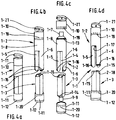
- a more specific embodiment of the container assembly 1-1 according to the invention comprises a first container part 1-2, a second container part 1-3, and a first closure part 1-10 and a second closure part 1-11.
- the first container part 1-2 comprises a recess 1-4 into which the second container part 1-3 can be inserted in such a way that the two container parts 1-2 and 1-3 form the container arrangement 1-1, preferably with a shaped body having a uniform cross section ,
- the recess 1-4 of the first container part 1-2 is formed by two transverse to the longitudinal direction of the first container part 1-2 spaced leg portions 1-5 and 1-6, wherein the leg portions 1-5 and 1-6 at the removal opening 1-7 ( Fig. 4c ) of the first container part 1-2 facing side by a connecting portion 1-8 of the first container part 1-2 are connected to each other.
- the recess 1-4 opens to the removal opening 1-7 side facing away such that the container part 1-3 can be inserted from this side into the recess 1-4.
- the second container part 1-3 has seen in the insertion direction at its the removal opening 1-7 of the first container part 1-2 side facing away from a removal opening 1-9 ( Fig. 4c ) on.
- the second container part 1-3 at its side facing the first container part 1-2 side, the second container part 1-3 in the particular of the Figures 1b and 1c apparent, preferably Fixierschrägen 1-15, which, when the container part 1-3 is fully inserted into the recess 1-4 of the container part 1-2, respectively on a complementary to a Fixierschräge 1-15 formed Fixierschräge 1-17 of the first Attack container part 1-2.
- the Fixierschrägen 1-17 are in particular from the Figure 1d seen.
- the Fixierschrägen 1-15 and the associated Fixierschrägen 1-17 Prevent when the second container part 1-3 is completely inserted into the first container part 1-2, that the two container parts in the region of the Fixierschrägen 1-15 and 1-17 transverse to the longitudinal axis of the container parts 1-2 and 1-3 against each other move. It should be noted that instead of the Fixierschrägen 1-15 and 1-17 also other fixing devices may be provided.
- the first container part 1-2 facing the end of the second container part 1-3 may be conical and engage in a corresponding recess of the first container part 1-2.
- the removal opening 1-7 of the first container part 1-2 can be closed by the closure part 1-10.
- the removal opening 1-9 of the second container part 1-3 can be closed by the closure part 1-11.
- the closure part 1-10 can be fastened to the first container part 1-2 with the aid of a connection arrangement, preferably a snap closure.
- the first container part 1-2 preferably has on its side facing the closure part 1-10 a locking groove 1-13 extending in the circumferential direction (FIG. Fig. 4c ), in which for locking the closure part 1-10 latching projections 1-19 can be latched, which are located on the inner circumference of the preferably ring-shaped closure part 1-10.
- latching projections 1-19 are located on the inner circumference of the preferably ring-shaped closure part 1-10.
- Locking grooves 1-16 which also extend in the circumferential direction.
- the locking grooves 1-14 and 1-16 are preferably designed so that when the second container part 1-3 is fully inserted into the first container part 1-2, they form a total circumferential groove, in which for locking the closure part 1-11 locking projections 1-20 engage, which are located on the inside of the preferably ring-shaped closure part 1-11.
- a significant advantage of the invention consists in the fact that the second container part 1-3 is automatically locked to the first container part 1-2 when it is completely inserted into the first container part 1-2 and the locking projections 1-20 when closing the removal opening 1- 9 ( Fig. 4c ) engage in the mutually aligned to a circumferential groove locking grooves 1-14 and 1-16. It should be noted that it is also possible to provide the locking projections 1-20 on the leg parts 1-5 and 1-6 and the Verriegelungsnutenl-16 on the closure part 1-11. There are also other locking devices, such as screw and snap connections in this area conceivable.
- FIGS. 5a to 5c a further embodiment of the container assembly according to the invention 2-1 explained, in which the container part 2-2 substantially to that of the container assembly of FIGS. 4a to 4c equivalent.
- the container part 2-2 differs from the container part 1-2 of FIGS. 4a to 4c only by the fact that the Recess 2-4 between the leg portions 2-5 and 2-6 of the container part 2-2 is partially filled by an additional container part 2-22, which encloses a volume which is in communication with the volume of the container part 2-2. In this way it is achieved that the container part 2-2 a larger total volume than that of the container part 1-2 of Fig. 4a to 1d includes.
- the container part 2-3 has a recess 2-21, in which the additional container part 2-22 is then completely absorbed when the container parts 2-2 and 2-3 connected to each other.
- the arrangement of the depression 2-21 in the container part 2-3 causes the container part 2-3 likewise has two leg portions 2-23 and 2-24 delimiting the recess 2-22 on opposite sides, which on the outer sides of the additional container part 2-22 abut when the container parts 2-2 and 2-3 are connected to each other and form the molding with a uniformly closed cross-section.
- the leg parts 2-5 and 2-6 of the container part 2-2 are opposite to the leg parts 2-23 and 2-24 of the container part 2-3 in the circumferential direction of the container assembly 2-1 seen offset by 90 ° to each other.
- the additional container part 2-21 serves as a guide for the container part 2-3.
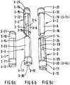
- FIGS. 6a to 6c a further embodiment of the inventive container assembly 3-1 explained, which is essentially that of FIGS. 5a to 5c equivalent.
- the difference to the container arrangement 2-1 consists only in that each container part 3-2 and 3-3 between its leg parts 3-5 and 3-6 or 3-23 and 3-24 an additional container part 3-22 or 3-3. 25 ( Fig. 6c ), each of which projects into the corresponding recess 3-4 or 3-21 between the leg portions 3-5 and 3-6 and 3-23 and 3-24 and at the same time also the respective leg portions 3-5 and 3 Forms -6 and 3-23 and 3-24 connecting cross members.
- the additional container parts 3-22 and 3-25 are preferably of the same size, so that the container arrangement 3-1 comprises two equal-sized container parts 3-2 and 3-3.
- the container arrangement 3-1 comprises two equal-sized container parts 3-2 and 3-3.
- the leg parts 3-23, 3-24 of the container part 3-3 preferably have at their end portions facing the container part 3-2 locking grooves 3-14 (or locking projections) which cooperate with the locking projections (or locking grooves) of the closure part 3-10.
- locking grooves 3-14 or locking projections
- the Fig. 7a to 7d show a further embodiment of the present container assembly 4-1, which substantially the embodiment of the Fig. 6a to 6c
- each container part 4-2 and 4-3 has only one leg part or an extension part 4-5 or 4-25.
- the extension parts 4-5 and 4-25 respectively project beyond the actual container part 4-2 or 4-3 in the longitudinal direction of the container arrangement 4-1.
- the container part 4-2 forms or comprises, in addition to the extension part 4-5, a recess 4-4 for receiving the container part 4-3 and a further recess 4-6 (FIG. Fig. 4d ) for receiving the extension part 4-25 of the container part 4-3.
- the container part 4-3 forms, in addition to the extension part 4-25, a recess 4-26 for receiving the container part 4-2 and a further recess 4-26 (FIG. Fig. 4b, c ) for receiving the extension part 4-5 of the container part 4-2.
- the end portions of the extension parts 4-5 and 4-25 have locking elements, preferably the locking grooves 4-16 and 4-14, which in the manner described above with further locking elements, preferably the locking projections 4-19 and 4-20, respectively interact. All others already related to the Fig. 6a to 6c explained elements (eg, closure parts 4-10, 4-11, the cover parts 4-12, 4-21, locking projections 4-19, 4-20, locking grooves 4-13, 4-14, 4-16) may be formed accordingly. The alternatives described above are conceivable.
- FIG. 7a to 7d and 8a to 8d An advantage of the developments of the invention according to the Fig. 7a to 7d and 8a to 8d is that the two container parts 4-2, 4-3 or 5-2, 5-3 may each be identical, so that they can be produced with one and the same shape, which leads to significant cost savings.
- the illustrated leg parts and extension parts are preferably suitable for receiving corresponding filling goods.
- the described container arrangements according to the invention consist of a plastic material which can be processed by spraying.
Landscapes
- Engineering & Computer Science (AREA)
- Mechanical Engineering (AREA)
- Closures For Containers (AREA)
- Stackable Containers (AREA)
Priority Applications (1)
| Application Number | Priority Date | Filing Date | Title |
|---|---|---|---|
| PL13821799T PL2931616T3 (pl) | 2012-12-12 | 2013-12-11 | Układ pojemników na wsad |
Applications Claiming Priority (3)
| Application Number | Priority Date | Filing Date | Title |
|---|---|---|---|
| DE102012112195.8A DE102012112195A1 (de) | 2012-12-12 | 2012-12-12 | Behältereinheit für Füllgut |
| DE202012104848U DE202012104848U1 (de) | 2012-12-12 | 2012-12-12 | Behältereinheit für Füllgut |
| PCT/EP2013/076277 WO2014090897A1 (de) | 2012-12-12 | 2013-12-11 | Behälteranordnung für füllgut |
Publications (2)
| Publication Number | Publication Date |
|---|---|
| EP2931616A1 EP2931616A1 (de) | 2015-10-21 |
| EP2931616B1 true EP2931616B1 (de) | 2017-02-08 |
Family
ID=49998194
Family Applications (1)
| Application Number | Title | Priority Date | Filing Date |
|---|---|---|---|
| EP13821799.7A Active EP2931616B1 (de) | 2012-12-12 | 2013-12-11 | Behälteranordnung für füllgut |
Country Status (9)
| Country | Link |
|---|---|
| US (1) | US9731867B2 (pl) |
| EP (1) | EP2931616B1 (pl) |
| JP (1) | JP6266011B2 (pl) |
| CN (1) | CN104884357B (pl) |
| BR (1) | BR112015013220A2 (pl) |
| DE (2) | DE202012104848U1 (pl) |
| ES (1) | ES2624407T3 (pl) |
| PL (1) | PL2931616T3 (pl) |
| WO (1) | WO2014090897A1 (pl) |
Families Citing this family (8)
| Publication number | Priority date | Publication date | Assignee | Title |
|---|---|---|---|---|
| DE102010052225A1 (de) * | 2010-11-24 | 2012-05-24 | Jean Paul Corbeil | Behälteranordnung |
| USD799335S1 (en) * | 2016-05-19 | 2017-10-10 | Caitlin Dimond | Bottle |
| EP3366599A1 (en) * | 2017-02-24 | 2018-08-29 | Corpack GmbH | Multi-volume container and method for producing a multi-volume container |
| USD913802S1 (en) * | 2019-10-29 | 2021-03-23 | Davinia Elaine Tang | Cosmetic bottle |
| US20220002025A1 (en) * | 2020-07-03 | 2022-01-06 | Ryan Benson | Dual mouth shotgun can |
| US12139301B2 (en) * | 2022-02-12 | 2024-11-12 | Jaclyn Nicole Andberg | Segmented shortwise container volume apparatus |
| USD1096413S1 (en) * | 2023-12-14 | 2025-10-07 | Shenzhen Kean Silicone Product Co., Ltd. | Bottle |
| CN117985321B (zh) * | 2024-04-03 | 2024-06-04 | 山东妙迪食品有限公司 | 一种可改变容积的海产品运输容器 |
Family Cites Families (17)
| Publication number | Priority date | Publication date | Assignee | Title |
|---|---|---|---|---|
| DE2237307A1 (de) | 1972-07-26 | 1974-02-14 | Abram Mamrud | Doppelflasche |
| US3856138A (en) * | 1973-05-31 | 1974-12-24 | Shionogi & Co | Compartmentalized container |
| US4573595A (en) | 1983-12-12 | 1986-03-04 | Universal Symetrics Corporation | Mated container units |
| US4640423A (en) * | 1985-04-09 | 1987-02-03 | Universal Symetrics Corporation | Multiple variable container package |
| US4673094A (en) * | 1986-09-22 | 1987-06-16 | Universal Symetrics Corporation | Large stub spout bottles and mated combination unit |
| US5954213A (en) | 1996-12-27 | 1999-09-21 | Lever Brothers Company | Dual container and individual chamber therefor |
| US6145685A (en) * | 1999-07-26 | 2000-11-14 | Surluster Inc. | Combination container |
| DE20115233U1 (de) * | 2001-09-14 | 2002-05-29 | Pickel, Roger, 45721 Haltern | Getränkedose mit einem "Zwei-Kammer-System" |
| US20060108363A1 (en) * | 2003-09-15 | 2006-05-25 | Yates William M Iii | Source selecting cap and closure for multiple chamber bottles |
| DE202005008852U1 (de) | 2005-06-07 | 2006-10-12 | Pagel, Katja | Vorrichtung mit einem wenigstens zwei Aufnahmekammern aufweisenden Flaschenkörper |
| JP2007055681A (ja) | 2005-08-25 | 2007-03-08 | Kohei Ueda | ジョイントハーフボトル容器 |
| US20070090077A1 (en) * | 2005-10-03 | 2007-04-26 | Graber Loren R | Container arrangement |
| CN200957903Y (zh) * | 2006-09-28 | 2007-10-10 | 姜敢华 | 一种双口瓶 |
| CN201287869Y (zh) * | 2008-09-01 | 2009-08-12 | 阿迪力江·许克尔 | 方便双口瓶 |
| BRMU9000405U2 (pt) | 2010-03-26 | 2015-01-06 | Neli Das Neves Guiguer | Embalagem dupla com aspecto de peça única para acondicionamento de dois produtos diferentes e/ou afins |
| DE102010052225A1 (de) | 2010-11-24 | 2012-05-24 | Jean Paul Corbeil | Behälteranordnung |
| TW201307164A (zh) * | 2011-08-12 | 2013-02-16 | Zi-Yuan Shen | 多腔室多開口容器 |
-
2012
- 2012-12-12 DE DE202012104848U patent/DE202012104848U1/de not_active Expired - Lifetime
- 2012-12-12 DE DE102012112195.8A patent/DE102012112195A1/de not_active Withdrawn
-
2013
- 2013-12-11 ES ES13821799.7T patent/ES2624407T3/es active Active
- 2013-12-11 JP JP2015547004A patent/JP6266011B2/ja not_active Expired - Fee Related
- 2013-12-11 WO PCT/EP2013/076277 patent/WO2014090897A1/de not_active Ceased
- 2013-12-11 PL PL13821799T patent/PL2931616T3/pl unknown
- 2013-12-11 US US14/650,588 patent/US9731867B2/en active Active
- 2013-12-11 CN CN201380064794.1A patent/CN104884357B/zh active Active
- 2013-12-11 BR BR112015013220A patent/BR112015013220A2/pt not_active IP Right Cessation
- 2013-12-11 EP EP13821799.7A patent/EP2931616B1/de active Active
Non-Patent Citations (1)
| Title |
|---|
| None * |
Also Published As
| Publication number | Publication date |
|---|---|
| BR112015013220A2 (pt) | 2017-07-11 |
| WO2014090897A1 (de) | 2014-06-19 |
| US20150344185A1 (en) | 2015-12-03 |
| CN104884357A (zh) | 2015-09-02 |
| DE102012112195A1 (de) | 2014-06-12 |
| PL2931616T3 (pl) | 2017-08-31 |
| JP6266011B2 (ja) | 2018-01-24 |
| US9731867B2 (en) | 2017-08-15 |
| JP2016505456A (ja) | 2016-02-25 |
| EP2931616A1 (de) | 2015-10-21 |
| CN104884357B (zh) | 2017-06-09 |
| ES2624407T3 (es) | 2017-07-14 |
| DE202012104848U1 (de) | 2013-03-19 |
Similar Documents
| Publication | Publication Date | Title |
|---|---|---|
| EP2931616B1 (de) | Behälteranordnung für füllgut | |
| EP2605858B1 (de) | Abgabemodul und verfahren zum befüllen eines abgabemoduls | |
| DE69323798T2 (de) | Nachfüllbarer Mehrkammer-Spender | |
| EP2768620B1 (de) | Kartusche und mehrkomponentenkartusche | |
| EP2747900B1 (de) | Mischer und abgabeeinrichtung | |
| EP2848320B1 (de) | Zwischenstück zur Verbindung eines Vorratsbehälters mit einem statischen Mischer | |
| EP2768619B1 (de) | Mehrkomponentenkartusche | |
| EP2605857B1 (de) | Abgabemodul | |
| DE102010049378B4 (de) | Kartuschenanordnung mit einer Doppelkartusche | |
| EP2823881B1 (de) | Vorrichtung und Verfahren zum Lagern und Mischen von Knochenzement | |
| EP3102503B1 (de) | Kartusche und verfahren zum herstellen einer kartusche | |
| DE19500782A1 (de) | Vorrichtung zum Mischen und Ausbringen einer Formmasse | |
| DE202005001203U1 (de) | Mehrkomponentenfolienbehälter | |
| WO2013056872A1 (de) | Kartusche, verfahren zur herstellung einer solchen, sowie mehrkomponentenkartusche | |
| EP2001430B1 (de) | System zum zubereiten und bereitstellen eines durch vermischen einer trockensubstanz mit einem fluid gebildeten fliessfähigen mediums | |
| DE69312510T2 (de) | Nachfüllbarer mehrkammer-spender und nachfüllpatrone | |
| DE102005002850B4 (de) | Vorrichtung zum Lagern und Austragen fluider Substanzen | |
| EP1671696B1 (de) | Statikmischelement zum Mischen fliessfähiger Massen | |
| DE202013011600U1 (de) | Portabler Mischbehälter mit zum Mischen von Getränkekomponenten verdreh- und/oder verschiebbaren Behälterteilen | |
| DE10310162A1 (de) | Kartusche zum Ausbringen von ein oder mehreren Komponenten einer Masse | |
| DE102008007306A1 (de) | Auspressvorrichtung für plastische Massen | |
| EP4301500B1 (de) | Mischelement für einen statischen mixer | |
| DE102012209985B4 (de) | Adapterartige Vorrichtung zur Kopplung zweier Behälter | |
| EP3774581B1 (de) | Applikationssystem mit verbesserter dichtung | |
| DE102010030402A1 (de) | Kartusche zum Auspressen von Füllsubstanzen |
Legal Events
| Date | Code | Title | Description |
|---|---|---|---|
| PUAI | Public reference made under article 153(3) epc to a published international application that has entered the european phase |
Free format text: ORIGINAL CODE: 0009012 |
|
| 17P | Request for examination filed |
Effective date: 20150630 |
|
| AK | Designated contracting states |
Kind code of ref document: A1 Designated state(s): AL AT BE BG CH CY CZ DE DK EE ES FI FR GB GR HR HU IE IS IT LI LT LU LV MC MK MT NL NO PL PT RO RS SE SI SK SM TR |
|
| AX | Request for extension of the european patent |
Extension state: BA ME |
|
| DAX | Request for extension of the european patent (deleted) | ||
| GRAP | Despatch of communication of intention to grant a patent |
Free format text: ORIGINAL CODE: EPIDOSNIGR1 |
|
| INTG | Intention to grant announced |
Effective date: 20161026 |
|
| GRAS | Grant fee paid |
Free format text: ORIGINAL CODE: EPIDOSNIGR3 |
|
| STAA | Information on the status of an ep patent application or granted ep patent |
Free format text: STATUS: GRANT OF PATENT IS INTENDED |
|
| GRAA | (expected) grant |
Free format text: ORIGINAL CODE: 0009210 |
|
| STAA | Information on the status of an ep patent application or granted ep patent |
Free format text: STATUS: THE PATENT HAS BEEN GRANTED |
|
| AK | Designated contracting states |
Kind code of ref document: B1 Designated state(s): AL AT BE BG CH CY CZ DE DK EE ES FI FR GB GR HR HU IE IS IT LI LT LU LV MC MK MT NL NO PL PT RO RS SE SI SK SM TR |
|
| REG | Reference to a national code |
Ref country code: GB Ref legal event code: FG4D Free format text: NOT ENGLISH |
|
| REG | Reference to a national code |
Ref country code: CH Ref legal event code: EP Ref country code: AT Ref legal event code: REF Ref document number: 866756 Country of ref document: AT Kind code of ref document: T Effective date: 20170215 |
|
| REG | Reference to a national code |
Ref country code: IE Ref legal event code: FG4D Free format text: LANGUAGE OF EP DOCUMENT: GERMAN |
|
| REG | Reference to a national code |
Ref country code: DE Ref legal event code: R096 Ref document number: 502013006342 Country of ref document: DE |
|
| REG | Reference to a national code |
Ref country code: CH Ref legal event code: NV Representative=s name: ABREMA AGENCE BREVET ET MARQUES, GANGUILLET, CH |
|
| REG | Reference to a national code |
Ref country code: NL Ref legal event code: FP |
|
| REG | Reference to a national code |
Ref country code: LT Ref legal event code: MG4D |
|
| REG | Reference to a national code |
Ref country code: ES Ref legal event code: FG2A Ref document number: 2624407 Country of ref document: ES Kind code of ref document: T3 Effective date: 20170714 |
|
| PG25 | Lapsed in a contracting state [announced via postgrant information from national office to epo] |
Ref country code: LT Free format text: LAPSE BECAUSE OF FAILURE TO SUBMIT A TRANSLATION OF THE DESCRIPTION OR TO PAY THE FEE WITHIN THE PRESCRIBED TIME-LIMIT Effective date: 20170208 Ref country code: GR Free format text: LAPSE BECAUSE OF FAILURE TO SUBMIT A TRANSLATION OF THE DESCRIPTION OR TO PAY THE FEE WITHIN THE PRESCRIBED TIME-LIMIT Effective date: 20170509 Ref country code: FI Free format text: LAPSE BECAUSE OF FAILURE TO SUBMIT A TRANSLATION OF THE DESCRIPTION OR TO PAY THE FEE WITHIN THE PRESCRIBED TIME-LIMIT Effective date: 20170208 Ref country code: NO Free format text: LAPSE BECAUSE OF FAILURE TO SUBMIT A TRANSLATION OF THE DESCRIPTION OR TO PAY THE FEE WITHIN THE PRESCRIBED TIME-LIMIT Effective date: 20170508 Ref country code: HR Free format text: LAPSE BECAUSE OF FAILURE TO SUBMIT A TRANSLATION OF THE DESCRIPTION OR TO PAY THE FEE WITHIN THE PRESCRIBED TIME-LIMIT Effective date: 20170208 |
|
| PG25 | Lapsed in a contracting state [announced via postgrant information from national office to epo] |
Ref country code: SE Free format text: LAPSE BECAUSE OF FAILURE TO SUBMIT A TRANSLATION OF THE DESCRIPTION OR TO PAY THE FEE WITHIN THE PRESCRIBED TIME-LIMIT Effective date: 20170208 Ref country code: PT Free format text: LAPSE BECAUSE OF FAILURE TO SUBMIT A TRANSLATION OF THE DESCRIPTION OR TO PAY THE FEE WITHIN THE PRESCRIBED TIME-LIMIT Effective date: 20170608 Ref country code: BG Free format text: LAPSE BECAUSE OF FAILURE TO SUBMIT A TRANSLATION OF THE DESCRIPTION OR TO PAY THE FEE WITHIN THE PRESCRIBED TIME-LIMIT Effective date: 20170508 Ref country code: LV Free format text: LAPSE BECAUSE OF FAILURE TO SUBMIT A TRANSLATION OF THE DESCRIPTION OR TO PAY THE FEE WITHIN THE PRESCRIBED TIME-LIMIT Effective date: 20170208 Ref country code: RS Free format text: LAPSE BECAUSE OF FAILURE TO SUBMIT A TRANSLATION OF THE DESCRIPTION OR TO PAY THE FEE WITHIN THE PRESCRIBED TIME-LIMIT Effective date: 20170208 |
|
| PG25 | Lapsed in a contracting state [announced via postgrant information from national office to epo] |
Ref country code: SK Free format text: LAPSE BECAUSE OF FAILURE TO SUBMIT A TRANSLATION OF THE DESCRIPTION OR TO PAY THE FEE WITHIN THE PRESCRIBED TIME-LIMIT Effective date: 20170208 Ref country code: EE Free format text: LAPSE BECAUSE OF FAILURE TO SUBMIT A TRANSLATION OF THE DESCRIPTION OR TO PAY THE FEE WITHIN THE PRESCRIBED TIME-LIMIT Effective date: 20170208 Ref country code: CZ Free format text: LAPSE BECAUSE OF FAILURE TO SUBMIT A TRANSLATION OF THE DESCRIPTION OR TO PAY THE FEE WITHIN THE PRESCRIBED TIME-LIMIT Effective date: 20170208 Ref country code: RO Free format text: LAPSE BECAUSE OF FAILURE TO SUBMIT A TRANSLATION OF THE DESCRIPTION OR TO PAY THE FEE WITHIN THE PRESCRIBED TIME-LIMIT Effective date: 20170208 |
|
| REG | Reference to a national code |
Ref country code: DE Ref legal event code: R097 Ref document number: 502013006342 Country of ref document: DE |
|
| PG25 | Lapsed in a contracting state [announced via postgrant information from national office to epo] |
Ref country code: SM Free format text: LAPSE BECAUSE OF FAILURE TO SUBMIT A TRANSLATION OF THE DESCRIPTION OR TO PAY THE FEE WITHIN THE PRESCRIBED TIME-LIMIT Effective date: 20170208 Ref country code: DK Free format text: LAPSE BECAUSE OF FAILURE TO SUBMIT A TRANSLATION OF THE DESCRIPTION OR TO PAY THE FEE WITHIN THE PRESCRIBED TIME-LIMIT Effective date: 20170208 |
|
| PLBE | No opposition filed within time limit |
Free format text: ORIGINAL CODE: 0009261 |
|
| STAA | Information on the status of an ep patent application or granted ep patent |
Free format text: STATUS: NO OPPOSITION FILED WITHIN TIME LIMIT |
|
| REG | Reference to a national code |
Ref country code: FR Ref legal event code: PLFP Year of fee payment: 5 |
|
| 26N | No opposition filed |
Effective date: 20171109 |
|
| PG25 | Lapsed in a contracting state [announced via postgrant information from national office to epo] |
Ref country code: SI Free format text: LAPSE BECAUSE OF FAILURE TO SUBMIT A TRANSLATION OF THE DESCRIPTION OR TO PAY THE FEE WITHIN THE PRESCRIBED TIME-LIMIT Effective date: 20170208 |
|
| PG25 | Lapsed in a contracting state [announced via postgrant information from national office to epo] |
Ref country code: LU Free format text: LAPSE BECAUSE OF NON-PAYMENT OF DUE FEES Effective date: 20171211 Ref country code: MT Free format text: LAPSE BECAUSE OF FAILURE TO SUBMIT A TRANSLATION OF THE DESCRIPTION OR TO PAY THE FEE WITHIN THE PRESCRIBED TIME-LIMIT Effective date: 20170208 |
|
| PG25 | Lapsed in a contracting state [announced via postgrant information from national office to epo] |
Ref country code: MC Free format text: LAPSE BECAUSE OF FAILURE TO SUBMIT A TRANSLATION OF THE DESCRIPTION OR TO PAY THE FEE WITHIN THE PRESCRIBED TIME-LIMIT Effective date: 20170208 Ref country code: HU Free format text: LAPSE BECAUSE OF FAILURE TO SUBMIT A TRANSLATION OF THE DESCRIPTION OR TO PAY THE FEE WITHIN THE PRESCRIBED TIME-LIMIT; INVALID AB INITIO Effective date: 20131211 |
|
| PG25 | Lapsed in a contracting state [announced via postgrant information from national office to epo] |
Ref country code: CY Free format text: LAPSE BECAUSE OF FAILURE TO SUBMIT A TRANSLATION OF THE DESCRIPTION OR TO PAY THE FEE WITHIN THE PRESCRIBED TIME-LIMIT Effective date: 20170208 |
|
| PG25 | Lapsed in a contracting state [announced via postgrant information from national office to epo] |
Ref country code: MK Free format text: LAPSE BECAUSE OF FAILURE TO SUBMIT A TRANSLATION OF THE DESCRIPTION OR TO PAY THE FEE WITHIN THE PRESCRIBED TIME-LIMIT Effective date: 20170208 |
|
| PG25 | Lapsed in a contracting state [announced via postgrant information from national office to epo] |
Ref country code: AL Free format text: LAPSE BECAUSE OF FAILURE TO SUBMIT A TRANSLATION OF THE DESCRIPTION OR TO PAY THE FEE WITHIN THE PRESCRIBED TIME-LIMIT Effective date: 20170208 Ref country code: IS Free format text: LAPSE BECAUSE OF FAILURE TO SUBMIT A TRANSLATION OF THE DESCRIPTION OR TO PAY THE FEE WITHIN THE PRESCRIBED TIME-LIMIT Effective date: 20170608 |
|
| REG | Reference to a national code |
Ref country code: CH Ref legal event code: PFUS Owner name: CORPACK GMBH, DE Free format text: FORMER OWNER: CORPACK GMBH, DE |
|
| PGFP | Annual fee paid to national office [announced via postgrant information from national office to epo] |
Ref country code: IE Payment date: 20211220 Year of fee payment: 9 Ref country code: AT Payment date: 20211216 Year of fee payment: 9 |
|
| PGFP | Annual fee paid to national office [announced via postgrant information from national office to epo] |
Ref country code: CH Payment date: 20211222 Year of fee payment: 9 Ref country code: BE Payment date: 20211217 Year of fee payment: 9 |
|
| PGFP | Annual fee paid to national office [announced via postgrant information from national office to epo] |
Ref country code: PL Payment date: 20211201 Year of fee payment: 9 Ref country code: NL Payment date: 20211217 Year of fee payment: 9 |
|
| REG | Reference to a national code |
Ref country code: DE Ref legal event code: R082 Ref document number: 502013006342 Country of ref document: DE Representative=s name: KARAKATSANIS, GEORGIOS, DR., DE |
|
| REG | Reference to a national code |
Ref country code: CH Ref legal event code: PL |
|
| REG | Reference to a national code |
Ref country code: NL Ref legal event code: MM Effective date: 20230101 |
|
| REG | Reference to a national code |
Ref country code: AT Ref legal event code: MM01 Ref document number: 866756 Country of ref document: AT Kind code of ref document: T Effective date: 20221211 |
|
| REG | Reference to a national code |
Ref country code: BE Ref legal event code: MM Effective date: 20221231 |
|
| PG25 | Lapsed in a contracting state [announced via postgrant information from national office to epo] |
Ref country code: NL Free format text: LAPSE BECAUSE OF NON-PAYMENT OF DUE FEES Effective date: 20230101 |
|
| PG25 | Lapsed in a contracting state [announced via postgrant information from national office to epo] |
Ref country code: LI Free format text: LAPSE BECAUSE OF NON-PAYMENT OF DUE FEES Effective date: 20221231 Ref country code: IE Free format text: LAPSE BECAUSE OF NON-PAYMENT OF DUE FEES Effective date: 20221211 Ref country code: CH Free format text: LAPSE BECAUSE OF NON-PAYMENT OF DUE FEES Effective date: 20221231 Ref country code: AT Free format text: LAPSE BECAUSE OF NON-PAYMENT OF DUE FEES Effective date: 20221211 |
|
| PG25 | Lapsed in a contracting state [announced via postgrant information from national office to epo] |
Ref country code: BE Free format text: LAPSE BECAUSE OF NON-PAYMENT OF DUE FEES Effective date: 20221231 |
|
| PGFP | Annual fee paid to national office [announced via postgrant information from national office to epo] |
Ref country code: DE Payment date: 20241205 Year of fee payment: 12 |
|
| PGFP | Annual fee paid to national office [announced via postgrant information from national office to epo] |
Ref country code: GB Payment date: 20241218 Year of fee payment: 12 |
|
| PGFP | Annual fee paid to national office [announced via postgrant information from national office to epo] |
Ref country code: FR Payment date: 20241219 Year of fee payment: 12 |
|
| PGFP | Annual fee paid to national office [announced via postgrant information from national office to epo] |
Ref country code: IT Payment date: 20241216 Year of fee payment: 12 |
|
| PGFP | Annual fee paid to national office [announced via postgrant information from national office to epo] |
Ref country code: TR Payment date: 20241203 Year of fee payment: 12 |
|
| PGFP | Annual fee paid to national office [announced via postgrant information from national office to epo] |
Ref country code: ES Payment date: 20250117 Year of fee payment: 12 |
|
| PG25 | Lapsed in a contracting state [announced via postgrant information from national office to epo] |
Ref country code: PL Free format text: LAPSE BECAUSE OF NON-PAYMENT OF DUE FEES Effective date: 20221211 |