EP2931127B1 - Interventionssystem - Google Patents
Interventionssystem Download PDFInfo
- Publication number
- EP2931127B1 EP2931127B1 EP13818811.5A EP13818811A EP2931127B1 EP 2931127 B1 EP2931127 B1 EP 2931127B1 EP 13818811 A EP13818811 A EP 13818811A EP 2931127 B1 EP2931127 B1 EP 2931127B1
- Authority
- EP
- European Patent Office
- Prior art keywords
- introduction element
- tracking
- generating unit
- image generating
- unit
- Prior art date
- Legal status (The legal status is an assumption and is not a legal conclusion. Google has not performed a legal analysis and makes no representation as to the accuracy of the status listed.)
- Active
Links
- 230000005855 radiation Effects 0.000 claims description 104
- 238000000034 method Methods 0.000 claims description 31
- 238000004590 computer program Methods 0.000 claims description 18
- 230000004044 response Effects 0.000 claims description 13
- 210000003484 anatomy Anatomy 0.000 description 6
- 238000013152 interventional procedure Methods 0.000 description 6
- 230000009466 transformation Effects 0.000 description 4
- 230000001419 dependent effect Effects 0.000 description 3
- 238000002059 diagnostic imaging Methods 0.000 description 3
- 230000009471 action Effects 0.000 description 2
- 230000007423 decrease Effects 0.000 description 2
- 238000010191 image analysis Methods 0.000 description 2
- 230000011218 segmentation Effects 0.000 description 2
- 238000012800 visualization Methods 0.000 description 2
- 229920003266 Leaf® Polymers 0.000 description 1
- 230000008901 benefit Effects 0.000 description 1
- 238000004364 calculation method Methods 0.000 description 1
- 230000002860 competitive effect Effects 0.000 description 1
- 238000013170 computed tomography imaging Methods 0.000 description 1
- 239000002872 contrast media Substances 0.000 description 1
- 238000001914 filtration Methods 0.000 description 1
- 238000002594 fluoroscopy Methods 0.000 description 1
- 238000002595 magnetic resonance imaging Methods 0.000 description 1
- 230000003287 optical effect Effects 0.000 description 1
- 230000008569 process Effects 0.000 description 1
- 230000001131 transforming effect Effects 0.000 description 1
Images

Classifications
-
- A—HUMAN NECESSITIES
- A61—MEDICAL OR VETERINARY SCIENCE; HYGIENE
- A61B—DIAGNOSIS; SURGERY; IDENTIFICATION
- A61B6/00—Apparatus or devices for radiation diagnosis; Apparatus or devices for radiation diagnosis combined with radiation therapy equipment
- A61B6/06—Diaphragms
-
- A—HUMAN NECESSITIES
- A61—MEDICAL OR VETERINARY SCIENCE; HYGIENE
- A61B—DIAGNOSIS; SURGERY; IDENTIFICATION
- A61B6/00—Apparatus or devices for radiation diagnosis; Apparatus or devices for radiation diagnosis combined with radiation therapy equipment
- A61B6/54—Control of apparatus or devices for radiation diagnosis
- A61B6/547—Control of apparatus or devices for radiation diagnosis involving tracking of position of the device or parts of the device
-
- A—HUMAN NECESSITIES
- A61—MEDICAL OR VETERINARY SCIENCE; HYGIENE
- A61B—DIAGNOSIS; SURGERY; IDENTIFICATION
- A61B34/00—Computer-aided surgery; Manipulators or robots specially adapted for use in surgery
- A61B34/30—Surgical robots
-
- A—HUMAN NECESSITIES
- A61—MEDICAL OR VETERINARY SCIENCE; HYGIENE
- A61B—DIAGNOSIS; SURGERY; IDENTIFICATION
- A61B34/00—Computer-aided surgery; Manipulators or robots specially adapted for use in surgery
- A61B34/30—Surgical robots
- A61B34/32—Surgical robots operating autonomously
-
- A—HUMAN NECESSITIES
- A61—MEDICAL OR VETERINARY SCIENCE; HYGIENE
- A61B—DIAGNOSIS; SURGERY; IDENTIFICATION
- A61B6/00—Apparatus or devices for radiation diagnosis; Apparatus or devices for radiation diagnosis combined with radiation therapy equipment
- A61B6/12—Arrangements for detecting or locating foreign bodies
-
- A—HUMAN NECESSITIES
- A61—MEDICAL OR VETERINARY SCIENCE; HYGIENE
- A61B—DIAGNOSIS; SURGERY; IDENTIFICATION
- A61B6/00—Apparatus or devices for radiation diagnosis; Apparatus or devices for radiation diagnosis combined with radiation therapy equipment
- A61B6/44—Constructional features of apparatus for radiation diagnosis
- A61B6/4429—Constructional features of apparatus for radiation diagnosis related to the mounting of source units and detector units
- A61B6/4435—Constructional features of apparatus for radiation diagnosis related to the mounting of source units and detector units the source unit and the detector unit being coupled by a rigid structure
- A61B6/4441—Constructional features of apparatus for radiation diagnosis related to the mounting of source units and detector units the source unit and the detector unit being coupled by a rigid structure the rigid structure being a C-arm or U-arm
-
- A—HUMAN NECESSITIES
- A61—MEDICAL OR VETERINARY SCIENCE; HYGIENE
- A61B—DIAGNOSIS; SURGERY; IDENTIFICATION
- A61B6/00—Apparatus or devices for radiation diagnosis; Apparatus or devices for radiation diagnosis combined with radiation therapy equipment
- A61B6/48—Diagnostic techniques
- A61B6/481—Diagnostic techniques involving the use of contrast agents
-
- A—HUMAN NECESSITIES
- A61—MEDICAL OR VETERINARY SCIENCE; HYGIENE
- A61B—DIAGNOSIS; SURGERY; IDENTIFICATION
- A61B6/00—Apparatus or devices for radiation diagnosis; Apparatus or devices for radiation diagnosis combined with radiation therapy equipment
- A61B6/48—Diagnostic techniques
- A61B6/486—Diagnostic techniques involving generating temporal series of image data
- A61B6/487—Diagnostic techniques involving generating temporal series of image data involving fluoroscopy
-
- A—HUMAN NECESSITIES
- A61—MEDICAL OR VETERINARY SCIENCE; HYGIENE
- A61B—DIAGNOSIS; SURGERY; IDENTIFICATION
- A61B6/00—Apparatus or devices for radiation diagnosis; Apparatus or devices for radiation diagnosis combined with radiation therapy equipment
- A61B6/54—Control of apparatus or devices for radiation diagnosis
-
- A—HUMAN NECESSITIES
- A61—MEDICAL OR VETERINARY SCIENCE; HYGIENE
- A61B—DIAGNOSIS; SURGERY; IDENTIFICATION
- A61B90/00—Instruments, implements or accessories specially adapted for surgery or diagnosis and not covered by any of the groups A61B1/00 - A61B50/00, e.g. for luxation treatment or for protecting wound edges
- A61B90/36—Image-producing devices or illumination devices not otherwise provided for
- A61B90/37—Surgical systems with images on a monitor during operation
-
- A—HUMAN NECESSITIES
- A61—MEDICAL OR VETERINARY SCIENCE; HYGIENE
- A61B—DIAGNOSIS; SURGERY; IDENTIFICATION
- A61B34/00—Computer-aided surgery; Manipulators or robots specially adapted for use in surgery
- A61B34/20—Surgical navigation systems; Devices for tracking or guiding surgical instruments, e.g. for frameless stereotaxis
- A61B2034/2046—Tracking techniques
- A61B2034/2065—Tracking using image or pattern recognition
-
- A—HUMAN NECESSITIES
- A61—MEDICAL OR VETERINARY SCIENCE; HYGIENE
- A61B—DIAGNOSIS; SURGERY; IDENTIFICATION
- A61B34/00—Computer-aided surgery; Manipulators or robots specially adapted for use in surgery
- A61B34/30—Surgical robots
- A61B2034/301—Surgical robots for introducing or steering flexible instruments inserted into the body, e.g. catheters or endoscopes
-
- A—HUMAN NECESSITIES
- A61—MEDICAL OR VETERINARY SCIENCE; HYGIENE
- A61B—DIAGNOSIS; SURGERY; IDENTIFICATION
- A61B90/00—Instruments, implements or accessories specially adapted for surgery or diagnosis and not covered by any of the groups A61B1/00 - A61B50/00, e.g. for luxation treatment or for protecting wound edges
- A61B90/36—Image-producing devices or illumination devices not otherwise provided for
- A61B2090/364—Correlation of different images or relation of image positions in respect to the body
- A61B2090/365—Correlation of different images or relation of image positions in respect to the body augmented reality, i.e. correlating a live optical image with another image
-
- A—HUMAN NECESSITIES
- A61—MEDICAL OR VETERINARY SCIENCE; HYGIENE
- A61B—DIAGNOSIS; SURGERY; IDENTIFICATION
- A61B90/00—Instruments, implements or accessories specially adapted for surgery or diagnosis and not covered by any of the groups A61B1/00 - A61B50/00, e.g. for luxation treatment or for protecting wound edges
- A61B90/36—Image-producing devices or illumination devices not otherwise provided for
- A61B90/37—Surgical systems with images on a monitor during operation
- A61B2090/376—Surgical systems with images on a monitor during operation using X-rays, e.g. fluoroscopy
- A61B2090/3762—Surgical systems with images on a monitor during operation using X-rays, e.g. fluoroscopy using computed tomography systems [CT]
- A61B2090/3764—Surgical systems with images on a monitor during operation using X-rays, e.g. fluoroscopy using computed tomography systems [CT] with a rotating C-arm having a cone beam emitting source
-
- A—HUMAN NECESSITIES
- A61—MEDICAL OR VETERINARY SCIENCE; HYGIENE
- A61B—DIAGNOSIS; SURGERY; IDENTIFICATION
- A61B6/00—Apparatus or devices for radiation diagnosis; Apparatus or devices for radiation diagnosis combined with radiation therapy equipment
- A61B6/50—Apparatus or devices for radiation diagnosis; Apparatus or devices for radiation diagnosis combined with radiation therapy equipment specially adapted for specific body parts; specially adapted for specific clinical applications
- A61B6/504—Apparatus or devices for radiation diagnosis; Apparatus or devices for radiation diagnosis combined with radiation therapy equipment specially adapted for specific body parts; specially adapted for specific clinical applications for diagnosis of blood vessels, e.g. by angiography
Definitions
- the invention relates to an interventional system comprising an introduction element like a catheter for being introduced into an object, a moving unit like a robot for moving the introduction element within the object and a tracking image generating unit for generating tracking images of the introduction element within the object.
- the invention relates further to a corresponding interventional computer program.
- the invention relates to a controlling method and a controlling computer program for controlling a radiation beam of the tracking image generating unit of the interventional system.
- US2006/0247520 discloses an interventional system comprising an imager and a catheter. Tracking means are used to monitor the motion of the catheter, and the motion data are used to control the position of the imager so that images of the targeted tissue region can be acquired.
- WO 2012/123850 A1 discloses a medical imaging device for providing an image representation which is used for positioning an interventional device within a region of interest during an interventional procedure. The medical imaging device is adapted to acquire a pre-live anatomy image including the region of interest, to acquire a live anatomy image including the region of interest by using a live image acquisition device comprising an adjustable collimator and to identify a location of the interventional device within the live anatomy image.
- the medical imaging device is further adapted to adjust settings of the collimator based on the identified location of the interventional device, to subsequently acquire a further live anatomy image including the region of interest by using the live image acquisition device with the adjusted collimator and to provide the image representation by merging information from the live anatomy image into the pre-live anatomy image.
- WO 2005/009243 A1 discloses an x-ray unit for generating images of a body, wherein the x-ray unit comprises an x-ray source, an automatically adjustable collimator for limiting, locally attenuating and/or filtering an x-ray beam, an x-ray detector and a data processing unit that is coupled to the collimator and the x-ray detector.
- the data processing unit is adapted to localize a region of interest inside the body on at least a first x-ray image of the body transmitted by the x-ray detector and to adjust the collimator such that subsequent x-ray images are concentrated on the region of interest.
- the x-ray unit is used for tracking a movement of a catheter tip within the body, i.e. if the region of interest is a moving region of interest defined by the moving catheter tip, and if this tracking is performed by acquiring a sequence of x-ray images, the x-ray source has to irradiate a relatively large region of the body, which corresponds to the largest distance the catheter tip can travel between consecutive x-ray images, in order to ensure that the catheter tip is really captured by the x-ray images and can therefore be tracked by using the x-ray unit.
- This relatively large irradiated region of the body results in a relatively large radiation dose applied to the body.
- the x-ray source is switched off for a short time and if the x-ray source is then switched on again, the location of the catheter tip is not known such that a relatively large part of the body has to be irradiated by the x-ray radiation, in order to find the moving catheter tip. Also this leads to a relatively large radiation dose.
- It is an object of the present invention to provide an interventional system comprising an introduction element like a catheter for being introduced into an object, a moving unit like a robot for moving the introduction element within the object and a tracking image generating unit for generating tracking images of the introduction element within the object, which allows for generating tracking images which surely show the introduction element, even if the introduction element moves, with a reduced radiation dose. It is a further object of the present invention to provide a corresponding interventional computer program, and to provide a controlling method and a controlling computer program for controlling a radiation beam of the tracking image generating unit of the interventional system.
- an interventional system comprising:
- the tracking image generating unit knows the real physical movement of the introduction element, which can be used by the controller for controlling the tracking image generating unit such that the radiation beam traverses a region of the object that includes the introduction element.
- This control of the radiation beam can be performed very accurately based on the known real physical movement of the introduction element such that it is not necessary to irradiate a relatively large area of the object for ensuring that the introduction element is really captured by the tracking images, thereby allowing for a reduced radiation dose applied to the object.
- the movement parameters define a movement of the tip of the introduction element within the object, wherein the controller is adapted to control the tracking image generating unit depending on the provided movement parameters such that the radiation beam traverses a region of the object that includes the tip of the introduction element.
- the introduction element is preferentially a catheter, a needle or another interventional instrument to be introduced into the object, which is preferentially a living object like a person or an animal.
- the moving unit is preferentially a robot for robotically moving the introduction element within the object, wherein this robotical movement can be performed automatically or by a user like a physician, who may control the moving unit via an input unit like a keyboard, a joystick, a touch screen, a mouse, et cetera.
- the tracking image generating unit is preferentially adapted to generate a sequence of tracking images showing the introduction element, while it moves within the object.
- the tracking image generating unit is adapted to generate x-ray images showing the introduction element within the object.
- the tracking image generating unit is, for instance, an x-ray C-arm unit.
- the tracking image generating unit preferentially comprises a collimator for collimating the radiation beam, wherein the controller is adapted to control the collimator such that the radiation beam is collimated depending on the provided movement parameters such that the radiation beam traverses a region of the object that includes the introduction element.
- the controller may be adapted to control the collimator depending on a speed of the movement as defined by the movement parameters and/or a response time of the interventional system.
- the controller can be adapted to control the collimator depending on the speed of the movement as defined by the movement parameters and/or the response time of the interventional system such that a part of the radiation beam, which is in front of the introduction element with respect to a movement direction defined by the movement parameters, increases with increasing speed and/or with increasing response time.
- the controller can be adapted to control the radiation beam by controlling the collimator of the tracking image generating unit.
- the controller can also be adapted to control other components of the tracking image generating unit for controlling the radiation beam like the radiation source and the radiation detector of the tracking image generating unit.
- the controller can be adapted to control the positions of these components for providing a desired direction of the radiation beam.
- the interventional system further comprises an identification unit for indentifying the introduction element in the generated tracking images, wherein the controller is adapted to control the tracking image generating unit depending on the identification of the introduction element in the generated tracking images.
- the controller is adapted to control the tracking image generating unit depending on the identification of the introduction element in the generated tracking images.
- the identification of the introduction element in the generated tracking images is indicative of the real physical position of the introduction element within the object. Using this information regarding the real physical position of the introduction element within the object obtained from the tracking images together with the movement parameters provided by the moving unit for controlling the tracking image generating unit, in particular, the radiation beam, further improves the quality of tracking the introduction element by using the tracking images.
- the identification of the introduction element in the tracking images can be used to control the direction of the radiation beam, for example, the radiation beam can be controlled such that the introduction element, in particular, the tip of the introduction element, is centrally located within the tracking images, wherein the width of the radiation beam can be controlled depending on the movement parameters.
- the identification unit is preferentially adapted to use known segmentation algorithms for segmenting the introduction element in the generated tracking images, in order to identify the introduction element.
- the interventional system may further comprise a position determination unit for determining the position of the introduction element within the object based on the movement parameters, wherein the controller can be adapted to control the tracking image generating unit depending on the determined position of the introduction element.
- the tracking image generating unit may comprise a collimator for collimating the radiation beam, wherein the position determination unit can be adapted to additionally determine an accuracy value being indicative of the accuracy of the determination of the position and wherein the controller can be adapted to control the collimator depending on the accuracy value.
- the controller is adapted to control the collimator such that the collimator has a narrower opening, if the accuracy value indicates a higher accuracy, and that the collimator has a wider opening, if the accuracy value indicates a lower accuracy.
- the accuracy value may be determined depending on, for instance, the speed of the movement defined by the movement parameters and/or depending on the total amount of movement defined by the movement parameters during a switch off period.
- the total amount of movement may be defined as being the total distance that the introduction element has travelled during the switch off period.
- the interventional system may further comprise a) a position determination unit for determining the position of the introduction element within the object based on the movement parameters, b) an object image providing unit for providing an object image showing the object, and c) a display for displaying the object image and a representation of the introduction element at the determined position of the introduction element in the object image.
- the object image can be an overview image showing a larger part of the object.
- the object image can be a roadmap image showing a vessel tree of a person, wherein the introduction element may be moved within a vessel of the vessel tree.
- the position of the introduction element within the object is determined based on the movement parameters, wherein a representation of the introduction element at the determined position of the introduction element in the object image, for instance, in the roadmap image, is shown on the display, the position of the introduction element within the object can be shown on the display, even if currently a tracking image is not generated. For instance, the tip of an introduction element can be shown within a roadmap image, even if a tracking image is currently not generated.
- the interventional system may also comprise a) an object image providing unit for providing an object image showing the object, b) an overlay image determining unit for determining an overlay image being an overlay of the object image and the target image, and c) a display for displaying the object image and the tracking image overlaid on each other.
- the object image can be, for instance, a roadmap image showing a vessel tree of a person. Since the tracking image shows the introduction element, by displaying the object image and the tracking image overlaid on each other, the position of the introduction element within the object can be shown to a user. Also in this embodiment the object image is preferentially an overview image showing a larger part of the object.
- a controller is presented, wherein the controller is adapted to control aradiation beam emitted by a radiation source of a tracking image generating unit depending on movement parameters provided by amoving unit for moving an introduction element within an object such that the radiation beam traverses a region of theobject that includes the introduction element.
- interventional method comprises:
- a controlling method for controlling a tracking image generating unit of an interventional system as defined in claim 1 comprises receiving movement parameters, which define a movement of an introduction element within an object, from a moving unit of the interventional system via a wired or wireless data connection and controlling the radiation beam depending on the received movement parameters provided by the moving unit such that the radiation beam traverses a region of the object that includes the introduction element.
- an interventional computer program which comprises program code means for causing an interventional system as defined in claim 1 to carry out the following steps, when the interventional computer program is run on a computer controlling the interventional system:
- a controlling computer program for controlling a radiation beam of a tracking image generating unit of an interventional system as defined in claim 1 comprises program code means for causing the controller of the tracking image generating unit to carry out the steps of the controlling method as defined in claim 11, when the controlling computer program is run on the controller.
- interventional system of claim 1 the controller, the interventional method, the controlling method of claim 11, the interventional computer program of claim 12, and the controlling computer program of claim 13 have similar and/or identical preferred embodiments, in particular, as defined in the dependent claims.
- Fig. 1 shows schematically and exemplarily an embodiment of an interventional system.
- the interventional system is a catheter system 1 for introducing a catheter 4 into a person 9 lying on a support means like a patient table 10.
- the catheter system 1 comprises a moving unit 2 for moving the catheter 4 within the person 9.
- the moving unit 2 is a robotic unit for robotically moving the catheter 4 within the person 9.
- the robotic unit 2 is controlled by a user like a physician via an input unit 26.
- the input unit 26 may comprise a joystick, a keyboard, a mouse, a touchpad or another means for allowing the user to control the movement of the robotic unit 2.
- the movement performed by the robotic unit 2 can be described by movement parameters, which may define a sequence of positions of the catheter 4, particularly of the tip of the catheter 4, within the person 9, and by corresponding time stamps such that for each position the respective time is known.
- the movement parameters are transferred from the robotic unit 2 to a tracking image generating unit 3.
- the tracking image generating unit 3 is adapted to generate several tracking images, which correspond to different times and which show the catheter 4, particularly the tip of the catheter 4, at different positions during the movement.
- the tracking image generating unit 3 is an x-ray C-arm system comprising an x-ray source 5 emitting an x-ray radiation beam 7 for traversing the person 9 with the catheter 4.
- the x-ray C-arm system 3 further comprises an x-ray detector 6 for detecting the radiation beam 7 after having traversed the person 9 with the catheter 4, and a controller 8 for controlling the radiation beam 7 and for generating x-ray projection images based on the radiation detected by the x-ray detector 6, wherein the generated x-ray projection images, i.e.
- the generated tracking images show the catheter 4, particularly the tip of the catheter 4, within the person 9 at different positions during the movement, i.e. several tracking images are generated, which correspond to different times during the movement of the tip of the catheter 4 within the person 9.
- the images can be provided to a display 27 for showing the same.
- the tracking image generating unit 3, i.e. the x-ray C-arm system 3, further comprises a collimator 20 for collimating the radiation beam 7, wherein the controller 8 is adapted to control the collimator 20 such that the radiation beam 7 is collimated depending on the provided movement parameters such that the radiation beam 7 traverses a region of the person 9 that includes the catheter 4, particularly the tip of the catheter 4.
- the controller 8 can be adapted to control the collimator 20 depending on the speed of the movement as defined by the movement parameters and/or a response time of the interventional system.
- the controller 8 can be adapted to control the collimator 20 depending on the speed of the movement as defined by the movement parameters and the response time of the interventional system 1 such that a part of the radiation beam 7, which is in front of the tip of the catheter 4 with respect to a movement direction defined by the movement parameters, increases with increasing speed and with increasing response time.
- the part of the radiation beam in front of the tip of the catheter 4 with respect to the movement direction defined by the movement parameters can be regarded as defining a safety margin. Since the movement parameters are used for controlling the safety margin, the safety margin can be smaller than a safety margin, which has to be used by a tracking image generating unit with a standard tight collimation technique as described in the above mentioned patent document WO 2005/009243 A1 .
- the safety margin i.e. in this example the part of the radiation beam in front of the tip of the catheter 4 with respect to the movement direction defined by the movement parameters, may be defined by following equation: S > v t r , wherein S represents the safety margin in front of the tip of the catheter 4, ⁇ represents the speed in the movement direction, i.e. the corresponding speed set point of the robotic unit 2, and t r represents the response time of the interventional system.
- the safety margin S and the speed ⁇ relate to quantities in the tracking images, i.e. S is a length in front of the tip of the catheter in the movement direction and ⁇ is the speed of the robotic unit as defined by the movement parameters with respect to an image reference frame defined by the tracking images, wherein the movement parameters, i.e. the velocity ⁇ defined by the movement parameters, have been transformed to correspond to the reference image frame.
- a transformation which can be used for transforming the movement parameters to the image reference frame, is described further below.
- the response time of the interventional system is preferentially defined as being the time between an action of motion of the introduction element within the person 9 and a control of the radiation beam in reaction of the action of motion. This response time depends on, for instance, the latency between the moving unit and the controller, the time needed by the collimator to react on inputs from the controller, et cetera.
- An identification unit 23 can identify the catheter 4 in the generated tracking image and the controller 8 can control the radiation beam 7 such that the identified catheter 4 is centrally located or at another position within the tracking image.
- the identification unit 23 can use known segmentation algorithms for identifying the catheter 4 within the tracking images.
- the collimation, i.e. the width of the radiation beam 7, can be determined based on the movement parameters, for instance, based on the speed of movement as defined by the movement parameters as described above.
- the interventional system can further comprise a position determination unit 22 for determining the position of the catheter 4, particularly of the tip of the catheter 4, within the person 9 based on the movement parameters, wherein the position determination unit 22 can be adapted to additionally determine an accuracy value being indicative of the accuracy of the determination of the position.
- This determined position and accuracy value is preferentially used for controlling the tracking image generating unit 3, if the tracking image generating unit 3 temporally does not generate tracking images, i.e. if the tracking image generating unit 3 is in a switch off period. This control is preferentially performed such that, if the generation of the tracking images is started again, the tracking images immediately show the tip of the catheter 4.
- the control is preferentially performed such that the collimator 20 has a narrower opening, if the accuracy value indicates a higher accuracy, and that the collimator 20 has a wider opening, if the accuracy value indicates a lower accuracy.
- the position determination unit 22 is preferentially adapted to determine the accuracy value depending on the speed of the movement defined by the movement parameters during the switch off period and/or the total amount of movement defined by the movement parameters during the switch off period, wherein with increasing speed and/or increasing total amount of movement, respectively, the accuracy value decreases.
- the accuracy value can also be a function of the switch off time, wherein with increasing switch off time the accuracy value may decrease.
- the accuracy value may also depend on results from calibration steps performed for calibrating the interventional system.
- the accuracy of determining the position of the introduction element within the object based on the movement parameters can be determined by determining this position several times based on the same movement parameters, wherein the accuracy can be estimated depending on the resulting distribution of determined positions.
- the accuracy value can be determined depending on the standard deviation of this distribution.
- the interventional system allows estimating the location of the catheter 4, even if the x-ray source 5 is switched off.
- the location of the catheter 4 can be determined based on the movement as defined by the movement parameters and based on a known location of the catheter, from which the catheter 4 has been moved away. This known location can be a location, which has been determined by using a tracking image and by identifying the catheter 4 in the tracking image. If the x-ray source 5 is temporally switched off, this location of the catheter 4 determined by using the movement parameters can be used to control the components of the tracking image generating unit 3 defining the direction and shape of the radiation beam like the collimator 20 such that they follow the estimated location of the catheter 4. If then the x-ray source 5 is switched on again, the tracking image will capture the catheter 4 already very well, wherein the capturing of the catheter 4 can then be refined based on the generated tracking image.
- the controller 8 comprises the position determination unit 22 and the identification unit 23.
- these units can also be arranged in another part of the interventional system 1, for instance, in another processing unit like the processing unit 11, which in this embodiment comprises an object image providing unit 24 for providing an object image showing the person 9.
- the object image providing unit 24 is adapted to provide an overview image preferentially including roadmap information showing vessels along which the catheter 4 can be moved within the person 9.
- the object image providing unit 24 is therefore preferentially adapted to provide a roadmap image.
- the roadmap image can be shown together with a representation of the tip of the catheter 4 at the position determined by the position determination unit 22 on the display 27, in order to allow a user like a physician to know the position of the tip of the catheter 4 within the person 9, even if the tracking image generating unit 3 does not provide actual tracking images, because, for instance, the radiation source 5 is switched off.
- the representation shown on the display 27 at the determined position of the tip of the catheter 4 can have the shape of a projection of the tip of the catheter 4 or it can have another shape. For instance, it can be circular, quadratically, et cetera. The catheter can therefore be blended in or artificially drawn into the provided object image.
- the provided object image is preferentially an overview image that ensures that the user keeps a sense of the surrounding area. It can be a pre-acquired image, which may have been generated by the tracking image generating unit 3 or by another image generating device like a computed tomography imaging device, a magnetic resonance imaging device, et cetera. If the object image is a pre-acquired image, which has been generated by the tracking image generating unit 3, it may be an exposure or cine image or a fluo image.
- the exposure or cine image is generally generated by using a higher x-ray dose, after a contrast agent has been injected into the person, in order to generate a low noise image showing, for instance, a vessel tree.
- the fluo image is a noisier lower dose image.
- the exposure or cine image is preferred in comparison to the fluo image, because of the reduced noise.
- the interventional system further comprises an overlay image determining unit 25 for determining an overlay image being an overlay of the object image and a target image. Since the catheter 4 is shown in the target image, by showing an overlay image being composed of the object image, which is preferentially an overview image showing the surrounding area, and the target image showing the catheter 4, the position of the catheter 4 in relation to the surrounding area within the person 9 can be shown to the user.
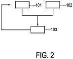
- step 101 an introduction element 4, which is introduced into an object 9, is moved by using a moving unit 2.
- a catheter 4 is moved within the person 9 by using the robotic unit 2 in accordance with an input into the robotic unit 2 provided by a user via the input unit 27.
- tracking images of the introduction element 4 within the object 9 are generated by a tracking image generating unit 3, wherein a radiation beam 7 for traversing the object 9 is emitted by a radiation source 5 of the tracking image generating unit 3 and the radiation beam 7 is detected after having traversed the object 9 by a radiation detector 6 of the tracking image generating unit 3 for generating a tracking image.
- step 103 the radiation beam 7 is controlled by a controller 8, wherein the moving unit 2 provides movement parameters, which define a movement of the introduction element 4 within the object 9, to the tracking image generating unit 3 and wherein the controller 8 controls the radiation beam 7 depending on the provided movement parameters such that the radiation beam 7 traverses a region of the object 9 that includes the introduction element 4.
- step 103 the controller controls the radiation beam 7 also depending on the position of the introduction element 4 within the tracking image generated in step 102.
- Steps 101 to 103 are preferentially performed in a loop, wherein the controller 8 controls the radiation beam 7 such that the introduction element 4, in particular, the tip of the introduction element 4, is centrally located in the tracking images and such that the collimation, i.e. the width, of the radiation beam 7 is determined depending on the movement parameters received from the moving unit 2.
- the procedure in accordance with step 103 can be regarded as defining a controlling method for controlling a radiation beam of a tracking image generating unit of an interventional system, wherein the controlling method comprises controlling the radiation beam depending on movement parameters provided by the moving unit of the interventional system such that the radiation beam traverses a region of an object that includes the introduction element.
- WO 2005/009243 A1 discloses a tight collimation technique that automatically detects relevant regions of interest (ROIs) in technical images and that tries to limit the extent of the x-ray radiation beam as much as possible to only the ROI.
- ROIs regions of interest
- the tight collimation technique uses image analysis algorithms for defining clinically relevant ROIs at any step of the interventional procedure.
- the image analysis algorithms can further be adapted to define safety margins around the clinical relevant ROIs, in order to take into account sudden movements of an interventional instrument like a catheter due to, for example, sudden movements performed by the physician.
- the safety margin would need to be larger than the largest distance the introduction element can travel between consecutive frames, i.e. between consecutive tracking images generated by the tracking image generating unit 3.
- the corresponding region can be relatively large, for instance, it can cover an area being up to five times larger than the area of the clinically relevant ROI. This would lead to a relatively large radiation dose, even if the tight collimation technique is used.
- the interventional system would not know to which location the catheter has been moved and, thus, the interventional system would need to control the collimator such that its shutters are opened completely, in order to reacquire the introduction element upon reassuming the fluoroscopy process, i.e. upon resuming the generation of the several tracking images for tracking the introduction element within the person.
- the interventional system described above with reference to Fig. 1 is therefore adapted to use the movement information from the robotic unit 2 to aid in the tracking of the introduction element with the tight collimation.
- the movement parameters which can define translational information, can be transferred from the robotic unit 2 to the tracking image generating unit 3 via a wired or wireless data connection. Besides the movement parameters, also further information may be transferred from the robotic unit 2 to the tracking image generating unit 3 or to the processing unit 11 like the kind of the catheter moved by the moving unit 2.
- the kind of catheter can be indicative of the actual phase of the interventional procedure performed by the interventional system.
- the transferred movement parameters can include information about the shape and therewith the orientation of the catheter, i.e. the movement parameters can include information about the direction in which the catheter is pointing. This direction is the moving direction, in which the catheter is actually moved.
- the catheter system is preferentially adapted to synchronize the image information provided by the tracking images and the movement parameters, i.e. the movement information, provided by the robotic unit 2. This synchronization is important, in order to allow the controller 8 to know, which image corresponds to which real physical movement defined by the movement parameters or to which real physical position of the catheter, in particular to which real physical position of the tip of the catheter, as defined by the movement parameters.
- the controller 8 uses times assigned to the sequence of real physical positions of the tip of the catheter 4 as defined by the movement parameters received from the robotic unit 2 and times, at which the generated tracking images showing the tip of the catheter 4 during the movement have been acquired, for synchronizing the real physical positions of the tip of the catheter 4 as defined by the movement parameters provided by the robotic unit 2 with the acquisition times of the generated tracking images. In this way it can be known, which sets of data belong to each other.
- the robotic unit 2 can be, for instance, the CorPath 200 from the company Corindus, the Magalan system from the company Hansen Medical or another robotic unit, which can be used for moving an introduction element like a catheter within an object, wherein the respective robotic unit is adapted to provide the movement parameters to the tracking image generating unit 3.
- the robotic unit can be adapted to allow the user, for instance, a physician, to control the introduction element with, for instance, a joystick from behind a lead screen, in order to reduce the radiation dose received by the user.
- the controller 8 can be adapted to convert the movement parameters obtained from the robotic unit 2 from a robot reference frame defined by the robotic unit 2 to an image reference frame defined by the tracking image generating unit 3.
- corresponding transformation rules have to be determined, which relate the robot reference frame to the image reference frame.
- These transformation rules can be defined, for instance, by a calibration procedure, wherein positions and distances in the tracking images, i.e. in the image reference frame, are determined, while the corresponding positions and/or distances in the robot reference frame are known.
- This calibration can be performed pre-procedural, i.e. before the interventional procedure is performed, or during the interventional procedure, wherein in the latter case continuously catheter movements as input by the user into the robotic unit 2, i.e.
- the above described determinations or calculations performed by the controller 8, which are performed for controlling the radiation beam depending on the movement parameters and depending on the identified introduction element identified in the tracking images, can be performed in the reference image frame.
- the input from the robotic unit 2, i.e. the movement parameters, provided to the tracking image generating unit 3 can be used by the controller 8 for controlling the components defining the direction and the collimation of the radiation beam, if the radiation source 5 is switched off.
- This allows, for instance, the collimator, in particular one or several shutters of the collimator, to start moving in the right direction in accordance with the movement defined by the movement parameters, before the radiation source 5 is switched on again for acquiring a tracking image, thereby reducing the response time of the interventional system, which in turn can be used to reduce the safety margin in accordance with, for instance, equation (1).
- the collimator 20 can be a standard collimator, in particular a standard symmetric collimator, as used in current x-ray C-arm systems.
- the collimator can also be a more complex collimator that allows for a more flexible control.
- the collimator may be a multileaf collimator, which may comprise multiple independently positionable leafs.
- the controller is adapted to control the tracking image generating unit such that the tip of the introduction element is centrally located within the tracking images
- the tracking image generating unit can be controlled such that the tip of the introduction element is shown at another position within the tracking images.
- the tracking image generating unit can be controlled such that in front of the tip of the introduction element, i.e. in the direction of the movement of the introduction element in the image reference frame as defined by the transformed movement parameters that have been transformed to the image reference frame, the space within the tracking images is larger than behind the tip of the introduction element, i.e. larger than the space in the opposite direction, because it is more important for a user like a physician to have a visualization of the space, in which the tip of the introduction element is moved, than having a visualization of the space, from which the tip of the introduction element is moved away.
- the tracking image generating unit is an x-ray C-arm system
- the tracking image generating unit can also be another device for generating the tracking images, which comprises a radiation source for generating radiation traversing the object, a radiation detector for detecting the radiation, after it has traversed the object, and a controller for controlling the tracking image generating unit depending on movement parameters received from a moving unit for moving an introduction element within the object.
- the interventional system is a catheter system
- the interventional system can also be another system adapted to perform an interventional procedure, wherein an interventional instrument is introduced into an object as the introduction element.
- an interventional instrument is introduced into an object as the introduction element.
- a needle can be used as the interventional instrument.
- the interventional system can be any interventional x-ray system.
- a single unit or device may fulfill the functions of several items recited in the claims.
- the mere fact that certain measures are recited in mutually different dependent claims does not indicate that a combination of these measures cannot be used to advantage.
- Operations like the control of the radiation beam depending on the provided movement parameters, the determination of the position of the introduction element within the object based on the movement parameters, the determination of an accuracy value being indicative of the accuracy of the determination of the position of the introduction element, the identification of the introduction element in the generated tracking images, et cetera performed by one or several units or devices can be performed by any other number of units or devices.
- These operations and/or the control of the interventional system in accordance with the interventional method and/or the control of the radiation beam by the controller in accordance with the controlling method can be implemented as program code means of a computer program and/or as dedicated hardware.
- a computer program may be stored/distributed on a suitable medium, such as an optical storage medium or a solid-state medium, supplied together with or as part of other hardware, but may also be distributed in other forms, such as via the Internet or other wired or wireless telecommunication systems.
- a suitable medium such as an optical storage medium or a solid-state medium, supplied together with or as part of other hardware, but may also be distributed in other forms, such as via the Internet or other wired or wireless telecommunication systems.
- the invention relates to an interventional system comprising an introduction element like a catheter for being introduced into an object, for instance, a person.
- a moving unit like a robot moves the introduction element within the object, wherein a tracking image generating unit generates tracking images of the introduction element within the object and wherein a controller controls the tracking image generating unit depending on movement parameters of the moving unit, which are indicative of the movement, such that the tracking images show the introduction element.
- This control can be performed very accurately based on the known real physical movement of the introduction element such that it is not necessary to, for instance, irradiate a relatively large area of the object for ensuring that the introduction element is really captured by the tracking images, thereby allowing for a reduced radiation dose applied to the object.
Landscapes
- Health & Medical Sciences (AREA)
- Life Sciences & Earth Sciences (AREA)
- Engineering & Computer Science (AREA)
- Medical Informatics (AREA)
- Surgery (AREA)
- Nuclear Medicine, Radiotherapy & Molecular Imaging (AREA)
- Molecular Biology (AREA)
- Animal Behavior & Ethology (AREA)
- Veterinary Medicine (AREA)
- Biomedical Technology (AREA)
- Heart & Thoracic Surgery (AREA)
- Public Health (AREA)
- General Health & Medical Sciences (AREA)
- Radiology & Medical Imaging (AREA)
- Pathology (AREA)
- Physics & Mathematics (AREA)
- Biophysics (AREA)
- High Energy & Nuclear Physics (AREA)
- Optics & Photonics (AREA)
- Robotics (AREA)
- Gynecology & Obstetrics (AREA)
- Oral & Maxillofacial Surgery (AREA)
- Apparatus For Radiation Diagnosis (AREA)
- Radiation-Therapy Devices (AREA)
Claims (13)
- Interventionssystem, umfassend:- ein Einführungselement (4) zum Einführen in ein Objekt (9),- eine Bewegungseinheit (2) zum Bewegen des Einführungselements (4) innerhalb des Objekts (9),- eine Verfolgungsbilderzeugungseinheit (3) zum Erzeugen von Verfolgungsbildern des Einführungselements (4) innerhalb des Objekts (9), wobei die Verfolgungsbilderzeugungseinheit (3) eine Strahlungsquelle (5) zum Emittieren eines Strahlenbündels (7) zum Durchqueren des Objekts (9), einen Strahlungsdetektor (6) zum Detektieren des Strahlenbündels (7), nachdem es das Objekt (9) durchquert hat, und eine Steuereinheit (8) zum Steuern der Verfolgungsbilderzeugungseinheit (3) umfasst, wobei die Bewegungseinheit (2) dafür ausgelegt ist, Bewegungsparameter, die eine Bewegung des Einführungselements (4) innerhalb des Objekts (9) definieren, über eine verdrahtete oder drahtlose Datenverbindung für die Verfolgungsbilderzeugungseinheit (3) bereitzustellen, und wobei die Steuereinheit (8) dafür ausgelegt ist, die Verfolgungsbilderzeugungseinheit (3) in Abhängigkeit von den bereitgestellten Bewegungsparametern derartig zu steuern, dass das Strahlenbündel (7) eine Region des Objekts (9) durchquert, die das Einführungselement (4) enthält.
- Interventionssystem nach Anspruch 1, wobei die Verfolgungsbilderzeugungseinheit (3) einen Kollimator (20) zum Kollimieren des Strahlenbündels (7) umfasst und wobei die Steuereinheit (8) dafür ausgelegt ist, den Kollimator (20) derartig zu steuern, dass das Strahlenbündel (7) in Abhängigkeit von den bereitgestellten Bewegungsparametern derartig kollimiert wird, dass das Strahlenbündel (7) eine Region des Objekts (9) durchquert, die das Einführungselement (4) enthält.
- Interventionssystem nach Anspruch 2, wobei die Steuereinheit (8) dafür ausgelegt ist, den Kollimator (20) in Abhängigkeit von einer Bewegungsgeschwindigkeit wie durch die Bewegungsparameter definiert und/oder einer Reaktionszeit des Interventionssystems (1) zu steuern.
- Interventionssystem nach Anspruch 3, wobei die Steuereinheit (8) dafür ausgelegt ist, den Kollimator (20) in Abhängigkeit von der Bewegungsgeschwindigkeit wie durch die Bewegungsparameter definiert und/oder der Reaktionszeit des Interventionssystems (1) derartig zu steuern, dass ein Teil des Strahlenbündels (7), das sich in Bezug auf eine durch die Bewegungsparameter definierte Bewegungsrichtung vor dem Einführungselement (4) befindet, mit zunehmender Geschwindigkeit und/oder mit zunehmender Reaktionszeit zunimmt.
- Interventionssystem nach Anspruch 2, wobei das Interventionssystem (1) weiterhin eine Positionsbestimmungseinheit (22) zum Bestimmen der Position des Einführungselements (4) innerhalb des Objekts (9) basierend auf den Bewegungsparametern umfasst, wobei die Steuereinheit (8) dafür ausgelegt ist, die Verfolgungsbilderzeugungseinheit (3) in Abhängigkeit von der bestimmten Position des Einführungselements (4) zu steuern.
- Interventionssystem nach Anspruch 5, wobei die Verfolgungsbilderzeugungseinheit (3) einen Kollimator (20) zum Kollimieren des Strahlenbündels (7) umfasst, wobei die Positionsbestimmungseinheit (22) dafür ausgelegt ist, zusätzlich einen Genauigkeitswert zu bestimmen, der die Genauigkeit der Positionsbestimmung angibt, und wobei die Steuereinheit (8) dafür ausgelegt ist, den Kollimator (20) in Abhängigkeit von dem Genauigkeitswert zu steuern.
- Interventionssystem nach Anspruch 6, wobei die Steuereinheit (8) dafür ausgelegt ist, den Kollimator (20) derartig zu steuern, dass der Kollimator (20) eine schmalere Öffnung hat, wenn der Genauigkeitswert eine höhere Genauigkeit angibt, und dass der Kollimator (20) eine breitere Öffnung hat, wenn der Genauigkeitswert eine niedrigere Genauigkeit angibt.
- Interventionssystem nach Anspruch 1, wobei das Interventionssystem (1) weiterhin eine Identifizierungseinheit (23) zum Identifizieren des Einführungselements (4) in den erzeugten Verfolgungsbildern umfasst, wobei die Steuereinheit (8) dafür ausgelegt ist, die Verfolgungsbilderzeugungseinheit (3) in Abhängigkeit von der Identifizierung des Einführungselements (4) in den erzeugten Verfolgungsbildern zu steuern.
- Interventionssystem nach Anspruch 1, wobei das Interventionssystem (1) weiterhin umfasst:- eine Positionsbestimmungseinheit (22) zum Bestimmen der Position des Einführungselements (4) innerhalb des Objekts (9) basierend auf den Bewegungsparametern,- eine Objektbildbereitstellungseinheit (24) zum Bereitstellen eines Objektbilds, das das Objekt (9) zeigt,- eine Anzeige (27) zum Anzeigen des Objektbilds und einer Darstellung des Einführungselements (4) an der bestimmten Position des Einführungselements (4) in dem Objektbild.
- Interventionssystem nach Anspruch 1, wobei das Interventionssystem (1) weiterhin umfasst:- eine Objektbildbereitstellungseinheit zum Bereitstellen eines Objektbilds, das das Objekt (9) zeigt,- eine Überlagerungsbildbestimmungseinheit (25) zum Bestimmen eines Überlagerungsbilds, das eine Überlagerung des Objektbilds und des Zielbilds ist,- eine Anzeige (27) zum Anzeigen des Objektbilds und des Verfolgungsbilds in einer einander überlagerter Weise.
- Steuerungsverfahren zum Steuern einer Verfolgungsbilderzeugungseinheit eines Interventionssystems nach Anspruch 1, wobei das Steuerungsverfahren das Empfangen von Bewegungsparametern, die eine Bewegung eines Einführungselements (4) innerhalb eines Objekts (9) definieren, von einer Bewegungseinheit (2) des Interventionssystems (1) über eine verdrahtete oder drahtlose Datenverbindung umfasst und das Steuern der Verfolgungsbilderzeugungseinheit (3) in Abhängigkeit von den durch die Bewegungseinheit (2) bereitgestellten Bewegungsparametern auf derartige Weise umfasst, dass das Strahlenbündel (7) eine Region des Objekts (9) durchquert, die das Einführungselement (4) enthält.
- Interventionelles Computerprogramm umfassend Programmcodemittel zum Veranlassen eines Interventionssystems (1) nach Anspruch 1, die folgenden Schritte durchzuführen, wenn das interventionelle Computerprogramm auf einem Computer ausgeführt wird, der das Interventionssystem (1) steuert:- Bewegen eines Einführungselements (4) innerhalb eines Objekts (9) durch eine Bewegungseinheit (2),- Erzeugen von Verfolgungsbildern des Einführungselements (4) innerhalb des Objekts (9) durch eine Verfolgungsbilderzeugungseinheit (3), wobei ein Strahlenbündel (7) zum Durchqueren des Objekts (9) durch eine Strahlungsquelle (5) der Verfolgungsbilderzeugungseinheit (3) emittiert wird und das Strahlenbündel (7) durch einen Strahlungsdetektor (6) der Verfolgungsbilderzeugungseinheit (3) detektiert wird, nachdem es das Objekt (9) durchquert hat,wobei die Bewegungseinheit (2) Bewegungsparameter, die eine Bewegung des Einführungselements (4) innerhalb des Objekts (9) definieren, über eine verdrahtete oder drahtlose Datenverbindung für die Verfolgungsbilderzeugungseinheit (3) bereitstellt, und wobei eine Steuereinheit (8) die Verfolgungsbilderzeugungseinheit (3) in Abhängigkeit von den bereitgestellten Bewegungsparametern derartig steuert, dass das Strahlenbündel (7) eine Region des Objekts (9) durchquert, die das Einführungselement (4) enthält.
- Steuerungscomputerprogramm zum Steuern einer Verfolgungsbilderzeugungseinheit eines Interventionssystems nach Anspruch 1, wobei das Steuerungscomputerprogramm Programmcodemittel zum Veranlassen der Steuereinheit (8) der Verfolgungsbilderzeugungseinheit umfasst, die Schritte des Steuerungsverfahrens nach Anspruch 11 durchzuführen, wenn das Steuerungscomputerprogramm auf der Steuereinheit (8) ausgeführt wird.
Applications Claiming Priority (2)
| Application Number | Priority Date | Filing Date | Title |
|---|---|---|---|
| US201261736637P | 2012-12-13 | 2012-12-13 | |
| PCT/IB2013/060701 WO2014091380A1 (en) | 2012-12-13 | 2013-12-06 | Interventional system |
Publications (2)
| Publication Number | Publication Date |
|---|---|
| EP2931127A1 EP2931127A1 (de) | 2015-10-21 |
| EP2931127B1 true EP2931127B1 (de) | 2018-02-21 |
Family
ID=49943430
Family Applications (1)
| Application Number | Title | Priority Date | Filing Date |
|---|---|---|---|
| EP13818811.5A Active EP2931127B1 (de) | 2012-12-13 | 2013-12-06 | Interventionssystem |
Country Status (6)
| Country | Link |
|---|---|
| US (2) | US11576644B2 (de) |
| EP (1) | EP2931127B1 (de) |
| JP (1) | JP6388596B2 (de) |
| CN (1) | CN104869904B (de) |
| RU (1) | RU2656512C2 (de) |
| WO (1) | WO2014091380A1 (de) |
Cited By (1)
| Publication number | Priority date | Publication date | Assignee | Title |
|---|---|---|---|---|
| US11918309B2 (en) | 2020-04-09 | 2024-03-05 | Siemens Healthcare Gmbh | Imaging a robotically moved medical object |
Families Citing this family (4)
| Publication number | Priority date | Publication date | Assignee | Title |
|---|---|---|---|---|
| CN104853680B (zh) * | 2012-12-11 | 2018-04-10 | 皇家飞利浦有限公司 | 用于确定对象内的目标元件的空间维度的空间维度确定设备 |
| EP3658032A4 (de) * | 2017-07-26 | 2021-03-03 | Shenzhen Xpectvision Technology Co., Ltd. | Röntgenbildgebungssystem und verfahren zur röntgenbildverfolgung |
| EP3461416A1 (de) * | 2017-09-28 | 2019-04-03 | Koninklijke Philips N.V. | Führen eines intravaskulären us-katheters |
| DE102020204985A1 (de) | 2020-04-21 | 2021-10-21 | Siemens Healthcare Gmbh | Steuerung eines robotisch bewegten medizinischen Objekts |
Citations (1)
| Publication number | Priority date | Publication date | Assignee | Title |
|---|---|---|---|---|
| US20060247520A1 (en) * | 2005-04-28 | 2006-11-02 | Boston Scientific Scimed, Inc. | Automated manipulation of imaging device field of view based on tracked medical device position |
Family Cites Families (20)
| Publication number | Priority date | Publication date | Assignee | Title |
|---|---|---|---|---|
| RU2166909C1 (ru) * | 2000-05-18 | 2001-05-20 | Восканян Юрий Эдуардович | Способ визуализации артерий нижних конечностей методом магнитно-резонансной ангиографии |
| US20090182226A1 (en) | 2001-02-15 | 2009-07-16 | Barry Weitzner | Catheter tracking system |
| CA2348135A1 (en) | 2001-05-17 | 2002-11-17 | Cedara Software Corp. | 3-d navigation for x-ray imaging system |
| US7894877B2 (en) * | 2002-05-17 | 2011-02-22 | Case Western Reserve University | System and method for adjusting image parameters based on device tracking |
| RU2252692C2 (ru) * | 2003-07-25 | 2005-05-27 | ОБЩЕСТВО С ОГРАНИЧЕННОЙ ОТВЕТСТВЕННОСТЬЮ НАУЧНО-ПРОИЗВОДСТВЕННО-КОНСТРУКТОРСКАЯ ФИРМА "Медиком МТД" | Способ исследования функционального состояния головного мозга, устройство для исследования функционального состояния головного мозга и способ измерения подэлектродного сопротивления |
| EP1651112B1 (de) | 2003-07-30 | 2010-10-27 | Philips Intellectual Property & Standards GmbH | Röntgeneinrichtung mit automatisch einstellbarem kollimator |
| US10555775B2 (en) * | 2005-05-16 | 2020-02-11 | Intuitive Surgical Operations, Inc. | Methods and system for performing 3-D tool tracking by fusion of sensor and/or camera derived data during minimally invasive robotic surgery |
| US8073528B2 (en) * | 2007-09-30 | 2011-12-06 | Intuitive Surgical Operations, Inc. | Tool tracking systems, methods and computer products for image guided surgery |
| JP4738270B2 (ja) * | 2006-07-14 | 2011-08-03 | 株式会社日立メディコ | 手術支援装置 |
| US20080119725A1 (en) * | 2006-11-20 | 2008-05-22 | General Electric Company | Systems and Methods for Visual Verification of CT Registration and Feedback |
| DE102007059599B4 (de) * | 2007-12-11 | 2017-06-22 | Siemens Healthcare Gmbh | Vorrichtung für eine medizinische Intervention und Betriebsverfahren für eine Vorrichtung für eine medizinische Intervention |
| RU2010130474A (ru) * | 2007-12-21 | 2012-01-27 | Конинклейке Филипс Электроникс, Н.В. (Nl) | Синхронный интервенционный сканер |
| US8792964B2 (en) * | 2008-03-12 | 2014-07-29 | Siemens Aktiengesellschaft | Method and apparatus for conducting an interventional procedure involving heart valves using a robot-based X-ray device |
| JP2010051572A (ja) * | 2008-08-28 | 2010-03-11 | Fujifilm Corp | 放射線画像撮影システム |
| DE102008062032B4 (de) | 2008-12-12 | 2010-09-23 | Siemens Aktiengesellschaft | Medizinischer Arbeitsplatz und Verfahren zu dessen Betreiben |
| US7983391B2 (en) * | 2009-04-27 | 2011-07-19 | Machan Lindsay S | System for reduction of exposure to X-ray radiation |
| CN101803952A (zh) | 2010-03-05 | 2010-08-18 | 南开大学 | Ct图像导航脊柱微创手术机器人运动控制系统 |
| US9833293B2 (en) * | 2010-09-17 | 2017-12-05 | Corindus, Inc. | Robotic catheter system |
| US9439606B2 (en) * | 2010-12-09 | 2016-09-13 | Koninklijke Philips N.V. | Interventional apparatus activated computed tomography (CT) |
| EP2685900B1 (de) | 2011-03-15 | 2022-12-21 | Koninklijke Philips N.V. | Medizinische bildgebungsvorrichtung zur bereitstellung einer bilddarstellung zur unterstützung bei der positionierung einer eingriffsvorrichtung |
-
2013
- 2013-12-06 EP EP13818811.5A patent/EP2931127B1/de active Active
- 2013-12-06 WO PCT/IB2013/060701 patent/WO2014091380A1/en active Application Filing
- 2013-12-06 RU RU2015127997A patent/RU2656512C2/ru active
- 2013-12-06 US US14/648,382 patent/US11576644B2/en active Active
- 2013-12-06 CN CN201380065078.5A patent/CN104869904B/zh active Active
- 2013-12-06 JP JP2015547224A patent/JP6388596B2/ja active Active
-
2023
- 2023-01-09 US US18/094,450 patent/US12089981B2/en active Active
Patent Citations (1)
| Publication number | Priority date | Publication date | Assignee | Title |
|---|---|---|---|---|
| US20060247520A1 (en) * | 2005-04-28 | 2006-11-02 | Boston Scientific Scimed, Inc. | Automated manipulation of imaging device field of view based on tracked medical device position |
Cited By (1)
| Publication number | Priority date | Publication date | Assignee | Title |
|---|---|---|---|---|
| US11918309B2 (en) | 2020-04-09 | 2024-03-05 | Siemens Healthcare Gmbh | Imaging a robotically moved medical object |
Also Published As
| Publication number | Publication date |
|---|---|
| JP2015536790A (ja) | 2015-12-24 |
| WO2014091380A1 (en) | 2014-06-19 |
| US12089981B2 (en) | 2024-09-17 |
| CN104869904B (zh) | 2018-08-17 |
| US20150342556A1 (en) | 2015-12-03 |
| RU2656512C2 (ru) | 2018-06-05 |
| JP6388596B2 (ja) | 2018-09-12 |
| RU2015127997A (ru) | 2017-01-18 |
| US20230148987A1 (en) | 2023-05-18 |
| CN104869904A (zh) | 2015-08-26 |
| US11576644B2 (en) | 2023-02-14 |
| EP2931127A1 (de) | 2015-10-21 |
Similar Documents
| Publication | Publication Date | Title |
|---|---|---|
| EP2991555B1 (de) | Interventionelles röntgensystem | |
| US12089981B2 (en) | Interventional system | |
| CN109567954B (zh) | 图像引导程序的工作流程辅助系统及方法 | |
| EP2685900B1 (de) | Medizinische bildgebungsvorrichtung zur bereitstellung einer bilddarstellung zur unterstützung bei der positionierung einer eingriffsvorrichtung | |
| RU2687826C2 (ru) | Устройство оказания помощи пользователю во время хирургической процедуры | |
| AU2015238800B2 (en) | Real-time simulation of fluoroscopic images | |
| CN113164137B (zh) | 对医学x射线成像装置进行定位 | |
| EP2984987A1 (de) | Markierung des fluoroskopsichtfelds | |
| US8467850B2 (en) | System and method to determine the position of a medical instrument | |
| JP2022147619A (ja) | 画像表示装置及び画像表示プログラム | |
| WO2014155280A1 (en) | Interventionist hand radiation protection |
Legal Events
| Date | Code | Title | Description |
|---|---|---|---|
| PUAI | Public reference made under article 153(3) epc to a published international application that has entered the european phase |
Free format text: ORIGINAL CODE: 0009012 |
|
| 17P | Request for examination filed |
Effective date: 20150713 |
|
| AK | Designated contracting states |
Kind code of ref document: A1 Designated state(s): AL AT BE BG CH CY CZ DE DK EE ES FI FR GB GR HR HU IE IS IT LI LT LU LV MC MK MT NL NO PL PT RO RS SE SI SK SM TR |
|
| AX | Request for extension of the european patent |
Extension state: BA ME |
|
| DAX | Request for extension of the european patent (deleted) | ||
| 17Q | First examination report despatched |
Effective date: 20160316 |
|
| GRAP | Despatch of communication of intention to grant a patent |
Free format text: ORIGINAL CODE: EPIDOSNIGR1 |
|
| RIC1 | Information provided on ipc code assigned before grant |
Ipc: A61B 6/12 20060101ALI20170616BHEP Ipc: A61B 6/00 20060101AFI20170616BHEP Ipc: A61B 6/06 20060101ALI20170616BHEP Ipc: A61B 90/00 20160101ALI20170616BHEP |
|
| INTG | Intention to grant announced |
Effective date: 20170707 |
|
| GRAS | Grant fee paid |
Free format text: ORIGINAL CODE: EPIDOSNIGR3 |
|
| GRAA | (expected) grant |
Free format text: ORIGINAL CODE: 0009210 |
|
| AK | Designated contracting states |
Kind code of ref document: B1 Designated state(s): AL AT BE BG CH CY CZ DE DK EE ES FI FR GB GR HR HU IE IS IT LI LT LU LV MC MK MT NL NO PL PT RO RS SE SI SK SM TR |
|
| REG | Reference to a national code |
Ref country code: GB Ref legal event code: FG4D |
|
| REG | Reference to a national code |
Ref country code: CH Ref legal event code: EP |
|
| REG | Reference to a national code |
Ref country code: DE Ref legal event code: R096 Ref document number: 602013033456 Country of ref document: DE Ref country code: AT Ref legal event code: REF Ref document number: 970814 Country of ref document: AT Kind code of ref document: T Effective date: 20180315 |
|
| REG | Reference to a national code |
Ref country code: IE Ref legal event code: FG4D |
|
| REG | Reference to a national code |
Ref country code: NL Ref legal event code: MP Effective date: 20180221 |
|
| REG | Reference to a national code |
Ref country code: LT Ref legal event code: MG4D |
|
| REG | Reference to a national code |
Ref country code: AT Ref legal event code: MK05 Ref document number: 970814 Country of ref document: AT Kind code of ref document: T Effective date: 20180221 |
|
| PG25 | Lapsed in a contracting state [announced via postgrant information from national office to epo] |
Ref country code: ES Free format text: LAPSE BECAUSE OF FAILURE TO SUBMIT A TRANSLATION OF THE DESCRIPTION OR TO PAY THE FEE WITHIN THE PRESCRIBED TIME-LIMIT Effective date: 20180221 Ref country code: NL Free format text: LAPSE BECAUSE OF FAILURE TO SUBMIT A TRANSLATION OF THE DESCRIPTION OR TO PAY THE FEE WITHIN THE PRESCRIBED TIME-LIMIT Effective date: 20180221 Ref country code: HR Free format text: LAPSE BECAUSE OF FAILURE TO SUBMIT A TRANSLATION OF THE DESCRIPTION OR TO PAY THE FEE WITHIN THE PRESCRIBED TIME-LIMIT Effective date: 20180221 Ref country code: LT Free format text: LAPSE BECAUSE OF FAILURE TO SUBMIT A TRANSLATION OF THE DESCRIPTION OR TO PAY THE FEE WITHIN THE PRESCRIBED TIME-LIMIT Effective date: 20180221 Ref country code: NO Free format text: LAPSE BECAUSE OF FAILURE TO SUBMIT A TRANSLATION OF THE DESCRIPTION OR TO PAY THE FEE WITHIN THE PRESCRIBED TIME-LIMIT Effective date: 20180521 Ref country code: FI Free format text: LAPSE BECAUSE OF FAILURE TO SUBMIT A TRANSLATION OF THE DESCRIPTION OR TO PAY THE FEE WITHIN THE PRESCRIBED TIME-LIMIT Effective date: 20180221 Ref country code: CY Free format text: LAPSE BECAUSE OF FAILURE TO SUBMIT A TRANSLATION OF THE DESCRIPTION OR TO PAY THE FEE WITHIN THE PRESCRIBED TIME-LIMIT Effective date: 20180221 |
|
| PG25 | Lapsed in a contracting state [announced via postgrant information from national office to epo] |
Ref country code: LV Free format text: LAPSE BECAUSE OF FAILURE TO SUBMIT A TRANSLATION OF THE DESCRIPTION OR TO PAY THE FEE WITHIN THE PRESCRIBED TIME-LIMIT Effective date: 20180221 Ref country code: SE Free format text: LAPSE BECAUSE OF FAILURE TO SUBMIT A TRANSLATION OF THE DESCRIPTION OR TO PAY THE FEE WITHIN THE PRESCRIBED TIME-LIMIT Effective date: 20180221 Ref country code: GR Free format text: LAPSE BECAUSE OF FAILURE TO SUBMIT A TRANSLATION OF THE DESCRIPTION OR TO PAY THE FEE WITHIN THE PRESCRIBED TIME-LIMIT Effective date: 20180522 Ref country code: AT Free format text: LAPSE BECAUSE OF FAILURE TO SUBMIT A TRANSLATION OF THE DESCRIPTION OR TO PAY THE FEE WITHIN THE PRESCRIBED TIME-LIMIT Effective date: 20180221 Ref country code: RS Free format text: LAPSE BECAUSE OF FAILURE TO SUBMIT A TRANSLATION OF THE DESCRIPTION OR TO PAY THE FEE WITHIN THE PRESCRIBED TIME-LIMIT Effective date: 20180221 Ref country code: BG Free format text: LAPSE BECAUSE OF FAILURE TO SUBMIT A TRANSLATION OF THE DESCRIPTION OR TO PAY THE FEE WITHIN THE PRESCRIBED TIME-LIMIT Effective date: 20180521 |
|
| PG25 | Lapsed in a contracting state [announced via postgrant information from national office to epo] |
Ref country code: IT Free format text: LAPSE BECAUSE OF FAILURE TO SUBMIT A TRANSLATION OF THE DESCRIPTION OR TO PAY THE FEE WITHIN THE PRESCRIBED TIME-LIMIT Effective date: 20180221 Ref country code: AL Free format text: LAPSE BECAUSE OF FAILURE TO SUBMIT A TRANSLATION OF THE DESCRIPTION OR TO PAY THE FEE WITHIN THE PRESCRIBED TIME-LIMIT Effective date: 20180221 Ref country code: EE Free format text: LAPSE BECAUSE OF FAILURE TO SUBMIT A TRANSLATION OF THE DESCRIPTION OR TO PAY THE FEE WITHIN THE PRESCRIBED TIME-LIMIT Effective date: 20180221 Ref country code: PL Free format text: LAPSE BECAUSE OF FAILURE TO SUBMIT A TRANSLATION OF THE DESCRIPTION OR TO PAY THE FEE WITHIN THE PRESCRIBED TIME-LIMIT Effective date: 20180221 Ref country code: RO Free format text: LAPSE BECAUSE OF FAILURE TO SUBMIT A TRANSLATION OF THE DESCRIPTION OR TO PAY THE FEE WITHIN THE PRESCRIBED TIME-LIMIT Effective date: 20180221 |
|
| REG | Reference to a national code |
Ref country code: DE Ref legal event code: R097 Ref document number: 602013033456 Country of ref document: DE |
|
| PG25 | Lapsed in a contracting state [announced via postgrant information from national office to epo] |
Ref country code: DK Free format text: LAPSE BECAUSE OF FAILURE TO SUBMIT A TRANSLATION OF THE DESCRIPTION OR TO PAY THE FEE WITHIN THE PRESCRIBED TIME-LIMIT Effective date: 20180221 Ref country code: SM Free format text: LAPSE BECAUSE OF FAILURE TO SUBMIT A TRANSLATION OF THE DESCRIPTION OR TO PAY THE FEE WITHIN THE PRESCRIBED TIME-LIMIT Effective date: 20180221 Ref country code: CZ Free format text: LAPSE BECAUSE OF FAILURE TO SUBMIT A TRANSLATION OF THE DESCRIPTION OR TO PAY THE FEE WITHIN THE PRESCRIBED TIME-LIMIT Effective date: 20180221 Ref country code: SK Free format text: LAPSE BECAUSE OF FAILURE TO SUBMIT A TRANSLATION OF THE DESCRIPTION OR TO PAY THE FEE WITHIN THE PRESCRIBED TIME-LIMIT Effective date: 20180221 |
|
| PLBE | No opposition filed within time limit |
Free format text: ORIGINAL CODE: 0009261 |
|
| STAA | Information on the status of an ep patent application or granted ep patent |
Free format text: STATUS: NO OPPOSITION FILED WITHIN TIME LIMIT |
|
| 26N | No opposition filed |
Effective date: 20181122 |
|
| PG25 | Lapsed in a contracting state [announced via postgrant information from national office to epo] |
Ref country code: SI Free format text: LAPSE BECAUSE OF FAILURE TO SUBMIT A TRANSLATION OF THE DESCRIPTION OR TO PAY THE FEE WITHIN THE PRESCRIBED TIME-LIMIT Effective date: 20180221 |
|
| REG | Reference to a national code |
Ref country code: CH Ref legal event code: PL |
|
| PG25 | Lapsed in a contracting state [announced via postgrant information from national office to epo] |
Ref country code: LU Free format text: LAPSE BECAUSE OF NON-PAYMENT OF DUE FEES Effective date: 20181206 Ref country code: MC Free format text: LAPSE BECAUSE OF FAILURE TO SUBMIT A TRANSLATION OF THE DESCRIPTION OR TO PAY THE FEE WITHIN THE PRESCRIBED TIME-LIMIT Effective date: 20180221 |
|
| REG | Reference to a national code |
Ref country code: IE Ref legal event code: MM4A |
|
| REG | Reference to a national code |
Ref country code: BE Ref legal event code: MM Effective date: 20181231 |
|
| PG25 | Lapsed in a contracting state [announced via postgrant information from national office to epo] |
Ref country code: IE Free format text: LAPSE BECAUSE OF NON-PAYMENT OF DUE FEES Effective date: 20181206 |
|
| PG25 | Lapsed in a contracting state [announced via postgrant information from national office to epo] |
Ref country code: BE Free format text: LAPSE BECAUSE OF NON-PAYMENT OF DUE FEES Effective date: 20181231 |
|
| PG25 | Lapsed in a contracting state [announced via postgrant information from national office to epo] |
Ref country code: CH Free format text: LAPSE BECAUSE OF NON-PAYMENT OF DUE FEES Effective date: 20181231 Ref country code: LI Free format text: LAPSE BECAUSE OF NON-PAYMENT OF DUE FEES Effective date: 20181231 |
|
| PG25 | Lapsed in a contracting state [announced via postgrant information from national office to epo] |
Ref country code: MT Free format text: LAPSE BECAUSE OF NON-PAYMENT OF DUE FEES Effective date: 20181206 |
|
| PG25 | Lapsed in a contracting state [announced via postgrant information from national office to epo] |
Ref country code: TR Free format text: LAPSE BECAUSE OF FAILURE TO SUBMIT A TRANSLATION OF THE DESCRIPTION OR TO PAY THE FEE WITHIN THE PRESCRIBED TIME-LIMIT Effective date: 20180221 |
|
| PG25 | Lapsed in a contracting state [announced via postgrant information from national office to epo] |
Ref country code: PT Free format text: LAPSE BECAUSE OF FAILURE TO SUBMIT A TRANSLATION OF THE DESCRIPTION OR TO PAY THE FEE WITHIN THE PRESCRIBED TIME-LIMIT Effective date: 20180221 |
|
| PG25 | Lapsed in a contracting state [announced via postgrant information from national office to epo] |
Ref country code: HU Free format text: LAPSE BECAUSE OF FAILURE TO SUBMIT A TRANSLATION OF THE DESCRIPTION OR TO PAY THE FEE WITHIN THE PRESCRIBED TIME-LIMIT; INVALID AB INITIO Effective date: 20131206 Ref country code: MK Free format text: LAPSE BECAUSE OF NON-PAYMENT OF DUE FEES Effective date: 20180221 |
|
| PG25 | Lapsed in a contracting state [announced via postgrant information from national office to epo] |
Ref country code: IS Free format text: LAPSE BECAUSE OF FAILURE TO SUBMIT A TRANSLATION OF THE DESCRIPTION OR TO PAY THE FEE WITHIN THE PRESCRIBED TIME-LIMIT Effective date: 20180621 |
|
| PGFP | Annual fee paid to national office [announced via postgrant information from national office to epo] |
Ref country code: GB Payment date: 20231219 Year of fee payment: 11 |
|
| PGFP | Annual fee paid to national office [announced via postgrant information from national office to epo] |
Ref country code: FR Payment date: 20231226 Year of fee payment: 11 |
|
| PGFP | Annual fee paid to national office [announced via postgrant information from national office to epo] |
Ref country code: DE Payment date: 20231227 Year of fee payment: 11 |