EP2931022B1 - Streusystem für eine landwirtschaftliche erntemaschine - Google Patents
Streusystem für eine landwirtschaftliche erntemaschine Download PDFInfo
- Publication number
- EP2931022B1 EP2931022B1 EP13812418.5A EP13812418A EP2931022B1 EP 2931022 B1 EP2931022 B1 EP 2931022B1 EP 13812418 A EP13812418 A EP 13812418A EP 2931022 B1 EP2931022 B1 EP 2931022B1
- Authority
- EP
- European Patent Office
- Prior art keywords
- spreader
- hood
- agricultural material
- agricultural
- hoods
- Prior art date
- Legal status (The legal status is an assumption and is not a legal conclusion. Google has not performed a legal analysis and makes no representation as to the accuracy of the status listed.)
- Active
Links
Images



Classifications
-
- A—HUMAN NECESSITIES
- A01—AGRICULTURE; FORESTRY; ANIMAL HUSBANDRY; HUNTING; TRAPPING; FISHING
- A01F—PROCESSING OF HARVESTED PRODUCE; HAY OR STRAW PRESSES; DEVICES FOR STORING AGRICULTURAL OR HORTICULTURAL PRODUCE
- A01F12/00—Parts or details of threshing apparatus
- A01F12/30—Straw separators, i.e. straw walkers, for separating residual grain from the straw
-
- A—HUMAN NECESSITIES
- A01—AGRICULTURE; FORESTRY; ANIMAL HUSBANDRY; HUNTING; TRAPPING; FISHING
- A01D—HARVESTING; MOWING
- A01D41/00—Combines, i.e. harvesters or mowers combined with threshing devices
- A01D41/12—Details of combines
- A01D41/1243—Devices for laying-out or distributing the straw
Definitions
- the invention relates generally to agricultural equipment, such as harvesters, and more specifically, to a system for spreading agricultural material from a harvester.
- a harvester may be used to harvest agricultural crops, such as barley, beans, corn, cotton, flax, oats, rye, soybeans, wheat, or other plant crops.
- a combine e.g., combine harvester
- a combine is a specific type of harvester generally used to harvest grains (e.g., barley, corn, flax, oats, rye, soybeans, wheat, etc.).
- a combine may be used to separate a plant into different agricultural materials, such as grain, chaff, and straw.
- the combine begins the harvesting process by cutting the plant stalk, usually using a cutting device (i.e., a header).
- the combine then moves the plant from the cutting device into the combine with a feeder system.
- the plant undergoes processes that separate it into agricultural materials.
- Some of these agricultural materials e.g., straw, chaff
- the combine may spread the agricultural material throughout the field for decomposition, and/or may create narrow rows of agricultural material (i.e., create a windrow) for collection by another machine (e.g., a baler).
- a baler e.g., a baler
- current combines may not effectively spread and/or windrow agricultural materials.
- the United States patent application published as US 2010/291984 A1 discloses a crop residue chopping-and-distributing arrangement for a combine harvester.
- the arrangement comprises a straw chopper and two distribution blowers arranged laterally along-side one another.
- a respective first shield On the periphery of the distribution blowers is provided a respective first shield, adjustable about axis of rotation for modifying the distribution characteristics, that can be brought into an active position.
- the first shields are respectively mounted on a rotary holder rotatable about axis of rotation of the associated distribution blower and additionally carry a second shield, which has a smaller dimension in the circumferential direction than first shield, so that second shield can selectively be brought into an active position instead of the first shield.
- a spreader system for an agricultural harvester is provided as defined in claims 1-13.
- FIG. 1 is a rear perspective view of an embodiment of a harvester 10 with a spreader system 12.
- the harvester 10 may harvest grains such as barley, corn, flax, oats, rye, soybeans, wheat, and so forth. Accordingly, the harvester 10 is configured to remove the desired portion of the plant and to separate the portion into different agricultural materials (e.g., grain, straw, and chaff). As discussed above, the harvester discharges this material after processing it. Some of the agricultural materials may exit the rear of the harvester into the spreader system 12.
- the spreader system 12 may direct chaff into spreader discs, to distribute the chaff throughout the field while creating narrow rows of straw 14 behind the harvester 10 (i.e., windrows).
- the spreader system 12 may direct straw and chaff into the spreader discs to distribute the straw and chaff evenly over a field.
- the harvesting process begins with the harvester 10 using a cutting assembly to cut plant stalks.
- An operator of the harvester 10 may be seated in a cab, and may monitor the operation of the cutting assembly and other systems of the harvester 10.
- the harvester 10 moves the plants from the cutting assembly into the harvester 10 for processing.
- the plants may undergo various processes that separate the plant into different agricultural materials (e.g., grain, chaff, straw), generally into two streams of material.
- the first stream of agricultural material (straw and chaff) may then exit the harvester 10 into the spreader system 12.
- the second stream of grain and chaff is winnowed by a fan that separates the chaff from the grain.
- the grain then falls into a cross auger and is elevated to a storage tank to be off-loaded when the operator may choose, via an unloading system.
- the winnowed chaff is blown to the spreader system 12 as a second stream to be spread onto a field.
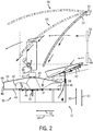
- FIG. 2 is a side view of an embodiment of a spreader system with a hood assembly 30.
- the hood assembly 30 enables the spreader system 12 to effectively spread a first agricultural material (e.g., chaff) and windrow a second agricultural material (e.g., straw) by controlling an upward and rearward airflow (e.g., in direction 32 and 62).
- the spreader system 12 includes the hood assembly 30, a door 34, a first shaft 35, a first hub 36, a frame 38, a chute 40, a spreader disc 42, and an actuator 43.
- the harvester 10 separates plants into different agricultural materials (e.g., grain, straw, and chaff).
- the chaff may be spread onto the field, while the straw is deposited in narrow rows (i.e., windrows) behind the harvester for later collection by another machine (e.g., a baler). In other circumstances, both the chaff and the straw may be spread onto the field for decomposition.
- chaff may exit the harvester 10 through an opening 44. After passing through the opening 44, the chaff slides down the chute 40 and into the spreader disc 42.
- the spreader disc 42 includes one or more paddles 46 configured to distribute the agricultural material that flows into the spreader disc 42.
- the spreader disc 42 is coupled to the shaft 35.
- the shaft 35 is rotated within hub 36 by a drive system (e.g., hydraulic or mechanical), which then rotates the spreader disc 42 and paddles 46.
- a drive system e.g., hydraulic or mechanical
- the spreader discs may rotate at high speed (e.g., 100-1200 RPM).
- the speed of rotation and the contact between the paddles and the air may induce significant air movement around the spreader discs, including airflow in an upward direction 32.
- the upward airflow may disrupt straw, or another agricultural material, flow over the spreader disc, thereby interfering with the windrowing process.
- the hood assembly 30 blocks upward airflow from the spreader disc 42 and paddles 46, thereby facilitating flow of straw over the spreader disc 42.
- the hood assembly 30 blocks agricultural material from exiting the spreader disc 42 at certain angles.
- the hood assembly 30 includes a first hood 48 and a second hood 49.
- the first and second hoods 48 and 49 include respective vertical walls 66 and 68, and upper sloped surfaces 70 and 72.
- the first hood 48 facilitates windrowing the second agricultural material by covering a portion of the spreader disc 42, thus blocking upward airflow with the upper sloped surface 70, while blocking rearward agricultural material flow with vertical wall 66, which interferes with windrowing of the second agricultural material (e.g., straw).
- the first hood 48 may direct the first agricultural material (e.g., chaff) laterally outward from the row of straw (i.e., windrow), so that the first agricultural material does not interfere with the second agricultural material.
- the second hood 49 may block agricultural material from exiting the spreader disc 42 in direction 64 with the vertical wall 68.
- the spreader system 12 includes the door 34.
- the door 34 is rotatable about a hinge 50 into three different positions, a first position 52, a second position 54, and a third position 56.
- the first position 52 is a closed position.
- the door 34 directs the second agricultural material (e.g., straw) from the opening 58 downward in direction 60. More specifically, the door 34 in the closed position 52 directs the straw into the spreader disc 42 for spreading.
- the spinning paddles 46 induce the material to exit the spreader disc 42 in a tangential direction.
- the door 34 In the second position 54, the door 34 is in an open position and directs the second agricultural material onto the first hood 48 (i.e., the upper sloped surface 70).
- the first agricultural material e.g., chaff
- the second agricultural material e.g., straw
- the door 34 enables the second agricultural material from the opening 58 to flow over the spreader disc 42 in the direction 62. Indeed, the second agricultural material exits the opening 58 in the direction 62, contacts the door 34, and then flows downward in the direction 60 and into contact with the first hood 48 (i.e., the upper sloped surface 70).
- the first hood 48 blocks upward movement of the airflow from the paddles 46, thereby enabling the second agricultural material to flow smoothly over the spreader disc. Moreover, by redirecting the second agricultural material onto the first hood 48, the first hood 48 is able to absorb energy from the second agricultural material, reducing the force at which the second agricultural materials contacts the field (i.e., enable the second agricultural material to rest on the plant stubble).
- the door 34 may rotate into a third position 56.
- the third position 56 like the second position 54, places the door 34 in an open position.
- the first agricultural material e.g., chaff
- the second agricultural material e.g., straw
- the door 34 enables the second agricultural material to travel far enough from the opening 58, in direction 62, to avoid falling into the spreader disc 42 or on top of the first hood 48.
- the second agricultural material e.g., straw
- the second agricultural material e.g., straw
- FIG. 3 is a perspective view of the spreader system of FIG. 2 with the first hood assembly 30 and the second hood assembly 80 in a first or windrow position.
- the first hood assembly 30 and the second hood assembly 80 direct the first agricultural material to spread laterally outward from the harvester 10, instead of directly behind the harvester 10.
- the second agricultural material flows over the hood assemblies 30 and 80 into a windrow behind the harvester 10, instead of mixing with the first agricultural material in the spreader.
- the first hood assembly 30 includes the first hood 48, second hood 49, and a wall 82.
- the second hood assembly 80 includes a first hood 84, second hood 85, and a wall 86.
- the walls 82 and 86 may be integral to or separate from the hoods 48 and 84. In operation, the walls 82 and 86 block the first agricultural material from flowing over the top of the hoods 48 and 84, thus directing the first agricultural material into the rotating spreader discs 42 and 88.
- the spreader disc 42 rotates counterclockwise, while the spreader disc 88 rotates clockwise.
- the rotational direction of the spreader discs 42 and 88 in combination with the hood assemblies 30 and 80 enable the spreader system 12 to spread the first agricultural material away from a windrow (i.e., laterally outward from the windrow).
- the paddles 46 and 90 direct the first agricultural material under the hoods 48 and 84 before expelling the first agricultural material in the tangential directions of arrows 92 and 94.
- the hoods 48, 49, 84, and 85 cover a portion of the respective spreader discs 42 and 88 equivalent to a spreader disc arc length of 60-90 degrees.
- the amount of arc length coverage by the hoods 48 and 84 controls the spread of agricultural material.
- the hoods 48 and 84 determine the tangential directions 92 and 94 of the agricultural material flow from the spreader discs.
- the hoods 48 and 84 may induce the first agricultural material to spread perpendicularly or approximately perpendicularly to the harvester 10, or a windrow, thus maintaining separation between the first and second agricultural materials on the field. Accordingly, a user may change hoods depending on the desired space between the first agricultural material and the windrow formed with the second agricultural material.
- the hood assemblies 30 and 80 include the hoods 49 and 85, which block or reduce movement of agricultural material moving in direction 64 and induce material flow back into the hoods 48 and 84.
- FIG. 4 is a perspective view of the spreader system of FIG.2 with the hood assemblies 30 and 80 in respective second positions (e.g., spreader positions).
- the spreader system 12 enables the hood assemblies 30 and 80 to rotate around the hubs 36 and 100, and into respective spreader positions.
- the actuators 43 and 96 may rotate the hoods 48 and 84 over the hoods 49 and 85, and thus from a windrow position into a spreader position.
- the actuators 43 and 96 enable an operator sitting in the harvester 10 to adjust how the harvester 10 discharges agricultural material.
- the hood assemblies 30 and 80 enable the spreader discs 42 and 88 to spread the first agricultural material evenly behind the harvester 10, instead of approximately perpendicularly to the harvester 10. Moreover, with the hood assemblies 30 and 80 in the second position, the spreader system 12 evenly spreads the first and second agricultural material. As explained above, the door 34 may be transitioned into different positions to facilitate windrowing or spreading of the second agricultural material. Thus, when the door 34 is in the first position 52, the spreader assembly evenly spreads the first and second agricultural material behind the harvester 10.
- FIG. 5 is a perspective view of another embodiment of a spreader system having a curtain 124 between the hubs 36 and 100.
- certain hood assemblies 30 and 80 include respective hoods 48 and 84; and walls 82 and 86.
- the spreader system 12 uses hoods 120 and 122 and a curtain 124, in place of the walls 82 and 86, to block airflow and agricultural material from flowing above the hoods.
- the hoods 120 and 122 are in a windrow position that directs the first agricultural material laterally outward from the spreader assembly, while enabling the second agricultural material to flow over the hoods 120 and 122.
- the curtain 124 functions in a similar manner as the walls 82 and 86.
- the curtain 124 may be formed from a flexible material (e.g., plastic or rubber) or from a stiffer material (e.g., metal). When the hoods 120 and 122 rotate about the hubs 36 and 100 into a spreader position, the curtain 124 may remain in place or be removed.
Landscapes
- Life Sciences & Earth Sciences (AREA)
- Environmental Sciences (AREA)
- Fertilizing (AREA)
- Adjustment And Processing Of Grains (AREA)
- Threshing Machine Elements (AREA)
- Catching Or Destruction (AREA)
Claims (15)
- Streusystem (12) für eine landwirtschaftliche Erntemaschine (10), mit:einer ersten Streuscheibe (42) mit mindestens einem Schaufelblatt (46), wobei die erste Streuscheibe (42) dazu eingerichtet ist, ein erstes landwirtschaftliches Gut, ein zweites landwirtschaftliches Gut oder eine Kombination daraus aufzunehmen und das erste landwirtschaftliche Gut, das zweite landwirtschaftliche Gut oder die Kombination daraus auf einem Feld zu verteilen;einer zweiten Streuscheibe (88) mit mindestens einem Schaufelblatt (90), wobei die zweite Streuscheibe (88), dazu eingerichtet ist, das erste landwirtschaftliche Gut, das zweite landwirtschaftliche Gut oder die Kombination daraus aufzunehmen und das erste landwirtschaftliche Gut, das zweite landwirtschaftliche Gut oder die Kombination daraus auf dem Feld zu verteilen;einer ersten Haubenanordnung (30) mit ersten Haube (48) und einer zweiten Haube (49), die beide einen Abschnitt der ersten Streuscheibe (42) umgeben;einer zweiten Haubenanordnung (80) mit einer ersten Haube (84) und einer zweiten Haube (85), die beide einen Abschnitt der zweiten Streuscheibe (88) umgeben; undwobei die entsprechenden ersten Hauben (48, 84) der ersten und zweiten Haubenanordnungen (30) dazu eingerichtet sind, sich zwischen einer ersten Stellung und einer zweiten Stellung zu drehen, wobei die entsprechenden ersten Hauben (48) dazu eingerichtet sind, den nach oben und nach hinten gerichteten Strom des ersten landwirtschaftlichen Guts, des zweiten landwirtschaftlichen Guts, eines Luftstroms oder einer Kombination daraus zu blockieren, während sie sich in der ersten Stellung befinden, und wobei die entsprechenden ersten Hauben (48) dazu eingerichtet sind, den Strom des ersten landwirtschaftlichen Guts, des zweiten landwirtschaftlichen Guts, des Luftstroms oder der Kombination daraus nach oben und/oder nach hinten zu ermöglichen, während sie sich in der zweiten Stellung befinden.
- Streusystem (12) nach Anspruch 1, wobei die erste Streuscheibe (42) dazu eingerichtet ist, sich in einer Richtung gegen den Uhrzeigersinn zu drehen, und wobei die zweite Streuscheibe (88) dazu eingerichtet ist, sich in einer Richtung im Uhrzeigersinn zu drehen.
- Streusystem (12) nach Anspruch 1, wobei die erste Haube (48) der ersten Haubenanordnung (30) mit einer ersten Nabe (36) gekoppelt ist und wobei die erste Haube (84) der zweiten Haubenanordnung (80) mit einer zweiten Nabe (100) gekoppelt ist.
- Streusystem (12) nach Anspruch 1, das eine Tür aufweist, die dazu eingerichtet ist, zwischen einer offenen Stellung und einer geschlossenen Stellung zu wechseln, wobei die Tür dazu eingerichtet ist, das zweite landwirtschaftliche Gut über die ersten und zweiten Streuscheiben (42, 88) zu leiten, wenn die Tür in der offenen Stellung ist, und wobei die Tür dazu eingerichtet ist, das zweite landwirtschaftliche Gut in die ersten und zweiten Streuscheiben (42, 88) zu leiten, wenn die Tür in der geschlossenen Stellung ist.
- Streusystem (12) nach Anspruch 4, wobei das Streusystem (12) dazu eingerichtet ist, das zweite landwirtschaftliche Gut in eine Reihe hinter der Erntemaschine (10) zu leiten und das erste landwirtschaftliche Gut seitlich nach außen von der Reihe des zweiten landwirtschaftlichen Guts zu verteilen, wenn die Tür sich in der offenen Stellung befindet, die erste Haube (48) der ersten Haubenanordnung (30) sich in der ersten Stellung und die erste Haube (84) der zweiten Haubenanordnung (80) sich in der ersten Stellung befindet.
- Streusystem (12) nach Anspruch 4, wobei das Streusystem (12) dazu eingerichtet ist, das erste und das zweite landwirtschaftliche Gut zu mischen und das erste und zweite landwirtschaftliche Gut über ein Feld zu verteilen, wenn die Tür sich in der geschlossenen Stellung befindet, die erste Haube (48) der ersten Haubenanordnung (30) sich in der zweiten Stellung befindet und die erste Haube (84) der zweiten Haubenanordnung (80) sich in der zweiten Stellung befindet.
- Streusystem (12) nach Anspruch 1, wobei die erste Haube (48) der ersten Haubenanordnung (30) weniger als 30 Prozent der ersten Streuscheibe (42) abdeckt, und wobei die erste Haube (48) der zweiten Haubenanordnung (80) weniger als 30 Prozent der zweiten Streuscheibe (88) abdeckt.
- Streusystem (12) nach Anspruch 1, das eine erste Wand, die oberhalb der ersten Haube (48) der ersten Haubenanordnung (30) angeordnet ist, und eine zweite Wand aufweist, die oberhalb der ersten Haube (48) der zweiten Haubenanordnung (80) angeordnet ist, wobei die erste Wand und die zweite Wand dazu eingerichtet sind, den Strom von dem ersten landwirtschaftlichen Gut, dem zweiten landwirtschaftlichen Gut oder der Kombination daraus über die entsprechenden ersten Hauben (48, 84) zu blockieren.
- Streusystem (12) nach Anspruch 8, wobei die erste Wand sich von der ersten Haube (48), der ersten Haubenanordnung (30) nach oben erstreckt, die zweite Wand sich von der ersten Haube (84) der zweiten Haubenanordnung (80) nach oben erstreckt und wobei die erste Wand und die zweite Wand dazu eingerichtet ist, den Strom des ersten landwirtschaftlichen Guts, des zweiten landwirtschaftlichen Guts oder der Kombination daraus über die entsprechenden ersten Hauben (48, 84) zu blockieren, solange sich beide in der ersten Stellung befinden.
- Streusystem (12) nach Anspruch 1, das eine flexible Wand zwischen den entsprechenden ersten Hauben (48, 84) aufweist.
- Streusystem (12) nach Anspruch 10, wobei die flexible Wand dazu eingerichtet ist, den Strom des ersten landwirtschaftlichen Guts, des zweiten landwirtschaftlichen Guts oder der Kombination daraus zu den ersten und zweiten Streuscheiben (42, 88) hin zu leiten.
- Streusystem (12) nach Anspruch 1, das eine Schütte aufweist, die dazu eingerichtet ist, das erste landwirtschaftliche Gut zu den ersten und zweiten Streuscheiben (42, 88) hin zu leiten.
- Streusystem (12) nach Anspruch 1, wobei die entsprechenden ersten Hauben (48, 84) eine Schütte bilden, während sie beide sich in der ersten Stellung befinden, und wobei die Schütte dazu eingerichtet ist, das zweite landwirtschaftliche Gut in einer Reihe hinter der Erntemaschine (10) zu leiten.
- Verfahren zum Betreiben eines Streusystems (12) nach Anspruch 1, mit folgenden Schritten:Drehen der entsprechenden ersten Hauben (48, 84) in ihre ersten Stellungen;Drehen der ersten und zweiten Streuscheiben (42, 88);Strömen des ersten landwirtschaftlichen Guts in die ersten und zweiten Scheiben und Streuen des ersten landwirtschaftlichen Guts; undStrömen des zweiten landwirtschaftlichen Guts über die ersten und zweiten Hauben (48, 84) in eine Reihe hinter der landwirtschaftlichen Maschine.
- Verfahren nach Anspruch 14, das des Weiteren aufweist: Drehen der entsprechenden ersten Hauben (48, 84) in eine zweite Stellung, die einen Luftstrom nach hinten ermöglicht.
Applications Claiming Priority (2)
| Application Number | Priority Date | Filing Date | Title |
|---|---|---|---|
| US13/711,437 US9370141B2 (en) | 2012-12-11 | 2012-12-11 | Spreader system for an agricultural harvester |
| PCT/US2013/074420 WO2014093500A1 (en) | 2012-12-11 | 2013-12-11 | Spreader system for an agricultural harvester |
Publications (2)
| Publication Number | Publication Date |
|---|---|
| EP2931022A1 EP2931022A1 (de) | 2015-10-21 |
| EP2931022B1 true EP2931022B1 (de) | 2018-05-02 |
Family
ID=49881113
Family Applications (1)
| Application Number | Title | Priority Date | Filing Date |
|---|---|---|---|
| EP13812418.5A Active EP2931022B1 (de) | 2012-12-11 | 2013-12-11 | Streusystem für eine landwirtschaftliche erntemaschine |
Country Status (5)
| Country | Link |
|---|---|
| US (1) | US9370141B2 (de) |
| EP (1) | EP2931022B1 (de) |
| BR (1) | BR112015013706B1 (de) |
| CA (1) | CA2894806C (de) |
| WO (1) | WO2014093500A1 (de) |
Cited By (1)
| Publication number | Priority date | Publication date | Assignee | Title |
|---|---|---|---|---|
| US20230103977A1 (en) * | 2021-10-01 | 2023-04-06 | Cnh Industrial America Llc | Pivotable windrow chute for combine harvester |
Families Citing this family (8)
| Publication number | Priority date | Publication date | Assignee | Title |
|---|---|---|---|---|
| DE102014113876A1 (de) * | 2014-09-25 | 2016-03-31 | Claas Selbstfahrende Erntemaschinen Gmbh | Selbstfahrender Mähdrescher |
| US9801340B2 (en) * | 2015-04-30 | 2017-10-31 | Cnh Industrial America Llc | Spreader arrangement for an agricultural harvester |
| US10595506B2 (en) * | 2016-05-26 | 2020-03-24 | Harry H. Becker | Material spreader bucket for loaders |
| BR112019009460B1 (pt) * | 2016-11-10 | 2023-02-14 | Cnh Industrial America Llc | Disco espalhador e espalhador de resíduo de colheita com formas de pá diferentes |
| BE1025301B1 (nl) * | 2017-06-09 | 2019-01-18 | Cnh Industrial Belgium Nv | Kaf/strostrooisysteem van een oogstmachine voor landbouwtoepassingen |
| US12622354B2 (en) | 2023-01-18 | 2026-05-12 | Cnh Industrial America Llc | Independent and suspended spreader hood and distribution deflector |
| EP4566438A1 (de) | 2023-12-06 | 2025-06-11 | CNH Industrial Belgium N.V. | Über scharnierte übergangszone an der oberseite eines reststreuers in kombination mit integriertem häcksler |
| US20250248335A1 (en) | 2024-02-07 | 2025-08-07 | Cnh Industrial America Llc | Residue oscillating deflector speed coupled to ground speed of combine |
Family Cites Families (20)
| Publication number | Priority date | Publication date | Assignee | Title |
|---|---|---|---|---|
| US3654750A (en) * | 1966-03-17 | 1972-04-11 | Cornelius Van Der Lely | Mowing machines |
| US4617942A (en) | 1985-01-24 | 1986-10-21 | Garner David L | Chaff spreading apparatus |
| US5797793A (en) | 1996-03-07 | 1998-08-25 | Case Corporation | Residue spreading apparatus for agricultural combines |
| DE19822499A1 (de) | 1998-05-19 | 1999-11-25 | Franz Schrattenecker | Spreuverteiler für einen Mähdrescher |
| US6343986B1 (en) | 1999-05-26 | 2002-02-05 | David A. Hofer | Combine straw and chaff spreader |
| SE512815C2 (sv) | 1999-07-06 | 2000-05-15 | Rekordverken Ab | Skördetröska med halmhack och agnutmatning |
| US6238286B1 (en) | 1999-08-06 | 2001-05-29 | Deere & Company | Crop residue spreader |
| DE10063550B4 (de) | 2000-12-20 | 2008-10-02 | Deere & Company, Moline | Mähdrescher mit Häckseleinrichtung |
| DE10133965A1 (de) * | 2001-07-17 | 2003-02-13 | Claas Selbstfahr Erntemasch | Mähdrescher mit zugehörigem Häcksler und daran anschließenden Wurfgebläsen |
| US6602131B2 (en) | 2001-12-12 | 2003-08-05 | Case Corporation | Multi-tier crop residue flow guide for an agricultural combine |
| SE519007C2 (sv) * | 2002-02-27 | 2002-12-17 | Rekordverken Ab | Agnutmatare för skördetröska |
| US6547169B1 (en) * | 2002-06-25 | 2003-04-15 | Case Corporation | Crop residue spreader for an agricultural combine |
| DE10249257A1 (de) * | 2002-10-23 | 2004-05-19 | Deere & Company, Moline | Mähdrescher mit Strohhäcksler |
| SE531230C2 (sv) * | 2007-06-20 | 2009-01-27 | Rekordverken Ab | Skördetröska med utloppsfläktar |
| US7553227B2 (en) | 2007-10-31 | 2009-06-30 | Cnh America Llc | Residue splitter |
| US7896732B2 (en) | 2007-12-13 | 2011-03-01 | CNH America | Crop residue chopping and spreading system for an agricultural combine |
| EP2138024B1 (de) | 2008-06-25 | 2011-08-17 | CNH Belgium N.V. | Angetriebener Streuer für einen Mähdrescher |
| DE102009003123A1 (de) | 2009-05-14 | 2010-11-18 | Deere & Company, Moline | Erntegutrestehäcksel und-verteilanordnung für einen Mähdrescher |
| EP2279654B1 (de) | 2009-07-28 | 2015-05-20 | CNH Industrial Belgium nv | Zur Spreizscheibenanordnung umwandelbare Steinschwadeanordnung |
| DE102009028766A1 (de) | 2009-08-20 | 2011-03-03 | Deere & Company, Moline | Erntegutrestehäcksel und -verteilanordnung für einen Mähdrescher |
-
2012
- 2012-12-11 US US13/711,437 patent/US9370141B2/en active Active
-
2013
- 2013-12-11 EP EP13812418.5A patent/EP2931022B1/de active Active
- 2013-12-11 BR BR112015013706-7A patent/BR112015013706B1/pt active IP Right Grant
- 2013-12-11 CA CA2894806A patent/CA2894806C/en active Active
- 2013-12-11 WO PCT/US2013/074420 patent/WO2014093500A1/en not_active Ceased
Non-Patent Citations (1)
| Title |
|---|
| None * |
Cited By (2)
| Publication number | Priority date | Publication date | Assignee | Title |
|---|---|---|---|---|
| US20230103977A1 (en) * | 2021-10-01 | 2023-04-06 | Cnh Industrial America Llc | Pivotable windrow chute for combine harvester |
| US12004447B2 (en) * | 2021-10-01 | 2024-06-11 | Cnh Industrial America Llc | Pivotable windrow chute for combine harvester |
Also Published As
| Publication number | Publication date |
|---|---|
| WO2014093500A1 (en) | 2014-06-19 |
| CA2894806C (en) | 2018-04-24 |
| BR112015013706B1 (pt) | 2020-03-03 |
| BR112015013706A2 (pt) | 2017-07-11 |
| CA2894806A1 (en) | 2014-06-19 |
| US20140162739A1 (en) | 2014-06-12 |
| EP2931022A1 (de) | 2015-10-21 |
| US9370141B2 (en) | 2016-06-21 |
Similar Documents
| Publication | Publication Date | Title |
|---|---|---|
| CA2894806C (en) | Spreader system for an agricultural harvester | |
| US7677965B2 (en) | Combine harvester residue chopper active counter knife assembly | |
| US20120270613A1 (en) | Crop residue distribution apparatus and system with cooperatively movable deflector door and spreader assembly | |
| EP2138024B1 (de) | Angetriebener Streuer für einen Mähdrescher | |
| EP3108738A1 (de) | Speizeranordnung mit vertikal schwenkbarem spreizdeflektor | |
| EP3409095B1 (de) | Landwirtschaftlicher mähdrescher mit umkehrhäckslerrotor | |
| US10188034B2 (en) | Material guide for a straw hood of an agricultural vehicle | |
| EP2684440B1 (de) | Mähdrescherstreuanordnung mit unabhängig positionierbaren Streuscheiben | |
| US11096327B2 (en) | Crop residue spreader rotor with different paddle shapes | |
| EP2820936B1 (de) | System für flexible Ernterestverwaltung | |
| EP2993968B1 (de) | Häcksler/gebläsanordnung für einen vorsatz einer landwirtschaftlichen erntemaschine | |
| EP3087818B1 (de) | Streuanordnung für eine landwirtschaftliche erntemaschine | |
| US20180177126A1 (en) | Straw spreader and chaff spreader for a combine harvester | |
| US10271477B2 (en) | Crop residue spreader for a combine harvester | |
| US20240164252A1 (en) | Straw and chaff spreader for combine harvester | |
| CA3182481A1 (en) | Straw and chaff spreader for combine harvester | |
| WO2018089796A1 (en) | Crop residue spreader rotor with different paddle shapes | |
| BR102016013698A2 (pt) | ? spreader disposition for an agricultural harvest, agricultural harvest and operating method of a spreader arrangement for an agricultural harvest? |
Legal Events
| Date | Code | Title | Description |
|---|---|---|---|
| PUAI | Public reference made under article 153(3) epc to a published international application that has entered the european phase |
Free format text: ORIGINAL CODE: 0009012 |
|
| 17P | Request for examination filed |
Effective date: 20150713 |
|
| AK | Designated contracting states |
Kind code of ref document: A1 Designated state(s): AL AT BE BG CH CY CZ DE DK EE ES FI FR GB GR HR HU IE IS IT LI LT LU LV MC MK MT NL NO PL PT RO RS SE SI SK SM TR |
|
| AX | Request for extension of the european patent |
Extension state: BA ME |
|
| DAX | Request for extension of the european patent (deleted) | ||
| STAA | Information on the status of an ep patent application or granted ep patent |
Free format text: STATUS: EXAMINATION IS IN PROGRESS |
|
| 17Q | First examination report despatched |
Effective date: 20170531 |
|
| GRAP | Despatch of communication of intention to grant a patent |
Free format text: ORIGINAL CODE: EPIDOSNIGR1 |
|
| STAA | Information on the status of an ep patent application or granted ep patent |
Free format text: STATUS: GRANT OF PATENT IS INTENDED |
|
| INTG | Intention to grant announced |
Effective date: 20171123 |
|
| GRAS | Grant fee paid |
Free format text: ORIGINAL CODE: EPIDOSNIGR3 |
|
| GRAA | (expected) grant |
Free format text: ORIGINAL CODE: 0009210 |
|
| STAA | Information on the status of an ep patent application or granted ep patent |
Free format text: STATUS: THE PATENT HAS BEEN GRANTED |
|
| AK | Designated contracting states |
Kind code of ref document: B1 Designated state(s): AL AT BE BG CH CY CZ DE DK EE ES FI FR GB GR HR HU IE IS IT LI LT LU LV MC MK MT NL NO PL PT RO RS SE SI SK SM TR |
|
| REG | Reference to a national code |
Ref country code: GB Ref legal event code: FG4D |
|
| REG | Reference to a national code |
Ref country code: CH Ref legal event code: EP Ref country code: AT Ref legal event code: REF Ref document number: 994226 Country of ref document: AT Kind code of ref document: T Effective date: 20180515 |
|
| REG | Reference to a national code |
Ref country code: DE Ref legal event code: R096 Ref document number: 602013036991 Country of ref document: DE |
|
| REG | Reference to a national code |
Ref country code: IE Ref legal event code: FG4D |
|
| REG | Reference to a national code |
Ref country code: NL Ref legal event code: MP Effective date: 20180502 |
|
| REG | Reference to a national code |
Ref country code: LT Ref legal event code: MG4D |
|
| REG | Reference to a national code |
Ref country code: FR Ref legal event code: PLFP Year of fee payment: 6 |
|
| PG25 | Lapsed in a contracting state [announced via postgrant information from national office to epo] |
Ref country code: SE Free format text: LAPSE BECAUSE OF FAILURE TO SUBMIT A TRANSLATION OF THE DESCRIPTION OR TO PAY THE FEE WITHIN THE PRESCRIBED TIME-LIMIT Effective date: 20180502 Ref country code: ES Free format text: LAPSE BECAUSE OF FAILURE TO SUBMIT A TRANSLATION OF THE DESCRIPTION OR TO PAY THE FEE WITHIN THE PRESCRIBED TIME-LIMIT Effective date: 20180502 Ref country code: LT Free format text: LAPSE BECAUSE OF FAILURE TO SUBMIT A TRANSLATION OF THE DESCRIPTION OR TO PAY THE FEE WITHIN THE PRESCRIBED TIME-LIMIT Effective date: 20180502 Ref country code: NO Free format text: LAPSE BECAUSE OF FAILURE TO SUBMIT A TRANSLATION OF THE DESCRIPTION OR TO PAY THE FEE WITHIN THE PRESCRIBED TIME-LIMIT Effective date: 20180802 Ref country code: BG Free format text: LAPSE BECAUSE OF FAILURE TO SUBMIT A TRANSLATION OF THE DESCRIPTION OR TO PAY THE FEE WITHIN THE PRESCRIBED TIME-LIMIT Effective date: 20180802 Ref country code: FI Free format text: LAPSE BECAUSE OF FAILURE TO SUBMIT A TRANSLATION OF THE DESCRIPTION OR TO PAY THE FEE WITHIN THE PRESCRIBED TIME-LIMIT Effective date: 20180502 |
|
| PG25 | Lapsed in a contracting state [announced via postgrant information from national office to epo] |
Ref country code: LV Free format text: LAPSE BECAUSE OF FAILURE TO SUBMIT A TRANSLATION OF THE DESCRIPTION OR TO PAY THE FEE WITHIN THE PRESCRIBED TIME-LIMIT Effective date: 20180502 Ref country code: NL Free format text: LAPSE BECAUSE OF FAILURE TO SUBMIT A TRANSLATION OF THE DESCRIPTION OR TO PAY THE FEE WITHIN THE PRESCRIBED TIME-LIMIT Effective date: 20180502 Ref country code: RS Free format text: LAPSE BECAUSE OF FAILURE TO SUBMIT A TRANSLATION OF THE DESCRIPTION OR TO PAY THE FEE WITHIN THE PRESCRIBED TIME-LIMIT Effective date: 20180502 Ref country code: HR Free format text: LAPSE BECAUSE OF FAILURE TO SUBMIT A TRANSLATION OF THE DESCRIPTION OR TO PAY THE FEE WITHIN THE PRESCRIBED TIME-LIMIT Effective date: 20180502 Ref country code: GR Free format text: LAPSE BECAUSE OF FAILURE TO SUBMIT A TRANSLATION OF THE DESCRIPTION OR TO PAY THE FEE WITHIN THE PRESCRIBED TIME-LIMIT Effective date: 20180803 |
|
| REG | Reference to a national code |
Ref country code: AT Ref legal event code: MK05 Ref document number: 994226 Country of ref document: AT Kind code of ref document: T Effective date: 20180502 |
|
| PG25 | Lapsed in a contracting state [announced via postgrant information from national office to epo] |
Ref country code: SK Free format text: LAPSE BECAUSE OF FAILURE TO SUBMIT A TRANSLATION OF THE DESCRIPTION OR TO PAY THE FEE WITHIN THE PRESCRIBED TIME-LIMIT Effective date: 20180502 Ref country code: AT Free format text: LAPSE BECAUSE OF FAILURE TO SUBMIT A TRANSLATION OF THE DESCRIPTION OR TO PAY THE FEE WITHIN THE PRESCRIBED TIME-LIMIT Effective date: 20180502 Ref country code: DK Free format text: LAPSE BECAUSE OF FAILURE TO SUBMIT A TRANSLATION OF THE DESCRIPTION OR TO PAY THE FEE WITHIN THE PRESCRIBED TIME-LIMIT Effective date: 20180502 Ref country code: EE Free format text: LAPSE BECAUSE OF FAILURE TO SUBMIT A TRANSLATION OF THE DESCRIPTION OR TO PAY THE FEE WITHIN THE PRESCRIBED TIME-LIMIT Effective date: 20180502 Ref country code: PL Free format text: LAPSE BECAUSE OF FAILURE TO SUBMIT A TRANSLATION OF THE DESCRIPTION OR TO PAY THE FEE WITHIN THE PRESCRIBED TIME-LIMIT Effective date: 20180502 Ref country code: RO Free format text: LAPSE BECAUSE OF FAILURE TO SUBMIT A TRANSLATION OF THE DESCRIPTION OR TO PAY THE FEE WITHIN THE PRESCRIBED TIME-LIMIT Effective date: 20180502 Ref country code: CZ Free format text: LAPSE BECAUSE OF FAILURE TO SUBMIT A TRANSLATION OF THE DESCRIPTION OR TO PAY THE FEE WITHIN THE PRESCRIBED TIME-LIMIT Effective date: 20180502 |
|
| REG | Reference to a national code |
Ref country code: DE Ref legal event code: R097 Ref document number: 602013036991 Country of ref document: DE |
|
| PG25 | Lapsed in a contracting state [announced via postgrant information from national office to epo] |
Ref country code: SM Free format text: LAPSE BECAUSE OF FAILURE TO SUBMIT A TRANSLATION OF THE DESCRIPTION OR TO PAY THE FEE WITHIN THE PRESCRIBED TIME-LIMIT Effective date: 20180502 |
|
| PLBE | No opposition filed within time limit |
Free format text: ORIGINAL CODE: 0009261 |
|
| STAA | Information on the status of an ep patent application or granted ep patent |
Free format text: STATUS: NO OPPOSITION FILED WITHIN TIME LIMIT |
|
| 26N | No opposition filed |
Effective date: 20190205 |
|
| PG25 | Lapsed in a contracting state [announced via postgrant information from national office to epo] |
Ref country code: SI Free format text: LAPSE BECAUSE OF FAILURE TO SUBMIT A TRANSLATION OF THE DESCRIPTION OR TO PAY THE FEE WITHIN THE PRESCRIBED TIME-LIMIT Effective date: 20180502 |
|
| REG | Reference to a national code |
Ref country code: CH Ref legal event code: PL |
|
| PG25 | Lapsed in a contracting state [announced via postgrant information from national office to epo] |
Ref country code: MC Free format text: LAPSE BECAUSE OF FAILURE TO SUBMIT A TRANSLATION OF THE DESCRIPTION OR TO PAY THE FEE WITHIN THE PRESCRIBED TIME-LIMIT Effective date: 20180502 Ref country code: LU Free format text: LAPSE BECAUSE OF NON-PAYMENT OF DUE FEES Effective date: 20181211 |
|
| REG | Reference to a national code |
Ref country code: IE Ref legal event code: MM4A |
|
| PG25 | Lapsed in a contracting state [announced via postgrant information from national office to epo] |
Ref country code: IE Free format text: LAPSE BECAUSE OF NON-PAYMENT OF DUE FEES Effective date: 20181211 |
|
| PG25 | Lapsed in a contracting state [announced via postgrant information from national office to epo] |
Ref country code: AL Free format text: LAPSE BECAUSE OF FAILURE TO SUBMIT A TRANSLATION OF THE DESCRIPTION OR TO PAY THE FEE WITHIN THE PRESCRIBED TIME-LIMIT Effective date: 20180502 |
|
| PG25 | Lapsed in a contracting state [announced via postgrant information from national office to epo] |
Ref country code: LI Free format text: LAPSE BECAUSE OF NON-PAYMENT OF DUE FEES Effective date: 20181231 Ref country code: CH Free format text: LAPSE BECAUSE OF NON-PAYMENT OF DUE FEES Effective date: 20181231 |
|
| PG25 | Lapsed in a contracting state [announced via postgrant information from national office to epo] |
Ref country code: MT Free format text: LAPSE BECAUSE OF NON-PAYMENT OF DUE FEES Effective date: 20181211 |
|
| PG25 | Lapsed in a contracting state [announced via postgrant information from national office to epo] |
Ref country code: TR Free format text: LAPSE BECAUSE OF FAILURE TO SUBMIT A TRANSLATION OF THE DESCRIPTION OR TO PAY THE FEE WITHIN THE PRESCRIBED TIME-LIMIT Effective date: 20180502 |
|
| PG25 | Lapsed in a contracting state [announced via postgrant information from national office to epo] |
Ref country code: PT Free format text: LAPSE BECAUSE OF FAILURE TO SUBMIT A TRANSLATION OF THE DESCRIPTION OR TO PAY THE FEE WITHIN THE PRESCRIBED TIME-LIMIT Effective date: 20180502 |
|
| PG25 | Lapsed in a contracting state [announced via postgrant information from national office to epo] |
Ref country code: CY Free format text: LAPSE BECAUSE OF FAILURE TO SUBMIT A TRANSLATION OF THE DESCRIPTION OR TO PAY THE FEE WITHIN THE PRESCRIBED TIME-LIMIT Effective date: 20180502 Ref country code: HU Free format text: LAPSE BECAUSE OF FAILURE TO SUBMIT A TRANSLATION OF THE DESCRIPTION OR TO PAY THE FEE WITHIN THE PRESCRIBED TIME-LIMIT; INVALID AB INITIO Effective date: 20131211 Ref country code: MK Free format text: LAPSE BECAUSE OF NON-PAYMENT OF DUE FEES Effective date: 20180502 |
|
| PG25 | Lapsed in a contracting state [announced via postgrant information from national office to epo] |
Ref country code: IS Free format text: LAPSE BECAUSE OF FAILURE TO SUBMIT A TRANSLATION OF THE DESCRIPTION OR TO PAY THE FEE WITHIN THE PRESCRIBED TIME-LIMIT Effective date: 20180902 |
|
| PGFP | Annual fee paid to national office [announced via postgrant information from national office to epo] |
Ref country code: GB Payment date: 20231218 Year of fee payment: 11 |
|
| PGFP | Annual fee paid to national office [announced via postgrant information from national office to epo] |
Ref country code: IT Payment date: 20231128 Year of fee payment: 11 |
|
| PGFP | Annual fee paid to national office [announced via postgrant information from national office to epo] |
Ref country code: BE Payment date: 20231218 Year of fee payment: 11 |
|
| GBPC | Gb: european patent ceased through non-payment of renewal fee |
Effective date: 20241211 |
|
| REG | Reference to a national code |
Ref country code: BE Ref legal event code: MM Effective date: 20241231 |
|
| PG25 | Lapsed in a contracting state [announced via postgrant information from national office to epo] |
Ref country code: IT Free format text: LAPSE BECAUSE OF NON-PAYMENT OF DUE FEES Effective date: 20241211 |
|
| PG25 | Lapsed in a contracting state [announced via postgrant information from national office to epo] |
Ref country code: BE Free format text: LAPSE BECAUSE OF NON-PAYMENT OF DUE FEES Effective date: 20241231 Ref country code: GB Free format text: LAPSE BECAUSE OF NON-PAYMENT OF DUE FEES Effective date: 20241211 |
|
| PGFP | Annual fee paid to national office [announced via postgrant information from national office to epo] |
Ref country code: FR Payment date: 20251223 Year of fee payment: 13 |
|
| PGFP | Annual fee paid to national office [announced via postgrant information from national office to epo] |
Ref country code: DE Payment date: 20251229 Year of fee payment: 13 |