EP2930490B1 - Verbindungselement zur Übertragung einer Erregerschwingung in einem Schwingsystem - Google Patents
Verbindungselement zur Übertragung einer Erregerschwingung in einem Schwingsystem Download PDFInfo
- Publication number
- EP2930490B1 EP2930490B1 EP14001659.3A EP14001659A EP2930490B1 EP 2930490 B1 EP2930490 B1 EP 2930490B1 EP 14001659 A EP14001659 A EP 14001659A EP 2930490 B1 EP2930490 B1 EP 2930490B1
- Authority
- EP
- European Patent Office
- Prior art keywords
- connecting element
- play
- hollow profile
- wall
- strut
- Prior art date
- Legal status (The legal status is an assumption and is not a legal conclusion. Google has not performed a legal analysis and makes no representation as to the accuracy of the status listed.)
- Not-in-force
Links
- 230000010355 oscillation Effects 0.000 title description 6
- 230000008878 coupling Effects 0.000 claims description 30
- 238000010168 coupling process Methods 0.000 claims description 30
- 238000005859 coupling reaction Methods 0.000 claims description 30
- 238000012360 testing method Methods 0.000 claims description 21
- 230000005284 excitation Effects 0.000 claims description 16
- 230000000694 effects Effects 0.000 claims 1
- 238000005452 bending Methods 0.000 description 11
- 230000005540 biological transmission Effects 0.000 description 2
- 230000002411 adverse Effects 0.000 description 1
Images


Classifications
-
- G—PHYSICS
- G01—MEASURING; TESTING
- G01M—TESTING STATIC OR DYNAMIC BALANCE OF MACHINES OR STRUCTURES; TESTING OF STRUCTURES OR APPARATUS, NOT OTHERWISE PROVIDED FOR
- G01M7/00—Vibration-testing of structures; Shock-testing of structures
- G01M7/02—Vibration-testing by means of a shake table
- G01M7/027—Specimen mounting arrangements, e.g. table head adapters
-
- G—PHYSICS
- G01—MEASURING; TESTING
- G01M—TESTING STATIC OR DYNAMIC BALANCE OF MACHINES OR STRUCTURES; TESTING OF STRUCTURES OR APPARATUS, NOT OTHERWISE PROVIDED FOR
- G01M7/00—Vibration-testing of structures; Shock-testing of structures
- G01M7/02—Vibration-testing by means of a shake table
- G01M7/06—Multidirectional test stands
Definitions
- the invention relates to a connecting element for transmitting an excitation oscillation in a vibration system, in particular a resonance test rig according to the preamble of claim 1.
- the connecting element is coupled on the one hand with an actuator for generating the excitation oscillation, on the other hand with the specimen.
- a device has been proposed for testing the load of rotational test specimens in the form of wheelsets for rail vehicles, in which an exciter vibration generated by actuators is transmitted to the respective test object by means of coupling rods.
- This device is in the European patent application EP 14001257 whose object is also explained in this respect to the subject of this patent application.
- At least three coupling rods arranged uniformly over a circumference about the axis of rotation of the test object are provided for testing the circumferential bending of the test object, which are coupled with the actuator substantially free of play on the one hand with an actuator and on the other hand with the test object.
- the ends of the coupling rods In this case, they are fastened without play by means of a torsionally flexible and flexurally elastic joining connection such that the exciter forces transmitted to the test object correspond to the excitation oscillation.
- the coupling rods is thereby generated by the mechanical action of the periodically oscillating excitation forces around the fixed axis of rotation of the specimen rotating moment.
- a connecting element of the type mentioned in US 2 228 499 A and in US Pat. No. 7,013,731 B1 discloses, which is coupled on the one hand with an actuator for generating an excitation vibration, on the other hand with the DUT substantially free of play.
- the present invention is based on the object to provide a responsive to minimal excitation forces connecting element of the type mentioned, the coupling connections meet the requirements of high elasticity with a small size, which also sensitive responds, so that it is suitable, the controllability of a test bench to improve.
- the coupling connections are configured substantially free of play, preferably in the manner of a torsionally and / or flexurally elastic joint connection or a mechanical restraint.
- the connecting element itself is designed substantially rod-shaped, wherein one or both end portions of the connecting element are formed elastically deformable under the action of the exciter vibration.
- the elastic end portions are firmly connected to both ends of a substantially rigid rod member.
- rod-shaped connecting elements By such a configuration of rod-shaped connecting elements, these are fixed on the one hand in the direction of their longitudinal axis in the manner of a mechanical clamping; On the other hand, a limited deformation possibility remains in the region of the respective coupling connection, so that an attenuation of the excitation oscillation is largely avoided or the exciter oscillation is forwarded in full linear form by means of the connecting element.
- the bending-resistant rod part may preferably be designed as a coupling rod with a hollow profile. On both sides of the coupling rod, the end portions are firmly connected to the coupling rod.
- a preferred, axially particularly stable embodiment of the connecting element according to the invention is that the elastic end portions each with its connecting end fixedly connected to a transverse wall of the coupling rod, with its outer end to an end wall of the coupling rod and at a distance from its outer end to a laterally abkragenden middle Support are attached, which extends with play through the wall of the hollow profile.
- the center support is preferably fixed with a press fit on the end portion. The size of the passage opening of the central support through the wall of the coupling rod in the region of its pipe end formed as a overhang pipe is measured according to the tilt angle of the central support, which is fastened either on the actuator or the test specimen. As part of a play-free attachment of the elastic end portion tilt angle of ⁇ 1 degree angle are still tolerable.
- the support element is designed as a coaxially arranged in the interior of the hollow profile bending tube, which engages over the end portion, and wherein the outer support extends with play through the bending tube. Accordingly, the free inner end is firmly connected on one side to the inner support, on the other hand to the end wall of the hollow profile.
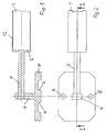
- Figures 1 and 2 show a first variant of a coupling connection with a rod-shaped connecting element in the region of an end portion 3, wherein a rigid rod member is provided as a coupling rod 1 with hollow profile 12, which is closed to the end portion 3 with a transverse wall 2.
- the end portion 3 is fixedly connected to the transverse wall 2.
- a support 4 is fixed without play by press fit, which ends with a foot part 5.
- the foot part 5 has fastening holes 6, as in Fig. 2 shown, and on its mounting side grooves 7 for establishing a positive connection either with an actuator (not shown) or a (not shown) of a resonance test bench.
- the section line II of Fig. 2 designates the cutting plane according to Fig. 1 ,
- Fig. 4 corresponds to those of the figures shown above.
- the section line III-III indicates the section plane according to Fig. 3 ,
- FIGS. 5 and 6 A third variant of the connecting element is in the FIGS. 5 and 6 shown, where FIG. 5 a sectional plane VV of the FIG. 6 equivalent.
- FIG. 5 In contrast to the second variant according to the FIGS. 3 and 4 shows FIG. 5 within the overhang tube 8 nor a bending tube 10 returning to it coaxially.
- the end section 3 is not firmly connected to the end wall 9.
- the returning bending tube 10 is fixed, whose inner end is supported by means of an inner support 15 on the foot part 5.
- the inner support 15 is connected along the axis 11 by a screw connection on the one hand with the returning bending tube 10 on the other hand with the foot part 5.
- the rod-shaped elastic end portion 3 is press-fitted to an outer support 14 at its outer end. Both the outer support 14 and the inner support 15 are passed with play through the overhang tube 8 and the returning bending tube 10.
- the elasticity of the joint connection with play-free coupling is further improved in the third variant.
Landscapes
- Physics & Mathematics (AREA)
- General Physics & Mathematics (AREA)
- Investigating Strength Of Materials By Application Of Mechanical Stress (AREA)
- Vibration Prevention Devices (AREA)
- Apparatuses For Generation Of Mechanical Vibrations (AREA)
Description
- Die Erfindung betrifft ein Verbindungselement zur Übertragung einer Erregerschwingung in einem Schwingungssystem, insbesondere eines Resonanzprüfstands gemäß dem Oberbegriff von Anspruch 1.
- Dabei geht es um die Übertragung periodisch oszillierender Kräfte auf einen Prüfling zwecks Verprobung von Schwingungsbelastungen auf Seiten des Prüflings.
- Das Verbindungselement ist dabei einerseits mit einem Aktuator zum Erzeugen der Erregerschwingung, andererseits mit dem Prüfling gekoppelt.
- Es wurde eine Vorrichtung zur Belastungsprüfung rotatorischer Prüflinge in Form von Radsätzen für Schienenfahrzeuge vorgeschlagen, bei der eine von Aktuatoren erzeugte Erregerschwingung mittels Koppelstäben auf den jeweiligen Prüfling übertragen wird. Diese Vorrichtung ist in der europäischen Patentanmeldung
EP 14001257 - Nach dem älteren Vorschlag sind zur Verprobung der Umlaufbiegung des Prüflings mindestens drei gleichmäßig über einen Kreisumfang um die Drehachse des Prüflings angeordnete Koppelstäbe vorgesehen, die im wesentlichen spielfrei einerseits mit einem Aktuator, andererseits mit dem Prüfling gekoppelt sind. Die Enden der Koppelstäbe sind dabei mittels einer dreh- und biegeelastischen Fügeverbindung derart spielfrei befestigt, dass die auf den Prüfling übertragenen Erregerkräfte der Erregerschwingung entsprechen. Von den über einen Kreisumfang um die Drehachse des Prüflings angeordneten Koppelstäben wird dabei durch das mechanische Einwirken der periodisch oszillierenden Erregerkräfte ein um die feststehende Drehachse des Prüflings umlaufendes Moment erzeugt.
- Ferner ist ein Verbindungselement der eingangs genannten Art in
US 2 228 499 A und inUS 7 013 731 B1 offenbart, welches einerseits mit einem Aktuator zur Erzeugung einer Erregerschwingung, andererseits mit dem Prüfling im Wesentlichen spielfrei gekoppelt ist. - Der vorliegenden Erfindung liegt demgegenüber die Aufgabe zugrunde, ein auf minimale Erregerkräfte ansprechendes Verbindungselement der eingangs genannten Art, dessen Koppelanschlüsse den Anforderungen hoher Elastizität bei geringer Baugröße entsprechen, zu schaffen, welches außerdem empfindlich anspricht, so dass es geeignet ist, die Regelbarkeit bei einem Prüfstand zu verbessern.
- Diese Aufgabe wird erfindungsgemäß durch Ausgestaltung des Verbindungselements gemäß dem Kennzeichen von Patentanspruch 1 gelöst. Dabei sind die Koppelanschlüsse im Wesentlichen spielfrei ausgestaltet, bevorzugt in Art einer dreh- und/oder biegeelastischen Fügeverbindung oder einer mechanischen Einspannung.
- Hinsichtlich der Ausgestaltung der Koppelanschlüsse geht es insbesondere darum, eine spielfreie Verbindung sowohl auf der Aktuatorseite als auch auf Seiten des Prüflings zu realisieren, dennoch aber eine für die Übertragung von Erregerkräften ausreichende Elastizität zu ermöglichen, ohne dass dabei die Sinusschwingung der Erregerkräfte durch Ausweichbewegungen im Bereich der Koppelanschlüsse nachteilig verändert wird.
- Das Verbindungselement selbst ist dabei im Wesentlichen stabförmig gestaltet ist, wobei ein oder beide Endabschnitte des Verbindungselements unter Einwirkung der Erregerschwingung elastisch verformbar ausgebildet sind.
- Vorteilhaft sind dabei die elastischen Endabschnitte mit beiden Enden eines im Wesentlichen biegesteifen Stabteil fest verbunden.
- Durch eine derartige Ausgestaltung stabförmiger Verbindungselemente werden diese einerseits in Richtung ihrer Längsachse in Art einer mechanischen Einspannung festgelegt; andererseits bleibt eine begrenzte Verformungsmöglichkeit im Bereich des jeweiligen Koppelanschlusses erhalten, so dass eine Dämpfung der Erregerschwingung weitgehend unterbleibt bzw. die Erregerschwingung in voller linearer Ausprägung mittels des Verbindungselements weitergeleitet wird.
- Der erfindungsgemäße Einsatz derartiger stabförmiger Verbindungselemente ermöglicht nicht nur die gezielte Anordnung ihres Kraftangriffs, derart, dass z.B. das Schwingungssystem auf den Prüfling in dessen dynamischen Verformungsnullpunkt des in Schwingung versetzten Hingegen kann der biegesteife Stabteil bevorzugt als Koppelstab mit Hohlprofil ausgebildet sein. Auf beiden Seiten des Koppelstabs sind die Endabschnitte fest mit dem Koppelstab verbunden.
- Eine bevorzugte, axial besonders stabile Ausführungsform des erfindungsgemäßen Verbindungselements besteht darin, dass die elastischen Endabschnitte jeweils mit ihrem Verbindungsende mit einer Querwand des Koppelstabes, mit ihrem äußeren Ende mit einer Endwand des Koppelstabes fest verbunden und mit Abstand von ihrem äußeren Ende an einer seitlich abkragenden mittleren Stütze befestigt sind, die sich mit Spiel durch die Wand des Hohlprofils erstreckt. Bei einer derartigen Ausführungsform ist die Mittelstütze bevorzugt mit Presssitz auf dem Endabschnitt befestigt. Die Größe der Durchtrittsöffnung der mittleren Stütze durch die Wand des Koppelstabs im Bereich seines als Überhangrohr ausgebildeten Rohrendes bemisst sich nach dem Kippwinkel der mittleren Stütze, die entweder auf dem Aktuator oder dem Prüfling befestigt ist. Im Rahmen einer spielfreien Befestigung des elastischen Endabschnitts sind Kippwinkel von < 1 Winkelgrad noch tolerierbar.
- Bei einer besonders elastischen Ausbildung des Koppelanschlusses an einem erfindungsgemäßen Verbindungselement ist vorgesehen,
- dass die elastischen Endabschnitte jeweils mit ihrem Verbindungsende mit einer Querwand des Koppelstabs fest verbunden sind,
- dass sein Hohlprofil den jeweiligen Endabschnitt in Art eines Überhangrohrs übergreift und mit einer Endwand verschlossen ist,
- dass der Endabschnitt nahe seinem äußeren Ende an einer seitlich abkragenden äußeren Stütze befestigt ist, die sich mit Spiel durch die Wand des Hohlprofils erstreckt, und
- dass ferner eine innere Stütze nahe der Querwand vorgesehen ist, welche im Inneren des Hohlprofils am freien Ende eines zum Endabschnitt parallel verlaufenden, mit der Endwand verbundenen Tragelements befestigt ist.
- Vorteilhaft ist das Tragelement als koaxial im Inneren des Hohlprofils angeordnetes Biegerohr ausgebildet, welches den Endabschnitt übergreift, und wobei sich die äußere Stütze mit Spiel auch durch das Biegerohr erstreckt. Dementsprechend ist dessen freies inneres Ende einerseits mit der inneren Stütze, andererseits mit der Endwand des Hohlprofils fest verbunden.
- Ohne Vergrößerung der Baulänge des Verbindungselements ist bei der Ausführungsform mit zum Hohlprofil konzentrisch rücklaufendem Biegerohr eine deutlich höhere Elastizität der im Wesentlichen spielfreien Koppelung sowohl gegenüber der oben beschriebenen Ausführungsform mit einfachem Überhangrohr als auch der Ausführungsform mit einem einfachen Biegestab ohne Überhangrohr gegeben.
- Im Folgenden werden die genannten Ausführungsbeispiele anhand der Zeichnung erläutert. Es zeigen jeweils in einem Axialschnitt und in der Draufsicht
- Figuren 1 und 2
- eine erste Variante mit stabförmigem Endabschnitt,
- Figuren 3 und 4
- eine zweite Variante mit Überhangrohr im Bereich des Endabschnitts und
- Figuren 5 und 6
- eine dritte Variante mit Überhangrohr und rücklaufendem Biegerohr im Bereich des Endabschnitts.
-
Figuren 1 und 2 zeigen eine erste Variante eines Koppelanschlusses mit einem stabförmigen Verbindungselement im Bereich eines Endabschnitts 3, wobei ein biegesteifer Stabteil als Koppelstab 1 mit Hohlprofil 12 vorgesehen ist, welches zum Endabschnitt 3 hin mit einer Querwand 2 verschlossen ist. Der Endabschnitt 3 ist mit der Querwand 2 fest verbunden. An seinem äußeren Ende ist eine Stütze 4 durch Presssitz spielfrei befestigt, welche mit einem Fußteil 5 endet. Der Fußteil 5 besitzt Befestigungsbohrungen 6, wie inFig. 2 gezeigt, und auf seiner Befestigungsseite Nuten 7 zum Herstellen einer formschlüssigen Verbindung entweder mit einem (nicht gezeigten) Aktuator oder einem (nicht gezeigten) Prüfling eines Resonanzprüfstands. - Die Schnittlinie I-I der
Fig. 2 bezeichnet die Schnittebene gemäßFig. 1 . - Unter der Einwirkung der vom Endabschnitt 3 in die Stütze 4 übertragenen Erregerschwingung sind geringfügige Ausweichbewegungen des äußeren Endes und der Stütze 4 im Rahmen der Elastizität dieser Bauteile infolge der Einwirkung von Erregerkräften zu tolerieren.
- Bei der in den
Figuren 3 und 4 dargestellten zweiten Variante des Koppelanschlusses eines Verbindungselements ist das den Koppelstab 1 bildende Hohlprofil 12 über eine Querwand 2 hinaus durch ein Überhangrohr 8 verlängert, welches mit einer Endwand 9 abschließt. Der stabförmige elastische Endabschnitt 3 ist mit seinem inneren Ende mit der Querwand 2, mit seinem äußeren Ende mit der Endwand 9 fest verbunden. In der Mitte ist der Endabschnitt 3 über einen Presssitz mit einer mittleren Stütze13 verbunden, die bei der ersten Variante mit einem Fußteil 5 endet. Die über den Koppelstab 1 übertragenen Erregerkräfte werden über den Endabschnitt 3 elastisch weitergeleitet und über die mittlere Stütze 13 und das Fußteil 5 übertragen bzw. in umgekehrter Richtung über die mittlere Stütze 13 in den Endabschnitt 3 eingeleitet und von dort über den Koppelstab 1 zu dessen (nicht gezeigten) entfernten Koppelanschluss weitergeleitet. - Die Bezugsziffern in
Fig. 4 entsprechen jenen der oben gezeigten Figuren. Die Schnittlinie III-III bezeichnet die Schnittebene gemäßFig. 3 . - Dadurch dass bei der in den
Figuren 3, 4 gezeigten zweiten Variante der Endabschnitt 3 im Inneren des Überhangrohrs 8 aufgenommen und beidseitig in zugeordneten Wandteilen befestigt ist, wird in idealer Weise eine spielfreie Koppelung bei einer dreh- und biegeelastischen Fügeverbindung verwirklicht. - Eine dritte Variante des Verbindungselements ist in den
Figuren 5 und 6 dargestellt, wobeiFigur 5 einer Schnittebene V-V derFigur 6 entspricht. - Im Unterschied zur zweiten Variante gemäß den
Figuren 3 und 4 zeigtFigur 5 innerhalb des Überhangrohrs 8 noch ein zu diesem koaxial rücklaufendes Biegerohr 10. Hier ist der Endabschnitt 3 nicht mit der Endwand 9 fest verbunden. An dieser ist jedoch das rücklaufende Biegerohr 10 befestigt, dessen inneres Ende mittels einer inneren Stütze 15 auf dem Fußteil 5 abgestützt ist. Die innere Stütze 15 ist längs der Achse 11 durch eine Schraubverbindung einerseits mit dem rücklaufenden Biegerohr 10 andererseits mit dem Fußteil 5 verbunden. Der stabförmige elastische Endabschnitt 3 ist an seinem äußeren Ende durch Presssitz mit einer äußeren Stütze 14 verbunden. Sowohl die äußere Stütze 14 als auch die innere Stütze 15 sind mit Spiel durch das Überhangrohr 8 bzw. das rücklaufende Biegerohr 10 hindurchgeführt. - In
Figur 6 sind die für gleiche Teile verwendeten Bezugsziffern der voranstehenden Figuren eingetragen. - Im Vergleich zu den beiden anderen Varianten wird bei der dritten Variante die Elastizität der Fügeverbindung bei spielfreier Koppelung weiter verbessert.
Claims (7)
- Verbindungselement zur Übertragung einer Erregerschwingung in einem Schwingungssystem, insbesondere eines Resonanzprüfstands, durch mechanisches Einwirken periodisch oszillierender Kräfte auf einen Prüfling, wobei das Verbindungselement einerseits mit einem Aktuator zur Erzeugung der Erregerschwingung, andererseits mit dem Prüfling im Wesentlichen spielfrei gekoppelt ist, derart, dass die auf den Prüfling übertragenen Kräfte der Erregerschwingung entsprechen,
dadurch gekennzeichnet,
dass das Verbindungselement im Wesentlichen stabförmig gestaltet ist, wobei ein oder beide seiner Endabschnitte (3) unter Einwirkung der Erregerschwingung elastisch verformbar ausgebildet und mittels einer Stütze (4, 13, 14) spielfrei gekoppelt sind. - Verbindungselement nach Anspruch 1,
dadurch gekennzeichnet,
dass die elastischen Endabschnitte (3) jeweils mit einem im Wesentlichen biegesteifen Stabteil fest verbunden sind. - Verbindungselement nach Anspruch 2,
dadurch gekennzeichnet,
dass die Länge des biegesteifen Stabteils der mehrfachen Länge eines Endabschnitts (3) entspricht. - Verbindungselement nach Anspruch 2,
dadurch gekennzeichnet,
dass der biegesteife Stabteil als Koppelstab (1) mit Hohlprofil (12) ausgebildet ist, welches den jeweiligen Endabschnitt (3) übergreift. - Verbindungselement nach Anspruch 4,
dadurch gekennzeichnet,
dass die elastischen Endabschnitte (3) jeweils mit ihrem Verbindungsende mit einer Querwand (2) des Koppelstabes (1), mit ihrem äußeren Ende mit einer Endwand (9) des Koppelstabs (1) fest verbunden und mit Abstand von ihrem äußeren Ende an einer seitlich abkragenden mittleren Stütze (13) befestigt sind, die sich mit Spiel durch die Wand des Hohlprofils (12) erstreckt. - Verbindungselement nach Anspruch 4,
dadurch gekennzeichnet,
dass der Endabschnitt (3) nahe seinem äußeren Ende an einer seitlich abkragenden äußeren Stütze (14) befestigt ist, die sich mit Spiel durch die Wand des Hohlprofils (12) erstreckt, und dass ferner eine innere Stütze (15) nahe der Querwand (2) vorgesehen ist, welche im Inneren des Hohlprofils (12) am freien Ende eines zum Endabschnitt (3) parallel verlaufenden, mit der Endwand (9) verbundenen Tragelements befestigt ist. - Verbindungselement nach Anspruch 6,
dadurch gekennzeichnet,
dass das Trageelement als koaxial im Inneren des Hohlprofils (12) angeordnetes Biegerohr (10) ausgebildet ist, welches den Endabschnitt (3) übergreift, und wobei sich die äußere Stütze (14) mit Spiel auch durch das Biegerohr (10) erstreckt.
Priority Applications (1)
| Application Number | Priority Date | Filing Date | Title |
|---|---|---|---|
| EP14001659.3A EP2930490B1 (de) | 2014-04-04 | 2014-05-12 | Verbindungselement zur Übertragung einer Erregerschwingung in einem Schwingsystem |
Applications Claiming Priority (2)
| Application Number | Priority Date | Filing Date | Title |
|---|---|---|---|
| EP14001257.6A EP2927660B1 (de) | 2014-04-04 | 2014-04-04 | Vorrichtung zur Belastungsprüfung rotatorischer Prüflinge |
| EP14001659.3A EP2930490B1 (de) | 2014-04-04 | 2014-05-12 | Verbindungselement zur Übertragung einer Erregerschwingung in einem Schwingsystem |
Publications (2)
| Publication Number | Publication Date |
|---|---|
| EP2930490A1 EP2930490A1 (de) | 2015-10-14 |
| EP2930490B1 true EP2930490B1 (de) | 2016-05-25 |
Family
ID=50442317
Family Applications (3)
| Application Number | Title | Priority Date | Filing Date |
|---|---|---|---|
| EP14001257.6A Active EP2927660B1 (de) | 2014-04-04 | 2014-04-04 | Vorrichtung zur Belastungsprüfung rotatorischer Prüflinge |
| EP14001657.7A Withdrawn EP2927661A3 (de) | 2014-04-04 | 2014-05-12 | Aktuator |
| EP14001659.3A Not-in-force EP2930490B1 (de) | 2014-04-04 | 2014-05-12 | Verbindungselement zur Übertragung einer Erregerschwingung in einem Schwingsystem |
Family Applications Before (2)
| Application Number | Title | Priority Date | Filing Date |
|---|---|---|---|
| EP14001257.6A Active EP2927660B1 (de) | 2014-04-04 | 2014-04-04 | Vorrichtung zur Belastungsprüfung rotatorischer Prüflinge |
| EP14001657.7A Withdrawn EP2927661A3 (de) | 2014-04-04 | 2014-05-12 | Aktuator |
Country Status (1)
| Country | Link |
|---|---|
| EP (3) | EP2927660B1 (de) |
Families Citing this family (16)
| Publication number | Priority date | Publication date | Assignee | Title |
|---|---|---|---|---|
| CN105910780B (zh) * | 2016-04-06 | 2018-04-10 | 重庆大学 | 一种精确可控非接触试件旋转式磁场疲劳激振与测振装置 |
| AT518412B1 (de) * | 2016-06-07 | 2017-10-15 | Prisma Eng Maschinen- Und Motorentechnik Gmbh | Schwinglast, Prüfstand zum Schwingungsprüfen und Verfahren hiefür |
| CN106370370B (zh) * | 2016-08-17 | 2019-01-25 | 中国航空工业集团公司西安飞行自动控制研究所 | 一种可快速转换的作动器振动试验夹具 |
| FR3057955A1 (fr) | 2016-10-21 | 2018-04-27 | Mg-Valdunes | Appareil pour tester un arbre et/ou une piece mecanique montee sur l'arbre et utilisation d'un tel appareil |
| CN106636609B (zh) * | 2017-01-20 | 2018-06-01 | 广西大学 | 一种凸轮冲击式交变力矩弯扭耦合共振式振动时效装置 |
| CN106636608B (zh) * | 2017-01-20 | 2018-06-05 | 广西大学 | 一种由电磁致动器激发的弯扭耦合共振式振动时效装置 |
| CN106702135B (zh) * | 2017-01-20 | 2018-06-01 | 广西大学 | 一种由偏心电机激发的弯扭耦合共振式残余应力消除装置 |
| CN106702136B (zh) * | 2017-01-20 | 2018-06-05 | 广西大学 | 圆柱凸轮激励引发的弯扭耦合共振式残余应力消除装置 |
| CN107290435B (zh) * | 2017-06-08 | 2020-03-03 | 浙江理工大学 | 一种用于旋转主轴裂纹检测的弹性波激发装置 |
| CN107388907A (zh) * | 2017-08-22 | 2017-11-24 | 天津航天瑞莱科技有限公司 | 一种导弹自转状态下的自由模态试验系统 |
| NL2020815B1 (en) * | 2018-04-24 | 2019-10-31 | Onderzoekscentrum Voor Aanwending Van Staal N V | Resonant fatigue testing |
| CN109855800A (zh) * | 2019-03-29 | 2019-06-07 | 国网山东省电力公司电力科学研究院 | 降低汽轮机转子残余应力释放引起的开机异常振动的方法 |
| CN111323197B (zh) * | 2020-03-25 | 2024-06-14 | 安徽三联学院 | 一种飞机轴系冲击振动模拟试验装置及其使用方法 |
| CN111829802B (zh) * | 2020-06-12 | 2024-07-30 | 江苏大学 | 一种多滚筒动平衡振动耦合试验台及试验方法 |
| CN117871001B (zh) * | 2023-12-18 | 2024-07-23 | 中国科学院空间应用工程与技术中心 | 一种实验舱导向机构用滚轮的动态振动测试装置 |
| CN118837032B (zh) * | 2024-09-24 | 2024-12-13 | 潍坊学院 | 一种基于振动测试的锥箱故障诊断装置及方法 |
Family Cites Families (7)
| Publication number | Priority date | Publication date | Assignee | Title |
|---|---|---|---|---|
| US2228499A (en) * | 1936-12-30 | 1941-01-14 | Bosch Gmbh Robert | Apparatus for the vibration testing of articles |
| DE2601259C3 (de) | 1976-01-15 | 1979-03-29 | Fraunhofer-Gesellschaft Zur Foerderung Der Angewandten Forschung E.V., 8000 Muenchen | Einrichtung zur betriebsähnlichen Prüfung von Radsätzen |
| US6247366B1 (en) * | 1997-09-15 | 2001-06-19 | Alexander J. Porter | Design maturity algorithm |
| US6035715A (en) * | 1997-09-15 | 2000-03-14 | Entela, Inc, | Method and apparatus for optimizing the design of a product |
| US7013731B1 (en) * | 2004-10-15 | 2006-03-21 | Western Digital Technologies, Inc. | Data storage testing apparatus for delivering linear or rotational acceleration |
| DE102010027897B4 (de) | 2010-04-19 | 2013-02-28 | Sven Henze | Schwingungsprüfeinrichtung |
| ES2363549B1 (es) * | 2011-03-08 | 2012-03-23 | Instituto Tecnológico Del Embalaje, Transporte Y Log�?Stica | M�?quina simuladora de movimiento producido durante el transporte |
-
2014
- 2014-04-04 EP EP14001257.6A patent/EP2927660B1/de active Active
- 2014-05-12 EP EP14001657.7A patent/EP2927661A3/de not_active Withdrawn
- 2014-05-12 EP EP14001659.3A patent/EP2930490B1/de not_active Not-in-force
Also Published As
| Publication number | Publication date |
|---|---|
| EP2927660B1 (de) | 2016-10-12 |
| EP2927661A2 (de) | 2015-10-07 |
| EP2927660A1 (de) | 2015-10-07 |
| EP2927661A3 (de) | 2015-10-28 |
| EP2930490A1 (de) | 2015-10-14 |
Similar Documents
| Publication | Publication Date | Title |
|---|---|---|
| EP2930490A1 (de) | Verbindungselement zur Übertragung einer Erregerschwingung in einem Schwingsystem | |
| WO2020108681A1 (de) | Aktuator für eine hinterachslenkung eines fahrzeugs sowie hinterachslenkung mit einem solchen aktuator | |
| DE102016104188B4 (de) | Vorrichtung zum Aktivieren von mindestens einer Funktionskomponente einer automatischen Mittelpufferkupplung | |
| DE102009042150A1 (de) | Chirurgisches Instrument | |
| DE102017217631B3 (de) | Aktuator einer Lenkung sowie steer-by-wire-Lenkung eines Kraftfahrzeuges | |
| DE102019216750A1 (de) | Prüfstand | |
| DE102008056662B4 (de) | Segmentkörper und Abstreifer für einen Fördergurtabstreifer | |
| AT517763B1 (de) | Anordnung zur Drehverbindung einer Belastungsmaschine eines Prüfstandes mit einem Prüfling | |
| WO2012098108A1 (de) | Laschenkupplung | |
| DE102007012772B4 (de) | Elastisches Lagerelement | |
| DE69208440T2 (de) | Zylindrische Elastomer-Lager-Anlage mit grossem WInkelausschlag | |
| EP3325835B1 (de) | Wellenverbindungsvorrichtung und anordnung zur drehverbindung einer belastungsmaschine eines prüfstandes mit einem prüfling | |
| EP2525928B1 (de) | Strangführungselement zum führen und stützen eines metallischen strangs in einer stranggiessmaschine | |
| EP0342260B1 (de) | Flexible Kupplung für intermittierenden Betrieb, wie Schalterantrieb | |
| DE102010039198A1 (de) | Schüttelvorrichtung | |
| DE2807007C2 (de) | Querkupplungsanordnung für ein Schienenfahrzeug mit mindestens zwei Fahrgestellen | |
| EP4547129B1 (de) | Chirurgisches instrument und verfahren zu dessen zerlegung | |
| CH332932A (de) | Einrichtung zur torsionsfesten und doch lösbaren Verbindung von Lagerzapfen mit den Metallinnenhülsen von Gummilagerbüchsen | |
| DE102008000867A1 (de) | Kardangelenk mit Radialausgleich | |
| DE102006001191B4 (de) | Kreuzgelenk | |
| DE102010054947A1 (de) | Vorrichtung zum Montieren und Demontieren eines Sicherungsstifts in Prüfbolzen von Wälzlagern | |
| CH695041A5 (de) | Vorrichtung zur Simulation eines stabförmigen chirurgischen Instrumentes mit Kraftrückkopplung. | |
| WO2023057153A1 (de) | Vorrichtung und verfahren zum in-situ testen von probenmaterial unter einer schnellen wechselbelastung | |
| WO2024110122A1 (de) | Längeneinstellbares fahrwerkbauteil sowie verfahren zur vormontage eines längeneinstellbaren fahrwerkbauteils | |
| DE846205C (de) | Gleichgang-Gelenk, insbesondere fuer den Antrieb von Lenkraedern an Kraftfahrzeugen |
Legal Events
| Date | Code | Title | Description |
|---|---|---|---|
| PUAI | Public reference made under article 153(3) epc to a published international application that has entered the european phase |
Free format text: ORIGINAL CODE: 0009012 |
|
| AK | Designated contracting states |
Kind code of ref document: A1 Designated state(s): AL AT BE BG CH CY CZ DE DK EE ES FI FR GB GR HR HU IE IS IT LI LT LU LV MC MK MT NL NO PL PT RO RS SE SI SK SM TR |
|
| AX | Request for extension of the european patent |
Extension state: BA ME |
|
| 17P | Request for examination filed |
Effective date: 20151006 |
|
| RBV | Designated contracting states (corrected) |
Designated state(s): AL AT BE BG CH CY CZ DE DK EE ES FI FR GB GR HR HU IE IS IT LI LT LU LV MC MK MT NL NO PL PT RO RS SE SI SK SM TR |
|
| GRAP | Despatch of communication of intention to grant a patent |
Free format text: ORIGINAL CODE: EPIDOSNIGR1 |
|
| INTG | Intention to grant announced |
Effective date: 20160203 |
|
| GRAS | Grant fee paid |
Free format text: ORIGINAL CODE: EPIDOSNIGR3 |
|
| GRAA | (expected) grant |
Free format text: ORIGINAL CODE: 0009210 |
|
| AK | Designated contracting states |
Kind code of ref document: B1 Designated state(s): AL AT BE BG CH CY CZ DE DK EE ES FI FR GB GR HR HU IE IS IT LI LT LU LV MC MK MT NL NO PL PT RO RS SE SI SK SM TR |
|
| REG | Reference to a national code |
Ref country code: GB Ref legal event code: FG4D Free format text: NOT ENGLISH |
|
| REG | Reference to a national code |
Ref country code: CH Ref legal event code: EP Ref country code: CH Ref legal event code: NV Representative=s name: GRAETTINGER MOEHRING VON POSCHINGER PATENTANWA, CH |
|
| REG | Reference to a national code |
Ref country code: IE Ref legal event code: FG4D Free format text: LANGUAGE OF EP DOCUMENT: GERMAN Ref country code: AT Ref legal event code: REF Ref document number: 802699 Country of ref document: AT Kind code of ref document: T Effective date: 20160615 |
|
| REG | Reference to a national code |
Ref country code: DE Ref legal event code: R096 Ref document number: 502014000806 Country of ref document: DE |
|
| REG | Reference to a national code |
Ref country code: LT Ref legal event code: MG4D |
|
| REG | Reference to a national code |
Ref country code: NL Ref legal event code: MP Effective date: 20160525 |
|
| PG25 | Lapsed in a contracting state [announced via postgrant information from national office to epo] |
Ref country code: NO Free format text: LAPSE BECAUSE OF FAILURE TO SUBMIT A TRANSLATION OF THE DESCRIPTION OR TO PAY THE FEE WITHIN THE PRESCRIBED TIME-LIMIT Effective date: 20160825 Ref country code: NL Free format text: LAPSE BECAUSE OF FAILURE TO SUBMIT A TRANSLATION OF THE DESCRIPTION OR TO PAY THE FEE WITHIN THE PRESCRIBED TIME-LIMIT Effective date: 20160525 Ref country code: FI Free format text: LAPSE BECAUSE OF FAILURE TO SUBMIT A TRANSLATION OF THE DESCRIPTION OR TO PAY THE FEE WITHIN THE PRESCRIBED TIME-LIMIT Effective date: 20160525 Ref country code: LT Free format text: LAPSE BECAUSE OF FAILURE TO SUBMIT A TRANSLATION OF THE DESCRIPTION OR TO PAY THE FEE WITHIN THE PRESCRIBED TIME-LIMIT Effective date: 20160525 |
|
| PG25 | Lapsed in a contracting state [announced via postgrant information from national office to epo] |
Ref country code: ES Free format text: LAPSE BECAUSE OF FAILURE TO SUBMIT A TRANSLATION OF THE DESCRIPTION OR TO PAY THE FEE WITHIN THE PRESCRIBED TIME-LIMIT Effective date: 20160525 Ref country code: PT Free format text: LAPSE BECAUSE OF FAILURE TO SUBMIT A TRANSLATION OF THE DESCRIPTION OR TO PAY THE FEE WITHIN THE PRESCRIBED TIME-LIMIT Effective date: 20160926 Ref country code: LV Free format text: LAPSE BECAUSE OF FAILURE TO SUBMIT A TRANSLATION OF THE DESCRIPTION OR TO PAY THE FEE WITHIN THE PRESCRIBED TIME-LIMIT Effective date: 20160525 Ref country code: SE Free format text: LAPSE BECAUSE OF FAILURE TO SUBMIT A TRANSLATION OF THE DESCRIPTION OR TO PAY THE FEE WITHIN THE PRESCRIBED TIME-LIMIT Effective date: 20160525 Ref country code: GR Free format text: LAPSE BECAUSE OF FAILURE TO SUBMIT A TRANSLATION OF THE DESCRIPTION OR TO PAY THE FEE WITHIN THE PRESCRIBED TIME-LIMIT Effective date: 20160826 Ref country code: RS Free format text: LAPSE BECAUSE OF FAILURE TO SUBMIT A TRANSLATION OF THE DESCRIPTION OR TO PAY THE FEE WITHIN THE PRESCRIBED TIME-LIMIT Effective date: 20160525 |
|
| PG25 | Lapsed in a contracting state [announced via postgrant information from national office to epo] |
Ref country code: CZ Free format text: LAPSE BECAUSE OF FAILURE TO SUBMIT A TRANSLATION OF THE DESCRIPTION OR TO PAY THE FEE WITHIN THE PRESCRIBED TIME-LIMIT Effective date: 20160525 Ref country code: EE Free format text: LAPSE BECAUSE OF FAILURE TO SUBMIT A TRANSLATION OF THE DESCRIPTION OR TO PAY THE FEE WITHIN THE PRESCRIBED TIME-LIMIT Effective date: 20160525 Ref country code: SK Free format text: LAPSE BECAUSE OF FAILURE TO SUBMIT A TRANSLATION OF THE DESCRIPTION OR TO PAY THE FEE WITHIN THE PRESCRIBED TIME-LIMIT Effective date: 20160525 Ref country code: DK Free format text: LAPSE BECAUSE OF FAILURE TO SUBMIT A TRANSLATION OF THE DESCRIPTION OR TO PAY THE FEE WITHIN THE PRESCRIBED TIME-LIMIT Effective date: 20160525 Ref country code: RO Free format text: LAPSE BECAUSE OF FAILURE TO SUBMIT A TRANSLATION OF THE DESCRIPTION OR TO PAY THE FEE WITHIN THE PRESCRIBED TIME-LIMIT Effective date: 20160525 |
|
| PG25 | Lapsed in a contracting state [announced via postgrant information from national office to epo] |
Ref country code: SM Free format text: LAPSE BECAUSE OF FAILURE TO SUBMIT A TRANSLATION OF THE DESCRIPTION OR TO PAY THE FEE WITHIN THE PRESCRIBED TIME-LIMIT Effective date: 20160525 Ref country code: PL Free format text: LAPSE BECAUSE OF FAILURE TO SUBMIT A TRANSLATION OF THE DESCRIPTION OR TO PAY THE FEE WITHIN THE PRESCRIBED TIME-LIMIT Effective date: 20160525 |
|
| REG | Reference to a national code |
Ref country code: DE Ref legal event code: R097 Ref document number: 502014000806 Country of ref document: DE |
|
| PLBE | No opposition filed within time limit |
Free format text: ORIGINAL CODE: 0009261 |
|
| STAA | Information on the status of an ep patent application or granted ep patent |
Free format text: STATUS: NO OPPOSITION FILED WITHIN TIME LIMIT |
|
| 26N | No opposition filed |
Effective date: 20170228 |
|
| REG | Reference to a national code |
Ref country code: FR Ref legal event code: PLFP Year of fee payment: 4 |
|
| PG25 | Lapsed in a contracting state [announced via postgrant information from national office to epo] |
Ref country code: SI Free format text: LAPSE BECAUSE OF FAILURE TO SUBMIT A TRANSLATION OF THE DESCRIPTION OR TO PAY THE FEE WITHIN THE PRESCRIBED TIME-LIMIT Effective date: 20160525 |
|
| PG25 | Lapsed in a contracting state [announced via postgrant information from national office to epo] |
Ref country code: LU Free format text: LAPSE BECAUSE OF NON-PAYMENT OF DUE FEES Effective date: 20170531 |
|
| REG | Reference to a national code |
Ref country code: CH Ref legal event code: PCAR Free format text: NEW ADDRESS: LOCHSTRASSE 19, 8268 SALENSTEIN (CH) |
|
| PG25 | Lapsed in a contracting state [announced via postgrant information from national office to epo] |
Ref country code: MC Free format text: LAPSE BECAUSE OF FAILURE TO SUBMIT A TRANSLATION OF THE DESCRIPTION OR TO PAY THE FEE WITHIN THE PRESCRIBED TIME-LIMIT Effective date: 20160525 |
|
| REG | Reference to a national code |
Ref country code: IE Ref legal event code: MM4A |
|
| PG25 | Lapsed in a contracting state [announced via postgrant information from national office to epo] |
Ref country code: LU Free format text: LAPSE BECAUSE OF NON-PAYMENT OF DUE FEES Effective date: 20170512 |
|
| REG | Reference to a national code |
Ref country code: BE Ref legal event code: MM Effective date: 20170531 |
|
| PG25 | Lapsed in a contracting state [announced via postgrant information from national office to epo] |
Ref country code: IE Free format text: LAPSE BECAUSE OF NON-PAYMENT OF DUE FEES Effective date: 20170512 |
|
| REG | Reference to a national code |
Ref country code: FR Ref legal event code: PLFP Year of fee payment: 5 |
|
| PG25 | Lapsed in a contracting state [announced via postgrant information from national office to epo] |
Ref country code: BE Free format text: LAPSE BECAUSE OF NON-PAYMENT OF DUE FEES Effective date: 20170531 |
|
| PG25 | Lapsed in a contracting state [announced via postgrant information from national office to epo] |
Ref country code: MT Free format text: LAPSE BECAUSE OF FAILURE TO SUBMIT A TRANSLATION OF THE DESCRIPTION OR TO PAY THE FEE WITHIN THE PRESCRIBED TIME-LIMIT Effective date: 20160525 |
|
| PG25 | Lapsed in a contracting state [announced via postgrant information from national office to epo] |
Ref country code: AL Free format text: LAPSE BECAUSE OF FAILURE TO SUBMIT A TRANSLATION OF THE DESCRIPTION OR TO PAY THE FEE WITHIN THE PRESCRIBED TIME-LIMIT Effective date: 20160525 |
|
| PG25 | Lapsed in a contracting state [announced via postgrant information from national office to epo] |
Ref country code: HU Free format text: LAPSE BECAUSE OF FAILURE TO SUBMIT A TRANSLATION OF THE DESCRIPTION OR TO PAY THE FEE WITHIN THE PRESCRIBED TIME-LIMIT; INVALID AB INITIO Effective date: 20140512 |
|
| PG25 | Lapsed in a contracting state [announced via postgrant information from national office to epo] |
Ref country code: BG Free format text: LAPSE BECAUSE OF FAILURE TO SUBMIT A TRANSLATION OF THE DESCRIPTION OR TO PAY THE FEE WITHIN THE PRESCRIBED TIME-LIMIT Effective date: 20160525 |
|
| PG25 | Lapsed in a contracting state [announced via postgrant information from national office to epo] |
Ref country code: CY Free format text: LAPSE BECAUSE OF FAILURE TO SUBMIT A TRANSLATION OF THE DESCRIPTION OR TO PAY THE FEE WITHIN THE PRESCRIBED TIME-LIMIT Effective date: 20160525 |
|
| PG25 | Lapsed in a contracting state [announced via postgrant information from national office to epo] |
Ref country code: MK Free format text: LAPSE BECAUSE OF FAILURE TO SUBMIT A TRANSLATION OF THE DESCRIPTION OR TO PAY THE FEE WITHIN THE PRESCRIBED TIME-LIMIT Effective date: 20160525 |
|
| PG25 | Lapsed in a contracting state [announced via postgrant information from national office to epo] |
Ref country code: TR Free format text: LAPSE BECAUSE OF FAILURE TO SUBMIT A TRANSLATION OF THE DESCRIPTION OR TO PAY THE FEE WITHIN THE PRESCRIBED TIME-LIMIT Effective date: 20160525 |
|
| PG25 | Lapsed in a contracting state [announced via postgrant information from national office to epo] |
Ref country code: HR Free format text: LAPSE BECAUSE OF FAILURE TO SUBMIT A TRANSLATION OF THE DESCRIPTION OR TO PAY THE FEE WITHIN THE PRESCRIBED TIME-LIMIT Effective date: 20160525 |
|
| PG25 | Lapsed in a contracting state [announced via postgrant information from national office to epo] |
Ref country code: IS Free format text: LAPSE BECAUSE OF FAILURE TO SUBMIT A TRANSLATION OF THE DESCRIPTION OR TO PAY THE FEE WITHIN THE PRESCRIBED TIME-LIMIT Effective date: 20160925 |
|
| REG | Reference to a national code |
Ref country code: DE Ref legal event code: R081 Ref document number: 502014000806 Country of ref document: DE Owner name: PRISMA ENGINEERING MASCHINEN- UND MOTORENTECHN, AT Free format text: FORMER OWNER: PRISMA ENGINEERING MASCHINEN- UND MOTORENTECHNIK GMBH, GRAZ, AT |
|
| REG | Reference to a national code |
Ref country code: AT Ref legal event code: PC Ref document number: 802699 Country of ref document: AT Kind code of ref document: T Owner name: PRISMA ENINEERING MASCHINEN- UND MOTORENTECHNI, AT Effective date: 20211103 |
|
| REG | Reference to a national code |
Ref country code: GB Ref legal event code: 732E Free format text: REGISTERED BETWEEN 20211202 AND 20211209 |
|
| PGFP | Annual fee paid to national office [announced via postgrant information from national office to epo] |
Ref country code: IT Payment date: 20220531 Year of fee payment: 9 Ref country code: GB Payment date: 20220523 Year of fee payment: 9 Ref country code: FR Payment date: 20220523 Year of fee payment: 9 Ref country code: DE Payment date: 20220519 Year of fee payment: 9 |
|
| PGFP | Annual fee paid to national office [announced via postgrant information from national office to epo] |
Ref country code: CH Payment date: 20220523 Year of fee payment: 9 Ref country code: AT Payment date: 20220428 Year of fee payment: 9 |
|
| REG | Reference to a national code |
Ref country code: DE Ref legal event code: R119 Ref document number: 502014000806 Country of ref document: DE |
|
| REG | Reference to a national code |
Ref country code: CH Ref legal event code: PL |
|
| REG | Reference to a national code |
Ref country code: AT Ref legal event code: MM01 Ref document number: 802699 Country of ref document: AT Kind code of ref document: T Effective date: 20230512 |
|
| GBPC | Gb: european patent ceased through non-payment of renewal fee |
Effective date: 20230512 |
|
| PG25 | Lapsed in a contracting state [announced via postgrant information from national office to epo] |
Ref country code: LI Free format text: LAPSE BECAUSE OF NON-PAYMENT OF DUE FEES Effective date: 20230531 Ref country code: CH Free format text: LAPSE BECAUSE OF NON-PAYMENT OF DUE FEES Effective date: 20230531 Ref country code: AT Free format text: LAPSE BECAUSE OF NON-PAYMENT OF DUE FEES Effective date: 20230512 |
|
| PG25 | Lapsed in a contracting state [announced via postgrant information from national office to epo] |
Ref country code: IT Free format text: LAPSE BECAUSE OF NON-PAYMENT OF DUE FEES Effective date: 20230512 Ref country code: DE Free format text: LAPSE BECAUSE OF NON-PAYMENT OF DUE FEES Effective date: 20231201 Ref country code: GB Free format text: LAPSE BECAUSE OF NON-PAYMENT OF DUE FEES Effective date: 20230512 |
|
| PG25 | Lapsed in a contracting state [announced via postgrant information from national office to epo] |
Ref country code: FR Free format text: LAPSE BECAUSE OF NON-PAYMENT OF DUE FEES Effective date: 20230531 |