EP2929987A1 - Etabli de travail pour des batteries electrochimiques, comportant un bac à eau disposé en-dessous - Google Patents
Etabli de travail pour des batteries electrochimiques, comportant un bac à eau disposé en-dessous Download PDFInfo
- Publication number
- EP2929987A1 EP2929987A1 EP15159384.5A EP15159384A EP2929987A1 EP 2929987 A1 EP2929987 A1 EP 2929987A1 EP 15159384 A EP15159384 A EP 15159384A EP 2929987 A1 EP2929987 A1 EP 2929987A1
- Authority
- EP
- European Patent Office
- Prior art keywords
- work
- grating
- descent
- bench according
- plane
- Prior art date
- Legal status (The legal status is an assumption and is not a legal conclusion. Google has not performed a legal analysis and makes no representation as to the accuracy of the status listed.)
- Granted
Links
Images
Classifications
-
- B—PERFORMING OPERATIONS; TRANSPORTING
- B25—HAND TOOLS; PORTABLE POWER-DRIVEN TOOLS; MANIPULATORS
- B25H—WORKSHOP EQUIPMENT, e.g. FOR MARKING-OUT WORK; STORAGE MEANS FOR WORKSHOPS
- B25H1/00—Work benches; Portable stands or supports for positioning portable tools or work to be operated on thereby
- B25H1/14—Work benches; Portable stands or supports for positioning portable tools or work to be operated on thereby with provision for adjusting the bench top
- B25H1/16—Work benches; Portable stands or supports for positioning portable tools or work to be operated on thereby with provision for adjusting the bench top in height
-
- Y—GENERAL TAGGING OF NEW TECHNOLOGICAL DEVELOPMENTS; GENERAL TAGGING OF CROSS-SECTIONAL TECHNOLOGIES SPANNING OVER SEVERAL SECTIONS OF THE IPC; TECHNICAL SUBJECTS COVERED BY FORMER USPC CROSS-REFERENCE ART COLLECTIONS [XRACs] AND DIGESTS
- Y02—TECHNOLOGIES OR APPLICATIONS FOR MITIGATION OR ADAPTATION AGAINST CLIMATE CHANGE
- Y02E—REDUCTION OF GREENHOUSE GAS [GHG] EMISSIONS, RELATED TO ENERGY GENERATION, TRANSMISSION OR DISTRIBUTION
- Y02E60/00—Enabling technologies; Technologies with a potential or indirect contribution to GHG emissions mitigation
- Y02E60/10—Energy storage using batteries
Definitions
- the present invention relates to a work bench provided for receiving electrochemical batteries.
- Hybrid or electric vehicles comprise, for traction, energy accumulators comprising electrochemical cells, hereinafter referred to as batteries, which can be produced using various known technologies.
- the batteries allow in particular to recover energy produced during the braking of the vehicle, to subsequently deliver a current to an electric traction motor.
- the batteries can also be recharged directly from an external electricity distribution network.
- the electrochemical cells can emit in this case liquids or hot gases under pressure, which are toxic and flammable. There is then a risk of starting a fire.
- this type of battery generally has a volume and a large mass. They then require lifting means, and can not be maneuvered quickly and easily.
- the workstation can be closed, surrounded by partitions and fire doors. However, if the fire can be confined, quick extinguishing means are still to be expected.
- the present invention is intended to avoid these disadvantages of the prior art.
- a work bench for electrochemical batteries comprising an electrically insulated work surface which is provided to receive the battery, characterized in that it comprises a water tray disposed below the work plane, and descent means of this plane in the tray.
- An advantage of this work bench is that on the one hand we can work normally on the battery by arranging the work plan at a height suitable for operator interventions, and secondly on a simple control placed on the station or operated remotely, it can very quickly immerse the battery fully in water by the descent of the work plane, which cools it effectively, prevents any fire, and the discharge electrically up to it no longer presents an electrical hazard.
- the operator can after the command to move away very quickly from the workstation, and trigger ventilation of the workplace, which ensures the safety of people.
- the workbench according to the invention may further comprise one or more of the following features, which may be combined with one another.
- the descent means of the work plane in the tray comprise a motorized actuating mechanism.
- the workbench advantageously comprises an autonomous energy reserve allowing at least one operation of the motorized actuating mechanism to perform a descent of the work plane, in the absence of external power supply.
- the descent speed of the work plane is controlled by the motorized actuating mechanism.
- the motorized actuating mechanism also carries out the ascent of the work plane.
- the worktop is held at the working height by locks.
- the work bench comprises a remote control descent of the work plane, for remote control of the descent of this plane.
- the work surface can be formed by an electrically insulated grating.
- the work bench has a grid fixed under the grating.
- the grating comprises a molded plastic surface, reinforced by a metal structure.
- the Figures 1 and 2 have a grating 2 forming an electrically insulated work plane for a voltage of 500V, which may be in particular polypropylene reinforced below by a metal frame to obtain insulation and rigidity, or wood.
- a mesh with 5 mm 2 mesh is fixed under the grating 2, to recover small pieces that fall on the grating without losing them below.
- the grating 2 can be sized to support batteries of maximum dimension of 950 by 1450mm, with a mass of 250kg, which can meet most of the needs of electric and hybrid vehicles.
- the grating 2 is held by four locks 10 at the upper level of a water tank 4 of parallelepipedal shape, electrically isolated, which is placed on a base 6 having two lateral passages 8 allowing the insertion of the arms of a forklift to move the entire workstation.
- the base 6 comprising a metal structure designed to support a mass of 1000kg, gives rigidity to the water tank 4. This base 6 has four hooks not shown, allowing a lift of the assembly.
- the water tank 4 can advantageously be made economically polypropylene material that retains its mechanical characteristics up to a temperature of 80 ° C.
- the water tank 4 also comprises four unrepresented lifting hooks, which allow to lift it empty to take it out of its base 6.
- the water tank 4 comprises a manual water inlet and outlet valve 20, connected by an external pipe to a supply or a sewer, which allows the filling or emptying of this tank.
- a temperature probe immersed in the water of the tank 4 measures the temperature of this water, which is indicated on a front display 22.
- the work surface formed by the surface of the grating 2 is advantageously arranged at a height of 950 mm, which allows an operator to intervene easily and ergonomically on a battery placed on it.
- An intermediate space 14 between the base 6 and the water tank 4 receives a pneumatic actuation mechanism, supplied at a pressure of at least 6 bars by an external pipe connected to an inlet 16 comprising a pressure gauge indicating the pressure of the supply circuit. .
- the workstation has after the inlet 16 a check valve maintaining the air pressure inside, then a pressure accumulator allowing in case of interruption of the external power supply, to store 25 liters of air at a minimum pressure of 5 bar for at least 8 hours.
- the actuating mechanism comprises pneumatic cylinders acting on cables 18, which make it possible, from a descent control, to open the bolts 10 in order to lower the grating 2 by letting the cables run in a controlled manner, and from a rising control to pull on these cables to reassemble this grating.
- a control panel 32 on the front panel of the water tank 4 includes an indicator of the internal air pressure 24 in the workstation, a climb control of the grating 26 and a control of descent of this grating 28.
- a remote descent control 30 of the grating 2 remote control the descent of the grating.
- the controls 26, 28, 30 are connected by pipes to an air distributor located in the desk 32, which is itself connected by pipes 12 to the four locks 10, which allows it to control the opening or the closing these locks according to the order.
- the remote control 30 can be connected to the workstation by a wireless communication means or pipe.
- the operation of the workstation is as follows. After removal of the battery on the grating 2 by an external handling means, the operator can work at a suitable height on this battery.
- the operator in front of the station actuates the descent control 28 of the desk 32, or a remote operator actuates the remote control 30.
- an automatic control that autonomously detects by means of sensors that the battery is overheated too much, or a start of fire, can be installed to automatically control the descent of the grating 2. This ensures safety even in the absence staff on site.
- the speed of descent of the grating 2 is controlled empty as in load, by the pneumatic actuating mechanism which lets the cables 18 spin at a controlled speed in order to obtain a descent into the water with a time of less than one minute.
- the volume of water residing in the water tank 4 is provided to sufficiently cool the batteries having a large mass which has reached a high temperature. In practice, a volume of water of approximately 700 liters can be provided.
- the water tray 4 has on the side opposite the console, a water level indicator.
- the pneumatic actuation mechanism also ensures by its cylinders the raising of the grating 2 after an action on the climb control 26, which allows to easily and effortlessly put the workstation back into its original configuration.
- This provides an ergonomic workstation with a small footprint, which ensures safety for work on electrochemical batteries with risks of ignition, especially lithium-ion batteries. Note that the environment of the workstation including the local implementation, does not require special adaptation to ensure this security.
- the water in the tray 4 may be contained in a sealed bag disposed at the bottom of the tray, which is pierced when triggering the descent of the grating 2. This pocket keeps the water reserve separately and protected during the entire period of non-use, which avoids polluting it, and prevents its evaporation.
- latches 10 holding the grating 2 which are manually operated by an operator to control the descent of the grating.
- the lift of the grating 2 is also done manually. This gives a workstation that does not use an external source of energy.
- the descent of the quail 2 can then be controlled by a fully mechanical braking device, with elastic stops, or end-of-travel cylinders arranged at the bottom of the tray 4 for its stop.
- the pneumatic energy reserve is a single-use compressed air tank.
- the holding time of the air reserve at the pressure of 6 bars is thus extended by more than one year.
- the workstation can be used independently, without external pneumatic energy input.
- a connection to an external power source then allows to go up the grating 2 with the control 26. To return the work bench to its initial state of operation, it is then sufficient to replace the cylinder used by a new cylinder.
- an electromechanical control system may be used in place of the pneumatic system, which performs the same functions.
Landscapes
- Engineering & Computer Science (AREA)
- Mechanical Engineering (AREA)
- Battery Mounting, Suspending (AREA)
Abstract
Description
- La présente invention concerne un établi de travail prévu pour recevoir des batteries électrochimiques.
- Les véhicules hybrides ou électriques comportent pour la traction des accumulateurs d'énergie comprenant des cellules électrochimiques, appelées par la suite batteries, qui peuvent être réalisées suivant différentes technologies connues.
- Les batteries permettent notamment de récupérer une énergie produite lors des freinages du véhicule, pour délivrer par la suite un courant à un moteur électrique de traction. Sur certains véhicules, les batteries peuvent aussi être rechargées directement à partir d'un réseau extérieur de distribution d'électricité.
- Suivant la technologie de batterie utilisée, en particulier pour les cellules électrochimiques au lithium-ion disposant d'une forte densité d'énergie par rapport à la masse, ces cellules présentent un risque de court-circuit interne en cas d'erreur de manipulation de différentes natures. On peut obtenir notamment un court-circuit interne avec un objet électriquement conducteur, une surcharge par un appareil défectueux, une chute accidentelle, un percement accidentel de la paroi externe.
- Ce court-circuit peut engendrer un emballement thermique qui se traduit par une forte élévation de la température. Les cellules électrochimiques peuvent émettre dans ce cas des liquides ou des gaz chauds sous pression, qui sont toxiques et inflammables. Il y a alors un risque de départ d'incendie.
- Par ailleurs pour effectuer des opérations sur ce type de batterie, notamment des tests, de la maintenance ou des réparations, réalisées par exemple au bureau d'études du constructeur automobile, ou dans les ateliers de montage ou d'entretien des véhicules, on dépose ces batteries sur un établi afin de les installer à une hauteur convenable facilitant le travail d'un opérateur.
- On notera que ce type de batterie comporte généralement un volume et une masse importante. Elles nécessitent alors des moyens de levage, et ne peuvent pas être manoeuvrées rapidement et facilement.
- Il est connu de prévoir à proximité du poste de travail des moyens de lutte contre le feu permettant d'intervenir en cas de départ d'incendie sur la batterie, comme un extincteur à gaz carbonique, une lance à eau appelée « Robinet d'Incendie Armé », ou des buses d'aspersion automatique d'eau installées au plafond, appelées « sprinklers ».
- En cas d'emballement thermique qui échauffe fortement une masse importante de la batterie, ces différentes solutions d'aspersion permettent d'attaquer un feu naissant en empêchant son extension. Toutefois elles ne permettent pas de contenir l'incendie sur la durée, et de rendre la batterie électriquement inerte.
- On peut aussi prévoir à proximité du poste de travail une piscine remplie d'eau. Il faut alors déplacer la batterie pour la plonger dedans, en prévoyant des moyens de manutention, ce qui n'est pas toujours très rapide à réaliser, et sûr pour l'opérateur en cas d'incendie dégageant des gaz toxiques. De plus cette installation est encombrante et onéreuse.
- Par ailleurs le poste de travail peut être clos, entouré de cloisons et de portes coupe-feu. Cependant si l'incendie peut être confiné, des moyens d'extinction rapide sont quand même à prévoir.
- La présente invention a notamment pour but d'éviter ces inconvénients de la technique antérieure.
- Elle propose à cet effet un établi de travail pour des batteries électrochimiques, comportant un plan de travail isolé électriquement qui est prévu pour recevoir la batterie, caractérisé en ce qu'il comporte un bac à eau disposé en-dessous du plan de travail, et des moyens de descente de ce plan dans le bac.
- Un avantage de cet établi de travail est que d'une part on peut travailler normalement sur la batterie en disposant le plan de travail à une hauteur adaptée pour les interventions des opérateurs, et d'autre part sur une simple commande disposée sur le poste ou actionnée à distance, on peut très rapidement plonger la batterie entièrement dans l'eau par la descente du plan de travail, ce qui la refroidit de manière efficace, évite tout départ d'incendie, et la décharge électriquement jusqu'à ce qu'elle ne présente plus de risque électrique.
- L'opérateur peut après la commande s'éloigner très vite du poste de travail, et déclencher la ventilation du local de travail, ce qui assure la sécurité des personnes.
- L'établi de travail selon l'invention peut de plus comporter une ou plusieurs des caractéristiques suivantes, qui peuvent être combinées entre elles.
- Avantageusement, les moyens de descente du plan de travail dans le bac comportent un mécanisme d'actionnement motorisé.
- Dans ce cas, l'établi comporte avantageusement une réserve d'énergie autonome permettant au moins une manoeuvre du mécanisme d'actionnement motorisé pour réaliser une descente du plan de travail, en cas d'absence d'alimentation extérieure d'énergie.
- Avantageusement, la vitesse de descente du plan de travail est contrôlée par le mécanisme d'actionnement motorisé.
- Avantageusement, le mécanisme d'actionnement motorisé réalise aussi la remontée du plan de travail.
- Avantageusement, le plan de travail est maintenu à la hauteur de travail par des verrous.
- Avantageusement, l'établi de travail comporte une commande déportée de descente du plan de travail, permettant de commander à distance la descente de ce plan.
- En particulier, le plan de travail peut être formé par un caillebotis isolé électriquement.
- Avantageusement, l'établi de travail comporte un grillage fixé sous le caillebotis.
- Avantageusement, le caillebotis comporte une surface en matière plastique moulée, renforcée pas une structure métallique.
- L'invention sera mieux comprise et d'autres caractéristiques et avantages apparaîtront plus clairement à la lecture de la description ci-après donnée à titre d'exemple et de manière non limitative, en référence aux dessins annexés dans lesquels :
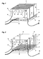
- la
figure 1 est une vue d'un établi de travail selon l'invention, le plan de travail étant dans sa position normale prévue pour les interventions sur les batteries ; et - la
figure 2 est une vue de cet établi après une descente du plan de travail. - Les
figures 1 et 2 présentent un caillebotis 2 formant un plan de travail isolé électriquement pour une tension de 500V, qui peut être notamment en polypropylène renforcé en-dessous par un cadre métallique pour obtenir l'isolation et la rigidité, ou en bois. Un grillage comportant des mailles de 5mm2 est fixé sous le caillebotis 2, pour récupérer des petites pièces qui tomberaient sur ce caillebotis sans les perdre en-dessous. - En particulier le caillebotis 2 peut être dimensionné pour supporter des batteries de dimension maximale de 950 par 1450mm, comportant une masse de 250kg, ce qui permet de répondre à la plupart des besoins des véhicules électriques et hybrides.
- Le caillebotis 2 est maintenu par quatre verrous 10 au niveau supérieur d'un bac à eau 4 de forme parallélépipédique, isolé électriquement, qui est posé sur un socle 6 comportant deux passages latéraux 8 permettant l'insertion des bras d'un chariot élévateur pour assurer un déplacement de l'ensemble du poste de travail.
- Le socle 6 comportant une structure métallique prévue pour supporter une masse de 1000kg, donne de la rigidité au bac à eau 4. Ce socle 6 dispose de quatre crochets non représentés, permettant un levage de l'ensemble.
- Le bac à eau 4 peut être avantageusement réalisé de manière économique en polypropylène, matière qui conserve ses caractéristiques mécaniques jusqu'à une température de 80°C. Le bac à eau 4 comporte aussi quatre crochets de levage non représentés, qui permettent de le soulever à vide pour le sortir de son socle 6.
- Le bac à eau 4 comporte une vanne manuelle d'entrée et de sortie de l'eau 20, reliée par une canalisation extérieure à une alimentation ou à un égout, qui permet le remplissage ou la vidange de ce bac. Une sonde de température plongée dans l'eau du bac 4 mesure la température de cette eau, qui est indiquée sur un affichage en façade 22.
- Le plan de travail formé par la surface du caillebotis 2 est avantageusement disposé à une hauteur de 950mm, qui permet à un opérateur d'intervenir facilement et de manière ergonomique sur une batterie posée dessus.
- Un espace intermédiaire 14 entre le socle 6 et le bac à eau 4 reçoit un mécanisme d'actionnement pneumatique, alimenté à une pression de 6 bars minimum par une canalisation extérieure reliée à une entrée 16 comportant un manomètre indiquant la pression du circuit d'alimentation.
- Le poste de travail comporte après l'entrée 16 un clapet anti-retour maintenant la pression d'air à l'intérieur, puis un accumulateur de pression permettant en cas de coupure de l'alimentation extérieure, de stocker 25 litres d'air à une pression minimale de 5 bars pendant au moins 8 heures.
- Le mécanisme d'actionnement comporte des vérins pneumatiques agissants sur des câbles 18, qui permettent à partir d'une commande de descente d'ouvrir les verrous 10 afin de descendre le caillebotis 2 en laissant filer les câbles de manière contrôlée, et à partir d'une commande de montée de tirer sur ces câbles pour remonter ce caillebotis.
- Un pupitre de commande 32 sur la façade avant du bac à eau 4 comporte un indicateur de la pression d'air interne 24 dans le poste de travail, une commande de montée du caillebotis 26 et une commande de descente de ce caillebotis 28. Une commande déportée de descente 30 du caillebotis 2, permet de commander à distance la descente de ce caillebotis.
- Les commandes 26, 28, 30 sont reliées par des tuyaux à un distributeur d'air situé dans le pupitre 32, qui est lui-même relié par des tuyaux 12 aux quatre verrous 10, ce qui lui permet de piloter l'ouverture ou la fermeture de ces verrous en fonction de la commande.
- En variante la commande déportée 30 peut être reliée au poste de travail par un moyen de communication sans fil ni tuyau.
- Le fonctionnement du poste de travail est le suivant. Après la dépose de la batterie sur le caillebotis 2 par un moyen de manutention extérieur, l'opérateur peut travailler à une hauteur convenable sur cette batterie.
- Dans le cas où un échauffement anormal se déclare dans les cellules électrochimiques de la batterie, avec un risque d'incendie, ou dans le cas d'un départ d'incendie, l'opérateur devant le poste actionne la commande de descente 28 du pupitre 32, ou un opérateur éloigné actionne la commande déportée 30.
- En variante une commande automatique détectant de manière autonome par des capteurs un échauffement trop important de la batterie, ou un départ de feu, peut être installée pour commander de manière automatique la descente du caillebottis 2. On assure ainsi la sécurité même en l'absence de personnel sur place.
- La vitesse de descente du caillebottis 2 est contrôlée à vide comme en charge, par le mécanisme d'actionnement pneumatique qui laisse filer les câbles 18 à une vitesse maîtrisée afin d'obtenir une descente dans l'eau avec un temps inférieur à une minute.
- Grâce à la réserve d'air comprimé interne au poste de travail, on dispose ainsi de manière autonome d'une énergie pneumatique qui permet de réaliser même en cas de coupure de l'alimentation extérieure, une descente contrôlée de la batterie dans l'eau afin d'assurer la sécurité dans tous les cas.
- Le volume d'eau résidant dans le bac à eau 4 est prévu pour refroidir suffisamment les batteries comportant une masse importante qui a atteint une température élevée. En pratique on peut prévoir un volume d'eau d'environ 700litres. Le bac à eau 4 comporte sur le côté opposé au pupitre, un indicateur de niveau d'eau.
- Le mécanisme d'actionnement pneumatique assure aussi par ses vérins la remontée du caillebottis 2 après une action sur la commande de montée 26, ce qui permet de remettre facilement et sans effort le poste de travail dans sa configuration d'origine.
- On obtient ainsi un poste de travail ergonomique, disposant d'un encombrement réduit, qui permet d'assurer la sécurité pour le travail sur des batteries électrochimiques comportant des risques d'inflammation, en particulier des batteries au lithium-ion. On notera que l'environnement du poste de travail comprenant le local d'implantation, ne nécessite aucune adaptation particulière pour assurer cette sécurité.
- En variante l'eau dans le bac 4 peut être contenue dans une poche étanche disposée au fond de ce bac, qui est percée lors du déclenchement de la descente du caillebotis 2. Cette poche permet de conserver la réserve d'eau de manière séparée et protégée pendant toute la période d'inutilisation, ce qui évite de la polluer, et empêche son évaporation.
- On peut aussi en variante disposer des verrous 10 de maintien du caillebotis 2 qui sont actionnés manuellement par un opérateur pour commander la descente de ce caillebotis. La remontée du caillebotis 2 se fait alors aussi de manière manuelle. On obtient ainsi un poste de travail qui n'utilise pas de source d'énergie extérieure.
- La descente du caillebottis 2 peut alors être contrôlée par un dispositif de freinage entièrement mécanique, avec des butées élastiques, ou des vérins de fin de course disposés au fond du bac 4 pour son arrêt.
- Suivant une autre variante, la réserve d'énergie pneumatique est une bombonne d'air comprimé à usage unique. La durée de maintien de la réserve d'air à la pression de 6 bars est ainsi prolongée de plus d'un an. Le poste de travail peut s'utiliser de façon autonome, sans apport d'énergie pneumatique extérieure.
- En cas d'emballement thermique de la batterie, l'opérateur percute la bombonne pour libérer l'air dans le circuit pneumatique. Les commandes de descente 28, 30 permettent alors de descendre le caillebottis 2 au fond du bac.
- Un branchement à une source d'énergie extérieure permet par la suite de remonter le caillebottis 2 avec la commande 26. Pour remettre l'établi de travail dans son état initial de fonctionnement, il suffit ensuite de remplacer la bombonne utilisée par une bombonne neuve.
- Suivant une autre variante on peut utiliser un système de commande électromécanique à la place du système pneumatique, qui réalise les mêmes fonctions. Dans ce cas on peut aussi prévoir une réserve d'énergie électrique autonome dans le poste de travail, sous forme d'un accumulateur électrique, afin d'assurer la sécurité même en cas de coupure de l'alimentation extérieure.
Claims (10)
- Etabli de travail pour des batteries électrochimiques, comportant un plan de travail (2) isolé électriquement qui est prévu pour recevoir la batterie, caractérisé en ce qu'il comporte un bac à eau (4) disposé en dessous du plan de travail (2), et des moyens de descente de ce plan dans le bac.
- Etabli de travail selon la revendication 1, caractérisé en ce que les moyens de descente du plan de travail (2) dans le bac comportent un mécanisme d'actionnement motorisé.
- Etabli de travail selon la revendication 2, caractérisé en ce qu'il comporte une réserve d'énergie autonome permettant au moins une manoeuvre du mécanisme d'actionnement motorisé pour réaliser une descente du plan de travail (2), en cas d'absence d'alimentation extérieure d'énergie.
- Etabli de travail selon la revendication 2 ou 3, caractérisé en ce que la vitesse de descente du plan de travail (2) est contrôlée par le mécanisme d'actionnement motorisé.
- Etabli de travail selon l'une quelconque des revendications 2 à 4, caractérisé en ce que le mécanisme d'actionnement motorisé réalise aussi la remontée du plan de travail (2).
- Etabli de travail selon l'une quelconque des revendications précédentes, caractérisé en ce que le plan de travail (2) est maintenu à la hauteur de travail par des verrous (10).
- Etabli de travail selon l'une quelconque des revendications précédentes, caractérisé en ce qu'il comporte une commande déportée (30) de descente du plan de travail (2), permettant de commander à distance la descente de ce plan.
- Etabli de travail selon l'une quelconque des revendications précédentes, caractérisé en ce que le plan de travail est formé par un caillebotis (2) isolé électriquement.
- Etabli de travail selon la revendication 8, caractérisé en ce qu'il comporte un grillage fixé sous le caillebotis (2).
- Etabli de travail selon la revendication 8 ou 9, caractérisé en ce que le caillebotis (2) comporte une surface en matière plastique moulée, renforcée pas une structure métallique.
Applications Claiming Priority (1)
| Application Number | Priority Date | Filing Date | Title |
|---|---|---|---|
| FR1453089A FR3019484B1 (fr) | 2014-04-08 | 2014-04-08 | Etabli de travail pour des batteries electrochimiques, comportant un bac a eau dispose en-dessous |
Publications (2)
| Publication Number | Publication Date |
|---|---|
| EP2929987A1 true EP2929987A1 (fr) | 2015-10-14 |
| EP2929987B1 EP2929987B1 (fr) | 2017-03-01 |
Family
ID=50729721
Family Applications (1)
| Application Number | Title | Priority Date | Filing Date |
|---|---|---|---|
| EP15159384.5A Active EP2929987B1 (fr) | 2014-04-08 | 2015-03-17 | Etabli de travail pour des batteries electrochimiques, comportant un bac à eau disposé en-dessous |
Country Status (3)
| Country | Link |
|---|---|
| EP (1) | EP2929987B1 (fr) |
| ES (1) | ES2621263T3 (fr) |
| FR (1) | FR3019484B1 (fr) |
Cited By (2)
| Publication number | Priority date | Publication date | Assignee | Title |
|---|---|---|---|---|
| WO2024200953A1 (fr) | 2023-03-27 | 2024-10-03 | Be Energy | Poste de travail manuel sécurisé pour des opérations sur batterie électrochimique |
| IT202300010992A1 (it) * | 2023-05-30 | 2024-11-30 | Iveco Spa | Banco o carrello di supporto per la manutenzione di una batteria di propulsione veicolare |
Citations (2)
| Publication number | Priority date | Publication date | Assignee | Title |
|---|---|---|---|---|
| GB675002A (en) * | 1949-11-21 | 1952-07-02 | Keighley Lab Ltd | Improvements in and relating to apparatus for the treatment of materials or objects in liquid baths |
| US4119044A (en) * | 1977-01-17 | 1978-10-10 | Merlin J. Peterson | Tool caddy |
-
2014
- 2014-04-08 FR FR1453089A patent/FR3019484B1/fr not_active Expired - Fee Related
-
2015
- 2015-03-17 ES ES15159384.5T patent/ES2621263T3/es active Active
- 2015-03-17 EP EP15159384.5A patent/EP2929987B1/fr active Active
Patent Citations (2)
| Publication number | Priority date | Publication date | Assignee | Title |
|---|---|---|---|---|
| GB675002A (en) * | 1949-11-21 | 1952-07-02 | Keighley Lab Ltd | Improvements in and relating to apparatus for the treatment of materials or objects in liquid baths |
| US4119044A (en) * | 1977-01-17 | 1978-10-10 | Merlin J. Peterson | Tool caddy |
Cited By (4)
| Publication number | Priority date | Publication date | Assignee | Title |
|---|---|---|---|---|
| WO2024200953A1 (fr) | 2023-03-27 | 2024-10-03 | Be Energy | Poste de travail manuel sécurisé pour des opérations sur batterie électrochimique |
| FR3147430A1 (fr) * | 2023-03-27 | 2024-10-04 | Be Energy | Poste de travail manuel sécurisé pour des opérations sur batterie électrochimique |
| IT202300010992A1 (it) * | 2023-05-30 | 2024-11-30 | Iveco Spa | Banco o carrello di supporto per la manutenzione di una batteria di propulsione veicolare |
| EP4470724A1 (fr) * | 2023-05-30 | 2024-12-04 | Iveco S.P.A. | Établi ou chariot pour l'entretien d'une batterie de propulsion de véhicule |
Also Published As
| Publication number | Publication date |
|---|---|
| EP2929987B1 (fr) | 2017-03-01 |
| ES2621263T3 (es) | 2017-07-03 |
| FR3019484B1 (fr) | 2016-04-01 |
| FR3019484A1 (fr) | 2015-10-09 |
Similar Documents
| Publication | Publication Date | Title |
|---|---|---|
| DE102019127014B4 (de) | Wannenförmiger Behälter zur Aufnahme von HV-Batterien und/oder E-Fahrzeugen und Verfahren zu dessen Betrieb | |
| EP3709386A1 (fr) | Dispositif de stockage de bloc-piles et procédé de commande associé | |
| FR3111129A3 (fr) | Conteneur de stockage pour batteries | |
| EP2929987B1 (fr) | Etabli de travail pour des batteries electrochimiques, comportant un bac à eau disposé en-dessous | |
| CN107658512A (zh) | 一种灌液式消防的电池模组仓储与充放电箱体系统 | |
| CN117108915A (zh) | 一种变电站sf6气体智能化运输补充设备及补充方法 | |
| EP2117995B1 (fr) | Installation souterraine de stockage d'huile alimentaire | |
| EP2997588B1 (fr) | Sectionneur pour source d'alimentation electrique continue de puissance | |
| EP3270035A1 (fr) | Dispositif de fourniture de gaz | |
| EP3232492B1 (fr) | Dispositif de protection multiple pour une batterie à cellule(s) de stockage | |
| FR2912875A1 (fr) | "dispositif de desherbage thermique" | |
| EP3558746A1 (fr) | Procédé et système de gestion d'un véhicule électrique ou hybride rechargeable | |
| CN210543010U (zh) | 一种微型消防车 | |
| JP2017086398A (ja) | 移動式粉末消火設備 | |
| FR3144974A1 (fr) | Source d’énergie pour systeme de gonflage (batterie thermique) | |
| CN217697708U (zh) | 一种具有自动消防功能的电池充电装置 | |
| EP0883222B1 (fr) | Déclencheur d'auto-protection pour transformateur électrique immergé | |
| FR3145517A1 (fr) | Systeme de batterie de traction de vehicule avec entree dans le caisson de fluide d’extinction d’incendie | |
| FR2857632A1 (fr) | Vehicule automobile avec reservoir de combustible gazeux et circuit d'alimentation basse pression | |
| KR102847042B1 (ko) | 전기차 화재 진압 자율 소방로봇 | |
| FR1280732A (fr) | Appareil de stérilisation rapide à automation intégrale | |
| FR3108038A1 (fr) | Installation de désinfection | |
| EP2958639B1 (fr) | Installation de lutte contre les incendies, incluant un réseau de sprinklers sous vide, susceptibles d'être déclenchés par un actuateur comprenant un piston et étant piloté par un actionneur maître | |
| WO2019096792A1 (fr) | Systeme de generation d'energie electrique nomade pour un aeronef comprenant une pile a combustible | |
| FR3080369A1 (fr) | Ensemble de stockage et de distribution de produits fluides |
Legal Events
| Date | Code | Title | Description |
|---|---|---|---|
| PUAI | Public reference made under article 153(3) epc to a published international application that has entered the european phase |
Free format text: ORIGINAL CODE: 0009012 |
|
| AK | Designated contracting states |
Kind code of ref document: A1 Designated state(s): AL AT BE BG CH CY CZ DE DK EE ES FI FR GB GR HR HU IE IS IT LI LT LU LV MC MK MT NL NO PL PT RO RS SE SI SK SM TR |
|
| AX | Request for extension of the european patent |
Extension state: BA ME |
|
| 17P | Request for examination filed |
Effective date: 20160321 |
|
| RBV | Designated contracting states (corrected) |
Designated state(s): AL AT BE BG CH CY CZ DE DK EE ES FI FR GB GR HR HU IE IS IT LI LT LU LV MC MK MT NL NO PL PT RO RS SE SI SK SM TR |
|
| RIN1 | Information on inventor provided before grant (corrected) |
Inventor name: ASTOUL, PHILIPPE Inventor name: POUJADE, CHRISTIAN Inventor name: SOUDEE,GUILLAME Inventor name: CHEAU, CHAKARA Inventor name: LEBEAU, JEROME |
|
| GRAP | Despatch of communication of intention to grant a patent |
Free format text: ORIGINAL CODE: EPIDOSNIGR1 |
|
| RIC1 | Information provided on ipc code assigned before grant |
Ipc: B25H 1/16 20060101AFI20160912BHEP |
|
| INTG | Intention to grant announced |
Effective date: 20160929 |
|
| RIN1 | Information on inventor provided before grant (corrected) |
Inventor name: ASTOUL, PHILIPPE Inventor name: LEBEAU, JEROME Inventor name: POUJADE, CHRISTIAN Inventor name: CHEAU, CHAKARA Inventor name: SOUDEE,GUILLAME |
|
| GRAS | Grant fee paid |
Free format text: ORIGINAL CODE: EPIDOSNIGR3 |
|
| GRAA | (expected) grant |
Free format text: ORIGINAL CODE: 0009210 |
|
| AK | Designated contracting states |
Kind code of ref document: B1 Designated state(s): AL AT BE BG CH CY CZ DE DK EE ES FI FR GB GR HR HU IE IS IT LI LT LU LV MC MK MT NL NO PL PT RO RS SE SI SK SM TR |
|
| REG | Reference to a national code |
Ref country code: GB Ref legal event code: FG4D Free format text: NOT ENGLISH |
|
| REG | Reference to a national code |
Ref country code: CH Ref legal event code: EP Ref country code: AT Ref legal event code: REF Ref document number: 870728 Country of ref document: AT Kind code of ref document: T Effective date: 20170315 |
|
| REG | Reference to a national code |
Ref country code: IE Ref legal event code: FG4D Free format text: LANGUAGE OF EP DOCUMENT: FRENCH Ref country code: FR Ref legal event code: PLFP Year of fee payment: 3 |
|
| REG | Reference to a national code |
Ref country code: DE Ref legal event code: R096 Ref document number: 602015001589 Country of ref document: DE |
|
| REG | Reference to a national code |
Ref country code: DE Ref legal event code: R084 Ref document number: 602015001589 Country of ref document: DE |
|
| REG | Reference to a national code |
Ref country code: ES Ref legal event code: FG2A Ref document number: 2621263 Country of ref document: ES Kind code of ref document: T3 Effective date: 20170703 |
|
| REG | Reference to a national code |
Ref country code: NL Ref legal event code: MP Effective date: 20170301 |
|
| REG | Reference to a national code |
Ref country code: LT Ref legal event code: MG4D |
|
| REG | Reference to a national code |
Ref country code: AT Ref legal event code: MK05 Ref document number: 870728 Country of ref document: AT Kind code of ref document: T Effective date: 20170301 |
|
| REG | Reference to a national code |
Ref country code: ES Ref legal event code: GC2A Effective date: 20170719 |
|
| REG | Reference to a national code |
Ref country code: GB Ref legal event code: 746 Effective date: 20170630 |
|
| PG25 | Lapsed in a contracting state [announced via postgrant information from national office to epo] |
Ref country code: FI Free format text: LAPSE BECAUSE OF FAILURE TO SUBMIT A TRANSLATION OF THE DESCRIPTION OR TO PAY THE FEE WITHIN THE PRESCRIBED TIME-LIMIT Effective date: 20170301 Ref country code: LT Free format text: LAPSE BECAUSE OF FAILURE TO SUBMIT A TRANSLATION OF THE DESCRIPTION OR TO PAY THE FEE WITHIN THE PRESCRIBED TIME-LIMIT Effective date: 20170301 Ref country code: GR Free format text: LAPSE BECAUSE OF FAILURE TO SUBMIT A TRANSLATION OF THE DESCRIPTION OR TO PAY THE FEE WITHIN THE PRESCRIBED TIME-LIMIT Effective date: 20170602 Ref country code: NO Free format text: LAPSE BECAUSE OF FAILURE TO SUBMIT A TRANSLATION OF THE DESCRIPTION OR TO PAY THE FEE WITHIN THE PRESCRIBED TIME-LIMIT Effective date: 20170601 Ref country code: HR Free format text: LAPSE BECAUSE OF FAILURE TO SUBMIT A TRANSLATION OF THE DESCRIPTION OR TO PAY THE FEE WITHIN THE PRESCRIBED TIME-LIMIT Effective date: 20170301 |
|
| RAP2 | Party data changed (patent owner data changed or rights of a patent transferred) |
Owner name: PSA AUTOMOBILES SA |
|
| PG25 | Lapsed in a contracting state [announced via postgrant information from national office to epo] |
Ref country code: LV Free format text: LAPSE BECAUSE OF FAILURE TO SUBMIT A TRANSLATION OF THE DESCRIPTION OR TO PAY THE FEE WITHIN THE PRESCRIBED TIME-LIMIT Effective date: 20170301 Ref country code: RS Free format text: LAPSE BECAUSE OF FAILURE TO SUBMIT A TRANSLATION OF THE DESCRIPTION OR TO PAY THE FEE WITHIN THE PRESCRIBED TIME-LIMIT Effective date: 20170301 Ref country code: AT Free format text: LAPSE BECAUSE OF FAILURE TO SUBMIT A TRANSLATION OF THE DESCRIPTION OR TO PAY THE FEE WITHIN THE PRESCRIBED TIME-LIMIT Effective date: 20170301 Ref country code: BG Free format text: LAPSE BECAUSE OF FAILURE TO SUBMIT A TRANSLATION OF THE DESCRIPTION OR TO PAY THE FEE WITHIN THE PRESCRIBED TIME-LIMIT Effective date: 20170601 Ref country code: SE Free format text: LAPSE BECAUSE OF FAILURE TO SUBMIT A TRANSLATION OF THE DESCRIPTION OR TO PAY THE FEE WITHIN THE PRESCRIBED TIME-LIMIT Effective date: 20170301 |
|
| PG25 | Lapsed in a contracting state [announced via postgrant information from national office to epo] |
Ref country code: NL Free format text: LAPSE BECAUSE OF FAILURE TO SUBMIT A TRANSLATION OF THE DESCRIPTION OR TO PAY THE FEE WITHIN THE PRESCRIBED TIME-LIMIT Effective date: 20170301 |
|
| PG25 | Lapsed in a contracting state [announced via postgrant information from national office to epo] |
Ref country code: SK Free format text: LAPSE BECAUSE OF FAILURE TO SUBMIT A TRANSLATION OF THE DESCRIPTION OR TO PAY THE FEE WITHIN THE PRESCRIBED TIME-LIMIT Effective date: 20170301 Ref country code: RO Free format text: LAPSE BECAUSE OF FAILURE TO SUBMIT A TRANSLATION OF THE DESCRIPTION OR TO PAY THE FEE WITHIN THE PRESCRIBED TIME-LIMIT Effective date: 20170301 Ref country code: EE Free format text: LAPSE BECAUSE OF FAILURE TO SUBMIT A TRANSLATION OF THE DESCRIPTION OR TO PAY THE FEE WITHIN THE PRESCRIBED TIME-LIMIT Effective date: 20170301 Ref country code: CZ Free format text: LAPSE BECAUSE OF FAILURE TO SUBMIT A TRANSLATION OF THE DESCRIPTION OR TO PAY THE FEE WITHIN THE PRESCRIBED TIME-LIMIT Effective date: 20170301 |
|
| PG25 | Lapsed in a contracting state [announced via postgrant information from national office to epo] |
Ref country code: PL Free format text: LAPSE BECAUSE OF FAILURE TO SUBMIT A TRANSLATION OF THE DESCRIPTION OR TO PAY THE FEE WITHIN THE PRESCRIBED TIME-LIMIT Effective date: 20170301 Ref country code: PT Free format text: LAPSE BECAUSE OF FAILURE TO SUBMIT A TRANSLATION OF THE DESCRIPTION OR TO PAY THE FEE WITHIN THE PRESCRIBED TIME-LIMIT Effective date: 20170703 Ref country code: IS Free format text: LAPSE BECAUSE OF FAILURE TO SUBMIT A TRANSLATION OF THE DESCRIPTION OR TO PAY THE FEE WITHIN THE PRESCRIBED TIME-LIMIT Effective date: 20170701 Ref country code: SM Free format text: LAPSE BECAUSE OF FAILURE TO SUBMIT A TRANSLATION OF THE DESCRIPTION OR TO PAY THE FEE WITHIN THE PRESCRIBED TIME-LIMIT Effective date: 20170301 |
|
| REG | Reference to a national code |
Ref country code: DE Ref legal event code: R097 Ref document number: 602015001589 Country of ref document: DE |
|
| REG | Reference to a national code |
Ref country code: IE Ref legal event code: MM4A |
|
| PLBE | No opposition filed within time limit |
Free format text: ORIGINAL CODE: 0009261 |
|
| STAA | Information on the status of an ep patent application or granted ep patent |
Free format text: STATUS: NO OPPOSITION FILED WITHIN TIME LIMIT |
|
| PG25 | Lapsed in a contracting state [announced via postgrant information from national office to epo] |
Ref country code: MC Free format text: LAPSE BECAUSE OF FAILURE TO SUBMIT A TRANSLATION OF THE DESCRIPTION OR TO PAY THE FEE WITHIN THE PRESCRIBED TIME-LIMIT Effective date: 20170301 Ref country code: LU Free format text: LAPSE BECAUSE OF NON-PAYMENT OF DUE FEES Effective date: 20170317 Ref country code: DK Free format text: LAPSE BECAUSE OF FAILURE TO SUBMIT A TRANSLATION OF THE DESCRIPTION OR TO PAY THE FEE WITHIN THE PRESCRIBED TIME-LIMIT Effective date: 20170301 |
|
| 26N | No opposition filed |
Effective date: 20171204 |
|
| REG | Reference to a national code |
Ref country code: FR Ref legal event code: PLFP Year of fee payment: 4 |
|
| PG25 | Lapsed in a contracting state [announced via postgrant information from national office to epo] |
Ref country code: IE Free format text: LAPSE BECAUSE OF NON-PAYMENT OF DUE FEES Effective date: 20170317 Ref country code: SI Free format text: LAPSE BECAUSE OF FAILURE TO SUBMIT A TRANSLATION OF THE DESCRIPTION OR TO PAY THE FEE WITHIN THE PRESCRIBED TIME-LIMIT Effective date: 20170301 |
|
| REG | Reference to a national code |
Ref country code: BE Ref legal event code: MM Effective date: 20170331 |
|
| PG25 | Lapsed in a contracting state [announced via postgrant information from national office to epo] |
Ref country code: BE Free format text: LAPSE BECAUSE OF NON-PAYMENT OF DUE FEES Effective date: 20170331 |
|
| REG | Reference to a national code |
Ref country code: FR Ref legal event code: CA Effective date: 20180312 Ref country code: FR Ref legal event code: CD Owner name: PEUGEOT CITROEN AUTOMOBILES SA, FR Effective date: 20180312 |
|
| PG25 | Lapsed in a contracting state [announced via postgrant information from national office to epo] |
Ref country code: MT Free format text: LAPSE BECAUSE OF FAILURE TO SUBMIT A TRANSLATION OF THE DESCRIPTION OR TO PAY THE FEE WITHIN THE PRESCRIBED TIME-LIMIT Effective date: 20170301 |
|
| REG | Reference to a national code |
Ref country code: CH Ref legal event code: PL |
|
| PG25 | Lapsed in a contracting state [announced via postgrant information from national office to epo] |
Ref country code: LI Free format text: LAPSE BECAUSE OF NON-PAYMENT OF DUE FEES Effective date: 20180331 Ref country code: CH Free format text: LAPSE BECAUSE OF NON-PAYMENT OF DUE FEES Effective date: 20180331 |
|
| PG25 | Lapsed in a contracting state [announced via postgrant information from national office to epo] |
Ref country code: HU Free format text: LAPSE BECAUSE OF FAILURE TO SUBMIT A TRANSLATION OF THE DESCRIPTION OR TO PAY THE FEE WITHIN THE PRESCRIBED TIME-LIMIT; INVALID AB INITIO Effective date: 20150317 |
|
| PG25 | Lapsed in a contracting state [announced via postgrant information from national office to epo] |
Ref country code: CY Free format text: LAPSE BECAUSE OF FAILURE TO SUBMIT A TRANSLATION OF THE DESCRIPTION OR TO PAY THE FEE WITHIN THE PRESCRIBED TIME-LIMIT Effective date: 20170301 |
|
| PG25 | Lapsed in a contracting state [announced via postgrant information from national office to epo] |
Ref country code: MK Free format text: LAPSE BECAUSE OF FAILURE TO SUBMIT A TRANSLATION OF THE DESCRIPTION OR TO PAY THE FEE WITHIN THE PRESCRIBED TIME-LIMIT Effective date: 20170301 |
|
| PG25 | Lapsed in a contracting state [announced via postgrant information from national office to epo] |
Ref country code: TR Free format text: LAPSE BECAUSE OF FAILURE TO SUBMIT A TRANSLATION OF THE DESCRIPTION OR TO PAY THE FEE WITHIN THE PRESCRIBED TIME-LIMIT Effective date: 20170301 |
|
| PG25 | Lapsed in a contracting state [announced via postgrant information from national office to epo] |
Ref country code: AL Free format text: LAPSE BECAUSE OF FAILURE TO SUBMIT A TRANSLATION OF THE DESCRIPTION OR TO PAY THE FEE WITHIN THE PRESCRIBED TIME-LIMIT Effective date: 20170301 |
|
| PGFP | Annual fee paid to national office [announced via postgrant information from national office to epo] |
Ref country code: GB Payment date: 20260219 Year of fee payment: 12 |
|
| PGFP | Annual fee paid to national office [announced via postgrant information from national office to epo] |
Ref country code: DE Payment date: 20260219 Year of fee payment: 12 |
|
| PGFP | Annual fee paid to national office [announced via postgrant information from national office to epo] |
Ref country code: IT Payment date: 20260219 Year of fee payment: 12 |
|
| PGFP | Annual fee paid to national office [announced via postgrant information from national office to epo] |
Ref country code: FR Payment date: 20260219 Year of fee payment: 12 |
|
| PGFP | Annual fee paid to national office [announced via postgrant information from national office to epo] |
Ref country code: ES Payment date: 20260401 Year of fee payment: 12 |