EP2929901A1 - Spritze mit Deaktivierungsmechanismus - Google Patents
Spritze mit Deaktivierungsmechanismus Download PDFInfo
- Publication number
- EP2929901A1 EP2929901A1 EP15155440.9A EP15155440A EP2929901A1 EP 2929901 A1 EP2929901 A1 EP 2929901A1 EP 15155440 A EP15155440 A EP 15155440A EP 2929901 A1 EP2929901 A1 EP 2929901A1
- Authority
- EP
- European Patent Office
- Prior art keywords
- stopper
- plunger rod
- barrel
- syringe assembly
- thumb press
- Prior art date
- Legal status (The legal status is an assumption and is not a legal conclusion. Google has not performed a legal analysis and makes no representation as to the accuracy of the status listed.)
- Granted
Links
- 230000007246 mechanism Effects 0.000 title description 2
- 210000003813 thumb Anatomy 0.000 claims abstract description 71
- 230000000007 visual effect Effects 0.000 claims abstract description 51
- 239000003550 marker Substances 0.000 claims description 38
- 230000002093 peripheral effect Effects 0.000 claims description 26
- 239000012530 fluid Substances 0.000 claims description 12
- 230000007704 transition Effects 0.000 claims description 6
- 230000007423 decrease Effects 0.000 claims description 4
- 238000004891 communication Methods 0.000 claims description 2
- 238000001514 detection method Methods 0.000 claims 1
- 238000002347 injection Methods 0.000 abstract description 15
- 239000007924 injection Substances 0.000 abstract description 15
- 230000000712 assembly Effects 0.000 abstract description 7
- 238000000429 assembly Methods 0.000 abstract description 7
- 239000000463 material Substances 0.000 description 8
- 239000003814 drug Substances 0.000 description 6
- 229940079593 drug Drugs 0.000 description 5
- 239000004033 plastic Substances 0.000 description 5
- 230000002829 reductive effect Effects 0.000 description 3
- 208000031872 Body Remains Diseases 0.000 description 2
- 238000010276 construction Methods 0.000 description 2
- 230000003247 decreasing effect Effects 0.000 description 2
- 201000010099 disease Diseases 0.000 description 2
- 208000037265 diseases, disorders, signs and symptoms Diseases 0.000 description 2
- 238000007373 indentation Methods 0.000 description 2
- 238000005259 measurement Methods 0.000 description 2
- 238000000034 method Methods 0.000 description 2
- 238000012986 modification Methods 0.000 description 2
- 230000004048 modification Effects 0.000 description 2
- 229920003052 natural elastomer Polymers 0.000 description 2
- 229920001194 natural rubber Polymers 0.000 description 2
- 230000001681 protective effect Effects 0.000 description 2
- 239000000243 solution Substances 0.000 description 2
- 230000001954 sterilising effect Effects 0.000 description 2
- 238000004659 sterilization and disinfection Methods 0.000 description 2
- 229920003051 synthetic elastomer Polymers 0.000 description 2
- 239000005061 synthetic rubber Substances 0.000 description 2
- 238000012546 transfer Methods 0.000 description 2
- 206010013654 Drug abuse Diseases 0.000 description 1
- 241000725303 Human immunodeficiency virus Species 0.000 description 1
- 241000700605 Viruses Species 0.000 description 1
- 230000004913 activation Effects 0.000 description 1
- 230000008901 benefit Effects 0.000 description 1
- 238000011109 contamination Methods 0.000 description 1
- 239000011521 glass Substances 0.000 description 1
- 208000006454 hepatitis Diseases 0.000 description 1
- 231100000283 hepatitis Toxicity 0.000 description 1
- 238000001990 intravenous administration Methods 0.000 description 1
- 230000009467 reduction Effects 0.000 description 1
- 230000000452 restraining effect Effects 0.000 description 1
- 230000000717 retained effect Effects 0.000 description 1
- 239000007787 solid Substances 0.000 description 1
- 208000011117 substance-related disease Diseases 0.000 description 1
Images


Classifications
-
- A—HUMAN NECESSITIES
- A61—MEDICAL OR VETERINARY SCIENCE; HYGIENE
- A61M—DEVICES FOR INTRODUCING MEDIA INTO, OR ONTO, THE BODY; DEVICES FOR TRANSDUCING BODY MEDIA OR FOR TAKING MEDIA FROM THE BODY; DEVICES FOR PRODUCING OR ENDING SLEEP OR STUPOR
- A61M5/00—Devices for bringing media into the body in a subcutaneous, intra-vascular or intramuscular way; Accessories therefor, e.g. filling or cleaning devices, arm-rests
- A61M5/50—Devices for bringing media into the body in a subcutaneous, intra-vascular or intramuscular way; Accessories therefor, e.g. filling or cleaning devices, arm-rests having means for preventing re-use, or for indicating if defective, used, tampered with or unsterile
- A61M5/5066—Means for preventing re-use by disconnection of piston and piston-rod
-
- A—HUMAN NECESSITIES
- A61—MEDICAL OR VETERINARY SCIENCE; HYGIENE
- A61M—DEVICES FOR INTRODUCING MEDIA INTO, OR ONTO, THE BODY; DEVICES FOR TRANSDUCING BODY MEDIA OR FOR TAKING MEDIA FROM THE BODY; DEVICES FOR PRODUCING OR ENDING SLEEP OR STUPOR
- A61M5/00—Devices for bringing media into the body in a subcutaneous, intra-vascular or intramuscular way; Accessories therefor, e.g. filling or cleaning devices, arm-rests
- A61M5/50—Devices for bringing media into the body in a subcutaneous, intra-vascular or intramuscular way; Accessories therefor, e.g. filling or cleaning devices, arm-rests having means for preventing re-use, or for indicating if defective, used, tampered with or unsterile
- A61M5/5013—Means for blocking the piston or the fluid passageway to prevent illegal refilling of a syringe
- A61M5/502—Means for blocking the piston or the fluid passageway to prevent illegal refilling of a syringe for blocking the piston
-
- A—HUMAN NECESSITIES
- A61—MEDICAL OR VETERINARY SCIENCE; HYGIENE
- A61M—DEVICES FOR INTRODUCING MEDIA INTO, OR ONTO, THE BODY; DEVICES FOR TRANSDUCING BODY MEDIA OR FOR TAKING MEDIA FROM THE BODY; DEVICES FOR PRODUCING OR ENDING SLEEP OR STUPOR
- A61M5/00—Devices for bringing media into the body in a subcutaneous, intra-vascular or intramuscular way; Accessories therefor, e.g. filling or cleaning devices, arm-rests
- A61M5/178—Syringes
- A61M5/31—Details
- A61M5/315—Pistons; Piston-rods; Guiding, blocking or restricting the movement of the rod or piston; Appliances on the rod for facilitating dosing ; Dosing mechanisms
- A61M5/31511—Piston or piston-rod constructions, e.g. connection of piston with piston-rod
- A61M2005/31516—Piston or piston-rod constructions, e.g. connection of piston with piston-rod reducing dead-space in the syringe barrel after delivery
-
- A—HUMAN NECESSITIES
- A61—MEDICAL OR VETERINARY SCIENCE; HYGIENE
- A61M—DEVICES FOR INTRODUCING MEDIA INTO, OR ONTO, THE BODY; DEVICES FOR TRANSDUCING BODY MEDIA OR FOR TAKING MEDIA FROM THE BODY; DEVICES FOR PRODUCING OR ENDING SLEEP OR STUPOR
- A61M5/00—Devices for bringing media into the body in a subcutaneous, intra-vascular or intramuscular way; Accessories therefor, e.g. filling or cleaning devices, arm-rests
- A61M5/50—Devices for bringing media into the body in a subcutaneous, intra-vascular or intramuscular way; Accessories therefor, e.g. filling or cleaning devices, arm-rests having means for preventing re-use, or for indicating if defective, used, tampered with or unsterile
- A61M5/5013—Means for blocking the piston or the fluid passageway to prevent illegal refilling of a syringe
- A61M5/502—Means for blocking the piston or the fluid passageway to prevent illegal refilling of a syringe for blocking the piston
- A61M2005/5026—Means for blocking the piston or the fluid passageway to prevent illegal refilling of a syringe for blocking the piston allowing single filling of syringe
-
- A—HUMAN NECESSITIES
- A61—MEDICAL OR VETERINARY SCIENCE; HYGIENE
- A61M—DEVICES FOR INTRODUCING MEDIA INTO, OR ONTO, THE BODY; DEVICES FOR TRANSDUCING BODY MEDIA OR FOR TAKING MEDIA FROM THE BODY; DEVICES FOR PRODUCING OR ENDING SLEEP OR STUPOR
- A61M5/00—Devices for bringing media into the body in a subcutaneous, intra-vascular or intramuscular way; Accessories therefor, e.g. filling or cleaning devices, arm-rests
- A61M5/50—Devices for bringing media into the body in a subcutaneous, intra-vascular or intramuscular way; Accessories therefor, e.g. filling or cleaning devices, arm-rests having means for preventing re-use, or for indicating if defective, used, tampered with or unsterile
- A61M5/5066—Means for preventing re-use by disconnection of piston and piston-rod
- A61M2005/5073—Means for preventing re-use by disconnection of piston and piston-rod by breaking or rupturing the connection parts
Definitions
- the present invention relates to syringe assemblies having a passive disabling mechanism which restricts removal of the plunger rod after injection to prevent reuse, syringe assemblies wherein the stopper and plunger rod operate using relative motion to passively disable the syringe, syringe assemblies including a removeably connected stopper and plunger rod to prevent disassembly of the syringe prior to use and syringe assemblies including visual indication or markings to indicate use of the syringe or a disabled syringe.
- hypodermic syringe products without sterilization or sufficient sterilization is believed to perpetuate drug abuse and facilitate the transfer of contagious diseases.
- the reuse of syringes by intravenous drug users further exacerbates the transfer of contagious diseases because they comprise a high-risk group with respect to certain viruses such as the AIDS virus and hepatitis.
- a high risk of contamination also exists in countries with shortages of medical personnel and supplies.
- a syringe which can be rendered inoperable after use presents a viable solution to these issues.
- Various syringes have been proposed and are commercially available that can be disabled by the user by taking active steps to disable the syringe.
- Single-use syringes that do not require the user to actively disable the syringe are also thought to offer a solution. It would be desirable to provide syringes that are automatically or passively disabled from reuse and can be manufactured in a cost-effective manner by, for example, utilizing fewer parts. Further, markings or other indicators which visually indicate whether a syringe has been used or is disabled would also be desirable.
- the present invention provides a passive disabling system for a syringe assembly, which activates after completion of an injection cycle.
- a syringe assembly incorporates a stopper and plunger rod attached in a manner to prevent users from disassembling the syringe prior to completion of the injection cycle. Accordingly, a means for preventing removal of a plunger rod from a syringe assembly is provided. A user of such a syringe can fill, inject and/or reconstitute medication.
- the distal end of the device is the end closest to a patient and the proximal end of the device is the end away from the patient and closest to a practitioner.
- a syringe assembly which includes a barrel, an elongate plunger rod with a thumb press and stopper having respective structures and assembly which allow the user to passively restrict access or removal of the plunger rod from the barrel to prevent reuse of the syringe assembly.
- the barrel includes a distal end, an open proximal end, a cylindrical sidewall, which defines a chamber in which fluid may be held, and a distal wall. An opening in the distal wall permits fluid to flow from the chamber through the opening.
- the barrel may also include an annular extension or collar that extends from the proximal end of the barrel. The annular extension may have a diameter greater than the diameter of the plunger rod and the thumb press that is attached to the plunger rod.
- the annular extension provides a means for preventing removal of the plunger rod from the barrel after use.
- the barrel includes a marker or indicator which indicates whether the syringe has been disabled or the plunger has been locked within the barrel.
- the sidewall of the barrel has a continuous diameter or first inner diameter.
- the term "diameter” is a measurement of the longest distance between the walls of the barrel having any cross-sectional shape.
- conventional syringes are typically cylindrical with a circular cross-sectional shape.
- the barrel includes a rib, locking rib or other such impediment suitable for restricting the proximal movement of the plunger rod, adjacent to its proximal end.
- Embodiments of the present invention also include an extended plunger rod which has a proximal end, a distal end, and a main body between the proximal and distal end.
- the plunger rod slides or otherwise moves proximally and distally within the chamber of the barrel.
- a thumb press is attached to the proximal end of the plunger.
- the thumb press includes a proximal end and a distal end and, in one or more embodiments, includes a diameter which can vary from the distal end to the proximal end. In a specific embodiment, the diameter of the thumb press decreases from the distal end to the proximal end.
- the distal end of the plunger includes a stopper-engaging portion having a distal and proximal end.
- the stopper-engaging portion of such embodiments provides a means for the stopper and plunger rod to move proximally and distally within the barrel.
- the stopper-engaging portion allows the stopper and plunger rod to move proximally and distally relative to each other.
- the stopper may move a pre-selected axial distance relative to the stopper-engaging portion of the plunger rod.
- the stopper-engaging portion may include a rim at its distal end, a retainer or alternate means suitable for restraining the stopper.
- the stopper-engaging portion according to one or more embodiments may also include a visual indicator or a visual display that indicates use of the syringe or whether the syringe is disabled.
- the stopper and the plunger rod are connected such that they move distally and proximally within the barrel in a fixed relationship.
- the stopper and plunger rod move distally within the plunger until the stopper reaches the distal wall and the thumb press moves within the barrel and/or the annular extension.
- the plunger rod further includes a means for locking the plunger rod in the barrel to prevent reuse of the syringe assembly when the syringe is fully injected or "bottomed.”
- the means can have an outer diameter greater than the inner diameter of the barrel at the rib or the second inner diameter.
- bottomed shall refer to the position of the syringe assembly wherein the stopper, while attached to the plunger rod, is in contact with the distal wall of the barrel and the plunger rod can no longer move in the distal direction.
- One or more embodiments of the present invention utilize a protrusion, or annular protrusion that extends radially from the plunger rod.
- the protrusion is located between the thumb press and the main body, as an example of a means for locking the plunger rod in the barrel.
- the protrusion is integrally molded to the plunger rod.
- the protrusion can have an outer diameter greater than the second inner diameter. In this specific configuration, once the protrusion distally moves past the rib and into the barrel, it becomes locked by the rib, thereby preventing proximal movement of the plunger rod.
- the protrusion can be tapered or otherwise shaped in such a manner such that it may move in the distal direction past the rib more easily.
- the stopper has a proximal end and a distal end, and the stopper is attached the stopper-engaging portion of the plunger rod.
- the stopper may further comprise a stopper body or stopper boss at the proximal end of the stopper.
- a peripheral lip may be included at the proximal end of the stopper body.
- a frangible connection may be provided to connect the stopper to the plunger rod, which may connect the stopper and the peripheral lip.
- the stopper-engaging portion of the plunger rod and the stopper may be connected in a manner such that when the user applies a force in the proximal direction for aspiration or filling the syringe, the stopper remains stationary until plunger rod moves in the proximal direction the length of the pre-selected axial distance.
- the stopper begins to move in the proximal direction in tandem with the plunger rod, after the plunger rod has traveled the pre-selected axial distance in the proximal direction.
- An optional visual indicator or display disposed on the stopper-engaging portion of the plunger rod is visible when the user fills the syringe assembly.
- the attachment of the stopper and the stopper-engaging portion allows the plunger rod to move distally for a length of the pre-selected axial distance, while the stopper remains stationary. After the plunger rod travels distally for the length of the pre-selected axial distance, the stopper begins to move distally with the plunger rod. During such distal movement, where a visual indicator or display is utilized, the visual indicator or display disposed on the stopper-engaging portion of the plunger rod is no longer visible.
- the visual marker disposed on the barrel continues to be visible, even after the plunger rod is locked.
- the marker provides an alternative means of indicating the syringe has been disabled.
- the plunger rod may optionally include a visual alignment marker which moves from being proximally adjacent to the visual marker to being distally adjacent to the visual marker when the syringe assembly is disabled.
- the visual alignment marker can include the protrusion.
- the total length of the plunger rod is decreased by pre-selected axial distance when the stopper and plunger rod move together in the distal direction during injection of the contents of the syringe assembly.
- the stopper and stopper-engaging portion of the syringe assembly are attached in a manner such that when a user has fully completed the injection cycle and the stopper is in contact with the distal wall of the barrel, the thumb press moves distally into or nestably engages with the annular extension or collar at the proximal end of the barrel.
- the annular extension or collar is configured to partially envelope a portion of the thumb press, thereby preventing the user from accessing the thumb press and pulling the plunger rod out of the barrel.
- the annular extension or collar is shaped to provide a nesting area for the thumb press or to fully envelope the thumb press when the stopper is in contact with the distal wall of the barrel.
- the annular extension and thumb press include locking features, such as a detent and cooperating tab or retaining ring, which are configured to lock the thumb press at the proximal end of the barrel when the thumb press moves distally into the annular extension.
- the distal movement of the stopper and plunger rod allows the protrusion to move past the rib into the locked position.
- the relative movement of the stopper and the stopper-engaging portion also allows the protrusion to move distally past the rib into the locked position, when the syringe assembly is bottomed.
- the protrusion advances past the rib of the barrel, it locks the plunger rod within the barrel and prevents the user from reusing the syringe assembly or otherwise pulling the plunger rod out of the barrel.
- the optional visual indicator or display on the stopper-engaging portion of the plunger rod is no longer visible, indicating the syringe has been disabled.
- the visual marker remains visible and indicates when the plunger rod has been locked within the barrel.
- the syringe assembly may include one or more frangible portions of the plunger rod, which break when a user attempts to move the plunger rod in a proximal direction after the protrusion has advanced past the rib of the barrel.
- Other suitable means may be utilized for separating a portion of the plunger rod from the main body when the user applies sufficient proximal force to the plunger rod or otherwise attempts to reuse the syringe assembly after it is bottomed.
- the stopper and the stopper-engaging portion are attached in such a manner such that when a user attempts to disassemble the syringe assembly prior to aspiration, injection or bottoming, the stopper-engaging portion disengages from the stopper, leaving the stopper inside the barrel and allowing the separated plunger rod to be removed.
- inner diameter of the barrel at the rib, or the second inner diameter is less than the outer diameter of the stopper, and thereby prevents the stopper from moving proximally past the rib and causes the stopper-engaging portion to detach from the stopper, leaving the stopper inside the barrel.
- An optional frangible connection of the stopper breaks when a user attempts to disassemble the syringe assembly by applying a continuous force in the proximal direction to the plunger rod prior to aspiration, injection or bottoming.
- One aspect of the present invention provides for a syringe assembly including a barrel, plunger rod and stopper having individual features and construction which allow the user to passively lock the plunger rod within the barrel to prevent reuse of the syringe assembly.
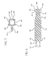
- Fig. 1 shows a syringe assembly 100 according to one or more embodiments.
- the syringe assembly includes a barrel 120, a plunger rod 140 and a stopper 160, arranged such that the proximal end 169 of stopper is attached to the distal end 141 of the plunger rod.
- the connected stopper 160 and plunger rod 140 are inserted into the proximal end 129 of the barrel 120.
- the barrel 120 has a cylindrical sidewall 110 with an interior surface 126 that defines a chamber 128.
- the chamber 128 holds the contents of the syringe assembly which may include medication in powdered or fluid form.
- the barrel 120 is shown as having an open proximal end 129, a distal end 121, and a distal wall 122.
- the distal wall 122 has an opening 111 in fluid communication with the chamber 128.
- the sidewall 110 of the barrel 120 defines a chamber having a continuous inner diameter along the longitudinal axis of the syringe.
- the barrel can include a sidewall has an inner diameter, which decreases linearly from the proximal end to the distal end.
- the configuration shown is merely exemplary, and the components can be different in shape and size than shown.
- the barrel can have an exterior prism shape, while retaining a cylindrical interior shape.
- both the exterior and interior surfaces of the barrel can have non-circular cross-sectional shapes.
- the syringe barrel 120 is shown as having a peripheral flange 124 attached at the proximal end 129 of the barrel 120.
- the barrel 120 further includes a needle cannula 150, having a lumen 153 attached to the opening 111 in the distal wall 122 of the barrel 120.
- attachment means 152 is provided for attaching the needle cannula 150 to the distal wall 122.
- the assembly 100 may also include a protective cap over the needle cannula (not shown).
- the proximal end of the barrel 129 includes an annular extension or collar 400.
- the annular extension 400 includes a proximal end 409 and a distal end 401.
- the annular extension 400 can have a diameter greater than the diameter of the thumb press 300 and, in one or more embodiments, the annular extension 400 can also have a length that would allow it to envelope or cover the thumb press 300 after a full injection cycle.
- the barrel 120 further includes a rib 123 adjacent its proximal end 129.
- the rib 123 is distally adjacent to the annular extension 400.
- the rib 123 can be formed on the interior wall of the annular extension (not shown), and, in such embodiments, to provide a means for locking the plunger rod disposed on the plunger rod such that it advances distally past the rib 123 when the stopper 160 is in contact with the distal wall 122 of the syringe.
- a plurality of ribs is disposed on the interior surface 126 of the barrel.
- one rib is distally adjacent to the annular extension and a second rib is formed on the interior wall of the annular extension.
- the inner diameter of the barrel at the location of the rib 123 is smaller than the inner diameter of the barrel 120 at other locations along the length of the barrel.
- one or more optional tabs or detents can be used to create a region of the barrel having a diameter smaller than the inner diameter of the barrel 120.
- the plunger rod can be retained in the barrel by such tabs that are co-radial with tabs or detents on the plunger rod.
- the rib can include a ring formed along entire circumference of the interior surface 126 or a portion of the interior surface 126 of the inner diameter of the barrel 120 (not shown).
- the barrel 120 also may include a diameter transition region proximally adjacent to the rib 123 (not shown). In such a configuration, the inner diameter of the barrel at the diameter transition region increases from the distal end 121 to the proximal end 129 of the barrel 120.
- the barrel may also include an increased diameter region proximally adjacent to the diameter transition region (not shown). In such a configuration, the increased diameter region has a greater inner diameter than the inner diameter of the barrel of the entire diameter transition region.
- the barrel may be made of plastic, glass or other suitable material.
- the barrel further includes optional dosage measurement indicia (not shown).
- the shown stopper 160 has a distal end 161, a proximal end 169, a stopper body 164 and a peripheral edge 162 which forms a seal with the interior surface 126 of the barrel.
- the peripheral edge 162 of the stopper 160 has a larger diameter than the diameter of the interior surface of the rib 123.
- the stopper 160 shown in Fig. 5 includes an optional elongate tip 166 on its distal end 161 to facilitate reduction of the residual fluid and expulsion of fluid from the syringe barrel.
- the stopper 160 is shown as further having a tapered portion 165 adjacent to the stopper body 164 at its proximal end 169.
- a neck 163 is adjacent to the tapered portion 165 at the proximal end 169 of the stopper 160.
- the stopper body 164 is shown as also including an interior recess 168, which allows the stopper 160 to connect to the plunger rod.
- the stopper is typically made of plastic or other easily disposable and/or recyclable material. It may be desirable to incorporate natural or synthetic rubber in the stopper or use a natural or synthetic rubber seal with the stopper. It will be understood that the stopper may incorporate multiple seals.
- the syringe assembly includes a plunger rod 140 having a proximal end 149, a distal end 141, and a main body 148 extending between the proximal end 149 and distal end 141.
- the distal end 141 of the plunger rod includes a stopper-engaging portion 146 which connects the stopper 160 to the plunger rod 140.
- a peripheral rim 147 may be provided to help retain the stopper 160 on the plunger rod 140.
- detents or tabs can be used to retain the stopper 160 on the plunger rod 140.
- the stopper-engaging portion 146 may also include one or more notches 142 at the distal end 141 of the plunger rod.
- the plunger rod 140 further includes a thumb press 300 at the proximal end 149 of the plunger rod 140.
- the thumb press 300 further includes a distal end 301, a proximal end 309 and contoured portion 310 between the distal end and the proximal end.
- the contoured portion 310 includes a segment of the thumb press having a diameter that decreases from the distal end 301 to the proximal end 309 of the thumb press.
- the proximal end of the thumb press 309 can have a flat surface or can be curved.
- the thumb press can be contoured to fit within the barrel after a full injection cycle.
- the thumb press can be contoured to at least partially nest or fit within the annular extension disposed at the proximal end of the barrel.
- the thumb press can includes a writeable surface and/or label.
- the plunger rod 140 further includes a protrusion 144 shown as a protrusion 144 between the thumb press 300 and the main body 148.
- the outer diameter of the plunger rod at the protrusion 144 is greater than the inner diameter of the barrel 120 at the rib 123.
- the protrusion 144 includes a tapered portion that facilitates distal movement of the protrusion past the rib 123 and into the barrel 120, as will become apparent in the subsequent discussion of operation of the syringe.
- the syringe assembly is configured to allow the protrusion 144 to advance distally past the rib 123, to lock the plunger rod in the barrel when the user bottoms out the plunger rod in the barrel (as more clearly shown in Figs. 10 and 11 ).
- the plunger rod 140 may also include a disc 145 disposed at the distal end 141 of the plunger rod. In one embodiment, the disc 145 is the means for locking the plunger rod within the barrel.
- the stopper 160 is permitted to move distally and proximally within the barrel when connected to the stopper-engaging portion 146 of the plunger rod 140.
- the stopper is capable of moving distally and proximally a pre-selected axial distance 132 relative to the stopper-engaging portion.
- the stopper and plunger rod may be connected in a fixed relationship where the stopper is prevented from moving distally and proximally relative to the stopper-engaging portion or the plunger rod.
- the plunger rod may be made of plastic or other suitable material.
- the protrusion may also be comprised of plastic or a harder material suitable for locking the plunger rod within the barrel.
- the thumb press may be made of plastic or other suitable material. In a specific embodiment, the thumb press is made of a material which creates a slippery surface, which requires the user to be able to grasp a greater surface area to remove the plunger rod or to apply a force to the plunger rod in the proximal direction.
- the barrel 120 holds the stopper 160 and plunger rod 140 in the chamber, wherein the stopper is bottomed, "parked” or is in contact with the distal wall 122 of the barrel 120.
- the peripheral edge of the stopper 162 forms a seal with the interior surface 126 of the barrel 120.
- the stopper 160 is connected to the stopper-engaging portion 146 of the plunger rod 140.
- the stopper-engaging portion 146 is removeably held in the recess 168 of the stopper body 164 by the neck 163.
- the stopper In the alternate configuration in which the stopper and plunger rod are connected in a fixed relationship, the stopper is not parked and is positioned within the barrel at a distance between the distal wall and the stopper. In this configuration, when the stopper is moved distally and is in contact with the distal wall, the thumb press is permitted to move within the barrel or annular extension.
- the syringe assembly is pre-filled with medication, with the stopper positioned at the proximal end of the barrel.
- the thumb press remains outside the barrel 120 and the annular extension 400 because the combined length of the plunger rod 140 and stopper, along with the pre-selected axial distance 132, is greater than the length of the barrel 120 from the distal wall 122 to the proximal end of the annular extension 409.
- the protrusion 144 also remains on the proximal side of the rib 123 for this reason.
- D1 The distance between the protrusion 144 and the peripheral edge 162 of the stopper 160 defines a first distance, D1.
- D1 may be the distance from the peripheral edge of the stopper 160 to the proximal end 309 of the thumb press or any other fixed point on the plunger rod.
- Fig. 8 illustrates the syringe assembly in use and specifically shows an aspiration or filling step, according to one or more embodiments of the present invention.
- the plunger rod 140 and the stopper 160 move together in the proximal direction, while the stopper-engaging portion 146 is connected to the stopper 160 by the rim 147.
- the gap defining the pre-selected axial distance 132 is maintained while the stopper 160 and plunger rod 140 move together in the proximal direction along the interior surface of the syringe barrel.
- the plunger rod and the stopper body move in the proximal direction together to draw medication into the syringe, while maintaining the first distance D1.
- Fig. 9 also shows the syringe assembly in use and specifically demonstrates application of distal force to the plunger rod during injection.
- the plunger rod 140 moves in a distal direction for the length of the gap defining the pre-selected axial distance 132 in Fig. 7 , while the stopper 160 remains stationary.
- the stopper 160 remains stationary because the frictional force created by the peripheral edge 162 of the stopper on the interior surface 126 of the barrel is greater than the frictional force created by the stopper-engaging portion 146 entering the recess 168 of the stopper 160.
- the stopper 160 and the plunger rod 140 begin to move in tandem in the distal direction. Further, the force applied by the user is greater than the friction between the peripheral edge 162 of the stopper 160 and the interior surface 126 of the barrel, and therefore the stopper 160 is forced to move in the distal direction with the plunger rod 140.
- the user may inject a limited amount of the fluid aspirated or exert a limited force on the plunger rod in the distal direction to flush or expel some of the aspirated fluid, without locking the plunger rod, provided that the syringe assembly is not bottomed.
- a user may bottom the stopper against the distal wall of the syringe barrel, locking the plunger rod in the barrel.
- the plunger rod moves in a distal direction the length of the pre-selected axial distance 132 shown in Fig. 7 while the stopper body remains stationary, consequently closing the gap defining the pres-selected axial distance 132.
- the distance between the protrusion 144 and the peripheral edge 162 defines a second distance, D2, wherein D2 is the difference between the first distance, D1, and the gap defining a pre-selected axial distance 132.
- Fig. 10 illustrates an embodiment of the syringe assembly after the plunger rod has been locked inside the barrel.
- the entry of the stopper-engaging portion into the recess 168 of the stopper 160 closes the gap defining the pre-selected axial distance 132 , allowing the protrusion 144 to advance past the locking rib 123 (as more clearly shown in Fig. 11 ).
- the protrusion 144 has an outer diameter greater than the inner diameter of the barrel at the rib 123. Accordingly, in one or more embodiments, the rib 123 locks the protrusion 144 inside the barrel 120, and prevents proximal movement of the plunger rod 140.
- the thumb press 300 is also allowed to advance distally into the annular extension 400. As more clearly shown in Fig. 11 , the thumb press 300 advances distally into the annular extension 400 such that the annular extension covers a portion of the thumb press 300, leaving the remaining portion of the thumb press extending past the protrusion. In such embodiments, the thumb press can be made difficult to grasp by the use of the optional contoured portion 310.
- the gap between the stopper and distal wall is closed, thereby permitting the thumb press to move within the barrel or annular extension and, where a rib and/or protrusion are utilized, permitting the protrusion to advance distally past the rib.
- the annular extension 400 can cover the entire length of the thumb press 300, prohibiting access to the thumb press.
- the thumb press 300 is configured to nest within the barrel 120.
- Fig. 13 shows the syringe assembly in a configuration in which the stopper 160 has separated from the stopper-engaging portion 146.
- the stopper 160 and stopper-engaging portion 146 disengage to prevent a user from disassembling the parts of the syringe assembly prior to use.
- the peripheral edge 162 of the stopper 160 has a diameter greater than the diameter of the interior surface of the rib 123.
- the rib 123 locks the peripheral edge 162 of the stopper 160, and the rim 147 of the stopper-engaging portion 146 disconnects from the neck 163 of the stopper.
- the rib 123 exerts a greater force on the peripheral edge of the stopper than the force or friction exerted by the rim of the stopper-engaging portion of the plunger rod and neck portion of the stopper while proximal force is applied to the plunger rod.
- the stopper separates from the stopper engaging-portion when a user attempts to pull the plunger rod out of the barrel.
- the rapid withdrawal of the plunger rod creates a vacuum between the distal wall of the barrel and the stopper and permits the stopper to separate from the stopper-engaging portion.
- the friction between the peripheral edge of the stopper 162 and the interior surface of the barrel 126 is greater than the force or friction connecting the stopper-engaging portion 146 and the stopper 160.
- Fig. 14 shows a syringe assembly 120 in which the barrel includes a visual marker 500.
- the marker is aligned with the rib 123, as more clearly shown in Fig. 15 .
- the marker can be integrally formed on the sidewall of the barrel or can be added to the exterior surface of the sidewall.
- the marker can be printed in ink, adhesively applied, a textured surface or a separate piece that is fixed around the syringe barrel.
- the marker can form a ring around the circumference of the side wall or be in the form of tabs disposed at regular intervals around the circumference of the side wall.
- the marker is a colored stripe.
- the marker can include text in the form of one or more letters and/or numbers, geometric shapes, symbols or combinations thereof to inform users the syringe is disabled.
- Fig. 15 also shows a plunger rod 140 having a visual indicator or display 510 disposed on the stopper-engaging portion 146.
- the visual indicator 510 can be integrally formed with the stopper-engaging portion of the plunger rod or be added to the exterior surface thereof.
- the indicator or display can be printed in ink, adhesively applied, a textured surface or a separate piece that is fixed to the stopper engaging portion.
- the indicator or display can comprise a pattern, a solid portion and or can cover the entire surface of the stopper-engaging portion.
- the indicator is a colored stripe disposed along the length of the stopper-engaging portion 146 between the distal end 141 and the main body 148 of the plunger rod. In a more specific embodiment, the indicator is a colored stripe disposed along the circumference of the stopper-engaging portion 146 of the plunger rod. In an even more specific embodiment, the marker can include text in the form of one or more letters and/or numbers, geometric shapes, symbols or combinations thereof.
- a gap between the stopper 160 and the distal end of the main body 148 defines a pre-selected axial distance 132 prior to the injection cycle.
- the visual indicator 510 is visible when the gap is present.
- the visual marker 500 is disposed on the exterior surface of the barrel 120 and aligned with the rib 123.
- the gap defining the pre-selected axial distance 132 is maintained while the stopper 160 and plunger rod 140 move together in the proximal direction along the interior surface of the syringe barrel. Accordingly, the visual indicator 510 continues to be visible.
- the plunger rod moves in a distal direction the length of the pre-selected axial distance 132 shown in Figs. 7 and 14 while the stopper body remains stationary, consequently closing the gap defining the pre-selected axial distance 132.
- the movement of the stopper-engaging portion, in the distal direction relative to the stopper allows the stopper-engaging portion 146 of the plunger rod to move into the recess 168 of the stopper (as shown in Fig. 9 ).
- this relative movement allows the stopper body 164 to cover the stopper-engaging portion 146 and block visibility of the visual indicator 510.
- the visual marker 500 disposed on the barrel 120 and aligned with the rib 123 can also provide visual notice that the syringe assembly is disabled and the advancement of the protrusion 144 past the rib 123.
- the gap defining the pre-selected axial distance 132 is closed and the protrusion 144 is permitted to advance past the rib 123 and/or the thumb press 300 is permitted to distally move into the annular extension 400 (as more clearly shown in Figs. 10 and 11 ).
- the location of the protrusion 144 relative to the visual marker 500 indicates whether the plunger rod has been locked within the barrel and the syringe assembly has been disabled. Before the plunger rod is locked, the protrusion 144 is proximally adjacent to the visual marker 500. Once the plunger rod is locked, the protrusion 144 is distally adjacent to the visual marker 500.
- the visual marker 500 can also be used in embodiments of the syringe assembly which do not include a rib or a protrusion.
- the visual marker can be at other locations along the length of the barrel to visually notify the user that the syringe is disabled.
- the visual marker can be disposed near the proximal end of the barrel or on the annular extension so that it is aligned distally adjacent to a corresponding point on the plunger rod.
- the visual marker moves from a distally adjacent location to the corresponding point on the plunger rod to a proximally adjacent to the corresponding point on the plunger rod.
- the corresponding point can include a corresponding visual marker added to the plunger or an existing feature of a plunger rod such as a tapered portion of the plunger rod body 148 or the contoured portion of the thumb press 310.
- each of the visual marker 500 and the visual indicator 510 can be used alone or in combination.
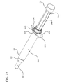
- Figs. 19-24 show an embodiment of syringe assembly having an alternative means for preventing removal of the plunger rod from the barrel after the syringe assembly has been used.
- the assembly includes a barrel 220, a plunger rod 240 and a stopper 260, arranged so that the proximal end of stopper 269 is attached to the distal end of the plunger rod 241.
- the stopper 260 then plunger rod 240 is inserted into the proximal end of the barrel 229.
- a flange 224 is attached at the proximal end 229 of the barrel 220.
- the barrel 220 further includes an attachment hub 252 at the opening in the distal wall 222 of the barrel 220.
- the attachment hub 252 attaches a needle cannula 250 (not shown) to the distal wall 222.
- the assembly may also include a protective cap over the needle cannula (not shown) or a needle retraction system (not shown).
- the barrel can further include a locking rib 223, locking rib or other means for preventing removal of the plunger rod from the barrel, having an interior surface with a smaller diameter than the diameter of the interior surface of the barrel.
- Optional transition diameter regions 225 can also be included to facilitate activation of the means for preventing removal of the plunger rod from the barrel.
- a collar 600 having a distal end 601 and a proximal end 609 is attached to the proximal end 229 of the barrel and includes an annular member 610 having an indentation 611 and a groove 613 defined by the perimeter 227.
- the plunger rod 240 is shown as having a main body 248, a distal end 241 and a proximal end 249.
- the plunger rod 240 further includes a thumb press cap 700 at its proximal end 249 and a stopper-engaging portion 246 at its distal end 241 for attaching the stopper 260 to the plunger rod 240.
- the stopper-engaging portion 246 also includes a plunger recess (not shown) and a retainer 247.
- At least one embodiment of the invention includes a press-fit attachment or other suitable means for retaining the end of the stopper.
- 21-23 includes a distal end 701, proximal end 709 including an end wall 712 and a sidewall 710 between the distal end 701 and the proximal end 709 defining a cavity 713 with the main body 248 of the plunger.
- the side wall 710 further includes a projection 711.
- the stopper 260 shown in Fig. 20 includes a distal end 261 having a peripheral edge 262, a proximal end 269 and a peripheral edge 262 which forms a seal with the interior wall of the barrel 220.
- the peripheral edge 262 of the stopper 260 may have a diameter greater than the diameter of the interior surface of the barrel at the location of the rib 223 and thereby provides a means for separating the stopper from the stopper-engaging portion.
- the stopper 260 can further include a stopper body 264 having a peripheral lip 263 at its proximal end 269 that forms a recess (not shown).
- the peripheral edge 262 of the stopper 260 forms a seal with the interior surface of the barrel 220.
- the retainer 247 of the stopper-engaging portion 246 retains the peripheral lip 263 of the stopper 260 to connect the stopper 260 to the plunger rod 240.
- a gap between the stopper 260 and the distal end of the main body 248 defines a pre-selected axial distance (not shown).
- the distance between the peripheral edge 262 and the end wall 712 of the thumb press cap 700 defines a first length L1 (not shown).
- L1 the distance between the peripheral edge 262 of the stopper 260 and the thumb press cap 700 is reduced to a second length L2 (not shown).
- the user may inject a limited amount of the fluid aspirated or exert a limited force on the plunger rod in the distal direction to flush or expel some of the aspirated fluid, without locking the plunger rod, provided that the syringe assembly is not bottomed.
- a user will typically expel substantially all of the contents of the syringe by bottoming the stopper on the distal wall of the barrel.
- Figs. 23-24 which illustrates the syringe assembly after the reduced length L2 permits the thumb press cap 700 to advance distally into the collar 600 in a nested configuration with the collar.
- the annular member 610 of the collar 600 nests within cavity 713 of the thumb press cap 700.
- the side wall 710 of the thumb press cap 700 nests within the groove 613 of the collar 600.
- the projection 711 and the indentation 611 align to lock the thumb press cap 700 to the collar 600 at the proximal end of the barrel 229.
- stopper and plunger rod can be connected in a fixed relationship such that the distal movement of the stopper and plunger rod permits the thumb press can to advance distally into the collar in a nested configuration with the collar.
- the plunger rod 240 may include a protrusion as described with reference to Figures 1-18 which is permitted to advance distally past the locking rib 223 of the embodiment shown in Fig. 22 to prevent removal of the plunger rod from the barrel.
- the protrusion as described with reference to Figs. 1-18 may be used in conjunction with the thumb press cap 700 and the collar 600 of the embodiments of Figs. 19-24 .
- the protrusion 144, annular extension 400, thumb press 300 having a contoured portion 310 and the thumb press cap 700 and collar 600 can be used alone or in various combinations to prevent removal of the plunger rod or reuse of the syringe assembly.
- Embodiments of the syringe assembly of Figs. 19-24 can also include a visual marker, visual indicator or both, as described with reference to Figs. 14-18 .
- the barrel may include a visual marker that indicates the syringe assembly has been disabled.
- the barrel 220 of one or more embodiments can also include a visual marker aligned with the locking rib 223.
- the syringe assembly can include a visual indicator disposed on the stopper engaging portion 246.
- the syringe barrel may include identifying information on the syringe assembly.
- identifying information can include, but is not limited to one or more of identifying information regarding the contents of the syringe assembly or information regarding the intended recipient.
Landscapes
- Health & Medical Sciences (AREA)
- Vascular Medicine (AREA)
- Engineering & Computer Science (AREA)
- Anesthesiology (AREA)
- Biomedical Technology (AREA)
- Heart & Thoracic Surgery (AREA)
- Hematology (AREA)
- Life Sciences & Earth Sciences (AREA)
- Animal Behavior & Ethology (AREA)
- General Health & Medical Sciences (AREA)
- Public Health (AREA)
- Veterinary Medicine (AREA)
- Infusion, Injection, And Reservoir Apparatuses (AREA)
Applications Claiming Priority (3)
| Application Number | Priority Date | Filing Date | Title |
|---|---|---|---|
| US94339707P | 2007-06-12 | 2007-06-12 | |
| EP08770836.8A EP2167175B1 (de) | 2007-06-12 | 2008-06-12 | Spritze mit deaktivierungsmechanismus |
| PCT/US2008/066705 WO2008154630A2 (en) | 2007-06-12 | 2008-06-12 | Syringe with disabling mechanism |
Related Parent Applications (2)
| Application Number | Title | Priority Date | Filing Date |
|---|---|---|---|
| EP08770836.8A Division-Into EP2167175B1 (de) | 2007-06-12 | 2008-06-12 | Spritze mit deaktivierungsmechanismus |
| EP08770836.8A Division EP2167175B1 (de) | 2007-06-12 | 2008-06-12 | Spritze mit deaktivierungsmechanismus |
Publications (2)
| Publication Number | Publication Date |
|---|---|
| EP2929901A1 true EP2929901A1 (de) | 2015-10-14 |
| EP2929901B1 EP2929901B1 (de) | 2021-03-17 |
Family
ID=39731158
Family Applications (4)
| Application Number | Title | Priority Date | Filing Date |
|---|---|---|---|
| EP08770788.1A Active EP2170441B1 (de) | 2007-06-12 | 2008-06-12 | Spritze mit deaktivierungsmechanismus |
| EP15155440.9A Active EP2929901B1 (de) | 2007-06-12 | 2008-06-12 | Spritze mit deaktivierungsmechanismus |
| EP15155542.2A Active EP2929902B1 (de) | 2007-06-12 | 2008-06-12 | Spritze mit Deaktivierungsmechanismus |
| EP08770836.8A Active EP2167175B1 (de) | 2007-06-12 | 2008-06-12 | Spritze mit deaktivierungsmechanismus |
Family Applications Before (1)
| Application Number | Title | Priority Date | Filing Date |
|---|---|---|---|
| EP08770788.1A Active EP2170441B1 (de) | 2007-06-12 | 2008-06-12 | Spritze mit deaktivierungsmechanismus |
Family Applications After (2)
| Application Number | Title | Priority Date | Filing Date |
|---|---|---|---|
| EP15155542.2A Active EP2929902B1 (de) | 2007-06-12 | 2008-06-12 | Spritze mit Deaktivierungsmechanismus |
| EP08770836.8A Active EP2167175B1 (de) | 2007-06-12 | 2008-06-12 | Spritze mit deaktivierungsmechanismus |
Country Status (14)
| Country | Link |
|---|---|
| US (1) | US7972303B2 (de) |
| EP (4) | EP2170441B1 (de) |
| JP (2) | JP5409615B2 (de) |
| KR (2) | KR101509270B1 (de) |
| CN (2) | CN101808686B (de) |
| AU (2) | AU2008261631B2 (de) |
| BR (2) | BRPI0813908B1 (de) |
| CA (2) | CA2691359C (de) |
| ES (4) | ES2632714T3 (de) |
| MX (2) | MX2009013640A (de) |
| NZ (2) | NZ582278A (de) |
| RU (2) | RU2483760C2 (de) |
| WO (2) | WO2008154630A2 (de) |
| ZA (2) | ZA200909134B (de) |
Families Citing this family (52)
| Publication number | Priority date | Publication date | Assignee | Title |
|---|---|---|---|---|
| US8425549B2 (en) | 2002-07-23 | 2013-04-23 | Reverse Medical Corporation | Systems and methods for removing obstructive matter from body lumens and treating vascular defects |
| US7972302B2 (en) | 2007-06-12 | 2011-07-05 | Becton, Dickinson And Company | Syringe with disabling mechanism |
| JP5409615B2 (ja) | 2007-06-12 | 2014-02-05 | ベクトン・ディキンソン・アンド・カンパニー | 不能化機構付き注射器 |
| US8361018B2 (en) * | 2007-06-12 | 2013-01-29 | Becton, Dickinson And Company | Syringe with disabling mechanism |
| US8088140B2 (en) | 2008-05-19 | 2012-01-03 | Mindframe, Inc. | Blood flow restorative and embolus removal methods |
| US8066757B2 (en) | 2007-10-17 | 2011-11-29 | Mindframe, Inc. | Blood flow restoration and thrombus management methods |
| US11337714B2 (en) | 2007-10-17 | 2022-05-24 | Covidien Lp | Restoring blood flow and clot removal during acute ischemic stroke |
| US9198687B2 (en) | 2007-10-17 | 2015-12-01 | Covidien Lp | Acute stroke revascularization/recanalization systems processes and products thereby |
| US8585713B2 (en) | 2007-10-17 | 2013-11-19 | Covidien Lp | Expandable tip assembly for thrombus management |
| US10123803B2 (en) | 2007-10-17 | 2018-11-13 | Covidien Lp | Methods of managing neurovascular obstructions |
| US9220522B2 (en) | 2007-10-17 | 2015-12-29 | Covidien Lp | Embolus removal systems with baskets |
| US8926680B2 (en) | 2007-11-12 | 2015-01-06 | Covidien Lp | Aneurysm neck bridging processes with revascularization systems methods and products thereby |
| US8062254B2 (en) | 2008-01-08 | 2011-11-22 | MacLean, LLC | Spring driven adjustable oral syringe |
| CN103549986B (zh) | 2008-02-22 | 2015-12-09 | 泰科保健集团有限合伙公司 | 可去除的结合的血栓装置团块 |
| WO2009126935A2 (en) | 2008-04-11 | 2009-10-15 | Mindframe, Inc. | Monorail neuro-microcatheter for delivery of medical devices to treat stroke, processes and products thereby |
| ES2742537T3 (es) | 2008-06-26 | 2020-02-14 | Becton Dickinson Co | Jeringa con prevención de reutilización pasiva que emplea un bloqueo anular de retención |
| AU2009345109B2 (en) | 2009-04-27 | 2013-05-23 | Becton, Dickinson And Company | Passive reuse prevention syringe that uses a tip lock |
| EP2445554B1 (de) | 2009-06-26 | 2016-11-16 | Becton, Dickinson and Company | Spritze mit flanschsicherung für passive wiederverwendungsverhinderung |
| IN2012DN00344A (de) | 2009-07-10 | 2015-05-08 | Becton Dickinson Co | |
| EP3284494A1 (de) | 2009-07-30 | 2018-02-21 | Tandem Diabetes Care, Inc. | Tragbares infusionspumpensystem |
| WO2011036134A2 (en) * | 2009-09-23 | 2011-03-31 | Sanofi-Aventis Deutschland Gmbh | Assembly and indicator for a drug delivery device |
| US20120283662A1 (en) * | 2009-09-30 | 2012-11-08 | Sanofi-Aventis Deutschland Gmbh | Method for Assembling a Drug Delivery Device, Assembly for a Drug Delivery Device and Piston Rod for a Drug Delivery Device |
| MX369242B (es) | 2010-05-20 | 2019-11-01 | Becton Dickinson Co | Dispositivo de administracion de farmacos. |
| US8556855B2 (en) * | 2010-07-22 | 2013-10-15 | Becton, Dickinson And Company | Dual chamber syringe with retractable needle |
| US8556854B2 (en) | 2010-07-22 | 2013-10-15 | Becton, Dickinson And Company | Dual chamber syringe with retractable needle |
| US9550030B2 (en) * | 2010-07-22 | 2017-01-24 | Becton, Dickinson And Company | Dual chamber syringe with retractable needle |
| US8721599B2 (en) * | 2010-07-22 | 2014-05-13 | Becton, Dickinson And Company | Dual chamber passive retraction needle syringe |
| CN102371014A (zh) * | 2010-08-20 | 2012-03-14 | 江苏康宝医疗器械有限公司 | 自毁式一次性注射器 |
| US20120046411A1 (en) | 2010-08-20 | 2012-02-23 | Becton, Dickinson And Company | Recycled Resin Compositions And Disposable Medical Devices Made Therefrom |
| EP2691133B1 (de) * | 2011-03-28 | 2018-01-10 | Becton, Dickinson and Company | Kunststoffverschluss |
| USD667109S1 (en) | 2011-11-04 | 2012-09-11 | Becton, Dickinson And Company | Syringe plunger rod |
| USD667107S1 (en) | 2011-11-04 | 2012-09-11 | Becton, Dickinson And Company | Syringe plunger rod |
| US20130116628A1 (en) | 2011-11-04 | 2013-05-09 | Becton, Dickinson And Company | Recycled Resin Compositions And Disposable Medical Devices Made Therefrom |
| USD673675S1 (en) | 2011-11-04 | 2013-01-01 | Becton, Dickinson And Company | Syringe plunger rod |
| USD673268S1 (en) | 2011-11-04 | 2012-12-25 | Becton, Dickinson And Company | Syringe plunger rod |
| USD667108S1 (en) | 2011-11-04 | 2012-09-11 | Becton, Dickinson And Company | Syringe plunger rod |
| USD713028S1 (en) | 2011-11-04 | 2014-09-09 | Becton, Dickinson And Company | Syringe plunger rod |
| US9180242B2 (en) | 2012-05-17 | 2015-11-10 | Tandem Diabetes Care, Inc. | Methods and devices for multiple fluid transfer |
| HRP20211572T1 (hr) | 2012-06-01 | 2022-02-04 | Novartis Ag | Štrcaljka |
| JOP20200175A1 (ar) | 2012-07-03 | 2017-06-16 | Novartis Ag | حقنة |
| KR101254705B1 (ko) | 2012-10-08 | 2013-04-15 | (주)나비바이오텍 | 동물 난소 기능 불활화를 위한 약물 주입기구 |
| US9173998B2 (en) | 2013-03-14 | 2015-11-03 | Tandem Diabetes Care, Inc. | System and method for detecting occlusions in an infusion pump |
| EP3127570B1 (de) * | 2014-03-31 | 2020-05-06 | Terumo Kabushiki Kaisha | Spritze |
| WO2015187518A1 (en) * | 2014-06-04 | 2015-12-10 | Merck Sharp & Dohme Corp. | Prefilled disposable injection device |
| JP6635698B2 (ja) * | 2015-07-14 | 2020-01-29 | ぺんてる株式会社 | 抵抗構造によりプランジャの可動範囲を制限したアプリケータ |
| WO2018175929A1 (en) * | 2017-03-24 | 2018-09-27 | Carefusion 303, Inc. | Automatic drug compounder with hygroscopic member |
| US11083847B2 (en) | 2018-01-26 | 2021-08-10 | Becton, Dickinson And Company | Flush syringe with flip cap |
| RU2699262C1 (ru) * | 2018-04-24 | 2019-09-04 | Дмитрий Леонидович Король | Одноразовый шприц |
| WO2019222687A1 (en) * | 2018-05-18 | 2019-11-21 | Bard Peripheral Vascular, Inc. | Catheter with flaring tip |
| JP7107499B2 (ja) | 2018-06-21 | 2022-07-27 | 株式会社松風 | 注入器 |
| JP6969021B2 (ja) * | 2018-12-27 | 2021-11-24 | 株式会社ダイセル | 無針注射器 |
| RU206270U1 (ru) * | 2021-03-29 | 2021-09-02 | Федеральное государственное бюджетное образовательное учреждение высшего образования "Курский государственный медицинский университет" Министерства здравоохранения Российской Федерации | Шприц для дозированного введения лекарственных препаратов лабораторным животным |
Citations (9)
| Publication number | Priority date | Publication date | Assignee | Title |
|---|---|---|---|---|
| GB2197792A (en) * | 1986-11-26 | 1988-06-02 | Power Richard Kiteley | Disposable syringes |
| BE1001579A4 (nl) * | 1988-04-08 | 1989-12-05 | Frank Dumon | Injectiespuit voor eenmalig gebruik. |
| WO1990003818A1 (en) * | 1988-10-14 | 1990-04-19 | Agven Medical Corporation | Syringe |
| FR2686517A1 (fr) * | 1992-01-27 | 1993-07-30 | Lardenois Robert | Seringue a usage unique. |
| RU2017505C1 (ru) * | 1991-02-25 | 1994-08-15 | Сергей Иванович Нестеренко | Шприц |
| US5370620A (en) * | 1992-12-28 | 1994-12-06 | Shonfeld; David | Single use hypodermic syringe |
| FR2821562A1 (fr) * | 2001-03-05 | 2002-09-06 | Becton Dickinson France | Dispositif a usage medical, notamment seringue, a securite renforcee |
| WO2003037411A1 (de) * | 2001-10-31 | 2003-05-08 | Destroject Gmbh | Einmalspritze für den medizinischen gebrauch |
| WO2007101090A2 (en) * | 2006-02-24 | 2007-09-07 | Safety Medical International, Inc. | Retractable needle syringe with needle trap |
Family Cites Families (32)
| Publication number | Priority date | Publication date | Assignee | Title |
|---|---|---|---|---|
| US4367738A (en) * | 1981-10-28 | 1983-01-11 | Janssen Pharmaceutica Inc. | Pre-filled syringe for abusable drugs |
| NO157085C (no) * | 1986-01-07 | 1988-01-20 | Chr Sandsdalen | Anordning ved injeksjonssprte for engangsbruk. |
| IN169618B (de) | 1987-06-25 | 1991-11-23 | Agven Medical Corp Ltd | |
| MY104360A (en) * | 1987-12-30 | 1994-03-31 | Verlier Jacques | Non-reusable syringe |
| WO1989006146A1 (en) * | 1987-12-30 | 1989-07-13 | Jacques Verlier | Non-reusable syringe |
| US4932941A (en) * | 1988-03-14 | 1990-06-12 | Min Kyung M | Non-reusable disposable syringe |
| US5085638A (en) | 1988-03-31 | 1992-02-04 | David Farbstein | Single use disposable syringe |
| US4973310A (en) | 1988-12-30 | 1990-11-27 | Becton, Dickinson And Company | Single-use syringe |
| IT1230297B (it) | 1989-07-05 | 1991-10-18 | Carmelo Lo Duca | Siringa utilizzabile una sola volta. |
| US5114405A (en) | 1990-05-21 | 1992-05-19 | Winter Douglas A | Single use tamper resistant syringe |
| US5053010A (en) | 1990-10-03 | 1991-10-01 | Triad Technology | Safety syringe with retractable needle |
| FR2668067B1 (fr) * | 1990-10-23 | 1998-01-16 | Lg Medical Sa | Seringue d'injection d'un produit vers le corps d'un receveur, piston pour seringue et application de cette seringue a l'introduction d'une prothese vasculaire. |
| US5106372A (en) | 1991-05-03 | 1992-04-21 | Sherwood Medical Company | Single use syringe |
| US5269760A (en) | 1991-11-14 | 1993-12-14 | Bina Dale C | Non-reusable hypodermic syringe |
| US5211629A (en) | 1991-12-23 | 1993-05-18 | Pressly William B S | Safety syringe |
| FR2689765B1 (fr) * | 1992-04-10 | 1999-07-09 | Constantin Vounatsos | Seringue uni injection. |
| US6090077A (en) | 1995-05-11 | 2000-07-18 | Shaw; Thomas J. | Syringe plunger assembly and barrel |
| GB2350317B (en) | 1996-07-15 | 2001-01-10 | Star Syringe Ltd | Apparatus for making syringes |
| US5989219A (en) | 1998-01-23 | 1999-11-23 | Becton, Dickinson And Company | Single-use syringe |
| EP1106194A1 (de) | 1999-12-03 | 2001-06-13 | Euro-China Farma, S.L. | Wegwerfbare Einwegspritze |
| US6599269B1 (en) | 1999-12-03 | 2003-07-29 | Becton Dickinson And Company | Single-use syringe |
| US20030032928A1 (en) * | 2000-03-02 | 2003-02-13 | Morihiro Sudo | Prefilled syringe assembly |
| JP2003260136A (ja) * | 2002-03-08 | 2003-09-16 | Top:Kk | 注射器 |
| UA53537C2 (en) * | 2002-07-15 | 2005-01-17 | Amtech Ltd Ukrainian German Jo | Injection syringe |
| BRPI0315217B8 (pt) * | 2002-10-11 | 2021-06-22 | Becton Dickinson Co | "conjunto de seringa de uso único tendo uma blindagem de segurança" |
| AU2003283620A1 (en) | 2002-11-19 | 2004-06-15 | Peter Balfour Dugmore | Hypodermic safety syringe |
| US20040176722A1 (en) * | 2003-03-05 | 2004-09-09 | Capes David Francis | Single-use syringe |
| US20040186437A1 (en) * | 2003-03-20 | 2004-09-23 | Frenette Claude E. | Content-coded medical syringe, syringe set and syringe content identification method |
| US7331934B2 (en) | 2003-07-30 | 2008-02-19 | Becton Dickinson Co | Syringe assembly having disabling mechanism |
| EP1830909B1 (de) * | 2004-12-21 | 2010-07-28 | Becton, Dickinson & Company | Spritzenanordnng mit deaktivierungsmechanismus |
| RU2281786C1 (ru) * | 2005-02-07 | 2006-08-20 | Государственное образовательное учреждение высшего профессионального образования Новгородский государственный университет им. Ярослава Мудрого | Шприц |
| JP5409615B2 (ja) | 2007-06-12 | 2014-02-05 | ベクトン・ディキンソン・アンド・カンパニー | 不能化機構付き注射器 |
-
2008
- 2008-06-12 JP JP2010512339A patent/JP5409615B2/ja active Active
- 2008-06-12 WO PCT/US2008/066705 patent/WO2008154630A2/en active Application Filing
- 2008-06-12 EP EP08770788.1A patent/EP2170441B1/de active Active
- 2008-06-12 ES ES08770836.8T patent/ES2632714T3/es active Active
- 2008-06-12 CA CA2691359A patent/CA2691359C/en active Active
- 2008-06-12 EP EP15155440.9A patent/EP2929901B1/de active Active
- 2008-06-12 AU AU2008261631A patent/AU2008261631B2/en active Active
- 2008-06-12 BR BRPI0813908-3A patent/BRPI0813908B1/pt active IP Right Grant
- 2008-06-12 ES ES08770788.1T patent/ES2637916T3/es active Active
- 2008-06-12 CN CN200880100445XA patent/CN101808686B/zh active Active
- 2008-06-12 NZ NZ582278A patent/NZ582278A/en not_active IP Right Cessation
- 2008-06-12 KR KR1020107000520A patent/KR101509270B1/ko active IP Right Grant
- 2008-06-12 MX MX2009013640A patent/MX2009013640A/es active IP Right Grant
- 2008-06-12 BR BRPI0813909-1A patent/BRPI0813909B1/pt active IP Right Grant
- 2008-06-12 RU RU2010100326/14A patent/RU2483760C2/ru active
- 2008-06-12 MX MX2009013639A patent/MX2009013639A/es active IP Right Grant
- 2008-06-12 CN CN2008801004303A patent/CN101772360B/zh active Active
- 2008-06-12 US US12/137,854 patent/US7972303B2/en active Active
- 2008-06-12 WO PCT/US2008/066655 patent/WO2008154616A1/en active Application Filing
- 2008-06-12 EP EP15155542.2A patent/EP2929902B1/de active Active
- 2008-06-12 EP EP08770836.8A patent/EP2167175B1/de active Active
- 2008-06-12 RU RU2010100350/14A patent/RU2488410C2/ru active
- 2008-06-12 KR KR1020107000523A patent/KR101509271B1/ko active IP Right Grant
- 2008-06-12 ES ES15155542T patent/ES2764097T3/es active Active
- 2008-06-12 CA CA2691356A patent/CA2691356C/en active Active
- 2008-06-12 AU AU2008261699A patent/AU2008261699B2/en active Active
- 2008-06-12 ES ES15155440T patent/ES2865273T3/es active Active
- 2008-06-12 NZ NZ582279A patent/NZ582279A/xx not_active IP Right Cessation
- 2008-06-12 JP JP2010512349A patent/JP5393660B2/ja active Active
-
2009
- 2009-12-21 ZA ZA200909134A patent/ZA200909134B/xx unknown
- 2009-12-21 ZA ZA2009/09133A patent/ZA200909133B/en unknown
Patent Citations (9)
| Publication number | Priority date | Publication date | Assignee | Title |
|---|---|---|---|---|
| GB2197792A (en) * | 1986-11-26 | 1988-06-02 | Power Richard Kiteley | Disposable syringes |
| BE1001579A4 (nl) * | 1988-04-08 | 1989-12-05 | Frank Dumon | Injectiespuit voor eenmalig gebruik. |
| WO1990003818A1 (en) * | 1988-10-14 | 1990-04-19 | Agven Medical Corporation | Syringe |
| RU2017505C1 (ru) * | 1991-02-25 | 1994-08-15 | Сергей Иванович Нестеренко | Шприц |
| FR2686517A1 (fr) * | 1992-01-27 | 1993-07-30 | Lardenois Robert | Seringue a usage unique. |
| US5370620A (en) * | 1992-12-28 | 1994-12-06 | Shonfeld; David | Single use hypodermic syringe |
| FR2821562A1 (fr) * | 2001-03-05 | 2002-09-06 | Becton Dickinson France | Dispositif a usage medical, notamment seringue, a securite renforcee |
| WO2003037411A1 (de) * | 2001-10-31 | 2003-05-08 | Destroject Gmbh | Einmalspritze für den medizinischen gebrauch |
| WO2007101090A2 (en) * | 2006-02-24 | 2007-09-07 | Safety Medical International, Inc. | Retractable needle syringe with needle trap |
Also Published As
Similar Documents
| Publication | Publication Date | Title |
|---|---|---|
| EP2929901B1 (de) | Spritze mit deaktivierungsmechanismus | |
| US7972302B2 (en) | Syringe with disabling mechanism | |
| EP2808048A1 (de) | Einwegspritze |
Legal Events
| Date | Code | Title | Description |
|---|---|---|---|
| PUAI | Public reference made under article 153(3) epc to a published international application that has entered the european phase |
Free format text: ORIGINAL CODE: 0009012 |
|
| AC | Divisional application: reference to earlier application |
Ref document number: 2167175 Country of ref document: EP Kind code of ref document: P |
|
| AK | Designated contracting states |
Kind code of ref document: A1 Designated state(s): AT BE BG CH CY CZ DE DK EE ES FI FR GB GR HR HU IE IS IT LI LT LU LV MC MT NL NO PL PT RO SE SI SK TR |
|
| 17P | Request for examination filed |
Effective date: 20160408 |
|
| RBV | Designated contracting states (corrected) |
Designated state(s): AT BE BG CH CY CZ DE DK EE ES FI FR GB GR HR HU IE IS IT LI LT LU LV MC MT NL NO PL PT RO SE SI SK TR |
|
| RAP1 | Party data changed (applicant data changed or rights of an application transferred) |
Owner name: BECTON, DICKINSON AND COMPANY |
|
| STAA | Information on the status of an ep patent application or granted ep patent |
Free format text: STATUS: EXAMINATION IS IN PROGRESS |
|
| 17Q | First examination report despatched |
Effective date: 20180115 |
|
| GRAP | Despatch of communication of intention to grant a patent |
Free format text: ORIGINAL CODE: EPIDOSNIGR1 |
|
| STAA | Information on the status of an ep patent application or granted ep patent |
Free format text: STATUS: GRANT OF PATENT IS INTENDED |
|
| INTG | Intention to grant announced |
Effective date: 20201013 |
|
| GRAS | Grant fee paid |
Free format text: ORIGINAL CODE: EPIDOSNIGR3 |
|
| GRAA | (expected) grant |
Free format text: ORIGINAL CODE: 0009210 |
|
| STAA | Information on the status of an ep patent application or granted ep patent |
Free format text: STATUS: THE PATENT HAS BEEN GRANTED |
|
| AC | Divisional application: reference to earlier application |
Ref document number: 2167175 Country of ref document: EP Kind code of ref document: P |
|
| AK | Designated contracting states |
Kind code of ref document: B1 Designated state(s): AT BE BG CH CY CZ DE DK EE ES FI FR GB GR HR HU IE IS IT LI LT LU LV MC MT NL NO PL PT RO SE SI SK TR |
|
| REG | Reference to a national code |
Ref country code: GB Ref legal event code: FG4D |
|
| REG | Reference to a national code |
Ref country code: CH Ref legal event code: EP |
|
| REG | Reference to a national code |
Ref country code: IE Ref legal event code: FG4D |
|
| REG | Reference to a national code |
Ref country code: AT Ref legal event code: REF Ref document number: 1371659 Country of ref document: AT Kind code of ref document: T Effective date: 20210415 Ref country code: DE Ref legal event code: R096 Ref document number: 602008063790 Country of ref document: DE |
|
| REG | Reference to a national code |
Ref country code: LT Ref legal event code: MG9D |
|
| PG25 | Lapsed in a contracting state [announced via postgrant information from national office to epo] |
Ref country code: FI Free format text: LAPSE BECAUSE OF FAILURE TO SUBMIT A TRANSLATION OF THE DESCRIPTION OR TO PAY THE FEE WITHIN THE PRESCRIBED TIME-LIMIT Effective date: 20210317 Ref country code: HR Free format text: LAPSE BECAUSE OF FAILURE TO SUBMIT A TRANSLATION OF THE DESCRIPTION OR TO PAY THE FEE WITHIN THE PRESCRIBED TIME-LIMIT Effective date: 20210317 Ref country code: GR Free format text: LAPSE BECAUSE OF FAILURE TO SUBMIT A TRANSLATION OF THE DESCRIPTION OR TO PAY THE FEE WITHIN THE PRESCRIBED TIME-LIMIT Effective date: 20210618 Ref country code: BG Free format text: LAPSE BECAUSE OF FAILURE TO SUBMIT A TRANSLATION OF THE DESCRIPTION OR TO PAY THE FEE WITHIN THE PRESCRIBED TIME-LIMIT Effective date: 20210617 Ref country code: NO Free format text: LAPSE BECAUSE OF FAILURE TO SUBMIT A TRANSLATION OF THE DESCRIPTION OR TO PAY THE FEE WITHIN THE PRESCRIBED TIME-LIMIT Effective date: 20210617 |
|
| REG | Reference to a national code |
Ref country code: AT Ref legal event code: MK05 Ref document number: 1371659 Country of ref document: AT Kind code of ref document: T Effective date: 20210317 |
|
| REG | Reference to a national code |
Ref country code: NL Ref legal event code: MP Effective date: 20210317 |
|
| PG25 | Lapsed in a contracting state [announced via postgrant information from national office to epo] |
Ref country code: SE Free format text: LAPSE BECAUSE OF FAILURE TO SUBMIT A TRANSLATION OF THE DESCRIPTION OR TO PAY THE FEE WITHIN THE PRESCRIBED TIME-LIMIT Effective date: 20210317 Ref country code: LV Free format text: LAPSE BECAUSE OF FAILURE TO SUBMIT A TRANSLATION OF THE DESCRIPTION OR TO PAY THE FEE WITHIN THE PRESCRIBED TIME-LIMIT Effective date: 20210317 |
|
| PG25 | Lapsed in a contracting state [announced via postgrant information from national office to epo] |
Ref country code: NL Free format text: LAPSE BECAUSE OF FAILURE TO SUBMIT A TRANSLATION OF THE DESCRIPTION OR TO PAY THE FEE WITHIN THE PRESCRIBED TIME-LIMIT Effective date: 20210317 |
|
| REG | Reference to a national code |
Ref country code: ES Ref legal event code: FG2A Ref document number: 2865273 Country of ref document: ES Kind code of ref document: T3 Effective date: 20211015 |
|
| PG25 | Lapsed in a contracting state [announced via postgrant information from national office to epo] |
Ref country code: EE Free format text: LAPSE BECAUSE OF FAILURE TO SUBMIT A TRANSLATION OF THE DESCRIPTION OR TO PAY THE FEE WITHIN THE PRESCRIBED TIME-LIMIT Effective date: 20210317 Ref country code: CZ Free format text: LAPSE BECAUSE OF FAILURE TO SUBMIT A TRANSLATION OF THE DESCRIPTION OR TO PAY THE FEE WITHIN THE PRESCRIBED TIME-LIMIT Effective date: 20210317 Ref country code: LT Free format text: LAPSE BECAUSE OF FAILURE TO SUBMIT A TRANSLATION OF THE DESCRIPTION OR TO PAY THE FEE WITHIN THE PRESCRIBED TIME-LIMIT Effective date: 20210317 Ref country code: AT Free format text: LAPSE BECAUSE OF FAILURE TO SUBMIT A TRANSLATION OF THE DESCRIPTION OR TO PAY THE FEE WITHIN THE PRESCRIBED TIME-LIMIT Effective date: 20210317 |
|
| PG25 | Lapsed in a contracting state [announced via postgrant information from national office to epo] |
Ref country code: IS Free format text: LAPSE BECAUSE OF FAILURE TO SUBMIT A TRANSLATION OF THE DESCRIPTION OR TO PAY THE FEE WITHIN THE PRESCRIBED TIME-LIMIT Effective date: 20210717 Ref country code: PT Free format text: LAPSE BECAUSE OF FAILURE TO SUBMIT A TRANSLATION OF THE DESCRIPTION OR TO PAY THE FEE WITHIN THE PRESCRIBED TIME-LIMIT Effective date: 20210719 Ref country code: PL Free format text: LAPSE BECAUSE OF FAILURE TO SUBMIT A TRANSLATION OF THE DESCRIPTION OR TO PAY THE FEE WITHIN THE PRESCRIBED TIME-LIMIT Effective date: 20210317 Ref country code: SK Free format text: LAPSE BECAUSE OF FAILURE TO SUBMIT A TRANSLATION OF THE DESCRIPTION OR TO PAY THE FEE WITHIN THE PRESCRIBED TIME-LIMIT Effective date: 20210317 Ref country code: RO Free format text: LAPSE BECAUSE OF FAILURE TO SUBMIT A TRANSLATION OF THE DESCRIPTION OR TO PAY THE FEE WITHIN THE PRESCRIBED TIME-LIMIT Effective date: 20210317 |
|
| REG | Reference to a national code |
Ref country code: DE Ref legal event code: R097 Ref document number: 602008063790 Country of ref document: DE |
|
| PLBE | No opposition filed within time limit |
Free format text: ORIGINAL CODE: 0009261 |
|
| STAA | Information on the status of an ep patent application or granted ep patent |
Free format text: STATUS: NO OPPOSITION FILED WITHIN TIME LIMIT |
|
| PG25 | Lapsed in a contracting state [announced via postgrant information from national office to epo] |
Ref country code: DK Free format text: LAPSE BECAUSE OF FAILURE TO SUBMIT A TRANSLATION OF THE DESCRIPTION OR TO PAY THE FEE WITHIN THE PRESCRIBED TIME-LIMIT Effective date: 20210317 Ref country code: MC Free format text: LAPSE BECAUSE OF FAILURE TO SUBMIT A TRANSLATION OF THE DESCRIPTION OR TO PAY THE FEE WITHIN THE PRESCRIBED TIME-LIMIT Effective date: 20210317 |
|
| REG | Reference to a national code |
Ref country code: CH Ref legal event code: PL |
|
| 26N | No opposition filed |
Effective date: 20211220 |
|
| PG25 | Lapsed in a contracting state [announced via postgrant information from national office to epo] |
Ref country code: SI Free format text: LAPSE BECAUSE OF FAILURE TO SUBMIT A TRANSLATION OF THE DESCRIPTION OR TO PAY THE FEE WITHIN THE PRESCRIBED TIME-LIMIT Effective date: 20210317 |
|
| REG | Reference to a national code |
Ref country code: BE Ref legal event code: MM Effective date: 20210630 |
|
| PG25 | Lapsed in a contracting state [announced via postgrant information from national office to epo] |
Ref country code: LU Free format text: LAPSE BECAUSE OF NON-PAYMENT OF DUE FEES Effective date: 20210612 |
|
| PG25 | Lapsed in a contracting state [announced via postgrant information from national office to epo] |
Ref country code: LI Free format text: LAPSE BECAUSE OF NON-PAYMENT OF DUE FEES Effective date: 20210630 Ref country code: CH Free format text: LAPSE BECAUSE OF NON-PAYMENT OF DUE FEES Effective date: 20210630 |
|
| PG25 | Lapsed in a contracting state [announced via postgrant information from national office to epo] |
Ref country code: IS Free format text: LAPSE BECAUSE OF FAILURE TO SUBMIT A TRANSLATION OF THE DESCRIPTION OR TO PAY THE FEE WITHIN THE PRESCRIBED TIME-LIMIT Effective date: 20210717 |
|
| PG25 | Lapsed in a contracting state [announced via postgrant information from national office to epo] |
Ref country code: BE Free format text: LAPSE BECAUSE OF NON-PAYMENT OF DUE FEES Effective date: 20210630 |
|
| PG25 | Lapsed in a contracting state [announced via postgrant information from national office to epo] |
Ref country code: HU Free format text: LAPSE BECAUSE OF FAILURE TO SUBMIT A TRANSLATION OF THE DESCRIPTION OR TO PAY THE FEE WITHIN THE PRESCRIBED TIME-LIMIT; INVALID AB INITIO Effective date: 20080612 Ref country code: CY Free format text: LAPSE BECAUSE OF FAILURE TO SUBMIT A TRANSLATION OF THE DESCRIPTION OR TO PAY THE FEE WITHIN THE PRESCRIBED TIME-LIMIT Effective date: 20210317 |
|
| PGFP | Annual fee paid to national office [announced via postgrant information from national office to epo] |
Ref country code: ES Payment date: 20230703 Year of fee payment: 16 |
|
| PG25 | Lapsed in a contracting state [announced via postgrant information from national office to epo] |
Ref country code: TR Free format text: LAPSE BECAUSE OF FAILURE TO SUBMIT A TRANSLATION OF THE DESCRIPTION OR TO PAY THE FEE WITHIN THE PRESCRIBED TIME-LIMIT Effective date: 20210317 |
|
| PGFP | Annual fee paid to national office [announced via postgrant information from national office to epo] |
Ref country code: IE Payment date: 20240523 Year of fee payment: 17 |
|
| PGFP | Annual fee paid to national office [announced via postgrant information from national office to epo] |
Ref country code: GB Payment date: 20240521 Year of fee payment: 17 |
|
| PGFP | Annual fee paid to national office [announced via postgrant information from national office to epo] |
Ref country code: DE Payment date: 20240521 Year of fee payment: 17 |
|
| PGFP | Annual fee paid to national office [announced via postgrant information from national office to epo] |
Ref country code: IT Payment date: 20240522 Year of fee payment: 17 Ref country code: FR Payment date: 20240522 Year of fee payment: 17 |