EP2928811B1 - Dispositif permettant de vider des récipients - Google Patents
Dispositif permettant de vider des récipients Download PDFInfo
- Publication number
- EP2928811B1 EP2928811B1 EP13814463.9A EP13814463A EP2928811B1 EP 2928811 B1 EP2928811 B1 EP 2928811B1 EP 13814463 A EP13814463 A EP 13814463A EP 2928811 B1 EP2928811 B1 EP 2928811B1
- Authority
- EP
- European Patent Office
- Prior art keywords
- container
- removal
- closure
- holding
- flow connection
- Prior art date
- Legal status (The legal status is an assumption and is not a legal conclusion. Google has not performed a legal analysis and makes no representation as to the accuracy of the status listed.)
- Not-in-force
Links
- 239000007788 liquid Substances 0.000 claims description 35
- 238000005520 cutting process Methods 0.000 description 15
- 239000004033 plastic Substances 0.000 description 8
- 239000000463 material Substances 0.000 description 5
- 230000002093 peripheral effect Effects 0.000 description 5
- 238000004140 cleaning Methods 0.000 description 3
- 238000004891 communication Methods 0.000 description 3
- 229930040373 Paraformaldehyde Natural products 0.000 description 2
- 239000004743 Polypropylene Substances 0.000 description 2
- 238000013461 design Methods 0.000 description 2
- 239000012530 fluid Substances 0.000 description 2
- 238000003780 insertion Methods 0.000 description 2
- 230000037431 insertion Effects 0.000 description 2
- 238000000034 method Methods 0.000 description 2
- -1 polyoxymethylene Polymers 0.000 description 2
- 229920006324 polyoxymethylene Polymers 0.000 description 2
- 239000000565 sealant Substances 0.000 description 2
- 239000000725 suspension Substances 0.000 description 2
- 206010053648 Vascular occlusion Diseases 0.000 description 1
- 230000015572 biosynthetic process Effects 0.000 description 1
- 239000000969 carrier Substances 0.000 description 1
- 230000001419 dependent effect Effects 0.000 description 1
- 238000011161 development Methods 0.000 description 1
- 230000018109 developmental process Effects 0.000 description 1
- 238000000605 extraction Methods 0.000 description 1
- 238000004519 manufacturing process Methods 0.000 description 1
- 229920001155 polypropylene Polymers 0.000 description 1
- 238000007789 sealing Methods 0.000 description 1
- 239000000126 substance Substances 0.000 description 1
Images

Classifications
-
- B—PERFORMING OPERATIONS; TRANSPORTING
- B67—OPENING, CLOSING OR CLEANING BOTTLES, JARS OR SIMILAR CONTAINERS; LIQUID HANDLING
- B67D—DISPENSING, DELIVERING OR TRANSFERRING LIQUIDS, NOT OTHERWISE PROVIDED FOR
- B67D1/00—Apparatus or devices for dispensing beverages on draught
-
- B—PERFORMING OPERATIONS; TRANSPORTING
- B67—OPENING, CLOSING OR CLEANING BOTTLES, JARS OR SIMILAR CONTAINERS; LIQUID HANDLING
- B67D—DISPENSING, DELIVERING OR TRANSFERRING LIQUIDS, NOT OTHERWISE PROVIDED FOR
- B67D1/00—Apparatus or devices for dispensing beverages on draught
- B67D1/0001—Apparatus or devices for dispensing beverages on draught by squeezing collapsible or flexible storage containers
-
- B—PERFORMING OPERATIONS; TRANSPORTING
- B67—OPENING, CLOSING OR CLEANING BOTTLES, JARS OR SIMILAR CONTAINERS; LIQUID HANDLING
- B67D—DISPENSING, DELIVERING OR TRANSFERRING LIQUIDS, NOT OTHERWISE PROVIDED FOR
- B67D1/00—Apparatus or devices for dispensing beverages on draught
- B67D1/08—Details
- B67D1/0829—Keg connection means
Definitions
- the present invention relates to a device for emptying containers.
- Such devices are known from the prior art, for example as dispensing equipment.
- the pamphlets show GB 2 436 828 and WO 03/097519 such devices.
- devices are known, for example, in which the emptying of the containers takes place in such a way that gas is fed into the container and the liquid is thus forced out of the container by the resulting overpressure.
- devices have become known in recent times, in which the emptying of the container takes place in that this container is compressed and so the liquid located inside is pushed out of the container.
- the present invention is therefore based on the object to make cleaning operations for such facilities easier and possibly completely waive this.
- a device for removing fluids from deformable containers has a first holding device for holding a first region of a container and a second holding device for holding a second region of the container, this second region being spaced from the first region. Furthermore, the device has a removal device in order to remove liquid from the container, and a drive device which moves the second holding device with respect to the first holding device in a predetermined direction of movement.
- the removal device is removably arranged on the device and at least one element of the removal device is designed as a disposable element.
- the deformable container is a plastic container, in particular made of PET.
- the container is made of another deformable material.
- the removal device is at least partially disposable or not, as usual in the art, remains on the device. In this way, a complex cleaning process for this removal device can be saved.
- the removal device has a flexible hose element.
- the removal device is rigidly designed as a tube and often also firmly integrated into the device.
- this hose element is a disposable hose element.
- the removal device has a flow connection body, which protrudes at least in sections into the container for removing the liquid. It is possible that about a tubular body, which is part of the flow connection body, which protrudes into this during the removal of the liquid or at least projects into the interior of the container.
- the hose connection adjoins this flow connection body at least indirectly and preferably directly. It is possible that the hose member is attached to the flow connection body, but it would also be possible that the hose member is bolted to the flow connection body.
- the flow connection body is designed as a piercing device or has such a piercing device, which pierces a closure or at least one wall of the container for establishing the flow connection with the interior of the container.
- the plastic lid of the container or the closure is pierced and the medium is tapped by means of a plastic line and in particular a disposable plastic line.
- this puncture needle is advantageously designed such that a round circular portion of the lid is not completely demolished due to this formation and thus does not fall into the liquid.
- the disposable line and the piercing means or the piercing needle are disposed of.
- the puncture device consists of a plastic material, since this allows a cost-effective production and easy disposal after use.
- the plastic material of the puncture device preferably has in particular a greater strength than the material of the closure.
- the device has a carrier on which at least one holding device is detachably arranged.
- Carriers are advantageously provided, on which the two holding devices are detachably arranged, so that the device can be adapted to different containers.
- the closure in a further advantageous embodiment, it would also be possible for the closure to have a tubular body, for example in the manner of a cannula, which facilitates the complete emptying of the container during "mechanical emptying", i. when deforming the container allows.
- This tubular body can still push down the bottom of the container at a complete emptying, to empty the remaining liquid.
- the puncture means and the closure are disposed of.
- the container is preferably open here.
- the present invention is further directed to a dispensing assembly for dispensing liquids from containers, and in particular deformable containers, having a liquid dispensing device which in turn comprises a first holding means for holding a first portion of the container and a second holding means for holding a second portion of the container, wherein the second region is spaced from the first region. Furthermore, the removal arrangement on a removal device to remove the container liquid.
- the container here has a closure, which is followed by a tubular body for removing the liquid inside the container.
- This tubular body may be, for example, a hose that extends to a bottom of the container. However, it may also be a fixed tube, wherein preferably in this embodiment, the container is not compressed or deformed during the removal process. It is advantageous - in particular on the closure - provided a sealing element which closes this extending inside the container tubular body.
- this tubular body acts as a riser for the liquid, especially when it is removed or if due to a supplied pressure, the liquid is forced out of the container.
- the medium is emptied here by means of a tube or a long cannula, which preferably extends almost to the container bottom, in which case, in particular, an additional gas supply can take place.
- the supply of gas increases the pressure in the container and the medium is emptied through said cannula.
- the piercing is carried out as in the manner described above using a piercing body. In contrast to the embodiment described above, therefore, there is a further flow connection between the Interior of the container and its outer space, in particular in the form of the gas connection.
- the removal device is removably disposed on the device and at least one element of the removal device is formed as a disposable element. Therefore, it is also proposed in this embodiment that the removal device comprises disposable components. Therefore, also here preferably after each change of the container, the hose and preferably also the piercing needle or the piercing means are changed.
- the removal device has a flow connection body, which is at least partially insertable into the tubular body.
- a piercing means is provided, which, however, adapted in terms of its cross-section to the tubular body so that it can also be introduced into this tubular body in the interior of the container.
- the closure of the container has a valve device.
- this valve device is opened by a movement of the removal device and in particular an insertion or insertion of the removal device or the flow connection body. This will be described in more detail below with reference to the figures.
- the container is closed by the valve with an inserted seal and is preferably already filled via this valve.
- the valve automatically pulled up with and thus closed.
- the valve In an emptying operation, the valve is pushed by a removal device or a stamp to which the disposable line is connected, down and the container can be emptied.
- the removal device is also designed as a disposable element and can be disposed of after complete emptying of the container.
- the valve is closed again before the container is completely emptied.
- the container closure it would also be possible for the container closure to have two closure elements arranged one above the other in the piercing direction. It is possible that the two closure elements each have openings which are offset in this way in the longitudinal direction of the container to each other.
- the valve is formed in the container closure as a check valve, which preferably closes automatically when no removal device is used.
- the closure has at least one element which is movable relative to another element of the closure and in particular is also movable in a longitudinal direction of the container or a piercing direction of the puncturing element.
- the closure also has a suspension element, which urges the valve in a closed or an open position, but preferably in the closed position. It may be a suspension device, which consists of a plastic. In a further advantageous embodiment, the closure has a pierceable and in particular a film-like element.
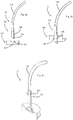
- Fig. 1 shows a schematic representation of a device according to the invention for removing liquid from a container 10 in a schematic representation.
- the device has here a first holding device 2, which serves to hold a first portion 10a of the container.
- This first area of the container 10a is a floor area.
- a second holding device 4 which receives a second region of the container, in particular a mouth region of the container, which also contains the mouth, through which the liquid can be removed from the container. Furthermore, the device has a drive device (not shown in detail), which moves the first holding device relative to the second holding device in the longitudinal direction L of the container.
- the reference numeral 12 indicates the removal device, can be removed by means of the liquid from the container.
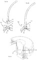
- FIGS. 2a-2c show a first embodiment of a removal device 12 according to the invention.
- This removal device 12 in this case has a flow connection body 122, which establishes a flow connection between a hose 124 and the interior of the container.
- the removal device is made of a plastic, which has a greater strength than the closure material.
- the removal device is made of POM (polyoxymethylene), which has a greater strength than an exemplary closure of PP (polypropylene).
- this flow connection body 122 has a cutting element 126, which is tubular and has an oblique cutting edge 125.
- This cutting edge 125 serves to pierce a seal closure 106, which is arranged on a recess 108 of a container closure 100.
- this recess 108 is such designed to receive the flow connection body 122 and the cutting element 126 accurately.
- FIG. 11 shows a situation where the flow communication body 122 has been inserted into the closure 100.
- the cutting edge 125 has pierced the seal 106.
- the seal 106 is not completely separated by the oblique design of the cutting edge 125, but remains in a region on the closure hang so that it does not fall into the liquid.
- Fig. 2c shows a further illustration of the removal device 12.
- a disc-shaped cover member 132 is shown, which also applies when inserting the flow connection body 12 to the closure.
- This lid member 132 also acts as a stop to which the container 10 is brought and on which it rests during removal of the liquid from the container.
- the reference numeral 128 denotes a connection means with which the hose member 124 is arranged on the flow connection body 122.
- the cover element 132 can in turn be supported relative to the second holding device 4 (not shown).
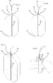
- FIGS. 3a-3e show a further embodiment of the device according to the invention, but here also the container 10 with the first region 10a and the second region 10b is shown.
- the closure 100 has a tubular body 102 which extends into the interior of the container 10.
- Fig. 3b which shows an inserted state of the flow connection body that the piercing means or the cutting element 126 is also introduced into this tubular body 102.
- This tubular body 102 serves to be able to dissipate the liquid as much as possible when the container is squeezed out.
- Fig. 3c shows a perspective view of the in the Fig. 3a and 3d shown device. It can be seen that the closure 100 is screwed onto the mouth of the container here.
- the container 10 also has an external thread 10c onto which the closure, in particular with a circumferential wall 42, is screwed.
- the reference numeral 44 denotes a contact surface to which the cutting element 126, which has the cutting edge 125, applies.
- the reference numeral 48 denotes a recess, by means of which a circumferential pressure can be exerted radially inwardly on the cutting element 126. This shape of the recess can also be used to increase the flow cross-section between the closure 100 and the cutting element 126 during the extraction process.
- Fig. 3e shows a further illustration of a container according to the invention with inserted flow connection body 122 or inserted cutting element 126. It can also be seen here that the cutting element 126 is inserted into the tubular body 102.
- FIGS. 4a-4d show a further embodiment of the present invention.
- the container 10 is squeezed or compressed to empty its contents.
- a gas to additionally be introduced in order to discharge the liquid to be extracted via the tubular body 102, which here functions as a riser.
- a further flow connection between the container 10 and its surroundings could be produced, for example, by introducing a second line into the container, via which the container then a gaseous medium is supplied.
- tubular body 102 is made flexible, but it would also be possible that this is rigid and extends into a lower portion of the container. In this case, it would also be possible for the bottom 10a to be designed in a different way than here in order to ensure that as far as possible all liquid can be detected by the tubular body 102.
- the design of the closure is again similar to that in the FIGS. 3a-3e shown embodiment. Again, the puncture is introduced into a tubular body 102.
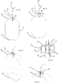
- FIGS. 5a, 5b show a further embodiment of the device according to the invention.
- inserting the flow connection body 12 opens a valve, indicated generally at 70, disposed in the closure 100.
- a flow connection is made to the interior of the container.
- This valve 70 in this case has a valve body 74 which is movable in the longitudinal direction L.
- a valve body 74 which is movable in the longitudinal direction L.
- the valve connecting channels 76 which may extend, for example, in the radial direction, by a peripheral wall 84 which completely surrounds the valve body here in the circumferential direction, circumferentially covered.
- these flow connections 76 are released.
- the reference numeral 82 denotes latching means in which circumferential projections 123 arranged on a flow connection body 122 can be engaged, as in FIG Fig. 5b shown. In this way, upon withdrawal of the flow connection body, the valve 70 can be closed again, or the valve body 74 can be moved upwards.
- Reference numeral 78 denotes a sealant disposed on the valve body 74, which may be an O-ring. In a closed state of the valve 70, this sealant 78 abuts against the peripheral wall 84, thus preventing leakage of liquid between the valve body 74 and the peripheral wall 84.
- Fig. 6 shows a perspective view of the closure with the valve in an open state. Again, it can be seen that the flow connections 76 are released and in this way liquid can be withdrawn through these flow connections upwards.
- a circumferential recess 77 can be seen, which adjoins these flow connections. By this circumferential recess can be increased in an opened state of the valve 70, the flow cross-section for the liquid to be removed.
- the latching means 82 can be seen, which fixes the valve body 74 to the flow connection body 122 in a closed state.
Landscapes
- Containers And Packaging Bodies Having A Special Means To Remove Contents (AREA)
- Apparatus Associated With Microorganisms And Enzymes (AREA)
- Devices For Dispensing Beverages (AREA)
Claims (9)
- Dispositif (1) pour le prélèvement de liquides de récipients (10) déformables, avec un premier dispositif de maintien (2) pour le maintien d'une première région (10a) d'un récipient (10) avec un deuxième dispositif de maintien (4) pour le maintien d'une deuxième région (10b) du récipient, dans lequel cette deuxième région (10b) est espacée de la première région (10a), avec un dispositif de prélèvement (12) pour prélever du liquide du récipient et avec un dispositif d'entraînement (8) qui déplace le deuxième dispositif de maintien (4) par rapport au premier dispositif de maintien (2) dans une direction de déplacement (L) prédéfinie,
caractérisé en ce que
le dispositif de prélèvement (12) est disposé de manière amovible sur le dispositif (1) et au moins un élément du dispositif de prélèvement (12) est formé comme un élément à usage unique, dans lequel le dispositif de prélèvement (12) possède un corps de liaison d'écoulement (122) qui s'étend au moins partiellement dans le récipient (10) pour le prélèvement du liquide. - Dispositif (1) selon la revendication 1,
caractérisé en ce que
pendant le prélèvement du liquide du récipient (10) seulement une liaison d'écoulement est présente entre l'intérieur du récipient (10) et un espace extérieur du récipient. - Dispositif (1) selon au moins l'une des revendications précédentes,
caractérisé en ce que
le dispositif de prélèvement (12) possède un élément en forme de tube (124) flexible. - Dispositif (1) selon au moins l'une des revendications précédentes,
caractérisé en ce que
l'élément en forme de tube (124) flexible est attaché au corps de liaison d'écoulement (122). - Dispositif (1) selon la revendication 4,
caractérisé en ce que
le corps de liaison d'écoulement (122) est formé comme un dispositif de perforation qui perce une fermeture (100) ou au moins une paroi du récipient (10) pour créer la liaison d'écoulement avec l'intérieur du récipient (10). - Ensemble pour le prélèvement pour le prélèvement de liquides de récipients (10) avec un dispositif (1) pour le prélèvement selon la revendication 1, qui possède un premier dispositif de maintien (2) pour le maintien d'une première région (10a) d'un récipient (10) et un deuxième dispositif de maintien (4) pour le maintien d'une deuxième région (10b) du récipient, dans lequel cette deuxième région (10b) est espacée de la première région (10a) ainsi qu'avec un dispositif de prélèvement (12) pour prélever du liquide du récipient
caractérisé en ce que
le récipient possède une fermeture (100) à laquelle à l'intérieur du récipient un corps tubulaire (102) pour le prélèvement de liquide s'attache. - Ensemble pour le prélèvement selon la revendication 6,
caractérisé en ce que
le dispositif de prélèvement (12) est disposé de manière amovible sur le dispositif (1) et au moins un élément du dispositif de prélèvement (12) est formé comme un élément à usage unique. - Ensemble pour le prélèvement selon la revendication 6,
caractérisé en ce que
le dispositif de prélèvement (12) possède un corps de liaison d'écoulement (122) qui peut être inséré dans le corps tubulaire (102). - Ensemble pour le prélèvement selon la revendication 6,
caractérisé en ce que
la fermeture (100) du récipient (10) possède un dispositif de soupape (70).
Applications Claiming Priority (2)
| Application Number | Priority Date | Filing Date | Title |
|---|---|---|---|
| DE102012111850.7A DE102012111850A1 (de) | 2012-12-05 | 2012-12-05 | Vorrichtung zum Entleeren von Behältnissen |
| PCT/EP2013/075650 WO2014086920A1 (fr) | 2012-12-05 | 2013-12-05 | Dispositif permettant de vider des récipients |
Publications (2)
| Publication Number | Publication Date |
|---|---|
| EP2928811A1 EP2928811A1 (fr) | 2015-10-14 |
| EP2928811B1 true EP2928811B1 (fr) | 2018-10-24 |
Family
ID=49885203
Family Applications (1)
| Application Number | Title | Priority Date | Filing Date |
|---|---|---|---|
| EP13814463.9A Not-in-force EP2928811B1 (fr) | 2012-12-05 | 2013-12-05 | Dispositif permettant de vider des récipients |
Country Status (7)
| Country | Link |
|---|---|
| US (1) | US9546084B2 (fr) |
| EP (1) | EP2928811B1 (fr) |
| CN (1) | CN103998369B (fr) |
| BR (1) | BR112015012952A2 (fr) |
| DE (1) | DE102012111850A1 (fr) |
| RU (1) | RU2652950C2 (fr) |
| WO (1) | WO2014086920A1 (fr) |
Families Citing this family (6)
| Publication number | Priority date | Publication date | Assignee | Title |
|---|---|---|---|---|
| DE102013110121A1 (de) * | 2013-09-13 | 2015-03-19 | Krones Ag | Einwegentleerungssystem für Behältnisse |
| DE102014113915A1 (de) * | 2014-09-25 | 2016-03-31 | Krones Aktiengesellschaft | Komprimierbares Kunststoffbehältnis mit Bodentasse |
| DE102014115891A1 (de) * | 2014-10-31 | 2016-05-04 | Krones Aktiengesellschaft | Verschluss, insbesondere Kunststoffverschluss für ein Behältnis |
| DE102015008314A1 (de) * | 2015-06-30 | 2017-01-05 | Krones Ag | Behandlungsmaschine zum Behandlen von Behältnissen und/oder Lebensmitteln mit Zuführung eines Arbeitsmediums |
| AU2018231368B2 (en) * | 2017-03-10 | 2023-10-26 | Carlsberg Breweries A/S | A beverage dispensing system, a beverage dispensing assembly, a method of operating a beverage dispensing system and a pressure housing |
| CN108313965A (zh) * | 2018-02-28 | 2018-07-24 | 广西玉柴机器股份有限公司 | 一种自动实时排液装置 |
Family Cites Families (21)
| Publication number | Priority date | Publication date | Assignee | Title |
|---|---|---|---|---|
| US1880354A (en) * | 1931-07-30 | 1932-10-04 | Herman C Mueller | Fluid gun |
| NL1015411C2 (nl) * | 2000-06-09 | 2001-12-14 | Heineken Tech Services | Houder voor drank voorzien van een kamer met een flexibele afgifteleiding alsmede van positioneringsmiddelen. |
| US4136801A (en) * | 1977-12-09 | 1979-01-30 | Stanford Pavenick | Replaceable cartridge for a dispenser |
| US4375864A (en) * | 1980-07-21 | 1983-03-08 | Scholle Corporation | Container for holding and dispensing fluid |
| US4456134A (en) * | 1982-01-22 | 1984-06-26 | Leonard Cooper | Apparatus for containment of carbonated beverages |
| CA1195666A (fr) * | 1982-12-16 | 1985-10-22 | Glen C. Bull, Jr. | Methode de debitage de boissons a partir de contenants a paroi mince comprimes par ressort |
| DE3618634A1 (de) * | 1986-06-03 | 1987-12-10 | Jean Pierre Denis | Ausgabevorrichtung fuer getraenke |
| US5206037A (en) * | 1990-08-31 | 1993-04-27 | Robbins Edward S Iii | Apparatus for collapsing a container |
| US5139169A (en) * | 1991-02-21 | 1992-08-18 | Boyer Richard L | Carbonated beverage dispensing system |
| SE502095C2 (sv) * | 1993-10-18 | 1995-08-14 | Asept Int Ab | Anordning för utportionering av trögflytande material ur en förpackning |
| US5505336A (en) * | 1994-02-14 | 1996-04-09 | The Diggs Group | Ice cream dispenser |
| EP1621514B1 (fr) * | 1997-09-04 | 2010-04-21 | Heineken Supply Chain B.V. | Distributeur de boisson |
| AUPQ450999A0 (en) * | 1999-12-07 | 2000-01-06 | Perna Pty Ltd | Storage and dispensing of carbonated beverages |
| NL1020492C2 (nl) * | 2002-04-26 | 2003-10-28 | Well Design Associates B V | Samendrukken van houders. |
| US20060186136A1 (en) * | 2002-11-29 | 2006-08-24 | Albert Wauters | Beer dispensing apparatus |
| GB0411294D0 (en) * | 2004-05-20 | 2004-06-23 | Interbrew Sa | Keg tap adapter with flow restriction |
| US9725293B2 (en) * | 2005-11-29 | 2017-08-08 | Petainer Lidkoping Ab | System and method for distribution and dispensing of beverages |
| GB2436828A (en) * | 2006-04-07 | 2007-10-10 | Marios Josephidou | Dispensing system for retaining carbonation |
| NL1035761C2 (nl) * | 2008-07-28 | 2010-02-05 | Dispensing Technologies Bv | Werkwijze en inrichting voor het gedoseerd afgeven van een vloeistof uit een houder. |
| CN102666362B (zh) * | 2009-11-23 | 2015-03-11 | 嘉士伯酿酒有限公司 | 用于饮料配给系统中的可收缩饮料容器的快速接触冷却的系统 |
| US9534831B2 (en) * | 2010-10-29 | 2017-01-03 | Whirlpool Corporation | Liquid dispenser with collapsible container |
-
2012
- 2012-12-05 DE DE102012111850.7A patent/DE102012111850A1/de not_active Withdrawn
-
2013
- 2013-12-05 CN CN201380001675.1A patent/CN103998369B/zh not_active Expired - Fee Related
- 2013-12-05 WO PCT/EP2013/075650 patent/WO2014086920A1/fr not_active Ceased
- 2013-12-05 BR BR112015012952A patent/BR112015012952A2/pt not_active IP Right Cessation
- 2013-12-05 US US14/650,223 patent/US9546084B2/en not_active Expired - Fee Related
- 2013-12-05 RU RU2015119378A patent/RU2652950C2/ru not_active IP Right Cessation
- 2013-12-05 EP EP13814463.9A patent/EP2928811B1/fr not_active Not-in-force
Also Published As
| Publication number | Publication date |
|---|---|
| EP2928811A1 (fr) | 2015-10-14 |
| CN103998369A (zh) | 2014-08-20 |
| BR112015012952A2 (pt) | 2017-07-11 |
| CN103998369B (zh) | 2018-04-10 |
| RU2652950C2 (ru) | 2018-05-03 |
| RU2015119378A (ru) | 2017-01-11 |
| DE102012111850A1 (de) | 2014-06-05 |
| WO2014086920A1 (fr) | 2014-06-12 |
| US20150344280A1 (en) | 2015-12-03 |
| US9546084B2 (en) | 2017-01-17 |
Similar Documents
| Publication | Publication Date | Title |
|---|---|---|
| EP2928811B1 (fr) | Dispositif permettant de vider des récipients | |
| EP1140259B1 (fr) | Ampoule multichambre servant a distribuer un melange constitue de plusieurs substances | |
| EP2985015A1 (fr) | Adaptateur de seringue | |
| DE102015201285B3 (de) | Vorrichtung zum Überführen einer Flüssigkeit zwischen einem Lagerbehälter und mindestens einem weiteren Gebrauchsbehälter sowie Set aus Überführungsvorrichtung und Lagerbehälter | |
| DE102007046625A1 (de) | Vorrichtung zum getrennten Aufbewahren und Mischen einer Substanz, vorzugsweise eines medizinischen oder pharmazeutischen Wirkstoffs, und einer Flüssigkeit | |
| EP2723648B1 (fr) | Dispositif de réception et de distribution d'un fluide | |
| EP2447485A1 (fr) | Récipient de collecte pour lubrifiant et roulement en étant équipé | |
| EP2520360A1 (fr) | Mélangeur destiné à mélanger au moins deux composants pouvant s'écouler ainsi que dispositif de sortie | |
| EP2817257B1 (fr) | Dispositif de prélèvement permettant de prélever des liquides contenus dans des récipients | |
| DE102015118053A1 (de) | Verschlusseinrichtung für einen Behälter | |
| EP3308682B1 (fr) | Capsule réutilisable destinée à la préparation de boissons et procédé de remplissage d'une telle capsule réutilisable ainsi que procédé de préparation de boissons à base d'une telle capsule réutilisable au moyen d'une machine à boissons à base de capsule | |
| WO2014086931A1 (fr) | Dispositif permettant de prélever des liquides dans des récipients | |
| EP3250173B1 (fr) | Module d'aiguille creuse | |
| DE102011086278A1 (de) | Entleerverfahren und Entleervorrichtung für ein kontaminationsfreies Entleeren eines zumindest teilweise flexiblen Gebindes | |
| WO2015036573A1 (fr) | Système de vidage à usage unique pour contenants à liquide | |
| EP2731477B1 (fr) | Procédé d'extraction d'une substance d'une capsule dosette | |
| EP2905041A1 (fr) | Seringue | |
| EP3972460B1 (fr) | Dispositif d'infusion et procédé pour faire fonctionner un dispositif d'infusion | |
| EP3652083B1 (fr) | Fermeture de récipient dotée d'une capsule standard | |
| EP3250172B1 (fr) | Dispositif de transfert d'un liquide entre un récipient de stockage et au moins récipient d'utilisation | |
| EP2886474B1 (fr) | Dispositif d'emballage sans contamination de produits dans des sacs tubulaires et utilisation du dispositif | |
| AT396058B (de) | Vorrichtung zur ueberleitung von sterilen fluessigkeiten im geschlossenen system | |
| EP4234419A1 (fr) | Dispositif de remplissage, dispositif de raccordement d'échantillon doté d'un tel dispositif de remplissage et procédé correspondant | |
| EP4501368A1 (fr) | Dispositif de remplissage de produits sanguins | |
| DE102005012412A1 (de) | Vorrichtung zum Verschließen eines Behältnisses |
Legal Events
| Date | Code | Title | Description |
|---|---|---|---|
| PUAI | Public reference made under article 153(3) epc to a published international application that has entered the european phase |
Free format text: ORIGINAL CODE: 0009012 |
|
| 17P | Request for examination filed |
Effective date: 20150617 |
|
| AK | Designated contracting states |
Kind code of ref document: A1 Designated state(s): AL AT BE BG CH CY CZ DE DK EE ES FI FR GB GR HR HU IE IS IT LI LT LU LV MC MK MT NL NO PL PT RO RS SE SI SK SM TR |
|
| AX | Request for extension of the european patent |
Extension state: BA ME |
|
| DAX | Request for extension of the european patent (deleted) | ||
| 17Q | First examination report despatched |
Effective date: 20180214 |
|
| GRAP | Despatch of communication of intention to grant a patent |
Free format text: ORIGINAL CODE: EPIDOSNIGR1 |
|
| INTG | Intention to grant announced |
Effective date: 20180507 |
|
| GRAS | Grant fee paid |
Free format text: ORIGINAL CODE: EPIDOSNIGR3 |
|
| GRAA | (expected) grant |
Free format text: ORIGINAL CODE: 0009210 |
|
| AK | Designated contracting states |
Kind code of ref document: B1 Designated state(s): AL AT BE BG CH CY CZ DE DK EE ES FI FR GB GR HR HU IE IS IT LI LT LU LV MC MK MT NL NO PL PT RO RS SE SI SK SM TR |
|
| REG | Reference to a national code |
Ref country code: CH Ref legal event code: EP |
|
| REG | Reference to a national code |
Ref country code: IE Ref legal event code: FG4D Free format text: LANGUAGE OF EP DOCUMENT: GERMAN |
|
| REG | Reference to a national code |
Ref country code: AT Ref legal event code: REF Ref document number: 1056434 Country of ref document: AT Kind code of ref document: T Effective date: 20181115 |
|
| REG | Reference to a national code |
Ref country code: DE Ref legal event code: R096 Ref document number: 502013011446 Country of ref document: DE |
|
| REG | Reference to a national code |
Ref country code: NL Ref legal event code: MP Effective date: 20181024 |
|
| REG | Reference to a national code |
Ref country code: LT Ref legal event code: MG4D |
|
| PG25 | Lapsed in a contracting state [announced via postgrant information from national office to epo] |
Ref country code: NL Free format text: LAPSE BECAUSE OF FAILURE TO SUBMIT A TRANSLATION OF THE DESCRIPTION OR TO PAY THE FEE WITHIN THE PRESCRIBED TIME-LIMIT Effective date: 20181024 |
|
| PG25 | Lapsed in a contracting state [announced via postgrant information from national office to epo] |
Ref country code: FI Free format text: LAPSE BECAUSE OF FAILURE TO SUBMIT A TRANSLATION OF THE DESCRIPTION OR TO PAY THE FEE WITHIN THE PRESCRIBED TIME-LIMIT Effective date: 20181024 Ref country code: LV Free format text: LAPSE BECAUSE OF FAILURE TO SUBMIT A TRANSLATION OF THE DESCRIPTION OR TO PAY THE FEE WITHIN THE PRESCRIBED TIME-LIMIT Effective date: 20181024 Ref country code: PL Free format text: LAPSE BECAUSE OF FAILURE TO SUBMIT A TRANSLATION OF THE DESCRIPTION OR TO PAY THE FEE WITHIN THE PRESCRIBED TIME-LIMIT Effective date: 20181024 Ref country code: HR Free format text: LAPSE BECAUSE OF FAILURE TO SUBMIT A TRANSLATION OF THE DESCRIPTION OR TO PAY THE FEE WITHIN THE PRESCRIBED TIME-LIMIT Effective date: 20181024 Ref country code: BG Free format text: LAPSE BECAUSE OF FAILURE TO SUBMIT A TRANSLATION OF THE DESCRIPTION OR TO PAY THE FEE WITHIN THE PRESCRIBED TIME-LIMIT Effective date: 20190124 Ref country code: ES Free format text: LAPSE BECAUSE OF FAILURE TO SUBMIT A TRANSLATION OF THE DESCRIPTION OR TO PAY THE FEE WITHIN THE PRESCRIBED TIME-LIMIT Effective date: 20181024 Ref country code: LT Free format text: LAPSE BECAUSE OF FAILURE TO SUBMIT A TRANSLATION OF THE DESCRIPTION OR TO PAY THE FEE WITHIN THE PRESCRIBED TIME-LIMIT Effective date: 20181024 Ref country code: IS Free format text: LAPSE BECAUSE OF FAILURE TO SUBMIT A TRANSLATION OF THE DESCRIPTION OR TO PAY THE FEE WITHIN THE PRESCRIBED TIME-LIMIT Effective date: 20190224 Ref country code: NO Free format text: LAPSE BECAUSE OF FAILURE TO SUBMIT A TRANSLATION OF THE DESCRIPTION OR TO PAY THE FEE WITHIN THE PRESCRIBED TIME-LIMIT Effective date: 20190124 |
|
| PG25 | Lapsed in a contracting state [announced via postgrant information from national office to epo] |
Ref country code: AL Free format text: LAPSE BECAUSE OF FAILURE TO SUBMIT A TRANSLATION OF THE DESCRIPTION OR TO PAY THE FEE WITHIN THE PRESCRIBED TIME-LIMIT Effective date: 20181024 Ref country code: PT Free format text: LAPSE BECAUSE OF FAILURE TO SUBMIT A TRANSLATION OF THE DESCRIPTION OR TO PAY THE FEE WITHIN THE PRESCRIBED TIME-LIMIT Effective date: 20190224 Ref country code: GR Free format text: LAPSE BECAUSE OF FAILURE TO SUBMIT A TRANSLATION OF THE DESCRIPTION OR TO PAY THE FEE WITHIN THE PRESCRIBED TIME-LIMIT Effective date: 20190125 Ref country code: SE Free format text: LAPSE BECAUSE OF FAILURE TO SUBMIT A TRANSLATION OF THE DESCRIPTION OR TO PAY THE FEE WITHIN THE PRESCRIBED TIME-LIMIT Effective date: 20181024 Ref country code: RS Free format text: LAPSE BECAUSE OF FAILURE TO SUBMIT A TRANSLATION OF THE DESCRIPTION OR TO PAY THE FEE WITHIN THE PRESCRIBED TIME-LIMIT Effective date: 20181024 |
|
| REG | Reference to a national code |
Ref country code: DE Ref legal event code: R119 Ref document number: 502013011446 Country of ref document: DE |
|
| PG25 | Lapsed in a contracting state [announced via postgrant information from national office to epo] |
Ref country code: IT Free format text: LAPSE BECAUSE OF FAILURE TO SUBMIT A TRANSLATION OF THE DESCRIPTION OR TO PAY THE FEE WITHIN THE PRESCRIBED TIME-LIMIT Effective date: 20181024 Ref country code: CZ Free format text: LAPSE BECAUSE OF FAILURE TO SUBMIT A TRANSLATION OF THE DESCRIPTION OR TO PAY THE FEE WITHIN THE PRESCRIBED TIME-LIMIT Effective date: 20181024 Ref country code: DK Free format text: LAPSE BECAUSE OF FAILURE TO SUBMIT A TRANSLATION OF THE DESCRIPTION OR TO PAY THE FEE WITHIN THE PRESCRIBED TIME-LIMIT Effective date: 20181024 |
|
| REG | Reference to a national code |
Ref country code: CH Ref legal event code: PL |
|
| PG25 | Lapsed in a contracting state [announced via postgrant information from national office to epo] |
Ref country code: SM Free format text: LAPSE BECAUSE OF FAILURE TO SUBMIT A TRANSLATION OF THE DESCRIPTION OR TO PAY THE FEE WITHIN THE PRESCRIBED TIME-LIMIT Effective date: 20181024 Ref country code: EE Free format text: LAPSE BECAUSE OF FAILURE TO SUBMIT A TRANSLATION OF THE DESCRIPTION OR TO PAY THE FEE WITHIN THE PRESCRIBED TIME-LIMIT Effective date: 20181024 Ref country code: MC Free format text: LAPSE BECAUSE OF FAILURE TO SUBMIT A TRANSLATION OF THE DESCRIPTION OR TO PAY THE FEE WITHIN THE PRESCRIBED TIME-LIMIT Effective date: 20181024 Ref country code: SK Free format text: LAPSE BECAUSE OF FAILURE TO SUBMIT A TRANSLATION OF THE DESCRIPTION OR TO PAY THE FEE WITHIN THE PRESCRIBED TIME-LIMIT Effective date: 20181024 Ref country code: LU Free format text: LAPSE BECAUSE OF NON-PAYMENT OF DUE FEES Effective date: 20181205 Ref country code: RO Free format text: LAPSE BECAUSE OF FAILURE TO SUBMIT A TRANSLATION OF THE DESCRIPTION OR TO PAY THE FEE WITHIN THE PRESCRIBED TIME-LIMIT Effective date: 20181024 |
|
| PLBE | No opposition filed within time limit |
Free format text: ORIGINAL CODE: 0009261 |
|
| STAA | Information on the status of an ep patent application or granted ep patent |
Free format text: STATUS: NO OPPOSITION FILED WITHIN TIME LIMIT |
|
| REG | Reference to a national code |
Ref country code: IE Ref legal event code: MM4A |
|
| GBPC | Gb: european patent ceased through non-payment of renewal fee |
Effective date: 20190124 |
|
| 26N | No opposition filed |
Effective date: 20190725 |
|
| REG | Reference to a national code |
Ref country code: BE Ref legal event code: MM Effective date: 20181231 |
|
| PG25 | Lapsed in a contracting state [announced via postgrant information from national office to epo] |
Ref country code: DE Free format text: LAPSE BECAUSE OF NON-PAYMENT OF DUE FEES Effective date: 20190702 Ref country code: IE Free format text: LAPSE BECAUSE OF NON-PAYMENT OF DUE FEES Effective date: 20181205 Ref country code: FR Free format text: LAPSE BECAUSE OF NON-PAYMENT OF DUE FEES Effective date: 20181224 Ref country code: SI Free format text: LAPSE BECAUSE OF FAILURE TO SUBMIT A TRANSLATION OF THE DESCRIPTION OR TO PAY THE FEE WITHIN THE PRESCRIBED TIME-LIMIT Effective date: 20181024 |
|
| PG25 | Lapsed in a contracting state [announced via postgrant information from national office to epo] |
Ref country code: BE Free format text: LAPSE BECAUSE OF NON-PAYMENT OF DUE FEES Effective date: 20181231 |
|
| PG25 | Lapsed in a contracting state [announced via postgrant information from national office to epo] |
Ref country code: GB Free format text: LAPSE BECAUSE OF NON-PAYMENT OF DUE FEES Effective date: 20190124 Ref country code: CH Free format text: LAPSE BECAUSE OF NON-PAYMENT OF DUE FEES Effective date: 20181231 Ref country code: LI Free format text: LAPSE BECAUSE OF NON-PAYMENT OF DUE FEES Effective date: 20181231 |
|
| PG25 | Lapsed in a contracting state [announced via postgrant information from national office to epo] |
Ref country code: MT Free format text: LAPSE BECAUSE OF FAILURE TO SUBMIT A TRANSLATION OF THE DESCRIPTION OR TO PAY THE FEE WITHIN THE PRESCRIBED TIME-LIMIT Effective date: 20181024 |
|
| REG | Reference to a national code |
Ref country code: AT Ref legal event code: MM01 Ref document number: 1056434 Country of ref document: AT Kind code of ref document: T Effective date: 20181205 |
|
| PG25 | Lapsed in a contracting state [announced via postgrant information from national office to epo] |
Ref country code: TR Free format text: LAPSE BECAUSE OF FAILURE TO SUBMIT A TRANSLATION OF THE DESCRIPTION OR TO PAY THE FEE WITHIN THE PRESCRIBED TIME-LIMIT Effective date: 20181024 |
|
| PG25 | Lapsed in a contracting state [announced via postgrant information from national office to epo] |
Ref country code: AT Free format text: LAPSE BECAUSE OF NON-PAYMENT OF DUE FEES Effective date: 20181205 |
|
| PG25 | Lapsed in a contracting state [announced via postgrant information from national office to epo] |
Ref country code: MK Free format text: LAPSE BECAUSE OF NON-PAYMENT OF DUE FEES Effective date: 20181024 Ref country code: HU Free format text: LAPSE BECAUSE OF FAILURE TO SUBMIT A TRANSLATION OF THE DESCRIPTION OR TO PAY THE FEE WITHIN THE PRESCRIBED TIME-LIMIT; INVALID AB INITIO Effective date: 20131205 Ref country code: CY Free format text: LAPSE BECAUSE OF FAILURE TO SUBMIT A TRANSLATION OF THE DESCRIPTION OR TO PAY THE FEE WITHIN THE PRESCRIBED TIME-LIMIT Effective date: 20181024 |