EP2928811B1 - Apparatus for emptying containers - Google Patents
Apparatus for emptying containers Download PDFInfo
- Publication number
- EP2928811B1 EP2928811B1 EP13814463.9A EP13814463A EP2928811B1 EP 2928811 B1 EP2928811 B1 EP 2928811B1 EP 13814463 A EP13814463 A EP 13814463A EP 2928811 B1 EP2928811 B1 EP 2928811B1
- Authority
- EP
- European Patent Office
- Prior art keywords
- container
- removal
- closure
- holding
- flow connection
- Prior art date
- Legal status (The legal status is an assumption and is not a legal conclusion. Google has not performed a legal analysis and makes no representation as to the accuracy of the status listed.)
- Not-in-force
Links
- 239000007788 liquid Substances 0.000 claims description 35
- 238000005520 cutting process Methods 0.000 description 15
- 239000004033 plastic Substances 0.000 description 8
- 239000000463 material Substances 0.000 description 5
- 230000002093 peripheral effect Effects 0.000 description 5
- 238000004140 cleaning Methods 0.000 description 3
- 238000004891 communication Methods 0.000 description 3
- 229930040373 Paraformaldehyde Natural products 0.000 description 2
- 239000004743 Polypropylene Substances 0.000 description 2
- 238000013461 design Methods 0.000 description 2
- 239000012530 fluid Substances 0.000 description 2
- 238000003780 insertion Methods 0.000 description 2
- 230000037431 insertion Effects 0.000 description 2
- 238000000034 method Methods 0.000 description 2
- -1 polyoxymethylene Polymers 0.000 description 2
- 229920006324 polyoxymethylene Polymers 0.000 description 2
- 239000000565 sealant Substances 0.000 description 2
- 239000000725 suspension Substances 0.000 description 2
- 206010053648 Vascular occlusion Diseases 0.000 description 1
- 230000015572 biosynthetic process Effects 0.000 description 1
- 239000000969 carrier Substances 0.000 description 1
- 230000001419 dependent effect Effects 0.000 description 1
- 238000011161 development Methods 0.000 description 1
- 230000018109 developmental process Effects 0.000 description 1
- 238000000605 extraction Methods 0.000 description 1
- 238000004519 manufacturing process Methods 0.000 description 1
- 229920001155 polypropylene Polymers 0.000 description 1
- 238000007789 sealing Methods 0.000 description 1
- 239000000126 substance Substances 0.000 description 1
Images

Classifications
-
- B—PERFORMING OPERATIONS; TRANSPORTING
- B67—OPENING, CLOSING OR CLEANING BOTTLES, JARS OR SIMILAR CONTAINERS; LIQUID HANDLING
- B67D—DISPENSING, DELIVERING OR TRANSFERRING LIQUIDS, NOT OTHERWISE PROVIDED FOR
- B67D1/00—Apparatus or devices for dispensing beverages on draught
-
- B—PERFORMING OPERATIONS; TRANSPORTING
- B67—OPENING, CLOSING OR CLEANING BOTTLES, JARS OR SIMILAR CONTAINERS; LIQUID HANDLING
- B67D—DISPENSING, DELIVERING OR TRANSFERRING LIQUIDS, NOT OTHERWISE PROVIDED FOR
- B67D1/00—Apparatus or devices for dispensing beverages on draught
- B67D1/0001—Apparatus or devices for dispensing beverages on draught by squeezing collapsible or flexible storage containers
-
- B—PERFORMING OPERATIONS; TRANSPORTING
- B67—OPENING, CLOSING OR CLEANING BOTTLES, JARS OR SIMILAR CONTAINERS; LIQUID HANDLING
- B67D—DISPENSING, DELIVERING OR TRANSFERRING LIQUIDS, NOT OTHERWISE PROVIDED FOR
- B67D1/00—Apparatus or devices for dispensing beverages on draught
- B67D1/08—Details
- B67D1/0829—Keg connection means
Definitions
- the present invention relates to a device for emptying containers.
- Such devices are known from the prior art, for example as dispensing equipment.
- the pamphlets show GB 2 436 828 and WO 03/097519 such devices.
- devices are known, for example, in which the emptying of the containers takes place in such a way that gas is fed into the container and the liquid is thus forced out of the container by the resulting overpressure.
- devices have become known in recent times, in which the emptying of the container takes place in that this container is compressed and so the liquid located inside is pushed out of the container.
- the present invention is therefore based on the object to make cleaning operations for such facilities easier and possibly completely waive this.
- a device for removing fluids from deformable containers has a first holding device for holding a first region of a container and a second holding device for holding a second region of the container, this second region being spaced from the first region. Furthermore, the device has a removal device in order to remove liquid from the container, and a drive device which moves the second holding device with respect to the first holding device in a predetermined direction of movement.
- the removal device is removably arranged on the device and at least one element of the removal device is designed as a disposable element.
- the deformable container is a plastic container, in particular made of PET.
- the container is made of another deformable material.
- the removal device is at least partially disposable or not, as usual in the art, remains on the device. In this way, a complex cleaning process for this removal device can be saved.
- the removal device has a flexible hose element.
- the removal device is rigidly designed as a tube and often also firmly integrated into the device.
- this hose element is a disposable hose element.
- the removal device has a flow connection body, which protrudes at least in sections into the container for removing the liquid. It is possible that about a tubular body, which is part of the flow connection body, which protrudes into this during the removal of the liquid or at least projects into the interior of the container.
- the hose connection adjoins this flow connection body at least indirectly and preferably directly. It is possible that the hose member is attached to the flow connection body, but it would also be possible that the hose member is bolted to the flow connection body.
- the flow connection body is designed as a piercing device or has such a piercing device, which pierces a closure or at least one wall of the container for establishing the flow connection with the interior of the container.
- the plastic lid of the container or the closure is pierced and the medium is tapped by means of a plastic line and in particular a disposable plastic line.
- this puncture needle is advantageously designed such that a round circular portion of the lid is not completely demolished due to this formation and thus does not fall into the liquid.
- the disposable line and the piercing means or the piercing needle are disposed of.
- the puncture device consists of a plastic material, since this allows a cost-effective production and easy disposal after use.
- the plastic material of the puncture device preferably has in particular a greater strength than the material of the closure.
- the device has a carrier on which at least one holding device is detachably arranged.
- Carriers are advantageously provided, on which the two holding devices are detachably arranged, so that the device can be adapted to different containers.
- the closure in a further advantageous embodiment, it would also be possible for the closure to have a tubular body, for example in the manner of a cannula, which facilitates the complete emptying of the container during "mechanical emptying", i. when deforming the container allows.
- This tubular body can still push down the bottom of the container at a complete emptying, to empty the remaining liquid.
- the puncture means and the closure are disposed of.
- the container is preferably open here.
- the present invention is further directed to a dispensing assembly for dispensing liquids from containers, and in particular deformable containers, having a liquid dispensing device which in turn comprises a first holding means for holding a first portion of the container and a second holding means for holding a second portion of the container, wherein the second region is spaced from the first region. Furthermore, the removal arrangement on a removal device to remove the container liquid.
- the container here has a closure, which is followed by a tubular body for removing the liquid inside the container.
- This tubular body may be, for example, a hose that extends to a bottom of the container. However, it may also be a fixed tube, wherein preferably in this embodiment, the container is not compressed or deformed during the removal process. It is advantageous - in particular on the closure - provided a sealing element which closes this extending inside the container tubular body.
- this tubular body acts as a riser for the liquid, especially when it is removed or if due to a supplied pressure, the liquid is forced out of the container.
- the medium is emptied here by means of a tube or a long cannula, which preferably extends almost to the container bottom, in which case, in particular, an additional gas supply can take place.
- the supply of gas increases the pressure in the container and the medium is emptied through said cannula.
- the piercing is carried out as in the manner described above using a piercing body. In contrast to the embodiment described above, therefore, there is a further flow connection between the Interior of the container and its outer space, in particular in the form of the gas connection.
- the removal device is removably disposed on the device and at least one element of the removal device is formed as a disposable element. Therefore, it is also proposed in this embodiment that the removal device comprises disposable components. Therefore, also here preferably after each change of the container, the hose and preferably also the piercing needle or the piercing means are changed.
- the removal device has a flow connection body, which is at least partially insertable into the tubular body.
- a piercing means is provided, which, however, adapted in terms of its cross-section to the tubular body so that it can also be introduced into this tubular body in the interior of the container.
- the closure of the container has a valve device.
- this valve device is opened by a movement of the removal device and in particular an insertion or insertion of the removal device or the flow connection body. This will be described in more detail below with reference to the figures.
- the container is closed by the valve with an inserted seal and is preferably already filled via this valve.
- the valve automatically pulled up with and thus closed.
- the valve In an emptying operation, the valve is pushed by a removal device or a stamp to which the disposable line is connected, down and the container can be emptied.
- the removal device is also designed as a disposable element and can be disposed of after complete emptying of the container.
- the valve is closed again before the container is completely emptied.
- the container closure it would also be possible for the container closure to have two closure elements arranged one above the other in the piercing direction. It is possible that the two closure elements each have openings which are offset in this way in the longitudinal direction of the container to each other.
- the valve is formed in the container closure as a check valve, which preferably closes automatically when no removal device is used.
- the closure has at least one element which is movable relative to another element of the closure and in particular is also movable in a longitudinal direction of the container or a piercing direction of the puncturing element.
- the closure also has a suspension element, which urges the valve in a closed or an open position, but preferably in the closed position. It may be a suspension device, which consists of a plastic. In a further advantageous embodiment, the closure has a pierceable and in particular a film-like element.
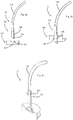
- Fig. 1 shows a schematic representation of a device according to the invention for removing liquid from a container 10 in a schematic representation.
- the device has here a first holding device 2, which serves to hold a first portion 10a of the container.
- This first area of the container 10a is a floor area.
- a second holding device 4 which receives a second region of the container, in particular a mouth region of the container, which also contains the mouth, through which the liquid can be removed from the container. Furthermore, the device has a drive device (not shown in detail), which moves the first holding device relative to the second holding device in the longitudinal direction L of the container.
- the reference numeral 12 indicates the removal device, can be removed by means of the liquid from the container.
- FIGS. 2a-2c show a first embodiment of a removal device 12 according to the invention.
- This removal device 12 in this case has a flow connection body 122, which establishes a flow connection between a hose 124 and the interior of the container.
- the removal device is made of a plastic, which has a greater strength than the closure material.
- the removal device is made of POM (polyoxymethylene), which has a greater strength than an exemplary closure of PP (polypropylene).
- this flow connection body 122 has a cutting element 126, which is tubular and has an oblique cutting edge 125.
- This cutting edge 125 serves to pierce a seal closure 106, which is arranged on a recess 108 of a container closure 100.
- this recess 108 is such designed to receive the flow connection body 122 and the cutting element 126 accurately.
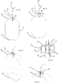
- FIG. 11 shows a situation where the flow communication body 122 has been inserted into the closure 100.
- the cutting edge 125 has pierced the seal 106.
- the seal 106 is not completely separated by the oblique design of the cutting edge 125, but remains in a region on the closure hang so that it does not fall into the liquid.
- Fig. 2c shows a further illustration of the removal device 12.
- a disc-shaped cover member 132 is shown, which also applies when inserting the flow connection body 12 to the closure.
- This lid member 132 also acts as a stop to which the container 10 is brought and on which it rests during removal of the liquid from the container.
- the reference numeral 128 denotes a connection means with which the hose member 124 is arranged on the flow connection body 122.
- the cover element 132 can in turn be supported relative to the second holding device 4 (not shown).
- FIGS. 3a-3e show a further embodiment of the device according to the invention, but here also the container 10 with the first region 10a and the second region 10b is shown.
- the closure 100 has a tubular body 102 which extends into the interior of the container 10.
- Fig. 3b which shows an inserted state of the flow connection body that the piercing means or the cutting element 126 is also introduced into this tubular body 102.
- This tubular body 102 serves to be able to dissipate the liquid as much as possible when the container is squeezed out.
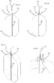
- Fig. 3c shows a perspective view of the in the Fig. 3a and 3d shown device. It can be seen that the closure 100 is screwed onto the mouth of the container here.
- the container 10 also has an external thread 10c onto which the closure, in particular with a circumferential wall 42, is screwed.
- the reference numeral 44 denotes a contact surface to which the cutting element 126, which has the cutting edge 125, applies.
- the reference numeral 48 denotes a recess, by means of which a circumferential pressure can be exerted radially inwardly on the cutting element 126. This shape of the recess can also be used to increase the flow cross-section between the closure 100 and the cutting element 126 during the extraction process.
- Fig. 3e shows a further illustration of a container according to the invention with inserted flow connection body 122 or inserted cutting element 126. It can also be seen here that the cutting element 126 is inserted into the tubular body 102.
- FIGS. 4a-4d show a further embodiment of the present invention.
- the container 10 is squeezed or compressed to empty its contents.
- a gas to additionally be introduced in order to discharge the liquid to be extracted via the tubular body 102, which here functions as a riser.
- a further flow connection between the container 10 and its surroundings could be produced, for example, by introducing a second line into the container, via which the container then a gaseous medium is supplied.
- tubular body 102 is made flexible, but it would also be possible that this is rigid and extends into a lower portion of the container. In this case, it would also be possible for the bottom 10a to be designed in a different way than here in order to ensure that as far as possible all liquid can be detected by the tubular body 102.
- the design of the closure is again similar to that in the FIGS. 3a-3e shown embodiment. Again, the puncture is introduced into a tubular body 102.
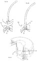
- FIGS. 5a, 5b show a further embodiment of the device according to the invention.
- inserting the flow connection body 12 opens a valve, indicated generally at 70, disposed in the closure 100.
- a flow connection is made to the interior of the container.
- This valve 70 in this case has a valve body 74 which is movable in the longitudinal direction L.
- a valve body 74 which is movable in the longitudinal direction L.
- the valve connecting channels 76 which may extend, for example, in the radial direction, by a peripheral wall 84 which completely surrounds the valve body here in the circumferential direction, circumferentially covered.
- these flow connections 76 are released.
- the reference numeral 82 denotes latching means in which circumferential projections 123 arranged on a flow connection body 122 can be engaged, as in FIG Fig. 5b shown. In this way, upon withdrawal of the flow connection body, the valve 70 can be closed again, or the valve body 74 can be moved upwards.
- Reference numeral 78 denotes a sealant disposed on the valve body 74, which may be an O-ring. In a closed state of the valve 70, this sealant 78 abuts against the peripheral wall 84, thus preventing leakage of liquid between the valve body 74 and the peripheral wall 84.
- Fig. 6 shows a perspective view of the closure with the valve in an open state. Again, it can be seen that the flow connections 76 are released and in this way liquid can be withdrawn through these flow connections upwards.
- a circumferential recess 77 can be seen, which adjoins these flow connections. By this circumferential recess can be increased in an opened state of the valve 70, the flow cross-section for the liquid to be removed.
- the latching means 82 can be seen, which fixes the valve body 74 to the flow connection body 122 in a closed state.
Landscapes
- Containers And Packaging Bodies Having A Special Means To Remove Contents (AREA)
- Apparatus Associated With Microorganisms And Enzymes (AREA)
- Devices For Dispensing Beverages (AREA)
Description
Die vorliegende Erfindung bezieht sich auf eine Vorrichtung zum Entleeren von Behältnissen. Derartige Vorrichtungen sind aus dem Stand der Technik, beispielsweise als Zapfanlagen, bekannt. So zeigen etwa die Druckschriften
Bei derartigen Zapfanlagen tritt das Problem auf, dass deren Bestandteile oftmals sehr schwer zu reinigen sind und auch zum Zwecke der Reinigung viele Chemikalien eingesetzt werden müssen.In such dispensers, the problem arises that their components are often very difficult to clean and also for the purpose of cleaning many chemicals must be used.
Der vorliegenden Erfindung liegt daher die Aufgabe zugrunde, Reinigungsvorgänge für derartige Anlagen einfacher zu gestalten und gegebenenfalls völlig auf diese verzichten zu können.The present invention is therefore based on the object to make cleaning operations for such facilities easier and possibly completely waive this.
Diese Aufgabe wird erfindungsgemäß durch die Gegenstände der unabhängigen Ansprüche erreicht. Vorteilhafte Ausführungsformen und Weiterbildungen sind Gegenstand der Unteransprüche.This object is achieved by the subject of the independent claims. Advantageous embodiments and further developments are the subject of the dependent claims.
Eine erfindungsgemäße Vorrichtung zum Entnehmen von Flüssigkeiten aus verformbaren Behältnissen weist eine erste Halteeinrichtung zum Halten eines ersten Bereichs eines Behältnisses auf sowie eine zweite Halteeinrichtung zum Halten eines zweiten Bereichs des Behältnisses, wobei dieser zweite Bereich von dem ersten Bereich beabstandet ist. Weiterhin weist die Vorrichtung eine Entnahmeeinrichtung auf, um dem Behältnis Flüssigkeit zu entnehmen sowie eine Antriebseinrichtung, welche die zweite Halteeinrichtung bezüglich der ersten Halteeinrichtung in einer vorgegebenen Bewegungsrichtung bewegt.A device according to the invention for removing fluids from deformable containers has a first holding device for holding a first region of a container and a second holding device for holding a second region of the container, this second region being spaced from the first region. Furthermore, the device has a removal device in order to remove liquid from the container, and a drive device which moves the second holding device with respect to the first holding device in a predetermined direction of movement.
Erfindungsgemäß ist die Entnahmeeinrichtung entfernbar an der Vorrichtung angeordnet und wenigstens ein Element der Entnahmeeinrichtung ist als Einwegelement ausgebildet. Vorteilhaft handelt es sich hier bei dem verformbaren Behältnis um ein Kunststoffbehältnis, insbesondere aus PET. Es wäre jedoch auch denkbar, dass das Behältnis aus einem anderen verformbaren Material hergestellt ist.According to the invention, the removal device is removably arranged on the device and at least one element of the removal device is designed as a disposable element. Advantageously, the deformable container is a plastic container, in particular made of PET. However, it would also be conceivable that the container is made of another deformable material.
Es wird daher vorgeschlagen, dass die Entnahmeeinrichtung zumindest teilweise entsorgbar ist bzw. nicht, wie im Stand der Technik üblich, an der Vorrichtung verbleibt. Auf diese Weise kann ein aufwendiger Reinigungsvorgang für diese Entnahmeeinrichtung eingespart werden.It is therefore proposed that the removal device is at least partially disposable or not, as usual in the art, remains on the device. In this way, a complex cleaning process for this removal device can be saved.
Des weiteren besteht während des Entnehmens der Flüssigkeit aus dem Behältnis lediglich eine Strömungsverbindung (d.h. insbesondere ausschließlich nur eine Strömungsverbindung) zwischen dem Innenraum des Behältnisses und einem Außenraum des Behältnisses. Anders als im Stand der Technik üblich, ist daher hier keine weitere Verbindung wie eine weitere Leitung, beispielsweise eine Gasdruckleitung, vorgesehen, sondern lediglich die besagte Flüssigkeitsleitung. Insbesondere handelt es sich bei der besagten einzigen Strömungsverbindung damit um die Flüssigkeitsverbindung, über die dem Behältnis die Flüssigkeit entnommen wird.Further, while the liquid is being withdrawn from the container, there is only flow communication (i.e., in particular, only flow communication only) between the interior of the container and an exterior of the container. Unlike in the conventional art, therefore, no further connection such as a further line, for example a gas pressure line, is provided here, but only the said liquid line. In particular, said single flow connection is the fluid connection via which the liquid is withdrawn from the container.
Bei einer weiteren vorteilhaften Ausführungsform weist die Entnahmeeinrichtung ein flexibles Schlauchelement auf. Bei vielen vergleichbaren Anlagen ist die Entnahmeeinrichtung starr als Rohr ausgebildet und oftmals auch fest in die Vorrichtung integriert. Insbesondere handelt es sich bei diesem Schlauchelement um ein Einweg-Schlauchelement.In a further advantageous embodiment, the removal device has a flexible hose element. In many comparable systems, the removal device is rigidly designed as a tube and often also firmly integrated into the device. In particular, this hose element is a disposable hose element.
Erfindungsgemäss weist die Entnahmeeinrichtung einen Strömungsverbindungskörper auf, der zum Entnehmen der Flüssigkeit wenigstens abschnittsweise in das Behältnis hineinragt. Dabei ist es möglich, dass etwa ein rohrförmiger Körper, der Bestandteil des Strömungsverbindungskörpers ist, der während der Entnahme der Flüssigkeit in diese hineinragt oder zumindest in das Innere des Behältnisses ragt.According to the invention, the removal device has a flow connection body, which protrudes at least in sections into the container for removing the liquid. It is possible that about a tubular body, which is part of the flow connection body, which protrudes into this during the removal of the liquid or at least projects into the interior of the container.
Vorteilhaft schließt sich die Schlauchverbindung an diesen Strömungsverbindungskörper wenigstens mittelbar und bevorzugt unmittelbar an. Dabei ist es möglich, dass das Schlauchelement auf den Strömungsverbindungskörper aufgesteckt ist, es wäre jedoch auch möglich, dass das Schlauchelement mit dem Strömungsverbindungskörper verschraubt ist.Advantageously, the hose connection adjoins this flow connection body at least indirectly and preferably directly. It is possible that the hose member is attached to the flow connection body, but it would also be possible that the hose member is bolted to the flow connection body.
Bei einer weiteren vorteilhaften Ausführungsform ist der Strömungsverbindungskörper als Einstecheinrichtung ausgebildet oder weist eine solche Einstecheinrichtung auf, welche zum Herstellen der Strömungsverbindung mit dem Innenraum des Behältnisses einen Verschluss oder zumindest eine Wandung des Behältnisses durchsticht.In a further advantageous embodiment, the flow connection body is designed as a piercing device or has such a piercing device, which pierces a closure or at least one wall of the container for establishing the flow connection with the interior of the container.
Bei dieser Ausführungsform ist es denkbar, dass beispielsweise mithilfe einer Durchstechnadel der Kunststoffdeckel des Behältnisses bzw. der Verschluss durchstoßen wird und das Medium mittels einer Kunststoffleitung und insbesondere einer Einweg-Kunststoffleitung gezapft wird. Dabei ist vorteilhaft diese Einstechnadel derart ausgebildet, dass ein runder Kreisabschnitt des Deckels aufgrund dieser Ausformung nicht ganz abgerissen wird und damit nicht in die Flüssigkeit fällt. Nach dem vollständigen Entleeren des Behältnisses, der bevorzugt nicht wiederverschlossen werden kann, werden die Einweg-Leitung und das Einstechmittel bzw. die Durchstechnadel entsorgt. Für ein weiteres Behältnis liegt eine neue Leitung, bevorzugt auch ein neues Einstechmittel, bereit. Bevorzugt besteht die Einstecheinrichtung aus einem Kunststoffmaterial, da dadurch eine kostengünstige Herstellung sowie eine einfache Entsorgung nach Verwendung ermöglicht wird. Hierbei weist das Kunststoffmaterial der Einstecheinrichtung bevorzugt insbesondere eine größere Festigkeit auf als das Material des Verschlusses.In this embodiment, it is conceivable that, for example by means of a piercing needle, the plastic lid of the container or the closure is pierced and the medium is tapped by means of a plastic line and in particular a disposable plastic line. In this case, this puncture needle is advantageously designed such that a round circular portion of the lid is not completely demolished due to this formation and thus does not fall into the liquid. After complete emptying of the container, which preferably can not be resealed, the disposable line and the piercing means or the piercing needle are disposed of. For another container is a new line, preferably a new piercing, ready. Preferably, the puncture device consists of a plastic material, since this allows a cost-effective production and easy disposal after use. In this case, the plastic material of the puncture device preferably has in particular a greater strength than the material of the closure.
Bei einer weiteren vorteilhaften Ausführungsform weist die Vorrichtung einen Träger auf, an dem wenigstens eine Halteeinrichtung lösbar angeordnet ist. Vorteilhaft sind jeweils Träger vorgesehen, an denen die beiden Halteeinrichtungen lösbar angeordnet sind, so dass die Vorrichtung auf unterschiedliche Behältnisse angepasst werden kann.In a further advantageous embodiment, the device has a carrier on which at least one holding device is detachably arranged. Carriers are advantageously provided, on which the two holding devices are detachably arranged, so that the device can be adapted to different containers.
Bei einer weiteren vorteilhaften Ausführungsform wäre es auch möglich, dass der Verschluss einen rohrförmigen Körper, beispielsweise in der Art einer Kanüle, aufweist, die das vollständige Entleeren des Behältnisses beim "mechanischen Entleeren", d.h. beim Verformen des Behältnisses ermöglicht. Dieser rohrförmige Körper kann dabei bei einer vollständigen Entleerung den Boden des Behältnisses noch etwas nach unten drücken, um die restliche Flüssigkeit auch zu entleeren. Auch hier ist es bevorzugt vorgesehen, dass das Einstechmittel und der Verschluss entsorgt werden. Allerdings ist hier das Behältnis bevorzugt offen.In a further advantageous embodiment, it would also be possible for the closure to have a tubular body, for example in the manner of a cannula, which facilitates the complete emptying of the container during "mechanical emptying", i. when deforming the container allows. This tubular body can still push down the bottom of the container at a complete emptying, to empty the remaining liquid. Again, it is preferably provided that the puncture means and the closure are disposed of. However, the container is preferably open here.
Die vorliegende Erfindung ist weiterhin auf eine Entnahmeanordnung zum Entnehmen von Flüssigkeiten aus Behältnissen und insbesondere verformbaren Behältnissen gerichtet, welche eine Vorrichtung zum Entnehmen von Flüssigkeiten aufweist, die wiederum eine erste Halteeinrichtung zum Halten eines ersten Bereichs des Behältnisses und eine zweite Halteeinrichtung zum Halten eines zweiten Bereichs des Behältnisses aufweist, wobei der zweite Bereich von dem ersten Bereich beabstandet ist. Weiterhin weist die Entnahmeanordnung eine Entnahmeeinrichtung auf, um dem Behältnis Flüssigkeit zu entnehmen.The present invention is further directed to a dispensing assembly for dispensing liquids from containers, and in particular deformable containers, having a liquid dispensing device which in turn comprises a first holding means for holding a first portion of the container and a second holding means for holding a second portion of the container, wherein the second region is spaced from the first region. Furthermore, the removal arrangement on a removal device to remove the container liquid.
Erfindungsgemäß weist hier das Behältnis einen Verschluss auf, an den sich im Inneren des Behältnisses ein rohrförmiger Körper zum Entnehmen der Flüssigkeit anschließt. Bei diesem rohrförmigen Körper kann es sich beispielsweise um einen Schlauch handeln, der bis zu einem Boden des Behältnisses reicht. Es kann sich jedoch auch um ein festes Rohr handeln, wobei bevorzugt bei dieser Ausgestaltung das Behältnis während des Entnahmevorgangs nicht komprimiert bzw. verformt wird. Vorteilhaft ist - insbesondere an dem Verschluss - ein Siegelelement vorgesehen, welches diesen sich im Inneren des Behältnisses erstreckenden Rohrkörper verschließt. Vorteilhaft fungiert dieser rohrförmige Körper als Steigrohr für die Flüssigkeit, insbesondere, wenn diese entnommen wird oder wenn aufgrund eines zugeführten Drucks die Flüssigkeit aus dem Behältnis gedrängt wird.According to the invention, the container here has a closure, which is followed by a tubular body for removing the liquid inside the container. This tubular body may be, for example, a hose that extends to a bottom of the container. However, it may also be a fixed tube, wherein preferably in this embodiment, the container is not compressed or deformed during the removal process. It is advantageous - in particular on the closure - provided a sealing element which closes this extending inside the container tubular body. Advantageously, this tubular body acts as a riser for the liquid, especially when it is removed or if due to a supplied pressure, the liquid is forced out of the container.
Damit wird hier mittels eines Rohres bzw. einer langen Kanüle, die bevorzugt fast bis zum Behältnisboden reicht, das Medium entleert, wobei hier insbesondere auch eine zusätzliche Gaszufuhr erfolgen kann. Durch die Zufuhr von Gas steigt der Druck in dem Behältnis und das Medium wird über die besagte Kanüle entleert. Das Durchstechen erfolgt wie in der oben beschriebenen Art mithilfe eines Einstechkörpers. Im Unterschied zu der oben beschriebenen Ausführungsform besteht daher hier eine weitere Strömungsverbindung zwischen dem Innenraum des Behältnisses und dessen Außenraum, insbesondere in Form der Gasverbindung.Thus, the medium is emptied here by means of a tube or a long cannula, which preferably extends almost to the container bottom, in which case, in particular, an additional gas supply can take place. The supply of gas increases the pressure in the container and the medium is emptied through said cannula. The piercing is carried out as in the manner described above using a piercing body. In contrast to the embodiment described above, therefore, there is a further flow connection between the Interior of the container and its outer space, in particular in the form of the gas connection.
Vorteilhaft ist die Entnahmeeinrichtung entfernbar an der Vorrichtung angeordnet und wenigstens ein Element der Entnahmeeinrichtung ist als Einwegelement ausgebildet. Daher wird auch bei dieser Ausgestaltung vorgeschlagen, dass die Entnahmeeinrichtung Einweg-Komponenten aufweist. Daher werden auch hier bevorzugt nach jedem Wechsel des Behältnisses die Schlauchleitung und bevorzugt auch die Durchstechnadel bzw. das Einstechmittel gewechselt.Advantageously, the removal device is removably disposed on the device and at least one element of the removal device is formed as a disposable element. Therefore, it is also proposed in this embodiment that the removal device comprises disposable components. Therefore, also here preferably after each change of the container, the hose and preferably also the piercing needle or the piercing means are changed.
Bei einer weiteren vorteilhaften Ausführungsform weist die Entnahmeeinrichtung einen Strömungsverbindungskörper auf, der wenigstens abschnittsweise in den rohrförmigen Körper einführbar ist. Bei dieser Ausführungsform ist - wie gesagt - bevorzugt wieder ein Einstechmittel vorgesehen, welches jedoch hinsichtlich seines Querschnitts derart an den rohrförmigen Körper angepasst ist, dass es auch in diesen rohrförmigen Körper im Inneren des Behältnisses eingeführt werden kann.In a further advantageous embodiment, the removal device has a flow connection body, which is at least partially insertable into the tubular body. In this embodiment - as mentioned - preferably again a piercing means is provided, which, however, adapted in terms of its cross-section to the tubular body so that it can also be introduced into this tubular body in the interior of the container.
Bei einer weiteren vorteilhaften Ausführungsform weist der Verschluss des Behältnisses eine Ventileinrichtung auf. Vorteilhaft wird diese Ventileinrichtung durch eine Bewegung der Entnahmeeinrichtung und insbesondere eines Einsetzens bzw. Einführens der Entnahmeeinrichtung bzw. des Strömungsverbindungskörpers geöffnet. Dies wird unten unter Bezugnahme auf die Figuren genauer beschrieben. So ist es beispielsweise möglich, dass das Behältnis durch das Ventil mit einer eingesetzten Dichtung verschlossen ist und bevorzugt bereits über dieses Ventil befüllt wird. Weiterhin kann beispielsweise durch eine spezielle Ausprägung in dem Füllstempel, bzw. der Entnahmeeinrichtung nach dem vollständigen Befüllen das Ventil automatisch mit nach oben gezogen und somit geschlossen werden.In a further advantageous embodiment, the closure of the container has a valve device. Advantageously, this valve device is opened by a movement of the removal device and in particular an insertion or insertion of the removal device or the flow connection body. This will be described in more detail below with reference to the figures. For example, it is possible that the container is closed by the valve with an inserted seal and is preferably already filled via this valve. Furthermore, for example, by a special expression in the Füllstempel, or the removal device after the complete filling, the valve automatically pulled up with and thus closed.
Bei einem Entleervorgang wird das Ventil durch eine Entnahmeeinrichtung bzw. einem Stempel, an dem die Einwegleitung angeschlossen ist, nach unten geschoben und das Behältnis kann entleert werden. Bevorzugt ist auch hier die Entnahmeeinrichtung als Einwegelement ausgebildet und kann nach dem vollständigen Entleeren des Behältnisses entsorgt werden. Es wäre jedoch auch denkbar, dass das Ventil vor dem vollständigen Entleeren des Behältnisses wieder geschlossen wird.In an emptying operation, the valve is pushed by a removal device or a stamp to which the disposable line is connected, down and the container can be emptied. Preferably, the removal device is also designed as a disposable element and can be disposed of after complete emptying of the container. However, it would also be conceivable that the valve is closed again before the container is completely emptied.
Bei einer weiteren Ausführungsform wäre es auch möglich, dass der Behältnisverschluss zwei in der Einstechrichtung übereinander angeordnete Verschlusselemente aufweist. Dabei ist es möglich, dass die beiden Verschlusselemente jeweils Öffnungen aufweisen, die auf diese Weise in der Längsrichtung des Behältnisses zueinander versetzt sind.In a further embodiment, it would also be possible for the container closure to have two closure elements arranged one above the other in the piercing direction. It is possible that the two closure elements each have openings which are offset in this way in the longitudinal direction of the container to each other.
Bei einer weiteren bevorzugten Ausführungsform wäre es möglich, dass das Ventil in dem Behältnisverschluss als Rückschlagventil ausgebildet ist, welches bevorzugt automatisch schließt, wenn keine Entnahmeeinrichtung eingesetzt ist. Bei einer weiteren vorteilhaften Ausführungsform weist der Verschluss wenigstens ein Element auf, welches gegenüber einem anderen Element des Verschlusses beweglich ist und insbesondere auch in einer Längsrichtung des Behältnisses bzw. einer Einstechrichtung des Einstechelements beweglich ist.In a further preferred embodiment, it would be possible that the valve is formed in the container closure as a check valve, which preferably closes automatically when no removal device is used. In a further advantageous embodiment, the closure has at least one element which is movable relative to another element of the closure and in particular is also movable in a longitudinal direction of the container or a piercing direction of the puncturing element.
Bei einer weiteren vorteilhaften Ausführungsform weist der Verschluss auch ein Federungselement auf, welches das Ventil in eine geschlossene bzw. eine geöffnete Stellung, bevorzugt jedoch in geschlossene Stellung, drängt. Dabei kann es sich um eine Federungseinrichtung handeln, welche aus einem Kunststoff besteht. Bei einer weiteren vorteilhaften Ausführungsform weist der Verschluss ein durchstoßbares und insbesondere folienartiges Element auf.In a further advantageous embodiment, the closure also has a suspension element, which urges the valve in a closed or an open position, but preferably in the closed position. It may be a suspension device, which consists of a plastic. In a further advantageous embodiment, the closure has a pierceable and in particular a film-like element.
Weitere Vorteile und Ausführungsformen ergeben sich aus den beigefügten Zeichnungen:Further advantages and embodiments will be apparent from the attached drawings:
Darin zeigen:
- Fig. 1
- Eine schematische Darstellung einer erfindungsgemäßen Vorrichtung;
- Fig. 2a-2c
- drei Darstellungen einer erfindungsgemäßen Vorrichtung in einer ersten Ausführungsform;
- Fig. 3a-3e
- fünf Darstellungen einer erfindungsgemäßen Vorrichtung in einer zweiten Ausführungsform;
- Fig. 4a-4d
- vier Darstellungen einer erfindungsgemäßen Vorrichtung in einer dritten Ausführungsform;
- Fig. 5a, 5b
- zwei Darstellungen einer erfindungsgemäßen Vorrichtung in einer vierten Ausführungsform; und
- Fig. 6
- eine Darstellung eines Verschlusses mit Ventileinrichtung.
- Fig. 1
- A schematic representation of a device according to the invention;
- Fig. 2a-2c
- three representations of a device according to the invention in a first embodiment;
- Fig. 3a-3e
- five illustrations of a device according to the invention in a second embodiment;
- Fig. 4a-4d
- four illustrations of a device according to the invention in a third embodiment;
- Fig. 5a, 5b
- two representations of a device according to the invention in a fourth embodiment; and
- Fig. 6
- a representation of a closure with valve device.
Weiterhin ist eine zweite Halteeinrichtung 4 vorgesehen, welche einen zweiten Bereich des Behältnisses aufnimmt, hier insbesondere einen Mündungsbereich des Behältnisses, der auch die Mündung enthält, über welche die Flüssigkeit aus dem Behältnis entnommen werden kann. Weiterhin weist die Vorrichtung eine (nicht im Detail gezeigte) Antriebseinrichtung auf, welche die erste Halteeinrichtung gegenüber der zweiten Halteeinrichtung in der Längsrichtung L des Behältnisses bewegt. Das Bezugszeichen 12 kennzeichnet die Entnahmeeinrichtung, mittels der Flüssigkeit aus dem Behältnis entnommen werden kann.Furthermore, a second holding device 4 is provided which receives a second region of the container, in particular a mouth region of the container, which also contains the mouth, through which the liquid can be removed from the container. Furthermore, the device has a drive device (not shown in detail), which moves the first holding device relative to the second holding device in the longitudinal direction L of the container. The
Dieser Strömungsverbindungskörper 122 weist hier ein Schneidelement 126 auf, welches rohrförmig ausgebildet ist und eine schräge Schneidkante 125 aufweist. Diese Schneidkante 125 dient zum Durchstoßen eines Siegelverschlusses 106, der an einer Ausnehmung 108 eines Behältnisverschlusses 100 angeordnet ist. Dabei ist diese Ausnehmung 108 derart ausgebildet, dass sie den Strömungsverbindungskörper 122 bzw. das Schneidelement 126 passgenau aufnimmt.Here, this
Die
Bei der in
Die
Dabei ist es möglich, dass der rohrförmige Körper 102 flexibel ausgeführt ist, es wäre jedoch auch möglich, dass dieser starr ausgebildet ist und bis in einen unteren Bereich des Behältnisses reicht. Dabei wäre es auch möglich, dass der Boden 10a in anderer Weise als hier ausgeführt ist, um zu erreichen, dass möglichst sämtliche Flüssigkeit von dem rohrförmigen Körper 102 erfasst werden kann.It is possible that the
Die Gestaltung des Verschlusses ähnelt wiederum der in den
Die
Dieses Ventil 70 weist dabei einen in der Längsrichtung L beweglichen Ventilkörper 74 auf. In einem geschlossenen Zustand des Ventils sind Verbindungskanäle 76, die beispielsweise in radialer Richtung verlaufen können, durch eine Umfangswandung 84, welche den Ventilkörper hier in dessen Umfangsrichtung vollständig umgibt, umfänglich verdeckt. Bei der in
Das Bezugszeichen 82 kennzeichnet Einrastmittel, in welche umlaufende Vorsprünge 123, die an einem Strömungsverbindungskörper 122 angeordnet sind, einrasten können, wie in
Auch ist hier das Einrastmittel 82 erkennbar, welches in einem geschlossenen Zustand den Ventilkörper 74 an dem Strömungsverbindungskörper 122 fixiert.Also here, the latching means 82 can be seen, which fixes the
Die Anmelderin behält sich vor, sämtliche in den Anmeldungsunterlagen offenbarten Merkmale als erfindungswesentlich zu beanspruchen, sofern sie einzeln oder in Kombination gegenüber dem Stand der Technik neu sind.The Applicant reserves the right to claim all features disclosed in the application documents as essential to the invention, provided they are novel individually or in combination with respect to the prior art.
- 11
- Vorrichtungcontraption
- 22
- erste Halteeinrichtungfirst holding device
- 44
- zweite Halteeinrichtungsecond holding device
- 1010
- Behältniscontainer
- 10a10a
- Bodenbereich des BehältnissesBottom area of the container
- 10b10b
- zweiter Behältnisbereichsecond container area
- 1212
- Entnahmeeinrichtungremoval device
- 4242
-
Umfangswandung des Verschlusses 100Peripheral wall of the
closure 100 - 4444
- Anliegeflächebearing surface
- 4848
- Ausnehmungrecess
- 7070
- VentilValve
- 7474
- Ventilkörpervalve body
- 7676
- Verbindungskanäleconnecting channels
- 7777
- Ausnehmungrecess
- 8282
- Einrastmittellatching
- 8484
- Umfangswandungperipheral
- 100100
- Behältnisverschlusscontainer closure
- 102102
- rohrförmiger Körpertubular body
- 106106
- Siegelverschlussseal closure
- 108108
- Ausnehmungrecess
- 122122
- StrömungsverbindungskörperFlow connection body
- 123123
- Vorsprüngeprojections
- 124124
- Schlauchtube
- 125125
- Schneidkantecutting edge
- 126126
- Schneidelementcutting element
- 128128
- Verbindungseinrichtungconnecting device
- 132132
- Deckelelementcover element
- LL
- Längsrichtunglongitudinal direction
Claims (9)
- An apparatus (1) for the removal of liquids from deformable containers (10), with a first holding device (2) for holding a first region (10a) of a container (10) and with a second holding device (4) for holding a second region (10b) of the container (10), wherein this second region (10b) is arranged at a distance from the first region (10a), with a removal device (12) for removing liquid from the container and with a drive device (8) which moves the second holding device (4) in a pre-set direction of movement (L) with respect to the first holding device (2),
characterised in that
the removal device (12) is arranged on the apparatus (1) in a removable manner and at least one element of the removal device (12) is designed in the form of a one-way element wherein the removal device (12) has a flow connection body (122) which projects at least locally into the container (10) in order to remove the liquid.. - An apparatus (1) according to claim 1,
characterised in that
only one flow connection is present between the interior of the container (10) and an external space of the container (10) during the removal of the liquid from the container (10). - An apparatus (1) according to at least one of the preceding claims
characterised in that
the removal device (12) has a flexible hose element (124). - An apparatus (1) according at least one of the preceding claims
characterised in that
the flexible hose element (124) is attached to the flow connection body (122). - An apparatus (1)according to claim 4
characterised in that
the flow connection body (122) is designed in the form of a piercing device, which in order to produce the flow connection with the interior of the container (10) pierces a closure (100) or at least a wall of the container (10). - A removal arrangement for the removal of liquids from containers (10) with an apparatus (1) for the removal of liquids according to claim 1, which has a first holding device (2) for holding a first region (10a) of a container (10), and a second holding device (4) for holding a second region (10b) of the container (10), wherein this second region (10b) is arranged at a distance from the first region (10a), and with a removal device (12) for removing liquid from the container,
Characterised in that
the container has a closure (100) to which a tubular body (102) for the removal of liquid is attached in the interior of the container. - A removal arrangement according to claim 6,
characterised in that
the removal device (12) is arranged on the apparatus (1) in a removable manner and at least one element of the removal device (12) is designed in the form of a one-way element. - A removal arrangement according to claim 6,
characterised in that
the removal device (12) has a flow connection body (122) which is capable of being inserted into the tubular body (102). - A removal arrangement according to claim 6,
characterised in that
the closure (100) of the container (10) has a valve device (70).
Applications Claiming Priority (2)
| Application Number | Priority Date | Filing Date | Title |
|---|---|---|---|
| DE102012111850.7A DE102012111850A1 (en) | 2012-12-05 | 2012-12-05 | Device for emptying containers |
| PCT/EP2013/075650 WO2014086920A1 (en) | 2012-12-05 | 2013-12-05 | Apparatus for emptying containers |
Publications (2)
| Publication Number | Publication Date |
|---|---|
| EP2928811A1 EP2928811A1 (en) | 2015-10-14 |
| EP2928811B1 true EP2928811B1 (en) | 2018-10-24 |
Family
ID=49885203
Family Applications (1)
| Application Number | Title | Priority Date | Filing Date |
|---|---|---|---|
| EP13814463.9A Not-in-force EP2928811B1 (en) | 2012-12-05 | 2013-12-05 | Apparatus for emptying containers |
Country Status (7)
| Country | Link |
|---|---|
| US (1) | US9546084B2 (en) |
| EP (1) | EP2928811B1 (en) |
| CN (1) | CN103998369B (en) |
| BR (1) | BR112015012952A2 (en) |
| DE (1) | DE102012111850A1 (en) |
| RU (1) | RU2652950C2 (en) |
| WO (1) | WO2014086920A1 (en) |
Families Citing this family (6)
| Publication number | Priority date | Publication date | Assignee | Title |
|---|---|---|---|---|
| DE102013110121A1 (en) * | 2013-09-13 | 2015-03-19 | Krones Ag | Disposable emptying system for containers |
| DE102014113915A1 (en) * | 2014-09-25 | 2016-03-31 | Krones Aktiengesellschaft | Compressible plastic container with ground cup |
| DE102014115891A1 (en) * | 2014-10-31 | 2016-05-04 | Krones Aktiengesellschaft | Closure, in particular plastic closure for a container |
| DE102015008314A1 (en) * | 2015-06-30 | 2017-01-05 | Krones Ag | Treatment machine for treating containers and / or food with supply of a working medium |
| AU2018231368B2 (en) * | 2017-03-10 | 2023-10-26 | Carlsberg Breweries A/S | A beverage dispensing system, a beverage dispensing assembly, a method of operating a beverage dispensing system and a pressure housing |
| CN108313965A (en) * | 2018-02-28 | 2018-07-24 | 广西玉柴机器股份有限公司 | A kind of automatic real-time pumping equipment |
Family Cites Families (21)
| Publication number | Priority date | Publication date | Assignee | Title |
|---|---|---|---|---|
| US1880354A (en) * | 1931-07-30 | 1932-10-04 | Herman C Mueller | Fluid gun |
| NL1015411C2 (en) * | 2000-06-09 | 2001-12-14 | Heineken Tech Services | Beverage container provided with a chamber with a flexible dispensing line and with positioning means. |
| US4136801A (en) * | 1977-12-09 | 1979-01-30 | Stanford Pavenick | Replaceable cartridge for a dispenser |
| US4375864A (en) * | 1980-07-21 | 1983-03-08 | Scholle Corporation | Container for holding and dispensing fluid |
| US4456134A (en) * | 1982-01-22 | 1984-06-26 | Leonard Cooper | Apparatus for containment of carbonated beverages |
| CA1195666A (en) * | 1982-12-16 | 1985-10-22 | Glen C. Bull, Jr. | Methods of dispensing beverages with self-dispensing spring biased thin film containers |
| DE3618634A1 (en) * | 1986-06-03 | 1987-12-10 | Jean Pierre Denis | DISPENSER FOR BEVERAGES |
| US5206037A (en) * | 1990-08-31 | 1993-04-27 | Robbins Edward S Iii | Apparatus for collapsing a container |
| US5139169A (en) * | 1991-02-21 | 1992-08-18 | Boyer Richard L | Carbonated beverage dispensing system |
| SE502095C2 (en) * | 1993-10-18 | 1995-08-14 | Asept Int Ab | Device for dispensing of viscous material from a package |
| US5505336A (en) * | 1994-02-14 | 1996-04-09 | The Diggs Group | Ice cream dispenser |
| EP1621514B1 (en) * | 1997-09-04 | 2010-04-21 | Heineken Supply Chain B.V. | Beverage dispensing apparatus |
| AUPQ450999A0 (en) * | 1999-12-07 | 2000-01-06 | Perna Pty Ltd | Storage and dispensing of carbonated beverages |
| NL1020492C2 (en) * | 2002-04-26 | 2003-10-28 | Well Design Associates B V | Compression of holders. |
| US20060186136A1 (en) * | 2002-11-29 | 2006-08-24 | Albert Wauters | Beer dispensing apparatus |
| GB0411294D0 (en) * | 2004-05-20 | 2004-06-23 | Interbrew Sa | Keg tap adapter with flow restriction |
| US9725293B2 (en) * | 2005-11-29 | 2017-08-08 | Petainer Lidkoping Ab | System and method for distribution and dispensing of beverages |
| GB2436828A (en) * | 2006-04-07 | 2007-10-10 | Marios Josephidou | Dispensing system for retaining carbonation |
| NL1035761C2 (en) * | 2008-07-28 | 2010-02-05 | Dispensing Technologies Bv | Method and device for metered dispensing of a liquid from a container. |
| CN102666362B (en) * | 2009-11-23 | 2015-03-11 | 嘉士伯酿酒有限公司 | A system for rapid contact cooling of a collapsible beverage container in a beverage dispensing system |
| US9534831B2 (en) * | 2010-10-29 | 2017-01-03 | Whirlpool Corporation | Liquid dispenser with collapsible container |
-
2012
- 2012-12-05 DE DE102012111850.7A patent/DE102012111850A1/en not_active Withdrawn
-
2013
- 2013-12-05 CN CN201380001675.1A patent/CN103998369B/en not_active Expired - Fee Related
- 2013-12-05 WO PCT/EP2013/075650 patent/WO2014086920A1/en not_active Ceased
- 2013-12-05 BR BR112015012952A patent/BR112015012952A2/en not_active IP Right Cessation
- 2013-12-05 US US14/650,223 patent/US9546084B2/en not_active Expired - Fee Related
- 2013-12-05 RU RU2015119378A patent/RU2652950C2/en not_active IP Right Cessation
- 2013-12-05 EP EP13814463.9A patent/EP2928811B1/en not_active Not-in-force
Also Published As
| Publication number | Publication date |
|---|---|
| EP2928811A1 (en) | 2015-10-14 |
| CN103998369A (en) | 2014-08-20 |
| BR112015012952A2 (en) | 2017-07-11 |
| CN103998369B (en) | 2018-04-10 |
| RU2652950C2 (en) | 2018-05-03 |
| RU2015119378A (en) | 2017-01-11 |
| DE102012111850A1 (en) | 2014-06-05 |
| WO2014086920A1 (en) | 2014-06-12 |
| US20150344280A1 (en) | 2015-12-03 |
| US9546084B2 (en) | 2017-01-17 |
Similar Documents
| Publication | Publication Date | Title |
|---|---|---|
| EP2928811B1 (en) | Apparatus for emptying containers | |
| EP1140259B1 (en) | Multi-chambered ampoule for dispensing a mixture comprising several substances | |
| EP2985015A1 (en) | Syringe adapter | |
| DE102015201285B3 (en) | Device for transferring a liquid between a storage container and at least one further use container and set of transfer device and storage container | |
| DE102007046625A1 (en) | Device for separately storing and mixing a substance, preferably a medicinal or pharmaceutical active substance, and a liquid | |
| EP2723648B1 (en) | Device for receiving and dispensing a fluid | |
| EP2447485A1 (en) | Container for lubricant and bearing assembly with same | |
| EP2520360A1 (en) | Mixer for mixing at least two flowing components and application device | |
| EP2817257B1 (en) | Removal device for removing liquids from containers | |
| DE102015118053A1 (en) | Closure device for a container | |
| EP3308682B1 (en) | Reusable capsule for preparing beverages and filling device for filling such a reusable capsule and method for the preparation of beverages with such a reusable capsule using a capsule beverage machine | |
| WO2014086931A1 (en) | Apparatus for removing liquids from containers | |
| EP3250173B1 (en) | Hollow needle assembly | |
| DE102011086278A1 (en) | Emptying and emptying device for a contamination-free emptying of an at least partially flexible container | |
| WO2015036573A1 (en) | One-way drainage system for liquid containers | |
| EP2731477B1 (en) | Process for extracting an ingredient of a portion capsule | |
| EP2905041A1 (en) | Syringe | |
| EP3972460B1 (en) | Brewing apparatus and method for operating a brewing apparatus | |
| EP3652083B1 (en) | Container closure with a standard capsule | |
| EP3250172B1 (en) | Device for transferring a fluid between a storage container and at least one further container for use | |
| EP2886474B1 (en) | Device for contamination-free packing of products in tubular bags, and use of the device | |
| AT396058B (en) | Device for transferring sterile fluids in a closed system | |
| EP4234419A1 (en) | Filling device, sampler connection device with such a filling device and corresponding method | |
| EP4501368A1 (en) | Device for filling blood products | |
| DE102005012412A1 (en) | Cap including opening and resealing mechanisms for container which assures e.g. contents authentication and tamper proofing, includes penetrating component and sealing surface |
Legal Events
| Date | Code | Title | Description |
|---|---|---|---|
| PUAI | Public reference made under article 153(3) epc to a published international application that has entered the european phase |
Free format text: ORIGINAL CODE: 0009012 |
|
| 17P | Request for examination filed |
Effective date: 20150617 |
|
| AK | Designated contracting states |
Kind code of ref document: A1 Designated state(s): AL AT BE BG CH CY CZ DE DK EE ES FI FR GB GR HR HU IE IS IT LI LT LU LV MC MK MT NL NO PL PT RO RS SE SI SK SM TR |
|
| AX | Request for extension of the european patent |
Extension state: BA ME |
|
| DAX | Request for extension of the european patent (deleted) | ||
| 17Q | First examination report despatched |
Effective date: 20180214 |
|
| GRAP | Despatch of communication of intention to grant a patent |
Free format text: ORIGINAL CODE: EPIDOSNIGR1 |
|
| INTG | Intention to grant announced |
Effective date: 20180507 |
|
| GRAS | Grant fee paid |
Free format text: ORIGINAL CODE: EPIDOSNIGR3 |
|
| GRAA | (expected) grant |
Free format text: ORIGINAL CODE: 0009210 |
|
| AK | Designated contracting states |
Kind code of ref document: B1 Designated state(s): AL AT BE BG CH CY CZ DE DK EE ES FI FR GB GR HR HU IE IS IT LI LT LU LV MC MK MT NL NO PL PT RO RS SE SI SK SM TR |
|
| REG | Reference to a national code |
Ref country code: CH Ref legal event code: EP |
|
| REG | Reference to a national code |
Ref country code: IE Ref legal event code: FG4D Free format text: LANGUAGE OF EP DOCUMENT: GERMAN |
|
| REG | Reference to a national code |
Ref country code: AT Ref legal event code: REF Ref document number: 1056434 Country of ref document: AT Kind code of ref document: T Effective date: 20181115 |
|
| REG | Reference to a national code |
Ref country code: DE Ref legal event code: R096 Ref document number: 502013011446 Country of ref document: DE |
|
| REG | Reference to a national code |
Ref country code: NL Ref legal event code: MP Effective date: 20181024 |
|
| REG | Reference to a national code |
Ref country code: LT Ref legal event code: MG4D |
|
| PG25 | Lapsed in a contracting state [announced via postgrant information from national office to epo] |
Ref country code: NL Free format text: LAPSE BECAUSE OF FAILURE TO SUBMIT A TRANSLATION OF THE DESCRIPTION OR TO PAY THE FEE WITHIN THE PRESCRIBED TIME-LIMIT Effective date: 20181024 |
|
| PG25 | Lapsed in a contracting state [announced via postgrant information from national office to epo] |
Ref country code: FI Free format text: LAPSE BECAUSE OF FAILURE TO SUBMIT A TRANSLATION OF THE DESCRIPTION OR TO PAY THE FEE WITHIN THE PRESCRIBED TIME-LIMIT Effective date: 20181024 Ref country code: LV Free format text: LAPSE BECAUSE OF FAILURE TO SUBMIT A TRANSLATION OF THE DESCRIPTION OR TO PAY THE FEE WITHIN THE PRESCRIBED TIME-LIMIT Effective date: 20181024 Ref country code: PL Free format text: LAPSE BECAUSE OF FAILURE TO SUBMIT A TRANSLATION OF THE DESCRIPTION OR TO PAY THE FEE WITHIN THE PRESCRIBED TIME-LIMIT Effective date: 20181024 Ref country code: HR Free format text: LAPSE BECAUSE OF FAILURE TO SUBMIT A TRANSLATION OF THE DESCRIPTION OR TO PAY THE FEE WITHIN THE PRESCRIBED TIME-LIMIT Effective date: 20181024 Ref country code: BG Free format text: LAPSE BECAUSE OF FAILURE TO SUBMIT A TRANSLATION OF THE DESCRIPTION OR TO PAY THE FEE WITHIN THE PRESCRIBED TIME-LIMIT Effective date: 20190124 Ref country code: ES Free format text: LAPSE BECAUSE OF FAILURE TO SUBMIT A TRANSLATION OF THE DESCRIPTION OR TO PAY THE FEE WITHIN THE PRESCRIBED TIME-LIMIT Effective date: 20181024 Ref country code: LT Free format text: LAPSE BECAUSE OF FAILURE TO SUBMIT A TRANSLATION OF THE DESCRIPTION OR TO PAY THE FEE WITHIN THE PRESCRIBED TIME-LIMIT Effective date: 20181024 Ref country code: IS Free format text: LAPSE BECAUSE OF FAILURE TO SUBMIT A TRANSLATION OF THE DESCRIPTION OR TO PAY THE FEE WITHIN THE PRESCRIBED TIME-LIMIT Effective date: 20190224 Ref country code: NO Free format text: LAPSE BECAUSE OF FAILURE TO SUBMIT A TRANSLATION OF THE DESCRIPTION OR TO PAY THE FEE WITHIN THE PRESCRIBED TIME-LIMIT Effective date: 20190124 |
|
| PG25 | Lapsed in a contracting state [announced via postgrant information from national office to epo] |
Ref country code: AL Free format text: LAPSE BECAUSE OF FAILURE TO SUBMIT A TRANSLATION OF THE DESCRIPTION OR TO PAY THE FEE WITHIN THE PRESCRIBED TIME-LIMIT Effective date: 20181024 Ref country code: PT Free format text: LAPSE BECAUSE OF FAILURE TO SUBMIT A TRANSLATION OF THE DESCRIPTION OR TO PAY THE FEE WITHIN THE PRESCRIBED TIME-LIMIT Effective date: 20190224 Ref country code: GR Free format text: LAPSE BECAUSE OF FAILURE TO SUBMIT A TRANSLATION OF THE DESCRIPTION OR TO PAY THE FEE WITHIN THE PRESCRIBED TIME-LIMIT Effective date: 20190125 Ref country code: SE Free format text: LAPSE BECAUSE OF FAILURE TO SUBMIT A TRANSLATION OF THE DESCRIPTION OR TO PAY THE FEE WITHIN THE PRESCRIBED TIME-LIMIT Effective date: 20181024 Ref country code: RS Free format text: LAPSE BECAUSE OF FAILURE TO SUBMIT A TRANSLATION OF THE DESCRIPTION OR TO PAY THE FEE WITHIN THE PRESCRIBED TIME-LIMIT Effective date: 20181024 |
|
| REG | Reference to a national code |
Ref country code: DE Ref legal event code: R119 Ref document number: 502013011446 Country of ref document: DE |
|
| PG25 | Lapsed in a contracting state [announced via postgrant information from national office to epo] |
Ref country code: IT Free format text: LAPSE BECAUSE OF FAILURE TO SUBMIT A TRANSLATION OF THE DESCRIPTION OR TO PAY THE FEE WITHIN THE PRESCRIBED TIME-LIMIT Effective date: 20181024 Ref country code: CZ Free format text: LAPSE BECAUSE OF FAILURE TO SUBMIT A TRANSLATION OF THE DESCRIPTION OR TO PAY THE FEE WITHIN THE PRESCRIBED TIME-LIMIT Effective date: 20181024 Ref country code: DK Free format text: LAPSE BECAUSE OF FAILURE TO SUBMIT A TRANSLATION OF THE DESCRIPTION OR TO PAY THE FEE WITHIN THE PRESCRIBED TIME-LIMIT Effective date: 20181024 |
|
| REG | Reference to a national code |
Ref country code: CH Ref legal event code: PL |
|
| PG25 | Lapsed in a contracting state [announced via postgrant information from national office to epo] |
Ref country code: SM Free format text: LAPSE BECAUSE OF FAILURE TO SUBMIT A TRANSLATION OF THE DESCRIPTION OR TO PAY THE FEE WITHIN THE PRESCRIBED TIME-LIMIT Effective date: 20181024 Ref country code: EE Free format text: LAPSE BECAUSE OF FAILURE TO SUBMIT A TRANSLATION OF THE DESCRIPTION OR TO PAY THE FEE WITHIN THE PRESCRIBED TIME-LIMIT Effective date: 20181024 Ref country code: MC Free format text: LAPSE BECAUSE OF FAILURE TO SUBMIT A TRANSLATION OF THE DESCRIPTION OR TO PAY THE FEE WITHIN THE PRESCRIBED TIME-LIMIT Effective date: 20181024 Ref country code: SK Free format text: LAPSE BECAUSE OF FAILURE TO SUBMIT A TRANSLATION OF THE DESCRIPTION OR TO PAY THE FEE WITHIN THE PRESCRIBED TIME-LIMIT Effective date: 20181024 Ref country code: LU Free format text: LAPSE BECAUSE OF NON-PAYMENT OF DUE FEES Effective date: 20181205 Ref country code: RO Free format text: LAPSE BECAUSE OF FAILURE TO SUBMIT A TRANSLATION OF THE DESCRIPTION OR TO PAY THE FEE WITHIN THE PRESCRIBED TIME-LIMIT Effective date: 20181024 |
|
| PLBE | No opposition filed within time limit |
Free format text: ORIGINAL CODE: 0009261 |
|
| STAA | Information on the status of an ep patent application or granted ep patent |
Free format text: STATUS: NO OPPOSITION FILED WITHIN TIME LIMIT |
|
| REG | Reference to a national code |
Ref country code: IE Ref legal event code: MM4A |
|
| GBPC | Gb: european patent ceased through non-payment of renewal fee |
Effective date: 20190124 |
|
| 26N | No opposition filed |
Effective date: 20190725 |
|
| REG | Reference to a national code |
Ref country code: BE Ref legal event code: MM Effective date: 20181231 |
|
| PG25 | Lapsed in a contracting state [announced via postgrant information from national office to epo] |
Ref country code: DE Free format text: LAPSE BECAUSE OF NON-PAYMENT OF DUE FEES Effective date: 20190702 Ref country code: IE Free format text: LAPSE BECAUSE OF NON-PAYMENT OF DUE FEES Effective date: 20181205 Ref country code: FR Free format text: LAPSE BECAUSE OF NON-PAYMENT OF DUE FEES Effective date: 20181224 Ref country code: SI Free format text: LAPSE BECAUSE OF FAILURE TO SUBMIT A TRANSLATION OF THE DESCRIPTION OR TO PAY THE FEE WITHIN THE PRESCRIBED TIME-LIMIT Effective date: 20181024 |
|
| PG25 | Lapsed in a contracting state [announced via postgrant information from national office to epo] |
Ref country code: BE Free format text: LAPSE BECAUSE OF NON-PAYMENT OF DUE FEES Effective date: 20181231 |
|
| PG25 | Lapsed in a contracting state [announced via postgrant information from national office to epo] |
Ref country code: GB Free format text: LAPSE BECAUSE OF NON-PAYMENT OF DUE FEES Effective date: 20190124 Ref country code: CH Free format text: LAPSE BECAUSE OF NON-PAYMENT OF DUE FEES Effective date: 20181231 Ref country code: LI Free format text: LAPSE BECAUSE OF NON-PAYMENT OF DUE FEES Effective date: 20181231 |
|
| PG25 | Lapsed in a contracting state [announced via postgrant information from national office to epo] |
Ref country code: MT Free format text: LAPSE BECAUSE OF FAILURE TO SUBMIT A TRANSLATION OF THE DESCRIPTION OR TO PAY THE FEE WITHIN THE PRESCRIBED TIME-LIMIT Effective date: 20181024 |
|
| REG | Reference to a national code |
Ref country code: AT Ref legal event code: MM01 Ref document number: 1056434 Country of ref document: AT Kind code of ref document: T Effective date: 20181205 |
|
| PG25 | Lapsed in a contracting state [announced via postgrant information from national office to epo] |
Ref country code: TR Free format text: LAPSE BECAUSE OF FAILURE TO SUBMIT A TRANSLATION OF THE DESCRIPTION OR TO PAY THE FEE WITHIN THE PRESCRIBED TIME-LIMIT Effective date: 20181024 |
|
| PG25 | Lapsed in a contracting state [announced via postgrant information from national office to epo] |
Ref country code: AT Free format text: LAPSE BECAUSE OF NON-PAYMENT OF DUE FEES Effective date: 20181205 |
|
| PG25 | Lapsed in a contracting state [announced via postgrant information from national office to epo] |
Ref country code: MK Free format text: LAPSE BECAUSE OF NON-PAYMENT OF DUE FEES Effective date: 20181024 Ref country code: HU Free format text: LAPSE BECAUSE OF FAILURE TO SUBMIT A TRANSLATION OF THE DESCRIPTION OR TO PAY THE FEE WITHIN THE PRESCRIBED TIME-LIMIT; INVALID AB INITIO Effective date: 20131205 Ref country code: CY Free format text: LAPSE BECAUSE OF FAILURE TO SUBMIT A TRANSLATION OF THE DESCRIPTION OR TO PAY THE FEE WITHIN THE PRESCRIBED TIME-LIMIT Effective date: 20181024 |