EP2928682B1 - Stamping device with a sensor and method for transmitting a sensor signal - Google Patents
Stamping device with a sensor and method for transmitting a sensor signal Download PDFInfo
- Publication number
- EP2928682B1 EP2928682B1 EP13826553.3A EP13826553A EP2928682B1 EP 2928682 B1 EP2928682 B1 EP 2928682B1 EP 13826553 A EP13826553 A EP 13826553A EP 2928682 B1 EP2928682 B1 EP 2928682B1
- Authority
- EP
- European Patent Office
- Prior art keywords
- coil
- stamping device
- sensor
- piezoelectric sensor
- machine part
- Prior art date
- Legal status (The legal status is an assumption and is not a legal conclusion. Google has not performed a legal analysis and makes no representation as to the accuracy of the status listed.)
- Not-in-force
Links
- 238000000034 method Methods 0.000 title claims description 21
- 238000011156 evaluation Methods 0.000 claims description 15
- 230000005540 biological transmission Effects 0.000 claims description 9
- 230000010355 oscillation Effects 0.000 claims description 5
- 238000012546 transfer Methods 0.000 claims description 3
- 229910000859 α-Fe Inorganic materials 0.000 claims description 3
- 239000003302 ferromagnetic material Substances 0.000 claims description 2
- 239000003990 capacitor Substances 0.000 claims 2
- 238000004080 punching Methods 0.000 description 43
- 230000008569 process Effects 0.000 description 9
- 230000008878 coupling Effects 0.000 description 5
- 238000010168 coupling process Methods 0.000 description 5
- 238000005859 coupling reaction Methods 0.000 description 5
- 241000237858 Gastropoda Species 0.000 description 4
- 230000001133 acceleration Effects 0.000 description 4
- 230000001939 inductive effect Effects 0.000 description 4
- 230000008054 signal transmission Effects 0.000 description 4
- 238000004519 manufacturing process Methods 0.000 description 3
- 230000008859 change Effects 0.000 description 2
- 238000012423 maintenance Methods 0.000 description 2
- 239000000463 material Substances 0.000 description 2
- 238000012545 processing Methods 0.000 description 2
- 239000011111 cardboard Substances 0.000 description 1
- 238000005520 cutting process Methods 0.000 description 1
- 238000001514 detection method Methods 0.000 description 1
- 238000005553 drilling Methods 0.000 description 1
- 230000005294 ferromagnetic effect Effects 0.000 description 1
- 238000000227 grinding Methods 0.000 description 1
- 230000010354 integration Effects 0.000 description 1
- 230000005291 magnetic effect Effects 0.000 description 1
- 238000005259 measurement Methods 0.000 description 1
- 239000002184 metal Substances 0.000 description 1
- 238000003801 milling Methods 0.000 description 1
- 230000000737 periodic effect Effects 0.000 description 1
- 238000003825 pressing Methods 0.000 description 1
- 230000009467 reduction Effects 0.000 description 1
- 230000008439 repair process Effects 0.000 description 1
- 239000007787 solid Substances 0.000 description 1
- 239000004753 textile Substances 0.000 description 1
- 239000002699 waste material Substances 0.000 description 1
Images


Classifications
-
- B—PERFORMING OPERATIONS; TRANSPORTING
- B30—PRESSES
- B30B—PRESSES IN GENERAL
- B30B15/00—Details of, or accessories for, presses; Auxiliary measures in connection with pressing
- B30B15/28—Arrangements for preventing distortion of, or damage to, presses or parts thereof
-
- G—PHYSICS
- G01—MEASURING; TESTING
- G01L—MEASURING FORCE, STRESS, TORQUE, WORK, MECHANICAL POWER, MECHANICAL EFFICIENCY, OR FLUID PRESSURE
- G01L1/00—Measuring force or stress, in general
- G01L1/16—Measuring force or stress, in general using properties of piezoelectric devices
-
- G—PHYSICS
- G01—MEASURING; TESTING
- G01L—MEASURING FORCE, STRESS, TORQUE, WORK, MECHANICAL POWER, MECHANICAL EFFICIENCY, OR FLUID PRESSURE
- G01L5/00—Apparatus for, or methods of, measuring force, work, mechanical power, or torque, specially adapted for specific purposes
- G01L5/0061—Force sensors associated with industrial machines or actuators
- G01L5/0076—Force sensors associated with manufacturing machines
Definitions
- the present invention relates to a punching device according to the preamble of claim 1 with at least one oscillating machine part having at least one piezoelectric sensor.
- the invention relates to a method according to claim 9 for transmitting a sensor signal of a piezoelectric sensor, which is arranged on an oscillating machine part of a punching device, in particular on a hold-down.
- a punching device When punching flat parts (or workpieces or stamping products) made of different materials, such as sheet metal, cardboard or textiles, made with a press or a cutting tool.
- a punching device usually consists of a punch and a die, which can be arranged in a bottom plate.
- the flat parts are pressed by means of a Niederlhalters on the bottom plate and fixed there. After punching the hold-down is raised, so that the flat part can be handed over to another processing station.
- the waste resulting from punching so-called stamped slugs, are optimally removed in such a way that they do not obstruct the further punching processes.
- punched slugs can also be unintentionally pulled up by the punch from the slug channel and then come to rest at random points between the flat part and the hold-down or the punch.
- punches regularly damage the surface of the flat parts, as the stamped pieces leave the bump marks on the surface.
- Punching devices of the type mentioned above have been provided for the recognition of punched slugs, in which the movable machine part, in particular the hold-down, has a piezoelectric sensor which generates an electrical signal when pressure loads or deformation occur. This signal is fed via an electrical cable to an evaluation unit, where the data are evaluated. As soon as the evaluation unit detects a signal which points to a punching rod arranged between the movable machine part and the flat part, the punching process is interrupted immediately, so that the punched slugs can be removed. In this way, it is avoided that a large number of flat parts is produced with undesirable Butzenabrate, some of which can no longer be delivered to customers.
- the piezoelectric sensors are disadvantageously connected to the evaluation unit for data transmission via cables, which leads in particular to punching machines to problems in which the movable machine part is operated at a high frequency, whereby the sensors and in particular the cable connections are exposed to high acceleration.
- acceleration forces of 1,000 G are not uncommon. Due to the high continuous load, the cable connection tears off regularly on sensors in such punching devices, which is associated with long and thus costly repair and maintenance.
- EP 1 057 586 A2 discloses, inter alia, a punch of a punching device, on which a piezoelectric sensor is arranged according to the preamble of claim 1.
- US 4,979,401 relates to a pressing device in which a piezoelectric sensor is arranged.
- WO 03/021839 A2 discloses a method for contactless transmission of measurement data, in particular for grinding, drilling and milling machines.
- the punching device according to claim 1.
- the sensor data by an inductive coupling of the (movably mounted) sensor to a (stationary) receiver coil (second coil) are transmitted. From there, the signal is transmitted via a cable connection to the evaluation unit, where the sensor signal is evaluated.
- the device according to the invention also serves as a stamp breakage detection.
- the signal generated by the piezoelectric sensor is relatively small depending on the voltage occurring.
- the resonant circuit has a specific natural frequency.
- the change in the natural frequency of the resonant circuit is a measure of the voltage and thus the force acting on the piezoelectric sensor.
- the second coil is preferably connected to a transmitter unit or a pulse generator for the transmission of electrical energy to the first coil.
- a transmitter unit or a pulse generator for the transmission of electrical energy to the first coil.
- the oscillation is maintained in the resonant circuit.
- a current with a corresponding current intensity and frequency is induced by the inductive coupling in the second coil.
- This (modulated) signal is sent to a suitable demodulator (frequency or amplitude demodulator), so that after demodulation the original sensor signal can be transmitted to the evaluation unit.
- the first and the second coil are preferably inductively coupled together via a ferromagnetic material, in particular a ferrite core.
- the coils are spaced apart in the longitudinal axial direction.
- the coils may also be arranged coaxially with each other, wherein the first coil surrounds the second coil or vice versa.
- the first coil is arranged within a carrier, which is preferably connected in one or two pieces with the oscillating machine part.
- a two-piece connection can be designed, for example, as a screw or plug connection between the carrier and the oscillating machine part.
- an integration of the carrier in the oscillating machine part is conceivable, so that there is a one-piece connection.
- the carrier may be cast, for example, with the oscillating machine part.
- the oscillating machine part is a hold-down device, where the use of a wireless sensor data transmission has proven particularly useful.
- Such a hold-down is preferably connected via elastic elements with a top plate of the punching device, wherein on the top plate of the stamp is arranged.
- the punch and the hold-down are mounted longitudinally axially movable. More details about the workflow during punching is explained in the description of the figures.
- the present invention further relates to a method according to claim 9 for transmitting a sensor signal of a piezoelectric sensor, which is arranged on a oscillating machine part of a punching device, in particular on a hold-down.
- the piezoelectric sensor is connected to a first coil, which is inductively coupled to a second coil, see above in that a sensor signal generated at the piezoelectric sensor is transmitted to the second coil and then transmitted to an evaluation unit.
- the piezoelectric sensor together with the first coil and at least one capacitance forms a first electrical oscillating circuit, which by an energy transfer from the second Coil is excited to the first coil, wherein the oscillation of the first coil then transmits to the second coil.
- the energy transfer from the second coil to the first coil is preferably carried out via a pulse generator, whereby the resonant circuit is excited, which then oscillates at its natural frequency, which is given by the inductance of the coil and the size of the capacitance.
- a sensor signal generated by the piezoelectric sensor changes the high frequency excited in the oscillation circuit, which is transmitted to the second coil.
- the sensor signal then results from a demodulation (frequency or amplitude demodulation) of the high-frequency signal at the second coil.
- the thus determined sensor signal is then transmitted to the evaluation unit and evaluated there.
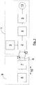
- a signal transmission device such as is preferably arranged on a punching device according to the invention, and the method for transmitting a sensor signal are in Fig. 1 shown schematically.
- the signal transmission device has a fixed transmitter unit 1, which has a coil 2, a pulse generator 3, an amplifier 4 and a demodulator 5.
- the coil 2 is inductively coupled to a coil 6, which is part of a tunable electrical resonant circuit 7.
- the resonant circuit 7 is also connected to a piezoelectric sensor 8, which changes or detunes the natural frequency of the resonant circuit 7 as a function of the voltage generated there.
- the resonant circuit 7 and the sensor 8 are arranged together in a carrier 9, which is movably mounted in the direction of arrow 10 and executes essentially an oscillating movement during operation.
- the carrier may be arranged on a movable machine part, in particular on a hold-down device.
- the natural frequency in the resonant circuit 7 is indirectly excited by the pulse generator 3, which generates a current in the coil 2 for this purpose at suitable time intervals.
- the resulting magnetic field induced in the coil 6 a current (arrow 11), whereby the resonant circuit 7 is excited.
- the oscillation or frequency in the oscillating circuit 7 is changed.
- the high frequency of the resonant circuit 7 is transmitted from the coil 6 to the coil 2 (arrow 12).
- the signal is then amplified by an amplifier 4 and forwarded to the demodulator 5.
- demodulation frequency or amplitude demodulation
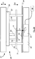
- Fig. 2a shows a detailed view of a known prior art embodiment of a punching device 21 having a bottom plate 22 on which a flat part or workpiece 24 is located.
- the upper tool 26 is movably mounted in the direction of arrow 27.
- the upper tool 26 has a top plate 28 to which the punch 29 is attached.
- the top plate 28 is connected via elastic elements 30, 30 'to a hold-down 31, to which a piezoelectric sensor 8 is fixed, which is connected via a cable connection 35 with the evaluation unit 34.
- For punching the upper tool 26 is lowered in the direction of arrow 32 until the hold-31 contacts the tool piece 24 and holds for the subsequent punching operation.
- the elastic elements 30, 30 ' are compressed, so that the pressure of the blank holder 31 increases on the workpiece 24.
- the punches 29, 29 ' cut the workpiece 24 into the desired shape, for which purpose the hold-down 31 has correspondingly formed openings for the punch 29.
- the upper tool 26 is raised again (counter to the direction of the arrow 32) so that the workpiece 24 can be forwarded. This process is repeated at periodic intervals and at corresponding production speeds within fractions of a second.
- the piezoelectric sensor 8 will generate a signal that deviates from the typical course such that the evaluation unit 34 interrupts the punching process so that the punching ram 33 or the foreign body can be removed. Due to the high process speeds during punching act on the upper tool 26 and thus also on the hold 31 and the cable connection 35 high acceleration forces that lead to the demolition of the cable connection 35 over time.
- FIG. 12 therefore shows a detailed view of a concrete embodiment of the present invention, with which the tearing off of the cable connection 35 is avoided.
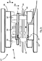
- This punching device 21 ' is substantially analogous to the punching device 21 according to the prior art ( Fig. 2a ), wherein on the bottom plate 22, a transmitter unit 23 is arranged with a coil 2. Further, a coil 6 is attached to the hold-down 31 in addition to a piezoelectric sensor 8, the part of the (in Fig. 2a not shown) resonant circuit 7 is. This makes it possible to dispense with a cable connection 35 between the movable part of the sensor device and the evaluation unit 34, whereby a tearing off of the cable connection is avoided. Incidentally, the transmission of the sensor signal 13 takes place in the manner already described with regard to Fig.
- Fig. 2c and d show the punch 21 'after Fig. 2b in a perspective view.
- a ferrite core 36 is shown, which amplifies the signal transmission between the coils 2 and 6 as ferromagnetic coupling. Incidentally, the operation is also identical.
- FIG. 3 a concrete embodiment of a punching device 21 'with two processing stations 41, 42, where appropriate, different punching operations are performed.
- the upper tool 26 is thereby moved by lifting cylinders 43, 43 'in the direction of arrow 27.
- the lifting cylinders 43, 43 ' are suspended on a solid frame 44. Laterally of the frame 44 corresponding to trained recesses 45, 45 'are arranged for the passage of the workpiece.
Description
Die vorliegende Erfindung betrifft eine Stanzvorrichtung gemäß dem Oberbegriff des Anspruchs 1 mit mindestens einem oszillierenden Maschinenteil, das mindestens einen piezoelektrischen Sensor besitzt.The present invention relates to a punching device according to the preamble of claim 1 with at least one oscillating machine part having at least one piezoelectric sensor.
Ferner betrifft die Erfindung ein Verfahren gemäß Anspruch 9 zur Übertragung eines Sensorsignals eines piezoelektrischen Sensors, der an einem oszillierenden Maschinenteil einer Stanzvorrichtung, insbesondere an einem Niederhalter, angeordnet ist.Furthermore, the invention relates to a method according to
Beim Stanzen werden Flachteile (bzw. Werkstücke oder Stanzprodukte) aus unterschiedlichen Werkstoffen, wie beispielsweise Blech, Pappe oder Textilien, mit einer Presse oder einem Schneidwerkzeug gefertigt. Dabei besteht eine Stanzvorrichtung üblicherweise aus einem Stempel und einer Matrize, die in einer Bodenplatte angeordnet sein kann.When punching flat parts (or workpieces or stamping products) made of different materials, such as sheet metal, cardboard or textiles, made with a press or a cutting tool. In this case, a punching device usually consists of a punch and a die, which can be arranged in a bottom plate.
Damit sichergestellt ist, dass das Flachteil (bzw. das Material zur Herstellung des Flachteils) beim Stanzen an der richtigen Stelle angeordnet ist und auch dort während des Stanzens verbleibt, werden die Flachteile mittels eines Niederlhalters auf die Bodenplatte gedrückt und dort fixiert. Nach dem Stanzen wird der Niederhalter angehoben, so dass das Flachteil einer weiteren Bearbeitungsstation übergeben werden kann. Die beim Stanzen entstehenden Abfälle, sogenannte Stanzbutzen, werden optimalerweise so abgeführt, dass sie die weiteren Stanzprozesse nicht behindern. Allerdings können Stanzbutzen während des Stanzprozesses auch ungewollt vom Stempel aus dem Butzenkanal hochgezogen werden und dann an zufälligen Stellen zwischen dem Flachteil und dem Niederhalter oder dem Stempel zum Liegen kommen. Beim anschließenden niederdrücken durch den Niederhalter oder beim anschließenden Stanzprozess beschädigen solche Stanzbutzen regelmäßig die Oberfläche der Flachteile, indem die Stanzbutzen Butzenabdrücke auf der Oberfläche hinterlassen.To ensure that the flat part (or the material for the production of the flat part) is arranged at the right place during punching and also remains there during the punching, the flat parts are pressed by means of a Niederlhalters on the bottom plate and fixed there. After punching the hold-down is raised, so that the flat part can be handed over to another processing station. The waste resulting from punching, so-called stamped slugs, are optimally removed in such a way that they do not obstruct the further punching processes. However, during the stamping process, punched slugs can also be unintentionally pulled up by the punch from the slug channel and then come to rest at random points between the flat part and the hold-down or the punch. During the subsequent depression by the hold-down device or during the subsequent punching process, such punches regularly damage the surface of the flat parts, as the stamped pieces leave the bump marks on the surface.
Zur Erkennung von Stanzbutzen wurden Stanzvorrichtungen der eingangs genannten Art geschaffen, bei denen das bewegliche Maschinenteil, insbesondere der Niederhalter, einen piezoelektrischen Sensor besitzt, der bei auftretenden Druckbelastungen oder einer Verformung ein elektrisches Signal erzeugt. Dieses Signal wird über ein elektrisches Kabel einer Auswerteeinheit zugeführt, wo die Daten ausgewertet werden. Sobald die Auswerteeinheit ein Signal erkennt, das auf eine zwischen dem beweglichen Maschinenteil und dem Flachteil angeordnete Stanzbutze hindeutet, wird der Stanzprozess sofort unterbrochen, so dass die Stanzbutzen entfernt werden können. Auf diese Weise wird vermieden, dass eine große Anzahl von Flachteilen mit unerwünschten Butzenabdrücken produziert wird, die teilweise nicht mehr an die Kunden ausgeliefert werden können.Punching devices of the type mentioned above have been provided for the recognition of punched slugs, in which the movable machine part, in particular the hold-down, has a piezoelectric sensor which generates an electrical signal when pressure loads or deformation occur. This signal is fed via an electrical cable to an evaluation unit, where the data are evaluated. As soon as the evaluation unit detects a signal which points to a punching rod arranged between the movable machine part and the flat part, the punching process is interrupted immediately, so that the punched slugs can be removed. In this way, it is avoided that a large number of flat parts is produced with undesirable Butzenabdrücken, some of which can no longer be delivered to customers.
Bei herkömmlichen Stanzmaschinen sind die piezoelektrischen Sensoren nachteiligerweise zur Datenübertragung über Kabel mit der Auswerteeinheit verbunden, was insbesondere bei Stanzmaschinen zu Problemen führt, bei denen das bewegliche Maschinenteil mit einer hohen Frequenz betrieben wird, womit die Sensoren und insbesondere die Kabelverbindungen einer hohen Beschleunigung ausgesetzt sind. Bereits bei Stanzmaschinen, die einen durchschnittlichen Durchlauf bzw. eine durchschnittliche Produktionsgeschwindigkeit besitzen, sind Beschleunigungskräfte von 1.000 G keine Seltenheit. Aufgrund der hohen Dauerbelastung reißt die Kabelverbindung an Sensoren bei solchen Stanzvorrichtungen regelmäßig ab, was mit langen und damit kostenaufwendigen Reparatur- und Wartungsarbeiten verbunden ist.In conventional punching machines, the piezoelectric sensors are disadvantageously connected to the evaluation unit for data transmission via cables, which leads in particular to punching machines to problems in which the movable machine part is operated at a high frequency, whereby the sensors and in particular the cable connections are exposed to high acceleration. Already in punching machines that have an average throughput or an average production speed, acceleration forces of 1,000 G are not uncommon. Due to the high continuous load, the cable connection tears off regularly on sensors in such punching devices, which is associated with long and thus costly repair and maintenance.
Weiterer Stand der Technik ist den Offenlegungsschriften
Es ist daher die Aufgabe der vorliegenden Erfindung, diese Nachteile zu beheben und die Gefahr eines Kabelabrisses an einem piezoelektrischen Sensor eines oszillierenden Maschinenteils auszuräumen.It is therefore the object of the present invention to overcome these disadvantages and to eliminate the risk of a cable break on a piezoelectric sensor of an oscillating machine part.
Diese Aufgabe wird durch die Stanzvorrichtung nach Anspruch 1 gelöst. Auf diese Weise können die Sensordaten durch eine induktive Kopplung von dem (beweglich gelagerten) Sensor an eine (ruhende) Empfängerspule (zweite Spule) übertragen werden. Von dort aus wird das Signal über eine Kabelverbindung an die Auswerteeinheit übertragen, wo das Sensorsignal ausgewertet wird. Insgesamt wird durch die kabellose Übertragung des Sensorsignals von der ersten Spule auf die zweite Spule ein Kabelabriss am Sensor und damit ein wartungsbedingter Stillstand der Stanzvorrichtung vermieden. Darüber hinaus dient die erfindungsgemäße Vorrichtung auch als Stempelbrucherkennung.This object is achieved by the punching device according to claim 1. In this way, the sensor data by an inductive coupling of the (movably mounted) sensor to a (stationary) receiver coil (second coil) are transmitted. From there, the signal is transmitted via a cable connection to the evaluation unit, where the sensor signal is evaluated. Overall, a cable break on the sensor and thus a maintenance-related stoppage of the punching device is avoided by the wireless transmission of the sensor signal from the first coil to the second coil. In addition, the device according to the invention also serves as a stamp breakage detection.
Bevorzugte Ausführungsformen der erfindungsgemäßen Stanzvorrichtung werden im Folgenden und in den Unteransprüchen beschrieben.Preferred embodiments of the punching device according to the invention are described below and in the subclaims.
Das von dem piezoelektrischen Sensor erzeugte Signal ist je nach der auftretenden Spannung relativ gering. Um insbesondere auch bei kleinen Signalstärken eine ausreichende Signalübertragung zu ermöglichen, bildet nach einer ersten bevorzugten Ausgestaltung die erste Spule zusammen mit dem piezoelektrischen Sensor und mindestens einer Kapazität - wie beispielsweise einem Kondensator - einen elektrischen Schwingkreis. In Abhängigkeit von der Induktivität der Spule und der Größe der Kapazität weist der Schwingkreis eine bestimmte Eigenfrequenz auf. Sobald der piezoelektrische Sensor verformt wird und hierdurch eine Spannung erzeugt wird, wird die Eigenfrequenz des Schwingkreises geändert bzw. verstimmt. Somit stellt die Änderung der Eigenfrequenz des Schwingkreises ein Maß für die Spannung und damit die Kraft dar, die auf den piezoelektrischen Sensor wirkt.The signal generated by the piezoelectric sensor is relatively small depending on the voltage occurring. In order to enable a sufficient signal transmission, particularly in the case of small signal strengths, according to a first preferred embodiment, the first coil together with the piezoelectric sensor and at least one capacitance-such as a capacitor-forms an electrical resonant circuit. Depending on the inductance of the coil and the size of the capacitance, the resonant circuit has a specific natural frequency. As soon as the piezoelectric sensor is deformed and thus a voltage is generated, the natural frequency of the resonant circuit is changed or detuned. Thus, the change in the natural frequency of the resonant circuit is a measure of the voltage and thus the force acting on the piezoelectric sensor.
Zum Anregen der Eigenfrequenz des Schwingkreises ist die zweite Spule vorzugsweise mit einer Sendereinheit bzw. einem Impulsgeber für die Übertragung elektrischer Energie auf die erste Spule verbunden. Durch die regelmäßige Abgabe von Impulsen in geeigneten Zeitabständen wird die Schwingung im Schwingkreis aufrechterhalten. Dabei wird durch die induktive Kopplung in der zweiten Spule ein Strom mit einer entsprechenden Stromstärke und Frequenz induziert. Dieses (modulierte) Signal wird an einen geeigneten Demodulator (Frequenz- oder Amplitudendemodulator) gesendet, so dass nach erfolgter Demodulation das ursprüngliche Sensorsignal der Auswerteeinheit übermittelt werden kann.To excite the natural frequency of the resonant circuit, the second coil is preferably connected to a transmitter unit or a pulse generator for the transmission of electrical energy to the first coil. By the regular emission of pulses at appropriate intervals, the oscillation is maintained in the resonant circuit. In this case, a current with a corresponding current intensity and frequency is induced by the inductive coupling in the second coil. This (modulated) signal is sent to a suitable demodulator (frequency or amplitude demodulator), so that after demodulation the original sensor signal can be transmitted to the evaluation unit.
Zur Verbesserung der induktiven Kopplung sind die erste und die zweite Spule vorzugsweise über ein ferromagnetisches Material, insbesondere einen Ferritkern, induktiv miteinander gekoppelt. Bei dieser Ausgestaltung sind die Spulen in längsaxialer Richtung voneinander beabstandet. Alternativ hierzu können die Spulen auch koaxial zueinander angeordnet sein, wobei die erste Spule die zweite Spule umgreift oder umgekehrt.To improve the inductive coupling, the first and the second coil are preferably inductively coupled together via a ferromagnetic material, in particular a ferrite core. In this embodiment, the coils are spaced apart in the longitudinal axial direction. Alternatively, the coils may also be arranged coaxially with each other, wherein the first coil surrounds the second coil or vice versa.
Nach einer weiteren bevorzugten Ausführungsform der Erfindung ist die erste Spule innerhalb eines Trägers angeordnet, der vorzugsweise ein- oder zweistückig mit dem oszillierenden Maschinenteil verbunden ist. Eine zweistückige Verbindung kann beispielsweise als eine Schraub- oder Steckverbindung zwischen dem Träger und dem oszillierenden Maschinenteil ausgeführt sein. Alternativ ist auch eine Integrierung des Trägers in dem oszillierenden Maschinenteil denkbar, womit eine einstückige Verbindung vorliegt. Hierzu kann der Träger beispielsweise mit dem oszillierenden Maschinenteil vergossen sein.According to a further preferred embodiment of the invention, the first coil is arranged within a carrier, which is preferably connected in one or two pieces with the oscillating machine part. A two-piece connection can be designed, for example, as a screw or plug connection between the carrier and the oscillating machine part. Alternatively, an integration of the carrier in the oscillating machine part is conceivable, so that there is a one-piece connection. For this purpose, the carrier may be cast, for example, with the oscillating machine part.
Nach einer weiteren bevorzugten Ausführungsform der erfindungsgemäßen Stanzvorrichtung ist das oszillierende Maschinenteil ein Niederhalter, wo sich der Einsatz einer kabellosen Sensordatenübertragung besonders bewährt hat.According to a further preferred embodiment of the punching device according to the invention, the oscillating machine part is a hold-down device, where the use of a wireless sensor data transmission has proven particularly useful.
Ein solcher Niederhalter ist vorzugsweise über elastische Elemente mit einer Oberplatte der Stanzvorrichtung verbunden, wobei an der Oberplatte der Stempel angeordnet ist. Zum Stanzen sind die Oberplatte, der Stempel und der Niederhalter längsaxial beweglich gelagert. Genaueres zu dem Arbeitsablauf beim Stanzen wird in der Figurenbeschreibung erläutert.Such a hold-down is preferably connected via elastic elements with a top plate of the punching device, wherein on the top plate of the stamp is arranged. For punching the top plate, the punch and the hold-down are mounted longitudinally axially movable. More details about the workflow during punching is explained in the description of the figures.
Die vorliegende Erfindung betrifft darüber hinaus ein Verfahren gemäß Anspruch 9 zur Übertragung eines Sensorsignals eines piezoelektrischen Sensors, der an einem oszilliereden Maschinenteil einer Stanzvorrichtung, insbesondere an einem Niederhalter, angeordnet ist. Erfindungsgemäß ist der piezoelektrische Sensor mit einer ersten Spule verbunden, die induktiv mit einer zweiten Spule gekoppelt ist, so dass ein an dem piezoelektrischen Sensor entstehendes Sensorsignal auf die zweite Spule übertragen und anschließend an eine Auswerteeinheit übermittelt wird. Durch dieses Verfahren ist ein kabelloses Übertragung des Sensorsignals möglich, so dass auf eine kabelgebundene Verbindung zwischen einer Auswerteeinheit und dem Sensor verzichtet werden kann. Ein Abreißen der Kabelverbindung aufgrund der beim Stanzen auftretenden Beschleunigungskräfte wird hierdurch vermieden.The present invention further relates to a method according to
Bevorzugte Ausführungsformen des erfindungsgemäßen Verfahrens werden im Folgenden und in den Unteransprüchen beschrieben.Preferred embodiments of the method according to the invention are described below and in the subclaims.
Es wurde bereits erläutert, dass das von dem piezoelektrischen Sensor erzeugte Signal je nach der auftretenden Spannung relativ gering ist. Um insbesondere auch bei kleinen Signalstärken eine ausreichende Auswertung des Signals zu ermöglichen, ist nach einer bevorzugten Ausgestaltung des erfindungsgemäßen Verfahrens vorgesehen, dass der piezoelektrische Sensor zusammen mit der ersten Spule und mindestens einer Kapazität einen ersten elektrischen Schwingkreis bildet, der durch eine Energieübertragung von der zweiten Spule auf die erste Spule angeregt wird, wobei sich die Schwingung der ersten Spule anschließend auf die zweite Spule überträgt. Die Energieübertragung von der zweiten Spule auf die erste Spule wird vorzugsweise über einen Impulsgeber durchgeführt, wodurch der Schwingkreis angeregt wird, der anschließend mit seiner Eigenfrequenz schwingt, die durch die Induktivität der Spule und die Größe der Kapazität gegeben ist. Ein durch den piezoelektrischen Sensor erzeugtes Sensorsignal ändert die im Schwingkreis angeregte Hochfrequenz, die auf die zweite Spule übertragen wird. Das Sensorsignal ergibt sich anschließend aus einer Demodulation (Frequenz- oder Amplitudendemodulation) des Hochfrequenzsignals an der zweiten Spule. Das so bestimmte Sensorsignal wird anschließend der Auswerteeinheit übermittelt und dort ausgewertet.It has already been explained that the signal generated by the piezoelectric sensor is relatively small, depending on the voltage that occurs. In order to allow a sufficient evaluation of the signal, especially in the case of small signal strengths, it is provided according to a preferred embodiment of the method according to the invention that the piezoelectric sensor together with the first coil and at least one capacitance forms a first electrical oscillating circuit, which by an energy transfer from the second Coil is excited to the first coil, wherein the oscillation of the first coil then transmits to the second coil. The energy transfer from the second coil to the first coil is preferably carried out via a pulse generator, whereby the resonant circuit is excited, which then oscillates at its natural frequency, which is given by the inductance of the coil and the size of the capacitance. A sensor signal generated by the piezoelectric sensor changes the high frequency excited in the oscillation circuit, which is transmitted to the second coil. The sensor signal then results from a demodulation (frequency or amplitude demodulation) of the high-frequency signal at the second coil. The thus determined sensor signal is then transmitted to the evaluation unit and evaluated there.
Konkrete Ausführungsformen der vorliegenden Erfindung werden im Folgenden anhand der Figuren erläutert. Es zeigen:
- Fig. 1:
- eine schematische Darstellung einer Übertragungsvorrichtung,
- Fig. 2a:
- eine Detailansicht einer Stanzvorrichtung nach dem Stand der Technik,
- Fig. 2b-c:
- Detailansichten einer Stanzvorrichtung und
- Fig. 3:
- eine Stanzvorrichtung.
- Fig. 1:
- a schematic representation of a transmission device,
- Fig. 2a:
- a detailed view of a punching device according to the prior art,
- Fig. 2b-c:
- Detail views of a punching device and
- 3:
- a punching device.
Eine Signalübertragungsvorrichtung, wie Sie vorzugsweise an einer erfindungsgemäßen Stanzvorrichtung angeordnet ist, und das Verfahren zur Übertragung eines Sensorsignals werden in
Sobald in dem piezoelektrischen Sensor 8 eine Spannung erzeugt wird, wird die Schwingung bzw. Frequenz in dem Schwingkreis 7 geändert. Durch die induktive Kopplung der Spulen 2 und 6 wird die Hochfrequenz des Schwingkreises 7 von der Spule 6 auf die Spule 2 übertragen (Pfeil 12). Das Signal wird anschließend durch einen Verstärker 4 verstärkt und zu dem Demodulator 5 weitergeleitet. Nach erfolgter Demodulation (Frequenz- oder Amplitudendemodulation) ergibt sich das ursprüngliche Sensorsignal 13, das Aufschluss über die mechanische Belastung und mithin über die Prozessänderung am piezoelektrischen Sensor 8 liefert und anhand dessen eine Auswerteeinheit (in
Diese Stanzvorrichtung 21' ist im wesentlichen analog zu der Stanzvorrichtung 21 nach dem Stand der Technik (
Schließlich zeigt
Claims (12)
- Stamping device with at least one oscillating machine part, which has at least one piezoelectric sensor (8),
characterized in that
the piezoelectric sensor (8) is electrically connected to at least one first coil (6) attached to the oscillating machine part and inductively coupled to at least one second stationary coil (2). - Stamping device according to claim 1, characterized in that the first coil (6) builds an electrical oscillating circuit (7) together with the piezoelectric sensor (8) and at least one capacitor.
- Stamping device according to one of claims 1 or 2, characterized in that the first coil (6) is arranged within a carrier (9), which is preferably connected in one or two pieces with the oscillating machine part.
- Stamping device according to one of claims 1 to 3, characterized in that the first coil (6) and the second coil (2) are inductively coupled together via a ferromagnetic material, in particular a ferrite core (36).
- Stamping device according to one of claims 1 to 4, characterized in that the second coil (2) is connected with a transmitter unit (23) for the transmission of electrical energy to the first coil (6).
- Stamping device according to one of claims 1 to 5, characterized in that the oscillating machine part is a hold-down device (31).
- Stamping device according to one of claims 1 to 6, characterized in that the hold-down device (31) is connected with a top plate (28) of the stamping device (21') via elastic elements (30, 30'), wherein at least one stamp (29) is arranged on the top plate (28).
- Stamping device according to one of claims 1 to 7, characterized in that the upper plate (28), the stamp (29) and the hold-down device (31) are mounted longitudinally axially movable for stamping.
- A method for transmitting a sensor signal (13) of a piezoelectric sensor (8) which is arranged on an oscillating machine part of a stamping device (21'), in particular on a hold-down device (31), wherein the piezoelectric sensor (8) is connected with a first coil (2), attached to the oscillating machine part, which is inductively coupled to a second stationary coil (2), so that a resulting sensor signal (13) at the piezoelectric sensor (8) is transmitted to the second coil (2) and then transmitted to an evaluation unit (34).
- The method according to claim 9, characterized in that the piezoelectric sensor (8) builds a first electrical oscillating circuit (7) together with the first coil (6) and at least one capacitor, the electrical oscillating circuit (7) is activated by an energy transfer from the second coil (2) to the first coil (6), wherein the oscillation of the first coil (6) subsequently transmits itself to the second coil (2).
- The method according to claim 10, characterized in that the sensor signal (13) changes an activated high frequency in the oscillating circuit (7).
- The method according to any one of claims 9 to 11, characterized in that the sensor signal (13) results from a demodulation of the high-frequency signal at the second coil.
Applications Claiming Priority (2)
| Application Number | Priority Date | Filing Date | Title |
|---|---|---|---|
| DE102012023665.4A DE102012023665A1 (en) | 2012-12-04 | 2012-12-04 | Punching device with a sensor and method for transmitting a sensor signal |
| PCT/DE2013/000710 WO2014086328A1 (en) | 2012-12-04 | 2013-11-29 | Stamping device with a sensor and method for transmitting a sensor signal |
Publications (2)
| Publication Number | Publication Date |
|---|---|
| EP2928682A1 EP2928682A1 (en) | 2015-10-14 |
| EP2928682B1 true EP2928682B1 (en) | 2018-05-30 |
Family
ID=50030017
Family Applications (1)
| Application Number | Title | Priority Date | Filing Date |
|---|---|---|---|
| EP13826553.3A Not-in-force EP2928682B1 (en) | 2012-12-04 | 2013-11-29 | Stamping device with a sensor and method for transmitting a sensor signal |
Country Status (3)
| Country | Link |
|---|---|
| EP (1) | EP2928682B1 (en) |
| DE (1) | DE102012023665A1 (en) |
| WO (1) | WO2014086328A1 (en) |
Families Citing this family (2)
| Publication number | Priority date | Publication date | Assignee | Title |
|---|---|---|---|---|
| DE102015211622A1 (en) | 2015-06-23 | 2016-12-29 | Multivac Sepp Haggenmüller Se & Co. Kg | Thermoforming packaging machine with foil punch |
| US11592499B2 (en) | 2019-12-10 | 2023-02-28 | Barnes Group Inc. | Wireless sensor with beacon technology |
Citations (1)
| Publication number | Priority date | Publication date | Assignee | Title |
|---|---|---|---|---|
| EP1057586A2 (en) * | 1999-06-02 | 2000-12-06 | Fraunhofer-Gesellschaft zur Förderung der angewandten Forschung e.V. | Tool for forming, punching or injection moulding |
Family Cites Families (7)
| Publication number | Priority date | Publication date | Assignee | Title |
|---|---|---|---|---|
| US3444390A (en) * | 1968-01-12 | 1969-05-13 | Hyde Park Electronics Inc | Press impact sensor |
| AU621146B2 (en) * | 1988-09-08 | 1992-03-05 | Trw Steering & Industrial Products (Japan) Co., Ltd. | Apparatus and method of detecting abnormal load of pressurizing apparatus |
| DE10055113A1 (en) * | 2000-11-07 | 2002-05-08 | Daimler Chrysler Ag | Cutting tool comprises cutting punch guide using piezoelectric actuators formed by quartz stack |
| DE10142273A1 (en) * | 2001-08-29 | 2003-03-20 | Dittel Walter Gmbh | measuring data |
| DE10163734B4 (en) * | 2001-12-21 | 2005-06-16 | Growth Finance Ag | Method and device for monitoring tools |
| DE102010001144A1 (en) * | 2010-01-22 | 2011-07-28 | Fraunhofer-Gesellschaft zur Förderung der angewandten Forschung e.V., 80686 | Mechanical connection component e.g. screw, for monitoring e.g. screw connections in bridge, has wireless interface for wireless detection of information describing mechanical load of component based on electrical property of sensor layer |
| DE102011011824A1 (en) * | 2011-02-19 | 2012-08-23 | Volkswagen Ag | Stroke rate sensor for monitoring tool of machine tool, particularly press or cutting tool, for pressing or cutting of sheet metal components, has converter unit that is arranged at tool |
-
2012
- 2012-12-04 DE DE102012023665.4A patent/DE102012023665A1/en not_active Withdrawn
-
2013
- 2013-11-29 WO PCT/DE2013/000710 patent/WO2014086328A1/en active Application Filing
- 2013-11-29 EP EP13826553.3A patent/EP2928682B1/en not_active Not-in-force
Patent Citations (1)
| Publication number | Priority date | Publication date | Assignee | Title |
|---|---|---|---|---|
| EP1057586A2 (en) * | 1999-06-02 | 2000-12-06 | Fraunhofer-Gesellschaft zur Förderung der angewandten Forschung e.V. | Tool for forming, punching or injection moulding |
Also Published As
| Publication number | Publication date |
|---|---|
| WO2014086328A1 (en) | 2014-06-12 |
| EP2928682A1 (en) | 2015-10-14 |
| DE102012023665A1 (en) | 2014-06-05 |
Similar Documents
| Publication | Publication Date | Title |
|---|---|---|
| DE3739029C2 (en) | Stamping or nibbling process and device therefor | |
| EP3233323B1 (en) | Bending tool having a longitudinal-offset measuring device | |
| EP2701861B1 (en) | Method and device for producing flangeless drawn parts | |
| EP2452790A1 (en) | Processing station for a stamping machine and method for removing a test blank | |
| WO2003015951A1 (en) | Production device, in particular a folding press and a method for operating a production device | |
| EP2669024A1 (en) | Machine tool and method for pushing out a workpiece part | |
| EP2928682B1 (en) | Stamping device with a sensor and method for transmitting a sensor signal | |
| EP3727830B1 (en) | Device and method for monitoring a wedge drive tool | |
| DE102018102809B4 (en) | Press and procedures for its operation | |
| CH678159A5 (en) | ||
| WO2008119090A1 (en) | Method for establishing a setup parameter value for a bending press | |
| EP0642853A1 (en) | Method of joining thin plates and device for carrying out the method | |
| EP1764194B1 (en) | Punch and method for using such a punch | |
| EP3088315B2 (en) | Deep draw packaging machine with strip puncher | |
| DE202012011658U1 (en) | Punching device with a sensor | |
| DE102006053223B3 (en) | Sheet metal punch has centering tip surrounded by circular shoulder in close proximity to surplus metal ejector pins | |
| EP1207974B1 (en) | Deep-drawing method and deep-drawing die | |
| DE102010000094B4 (en) | Tool and method for producing can bodies | |
| DE2724886C3 (en) | Method and device for producing shell-like workpieces | |
| DE102011053084A1 (en) | Apparatus and method for producing can bodies with cutting device | |
| EP2384833B1 (en) | Blank holder control in the production of can bodies | |
| EP0648618B1 (en) | Coin press for stamping or perforating | |
| DE10063154B4 (en) | Forging press with adjusting device on the die side | |
| DE102011056462B4 (en) | Method for producing a container body | |
| WO2016074668A2 (en) | Tool for producing cups, and blanking and drawing press |
Legal Events
| Date | Code | Title | Description |
|---|---|---|---|
| PUAI | Public reference made under article 153(3) epc to a published international application that has entered the european phase |
Free format text: ORIGINAL CODE: 0009012 |
|
| 17P | Request for examination filed |
Effective date: 20150519 |
|
| AK | Designated contracting states |
Kind code of ref document: A1 Designated state(s): AL AT BE BG CH CY CZ DE DK EE ES FI FR GB GR HR HU IE IS IT LI LT LU LV MC MK MT NL NO PL PT RO RS SE SI SK SM TR |
|
| AX | Request for extension of the european patent |
Extension state: BA ME |
|
| DAX | Request for extension of the european patent (deleted) | ||
| RAP1 | Party data changed (applicant data changed or rights of an application transferred) |
Owner name: MARPOSS MONITORING SOLUTIONS GMBH |
|
| GRAP | Despatch of communication of intention to grant a patent |
Free format text: ORIGINAL CODE: EPIDOSNIGR1 |
|
| INTG | Intention to grant announced |
Effective date: 20180205 |
|
| GRAJ | Information related to disapproval of communication of intention to grant by the applicant or resumption of examination proceedings by the epo deleted |
Free format text: ORIGINAL CODE: EPIDOSDIGR1 |
|
| GRAP | Despatch of communication of intention to grant a patent |
Free format text: ORIGINAL CODE: EPIDOSNIGR1 |
|
| INTC | Intention to grant announced (deleted) | ||
| GRAS | Grant fee paid |
Free format text: ORIGINAL CODE: EPIDOSNIGR3 |
|
| INTG | Intention to grant announced |
Effective date: 20180328 |
|
| GRAA | (expected) grant |
Free format text: ORIGINAL CODE: 0009210 |
|
| AK | Designated contracting states |
Kind code of ref document: B1 Designated state(s): AL AT BE BG CH CY CZ DE DK EE ES FI FR GB GR HR HU IE IS IT LI LT LU LV MC MK MT NL NO PL PT RO RS SE SI SK SM TR |
|
| REG | Reference to a national code |
Ref country code: GB Ref legal event code: FG4D Free format text: NOT ENGLISH |
|
| REG | Reference to a national code |
Ref country code: CH Ref legal event code: EP |
|
| REG | Reference to a national code |
Ref country code: AT Ref legal event code: REF Ref document number: 1003184 Country of ref document: AT Kind code of ref document: T Effective date: 20180615 |
|
| REG | Reference to a national code |
Ref country code: IE Ref legal event code: FG4D Free format text: LANGUAGE OF EP DOCUMENT: GERMAN |
|
| REG | Reference to a national code |
Ref country code: DE Ref legal event code: R096 Ref document number: 502013010296 Country of ref document: DE |
|
| REG | Reference to a national code |
Ref country code: NL Ref legal event code: MP Effective date: 20180530 |
|
| REG | Reference to a national code |
Ref country code: LT Ref legal event code: MG4D |
|
| PG25 | Lapsed in a contracting state [announced via postgrant information from national office to epo] |
Ref country code: BG Free format text: LAPSE BECAUSE OF FAILURE TO SUBMIT A TRANSLATION OF THE DESCRIPTION OR TO PAY THE FEE WITHIN THE PRESCRIBED TIME-LIMIT Effective date: 20180830 Ref country code: FI Free format text: LAPSE BECAUSE OF FAILURE TO SUBMIT A TRANSLATION OF THE DESCRIPTION OR TO PAY THE FEE WITHIN THE PRESCRIBED TIME-LIMIT Effective date: 20180530 Ref country code: NO Free format text: LAPSE BECAUSE OF FAILURE TO SUBMIT A TRANSLATION OF THE DESCRIPTION OR TO PAY THE FEE WITHIN THE PRESCRIBED TIME-LIMIT Effective date: 20180830 Ref country code: CY Free format text: LAPSE BECAUSE OF FAILURE TO SUBMIT A TRANSLATION OF THE DESCRIPTION OR TO PAY THE FEE WITHIN THE PRESCRIBED TIME-LIMIT Effective date: 20180530 Ref country code: SE Free format text: LAPSE BECAUSE OF FAILURE TO SUBMIT A TRANSLATION OF THE DESCRIPTION OR TO PAY THE FEE WITHIN THE PRESCRIBED TIME-LIMIT Effective date: 20180530 Ref country code: LT Free format text: LAPSE BECAUSE OF FAILURE TO SUBMIT A TRANSLATION OF THE DESCRIPTION OR TO PAY THE FEE WITHIN THE PRESCRIBED TIME-LIMIT Effective date: 20180530 Ref country code: ES Free format text: LAPSE BECAUSE OF FAILURE TO SUBMIT A TRANSLATION OF THE DESCRIPTION OR TO PAY THE FEE WITHIN THE PRESCRIBED TIME-LIMIT Effective date: 20180530 |
|
| PG25 | Lapsed in a contracting state [announced via postgrant information from national office to epo] |
Ref country code: LV Free format text: LAPSE BECAUSE OF FAILURE TO SUBMIT A TRANSLATION OF THE DESCRIPTION OR TO PAY THE FEE WITHIN THE PRESCRIBED TIME-LIMIT Effective date: 20180530 Ref country code: HR Free format text: LAPSE BECAUSE OF FAILURE TO SUBMIT A TRANSLATION OF THE DESCRIPTION OR TO PAY THE FEE WITHIN THE PRESCRIBED TIME-LIMIT Effective date: 20180530 Ref country code: GR Free format text: LAPSE BECAUSE OF FAILURE TO SUBMIT A TRANSLATION OF THE DESCRIPTION OR TO PAY THE FEE WITHIN THE PRESCRIBED TIME-LIMIT Effective date: 20180831 Ref country code: RS Free format text: LAPSE BECAUSE OF FAILURE TO SUBMIT A TRANSLATION OF THE DESCRIPTION OR TO PAY THE FEE WITHIN THE PRESCRIBED TIME-LIMIT Effective date: 20180530 |
|
| PG25 | Lapsed in a contracting state [announced via postgrant information from national office to epo] |
Ref country code: NL Free format text: LAPSE BECAUSE OF FAILURE TO SUBMIT A TRANSLATION OF THE DESCRIPTION OR TO PAY THE FEE WITHIN THE PRESCRIBED TIME-LIMIT Effective date: 20180530 |
|
| PG25 | Lapsed in a contracting state [announced via postgrant information from national office to epo] |
Ref country code: PL Free format text: LAPSE BECAUSE OF FAILURE TO SUBMIT A TRANSLATION OF THE DESCRIPTION OR TO PAY THE FEE WITHIN THE PRESCRIBED TIME-LIMIT Effective date: 20180530 Ref country code: EE Free format text: LAPSE BECAUSE OF FAILURE TO SUBMIT A TRANSLATION OF THE DESCRIPTION OR TO PAY THE FEE WITHIN THE PRESCRIBED TIME-LIMIT Effective date: 20180530 Ref country code: DK Free format text: LAPSE BECAUSE OF FAILURE TO SUBMIT A TRANSLATION OF THE DESCRIPTION OR TO PAY THE FEE WITHIN THE PRESCRIBED TIME-LIMIT Effective date: 20180530 Ref country code: CZ Free format text: LAPSE BECAUSE OF FAILURE TO SUBMIT A TRANSLATION OF THE DESCRIPTION OR TO PAY THE FEE WITHIN THE PRESCRIBED TIME-LIMIT Effective date: 20180530 Ref country code: RO Free format text: LAPSE BECAUSE OF FAILURE TO SUBMIT A TRANSLATION OF THE DESCRIPTION OR TO PAY THE FEE WITHIN THE PRESCRIBED TIME-LIMIT Effective date: 20180530 Ref country code: SK Free format text: LAPSE BECAUSE OF FAILURE TO SUBMIT A TRANSLATION OF THE DESCRIPTION OR TO PAY THE FEE WITHIN THE PRESCRIBED TIME-LIMIT Effective date: 20180530 |
|
| PG25 | Lapsed in a contracting state [announced via postgrant information from national office to epo] |
Ref country code: IT Free format text: LAPSE BECAUSE OF FAILURE TO SUBMIT A TRANSLATION OF THE DESCRIPTION OR TO PAY THE FEE WITHIN THE PRESCRIBED TIME-LIMIT Effective date: 20180530 Ref country code: SM Free format text: LAPSE BECAUSE OF FAILURE TO SUBMIT A TRANSLATION OF THE DESCRIPTION OR TO PAY THE FEE WITHIN THE PRESCRIBED TIME-LIMIT Effective date: 20180530 |
|
| REG | Reference to a national code |
Ref country code: DE Ref legal event code: R097 Ref document number: 502013010296 Country of ref document: DE |
|
| PLBE | No opposition filed within time limit |
Free format text: ORIGINAL CODE: 0009261 |
|
| STAA | Information on the status of an ep patent application or granted ep patent |
Free format text: STATUS: NO OPPOSITION FILED WITHIN TIME LIMIT |
|
| 26N | No opposition filed |
Effective date: 20190301 |
|
| PG25 | Lapsed in a contracting state [announced via postgrant information from national office to epo] |
Ref country code: SI Free format text: LAPSE BECAUSE OF FAILURE TO SUBMIT A TRANSLATION OF THE DESCRIPTION OR TO PAY THE FEE WITHIN THE PRESCRIBED TIME-LIMIT Effective date: 20180530 |
|
| REG | Reference to a national code |
Ref country code: DE Ref legal event code: R119 Ref document number: 502013010296 Country of ref document: DE |
|
| REG | Reference to a national code |
Ref country code: CH Ref legal event code: PL |
|
| GBPC | Gb: european patent ceased through non-payment of renewal fee |
Effective date: 20181129 |
|
| PG25 | Lapsed in a contracting state [announced via postgrant information from national office to epo] |
Ref country code: LU Free format text: LAPSE BECAUSE OF NON-PAYMENT OF DUE FEES Effective date: 20181129 Ref country code: MC Free format text: LAPSE BECAUSE OF FAILURE TO SUBMIT A TRANSLATION OF THE DESCRIPTION OR TO PAY THE FEE WITHIN THE PRESCRIBED TIME-LIMIT Effective date: 20180530 |
|
| REG | Reference to a national code |
Ref country code: BE Ref legal event code: MM Effective date: 20181130 |
|
| REG | Reference to a national code |
Ref country code: IE Ref legal event code: MM4A |
|
| PG25 | Lapsed in a contracting state [announced via postgrant information from national office to epo] |
Ref country code: CH Free format text: LAPSE BECAUSE OF NON-PAYMENT OF DUE FEES Effective date: 20181130 Ref country code: LI Free format text: LAPSE BECAUSE OF NON-PAYMENT OF DUE FEES Effective date: 20181130 |
|
| PG25 | Lapsed in a contracting state [announced via postgrant information from national office to epo] |
Ref country code: DE Free format text: LAPSE BECAUSE OF NON-PAYMENT OF DUE FEES Effective date: 20190601 Ref country code: IE Free format text: LAPSE BECAUSE OF NON-PAYMENT OF DUE FEES Effective date: 20181129 Ref country code: FR Free format text: LAPSE BECAUSE OF NON-PAYMENT OF DUE FEES Effective date: 20181130 |
|
| PG25 | Lapsed in a contracting state [announced via postgrant information from national office to epo] |
Ref country code: AL Free format text: LAPSE BECAUSE OF FAILURE TO SUBMIT A TRANSLATION OF THE DESCRIPTION OR TO PAY THE FEE WITHIN THE PRESCRIBED TIME-LIMIT Effective date: 20180530 Ref country code: BE Free format text: LAPSE BECAUSE OF NON-PAYMENT OF DUE FEES Effective date: 20181130 |
|
| PG25 | Lapsed in a contracting state [announced via postgrant information from national office to epo] |
Ref country code: GB Free format text: LAPSE BECAUSE OF NON-PAYMENT OF DUE FEES Effective date: 20181129 |
|
| REG | Reference to a national code |
Ref country code: AT Ref legal event code: MM01 Ref document number: 1003184 Country of ref document: AT Kind code of ref document: T Effective date: 20181129 |
|
| PG25 | Lapsed in a contracting state [announced via postgrant information from national office to epo] |
Ref country code: AT Free format text: LAPSE BECAUSE OF NON-PAYMENT OF DUE FEES Effective date: 20181129 Ref country code: MT Free format text: LAPSE BECAUSE OF FAILURE TO SUBMIT A TRANSLATION OF THE DESCRIPTION OR TO PAY THE FEE WITHIN THE PRESCRIBED TIME-LIMIT Effective date: 20180530 |
|
| PG25 | Lapsed in a contracting state [announced via postgrant information from national office to epo] |
Ref country code: TR Free format text: LAPSE BECAUSE OF FAILURE TO SUBMIT A TRANSLATION OF THE DESCRIPTION OR TO PAY THE FEE WITHIN THE PRESCRIBED TIME-LIMIT Effective date: 20180530 |
|
| PG25 | Lapsed in a contracting state [announced via postgrant information from national office to epo] |
Ref country code: PT Free format text: LAPSE BECAUSE OF FAILURE TO SUBMIT A TRANSLATION OF THE DESCRIPTION OR TO PAY THE FEE WITHIN THE PRESCRIBED TIME-LIMIT Effective date: 20180530 |
|
| PG25 | Lapsed in a contracting state [announced via postgrant information from national office to epo] |
Ref country code: MK Free format text: LAPSE BECAUSE OF NON-PAYMENT OF DUE FEES Effective date: 20180530 Ref country code: HU Free format text: LAPSE BECAUSE OF FAILURE TO SUBMIT A TRANSLATION OF THE DESCRIPTION OR TO PAY THE FEE WITHIN THE PRESCRIBED TIME-LIMIT; INVALID AB INITIO Effective date: 20131129 |
|
| PG25 | Lapsed in a contracting state [announced via postgrant information from national office to epo] |
Ref country code: IS Free format text: LAPSE BECAUSE OF FAILURE TO SUBMIT A TRANSLATION OF THE DESCRIPTION OR TO PAY THE FEE WITHIN THE PRESCRIBED TIME-LIMIT Effective date: 20180930 |