EP1057586A2 - Tool for forming, punching or injection moulding - Google Patents
Tool for forming, punching or injection moulding Download PDFInfo
- Publication number
- EP1057586A2 EP1057586A2 EP00111200A EP00111200A EP1057586A2 EP 1057586 A2 EP1057586 A2 EP 1057586A2 EP 00111200 A EP00111200 A EP 00111200A EP 00111200 A EP00111200 A EP 00111200A EP 1057586 A2 EP1057586 A2 EP 1057586A2
- Authority
- EP
- European Patent Office
- Prior art keywords
- tool
- layer
- tool according
- sensors
- module
- Prior art date
- Legal status (The legal status is an assumption and is not a legal conclusion. Google has not performed a legal analysis and makes no representation as to the accuracy of the status listed.)
- Granted
Links
Images


Classifications
-
- G—PHYSICS
- G01—MEASURING; TESTING
- G01L—MEASURING FORCE, STRESS, TORQUE, WORK, MECHANICAL POWER, MECHANICAL EFFICIENCY, OR FLUID PRESSURE
- G01L5/00—Apparatus for, or methods of, measuring force, work, mechanical power, or torque, specially adapted for specific purposes
- G01L5/0061—Force sensors associated with industrial machines or actuators
- G01L5/0076—Force sensors associated with manufacturing machines
-
- B—PERFORMING OPERATIONS; TRANSPORTING
- B21—MECHANICAL METAL-WORKING WITHOUT ESSENTIALLY REMOVING MATERIAL; PUNCHING METAL
- B21D—WORKING OR PROCESSING OF SHEET METAL OR METAL TUBES, RODS OR PROFILES WITHOUT ESSENTIALLY REMOVING MATERIAL; PUNCHING METAL
- B21D37/00—Tools as parts of machines covered by this subclass
-
- B—PERFORMING OPERATIONS; TRANSPORTING
- B30—PRESSES
- B30B—PRESSES IN GENERAL
- B30B15/00—Details of, or accessories for, presses; Auxiliary measures in connection with pressing
- B30B15/0094—Press load monitoring means
-
- B—PERFORMING OPERATIONS; TRANSPORTING
- B30—PRESSES
- B30B—PRESSES IN GENERAL
- B30B15/00—Details of, or accessories for, presses; Auxiliary measures in connection with pressing
- B30B15/06—Platens or press rams
-
- G—PHYSICS
- G01—MEASURING; TESTING
- G01L—MEASURING FORCE, STRESS, TORQUE, WORK, MECHANICAL POWER, MECHANICAL EFFICIENCY, OR FLUID PRESSURE
- G01L5/00—Apparatus for, or methods of, measuring force, work, mechanical power, or torque, specially adapted for specific purposes
- G01L5/0004—Force transducers adapted for mounting in a bore of the force receiving structure
Landscapes
- Engineering & Computer Science (AREA)
- Mechanical Engineering (AREA)
- Physics & Mathematics (AREA)
- General Physics & Mathematics (AREA)
- Chemical & Material Sciences (AREA)
- Analytical Chemistry (AREA)
- Cutting Tools, Boring Holders, And Turrets (AREA)
- Pens And Brushes (AREA)
- Adornments (AREA)
- Moulds For Moulding Plastics Or The Like (AREA)
Abstract
Description
Die vorliegende Erfindung bezieht sich auf ein Werkzeug für die Umform-, Stanz- oder Spritzgußtechnik.The present invention relates to a tool for forming, stamping or injection molding technology.
Im Bereich der spanlosen Verarbeitung werden zur Verminderung tribologischer Probleme vielfach verfahrensoptimierte Hilfsstoffe eingesetzt. Abgesehen von den damit verbundenen Kosten und Umweltbelastungen bietet der Einsatz verfahrensoptimierter Hilfsstoffe jedoch keinen vollständigen Schutz für die eingesetzten Werkzeuge, so daß es zu deren lokalem Verschleiß, beispielsweise durch Kaltverschweißung, Abrasion oder Oberflächenermüdung, kommen kann. In der spanlosen Verarbeitung setzt sich daher zunehmend durch, daß die Oberfläche der Werkzeuge mit einer dünnen, tribologisch optimierten Schicht zu versehen. Beispielsweise werden für unlegierte Tiefziehbleche erfolgreich TiN-Schichten eingesetzt, während bei Nichteisenmetallen mit CrN-Schichten überzeugende Verbesserungen erzielt wurden. Noch härtere Schichten aus TiCN werden mittlerweile erfolgreich bei der Umformung von hochlegierten Blechen eingesetzt. Neuere Entwicklungen weisen auf das hohe Eignungspotential von hochvernetzten Kohlenwasserstoff-Schichten hin, die sich derzeit jedoch noch in der Erprobungsphase befinden.In the field of non-cutting processing are used for reduction tribological problems are often process-optimized Auxiliaries used. Except the associated costs and environmental pollution however, the use of process-optimized auxiliaries no complete protection for the used Tools so that there is local wear, for example by cold welding, abrasion or Surface fatigue. In the chipless Processing is therefore increasingly becoming the norm the surface of the tools with a thin, tribological to provide an optimized layer. For example become successful for unalloyed deep-drawn sheets TiN layers are used, while non-ferrous metals convincing improvements with CrN layers were achieved. Even harder layers TiCN are now successfully used in the forming process of high-alloy sheets. Newer Developments point to the high suitability potential from highly cross-linked hydrocarbon layers, which is currently still in the testing phase are located.
Bei der Verformung wird die Oberfläche der Werkzeuge extrem unterschiedlichen mechanischen und thermischen Belastungen ausgesetzt. Die Kenntnis dieser lokal auf die Oberfläche einwirkenden Kräfte, beispielsweise Zug-, Druck- oder Scherkräfte im Bereich von Ziehradien oder komplexen Formteilen, Oberflächenzugkräfte im Bereich des Niederhalters, würde bei der Gestaltung von Werkzeugen als auch bei der Prozeßführung neue Möglichkeiten der Maschinensteuerung eröffnen.During the deformation, the surface of the tools extremely different mechanical and thermal Exposed to stress. Knowing this locally forces acting on the surface, for example Tensile, compressive or shear forces in the area of drawing radii or complex molded parts, surface tensile forces in the area of the hold-down device, would in the design of tools as well as in process control open up new possibilities for machine control.
Beispielsweise offenbart die EP 0 685 297 A1 ein Werkzeug für die Umform- und Zerspanungstechnik mit einer Sensorandordnung, wobei die Sensoren direkt auf der Verschleißfläche des Werkzeugs angeordnet sind. Die Sensoren bestehen dabei beispielsweise aus einer Isolationsschicht, sensorischen Metallschichten und Verschleißschutzschichten, wodurch ein mechanisch belastbarer geschlossener Schichtaufbau entsteht. Diese Schrift zeigt einen derartigen Aufbau lediglich für zerspanende Werkzeuge wie beispielsweise Wendeschneidplatten. Aus dieser Schrift ergibt sich jedoch keinerlei Hinweis für die Umform-, Stanz- oder Spritzgußwerkzeugen auftretenden Probleme. Denn letztere besitzen spezifische Formgebungen, so daß eine Kontaktierung und Auskopplung an der Funktionsoberfläche, wie in der EP 0 685 297 A1 beschrieben, nur sehr eingeschränkt in Frage kommen würde. For example, EP 0 685 297 A1 discloses a Tool for the forming and machining technology with a sensor arrangement, the sensors directly on the wear surface of the tool are arranged. The sensors consist of, for example Insulation layer, sensory metal layers and Wear protection layers, which makes a mechanically resilient closed layer structure is created. This Scripture shows such a structure only for cutting tools such as indexable inserts. However, from this script results no notice for the forming, stamping or Injection mold problems encountered. Because the latter have specific shapes, so that a Contacting and decoupling on the functional surface, as described in EP 0 685 297 A1, only would be very limited.
Die WO 87/04236 offenbart eine mechanische Komponente mit darauf in Dünnschichttechnik erzeugten elektrischen Schaltkreisen und Wandlern. Die DE 40 34 702.8 offenbart wiederum eine Vorrichtung zur Prüfung aktiver Werkzeuge von Gesenkbiegemaschinen und Biegestempel. Bei dieser Druckschrift wird die Höhe und die Schräge von Biegewerkzeugen mittels externer Sensoren erfaßt. Die Messung findet daher auch nicht während der Betriebsphase statt, sondern ohne Beanspruchung in der Ruhephase des Werkzeugs.WO 87/04236 discloses a mechanical component with electrical produced on it using thin-film technology Circuits and converters. DE 40 34 702.8 again discloses an active testing device Die bending machine tools and dies. In this publication, the height and the Inclination of bending tools using external sensors detected. The measurement therefore does not take place during during the operating phase, but without stress in the idle phase of the tool.
Aufgabe der vorliegenden Erfindung ist es daher, ein Werkzeug für die Umform-, Stanz- und Spritzgußtechnik zur Verfügung zu stellen, bei dem direkt und unmittelbar wichtige Verfahrensparameter wie beispielsweise Temperatur, Druck, Scherkraft und/oder Deformation lokal und kontinuierlich erfaßt werden können.The object of the present invention is therefore a Tool for forming, stamping and injection molding technology to provide directly and immediately important process parameters such as Temperature, pressure, shear and / or deformation can be recorded locally and continuously.
Weiterhin ist es Aufgabe der vorliegenden Erfindung ein Verfahren zur Herstellung derartiger Werkzeuge anzugeben.It is also an object of the present invention a method of manufacturing such tools specify.
Diese Aufgabe wird durch das Werkzeug nach Anspruch 1
sowie das Verfahren nach Anspruch 15 gelöst. Vorteilhafte
Weiterbildungen des erfindungsgemäßen Werkzeuges
und des erfindungsgemäßen Verfahrens werden in
den abhängigen Ansprüchen gegeben.This object is achieved by the tool according to
Das erfindungsgemäße Werkzeug weist ein Modul auf, auf dessen Oberfläche eine Anordnung mehrerer Dünnschichtsensoren vorgesehen ist. Die Oberfläche des Moduls bildet dabei gemeinsam mit der Funktionsoberfläche des Werkzeugs eine einzige durchgehende angepaßte Oberfläche, die an die Werkzeugkontur angepaßt ist. Durch diese Anordnung ist es möglich, lokal und an mehreren Stellen zugleich und auch kontinuierlich verschiedene Parameter wie beispielsweise Temperatur, Druck, Scherkraft und/oder Deformation des Werkzeugs zu bestimmen. Bei dem erfindungsgemäßen Werkzeug ist bei Einsatz des Verschleißsensors auch die Erfassung von Verschleiß des Werkzeugs selbst möglich. Dies ermöglicht beispielsweise den Verschleiß des Werkzeugs kontinuierlich aufzuzeichnen und so ohne weitere Stichprobennahme zum richtigen Zeitpunkt das Werkzeug auszutauschen. Die Werkzeuge für die Umform-, Stanz- oder Spritzgußtechnik besitzen sehr unterschiedliche Formen und Ausdehnungen. Sie reichen von einfachen Stempeln mit Zylindergeometrien und Abmessungen im Millimeterbereich bis zu tonnenschweren Formen mit Abmessungen im Quadratmeterbereich. Bei Anwendung dieser Werkzeuge sind die lokalen, mechanischen und thermischen Belastungen sehr unterschiedlich und insbesondere bei komplexer Werkzeuggeomtrie nicht einfach meßbar oder gar vorhersehbar. Dies führt in der Praxis zu Schädigungen der Werkzeuge und/oder der damit hergestellten Formkörper.The tool according to the invention has a module an arrangement of several thin-film sensors on its surface is provided. The surface of the Module forms together with the functional surface of the tool a single continuous matched Surface adapted to the tool contour is. With this arrangement, it is possible locally and in several places at the same time and also continuously various parameters such as temperature, Pressure, shear force and / or deformation of the tool to determine. In the tool according to the invention when using the wear sensor also the detection possible wear of the tool itself. this makes possible for example the wear of the tool continuously record and so without further Sampling the tool at the right time exchange. The tools for forming, punching or Injection molding technology have very different Shapes and dimensions. They range from simple Stamping with cylinder geometries and dimensions in Millimeter range up to shapes weighing tons Dimensions in the square meter area. When using These tools are local, mechanical and thermal loads very different and in particular not easy with complex tool geometry measurable or even predictable. This results in the Practice to damage the tools and / or the damage manufactured molded body.
Das erfindungsgemäße Werkzeug weist nun ein integrierbares Modul auf, das eine direkte Messung und Kontrolle des Zustandes der Werkzeuge und deren Belastung ermöglicht. Erfindungsgemäß wird eine modulare Lösung vorgeschlagen, die aus einem mechanischen Grundkörper besteht, der in das Werkzeug eingebaut werden kann und der auf seiner, dem zu verformenden Material zugewandten Oberfläche eine Anordnung mehrerer Dünnschichtsensoren aufweist.The tool according to the invention now has an integrable one Module on that a direct measurement and Check the condition of the tools and their load enables. According to the invention is a modular Solution suggested that from a mechanical Basic body is built into the tool can be and that on his, that to be deformed An arrangement of several surface facing material Has thin film sensors.
Die Module werden dabei so gefertigt, daß sie auf einfache Weise in das Umformwerkzeug eingebaut werden können. So kann beispielsweise das Modul als Drehteil ausgestaltet werden, das in geeignete Rezesse in dem Werkzeug kraftschlüssig und/oder formschlüssig mit dem Werkzeug verbunden wird. Ein Verdrehen des Moduls kann mit Hilfe sonstiger aus dem Stand der Technik bekannter Lösungen einfach verhindert werden.The modules are manufactured so that they are on can be easily installed in the forming tool can. For example, the module can be used as a turned part be designed into appropriate recessions in the Tool non-positively and / or positively with the tool is connected. A twisting of the module can with the help of others from the prior art known solutions can simply be prevented.
Vorteilhafterweise weisen die Module weiterhin Schaltungen zur Versorgung der Sensoren einschließlich geeigneter elektrischer und/oder optischer Leitungen und auch Kontakte zur Versorgung der Schaltung und Auskopplung der Signale auf.The modules advantageously also have circuits to supply the sensors including suitable ones electrical and / or optical lines and also contacts to supply the circuit and Decoupling the signals.
Die Module können auch eine Signalübertragungs- und Signalvorverarbeitungsschaltung aufweisen, wobei die Energieversorgung und die Signalübertragung vorzugsweise elemetrisch erfolgt.The modules can also have a signal transmission and Have signal preprocessing circuit, the Power supply and signal transmission preferred done electrically.
Die Ausgestaltung und Formgebung der erfindungsgemäßen Module kann sehr unterschiedlich sein. Während bei kleineren Werkzeugen vorzugsweise zylindrische Formen verwandt werden, die kraftschlüssig und/oder formschlüssig in das Werkzeug integriert werden, können bei großen Werkzeugen auch die erfindungsgemäßen Module die Form von Teilsegmenten der Werkzeuge darstellen.The design and shape of the invention Modules can be very different. While preferably smaller for smaller tools Forms are used that are non-positive and / or can be positively integrated into the tool for large tools also those according to the invention Modules represent the shape of sub-segments of the tools.
Der Grundkörper des Moduls kann weiterhin aus demselben Material gefertigt werden wie das Werkzeug.The basic body of the module can continue from the same Material is made like the tool.
Die Oberflächengestaltung der erfindungsgemäßen Module kann mit demselben Verfahren erfolgen, wie die Oberflächengestaltung der Werkzeuge selbst. Um für hochpräzise Applikationen Module herzustellen, wird das Modul bereits in einer frühen Stufe der Werkzeugherstellung in das Werkzeug eingebaut und im Rahmen der Werkzeugformgebung gemeinsam mit dem Werkzeug an der Oberfläche bearbeitet. Vorteilhafterweise besteht in diesem Fall das Modul aus dem gleichen Material wie das Werkzeug selbst. Das Modul wird anschließend ausgebaut und mit der Sensor-Dünnschichtstruktur versehen. Da diese eine Dicke im Mikrometer-Bereich aufweist, entsteht so ein der Werkzeugkontur und dessen sonstigen Eigenschaften perfekt angepaßtes Modul.The surface design of the modules according to the invention can be done using the same procedure as the Surface design of the tools themselves. In order for to manufacture high-precision applications modules the module at an early stage of tool manufacture built into the tool and in the frame the tool shaping together with the tool machined the surface. Advantageously, there is in this case the module is made of the same material like the tool itself. The module is then removed and provided with the sensor thin-film structure. Since this has a thickness in the micrometer range, this creates a tool contour and its other properties perfectly adapted module.
Mit dem erfindungsgemäßen Werkzeug ist es möglich, Temperatur, Verschleiß, Deformation und Kraft direkt und ortsaufgelöst zu messen sowie in Vernetzung mit mikrosystemtechnischen Schaltungen sowie geeigneten Maschinensteuerungen zur betriebsoptimierten Steuerung der Maschine eingesetzt zu werden. Die mit der schichtechnologisch integrierten Sensorik ausgestatteten Werkzeuge werden dadurch in die Lage versetzt, den Belastungsgrad und den jeweiligen Zustand ihrer funktionsoptimierten Oberfläche zu konzentrieren und einer Zerstörung entgegenzuwirken bzw. den Grad des Verschleißzustandes kontinuierlich zu erfassen.With the tool according to the invention it is possible Temperature, wear, deformation and force directly and to measure in a location-specific manner and in connection with microsystem circuits and suitable Machine controls for operationally optimized control of the machine. The one with the sensors equipped with layer technology This enables tools to the degree of exposure and the respective state of their function-optimized surface and counteract destruction or the degree of Wear condition continuously to be recorded.
Die erfindungsgemäßen Dünnschichtsensoren bestehen vorteilhafterweise aus einer Isolationsschicht, die auf dem Grundkörper des Moduls aufgebracht ist, einer darüberliegenden sensorischen Schicht, die ihrerseits von einer weiteren Funktionsschicht bedeckt ist. Diese Funktionsschicht bildet gemeinsam mit der Funktionsschicht des Werkzeugs selbst eine gemeinsame Oberfläche. Die Funktionsschicht des Moduls kann zusätzlich noch durch weitere Schichten zwischen der Sensorschicht und der Funktionsschicht von der Sensorschicht isoliert werden.The thin-film sensors according to the invention exist advantageously from an insulation layer, the is applied to the base body of the module, one overlying sensory layer, which in turn is covered by another functional layer. This Functional layer forms together with the functional layer of the tool itself a common surface. The functional layer of the module can also through additional layers between the sensor layer and the functional layer from the sensor layer be isolated.
Zur Strukturierung der Sensorelemente können moderne laserlithographische Verfahren angewandt werden, die auch eine Strukturierung auf dreidimensionalen Bauteilen ermöglichen. Alternativ können auch der Formgebung anpaßbare photolithographische Verfahren verwendet werden. Die Sensoren (Wandler) können in unterschiedlicher Weise realisiert werden. Z.B. werden zur Messung der lokalen Temperatur resistive Meßprinzipien bevorzugt, welche ermöglichen, auch weitere Zustandsgrößen mit Hilfe von Widerstandsänderung zu erfassen.Modern structures can be used to structure the sensor elements laser lithographic methods are used, the also structuring on three-dimensional components enable. Alternatively, the shape customizable photolithographic processes used become. The sensors (transducers) can be in different Way to be realized. E.g. become for measuring local temperature resistive measuring principles preferred, which also allow others State variables with the help of resistance change to capture.
Die erfindungsgemäßen Module können mit unterschiedlichen Sensoren in Dünnfilmtechnik auf der Oberfläche ausgestattet sein. So können neben der lokalen Temperatur auch beispielsweise Druck-, Kraft-, Verschleiß- und/oder Dehnungssensoren eingesetzt werden. Für letztere eignen sich insbesondere bekannte Dehnungsmeßbrücken oder auch piezoresistive Dünnschichtsensoren.The modules according to the invention can have different Thin-film sensors on the surface be equipped. So in addition to the local temperature pressure, force, wear and / or strain sensors can also be used, for example. For the latter are particularly suitable for known strain gauges or piezoresistive thin-film sensors.
Die Sensoren können in sehr kleinen Strukturen, beispielsweise in der Form von Arrays oder Netzwerken über die Oberfläche des Moduls verteilt sein. Eine vorteilhafte Ausgestaltung der Erfindung verwendet Multifunktionssensoren, die aus einem Schichtmaterial durch angepaßte Formgebung der Sensor- und Leiterstruktur erzeugt werden können.The sensors can be in very small structures, for example in the form of arrays or networks be distributed over the surface of the module. A advantageous embodiment of the invention used Multi-function sensors made of one layer material by adapting the shape of the sensor and conductor structure can be generated.
Da heutzutage bereits hochbeanspruchte Maschinenbauteile und Werkzeuge mit einer funktionsoptimierten tribologischen Beschichtung versehen werden, können die erfindungsgemäßen Sensoren mit nur geringem zusätzlichen Aufwand in das Werkzeug integriert werden. Die entsprechenden Beschichtungsverfahren basieren auf CVD- und PVD-Techniken. Die einzelnen Schichten der Sensoren weisen eine Dicke zwischen 1 µm und 10 µm auf.Since machine components are already highly stressed today and tools with a functionally optimized tribological coating can be provided the sensors of the invention with little additional Effort can be integrated into the tool. The corresponding coating processes are based on CVD and PVD techniques. The individual layers of the sensors have a thickness between 1 µm and 10 µm.
Das gesamte Schichtsystem der Dünnschichtsensorik des Moduls, einschließlich der funktionell optimierten Moduloberfläche, kann in einem Prozeß hergestellt und die Strukturierung direkt mit einem Laserstrahl durchgeführt werden. In diesem Falle können die Aufwendungen für die Photolithographie und Ätzung ebenso anfallen wie weitere Vakuumbeschichtungsprozesse. Dadurch wird der Aufwand zur Integration der sensorischen Strukturen erheblich verringert.The entire layer system of the thin layer sensor system of the Module, including the functionally optimized Module surface, can be made in one process and structuring directly with a laser beam be performed. In this case, the expenses for photolithography and etching as well arise like other vacuum coating processes. Thereby becomes the effort to integrate the sensory Structures significantly reduced.
Diese Möglichkeit besteht beispielsweise potentiell bei den diamantähnlichen, auf Kohlenstoff basierenden amorphen Schichtsystemen (DLC oder Me:DLC), die neben hervorragend tribologischen Eigenschaften auch interessante elektrische, optische und magnetische Eigenschaften aufweisen. Kohlenstoffbasierte Schichtsysteme sind vorteilhaft im Bereich bis ca. 250 °C einsetzbar und finden daher eine zunehmende Anwendung in verschiedenen Bereichen der Umformtechnik.This possibility potentially exists, for example in the diamond-like, carbon-based amorphous layer systems (DLC or Me: DLC), which besides excellent tribological properties also interesting electrical, optical and magnetic properties exhibit. Carbon-based layer systems can be used advantageously in the range up to approx. 250 ° C and therefore find increasing application in different areas of metal forming.
Die Eigenschaften der einzelnen Schichten lassen sich auf einfache Weise durch entsprechende Variationen der Herstellungsverfahrensparameter einstellen. So besitzen reine und mit Silizium dotierte Kohlenstoffschichten gute dielektrische Eigenschaften und können als Isolator eingesetzt werden mit einem spezifischen Widerstand von 106 bis 1012 Ω/cm. Die Zugabe von Metallen führt zu elektrisch leitenden Schichten, wobei der spezifische Widerstand über Art und Gehalt der eingebauten Metalle in weiten Grenzen gesteuert werden kann (ρ ≈ 10-5 bis 100 cm).The properties of the individual layers can be set in a simple manner by corresponding variations in the production process parameters. Pure carbon layers doped with silicon have good dielectric properties and can be used as insulators with a specific resistance of 10 6 to 10 12 Ω / cm. The addition of metals leads to electrically conductive layers, whereby the specific resistance can be controlled within wide limits via the type and content of the installed metals (ρ ≈ 10 -5 to 10 0 cm).
Zur Strukturierung derartiger amorpher diamantartiger Schichten können neben den genannten lithographischen Verfahren auch die genannten Laserstrahlverfahren eingesetzt werden. Dabei kann die Absorption der Laserstrahlung grundsätzlich selektiv durch die Metalldotierung und die Wellenlänge der Strahlung eingestellt werden.For structuring such amorphous diamond-like Layers can be used in addition to the aforementioned lithographic Process also called laser beam processes be used. The absorption of laser radiation basically selective due to the metal doping and set the wavelength of the radiation become.
Im folgenden werden einige Beispiele für erfindungsgemäße Werkzeuge gegeben werden.The following are some examples of inventive Tools are given.
Es zeigen
Figur 1- ein Umformwerkzeug;
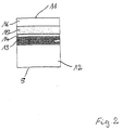
Figur 2- den Aufbau eines Moduls;
- Figur 3
- ein Umformwerkzeug im Einsatz und dessen Aufbau;
Figur 4- ein weiteres Umformwerkzeug und
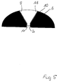
Figur 5- ein weiteres Umformwerkzeug.
- Figure 1
- a forming tool;
- Figure 2
- the construction of a module;
- Figure 3
- a forming tool in use and its structure;
- Figure 4
- another forming tool and
- Figure 5
- another forming tool.
Figur 1 zeigt ein Umformwerkzeug 1 mit einer funktionellen
Oberfläche 10. In das Umformwerkzeug ist eine
Bohrung 2 eingebracht, in die ein Sensormodul 5 eingedreht
ist. Das Sensormodul besitzt einen Grundkörper
12 und eine Oberfläche 11, wobei die Oberfläche
11 mit der Oberfläche 10 formschlüssig abschließt. In
die Oberfläche 11 sind zwei Temperatursensoren 4, 4'
und 4'' nebeneinander eingebracht. Diesen Temperatursensoren
kann nun lokal aufgelöst und kontinuierlich
die Temperatur des Moduls 5 und damit des Werkzeugs 1
an den Oberflächen 10 und 11 überwacht werden. Die
Sensoren 4, 4', 4'' sind über Durchkontaktierungen 3
mit einer gestrichelt eingezeichneten elektrischen
Schaltung 6 zur Auswertung der erfaßten Meßsignale
und weiterhin mit einer Telemetrieschaltung 7 verbunden.
Die Telemetrieschaltung 7 gibt die ausgewerteten
Signale über Koppelstrukturen 9 an eine außerhalb des
Moduls angeordnete Auswerteschaltung weiter.Figure 1 shows a forming
Über die Kopplungsstrukturen 9 werden auch die Sensoren
4, 4'' und 4''' sowie die Schaltungen 6 und 7 mit
elektrischer Energie versorgt.The sensors are also via the
Die Bohrung 2 in dem Werkzeug 10 weist weiterhin eine
Passung 8 auf, so daß das entsprechend ausgeformte
Modul 5 in dem Werkzeug gesichert gehaltert ist.The
Figur 2 zeigt den Aufbau eines Moduls 5, wie es auch
in Figur 1 dargestellt ist. Das Modul 5 weist einen
Grundkörper 12 auf, auf dem eine Isolationsschicht
13, eine sensorische Schicht 14, eine weitere Isolationsschicht
15 und auf dieser eine funktionelle tribologische
Oberflächenschicht 16 aufgebracht sind.
Die Oberflächenschicht 16 bildet dabei die funktionelle
Oberfläche 11 des Moduls, die in gleicher Weise
wie die Oberfläche des Werkzeuges der Formung dient
und daher ebenfalls mit entsprechenden Kräften beaufschlagt
wird. Die Funktionsschicht besteht dabei aus
Titannitrid oder Chromnitrid und bildet den Abschluß
des Schichtsystems. Das Beschichtungsverfahren zur
Herstellung des Moduls ist in diesem Falle so koordiniert,
daß das gesamte System in zwei Prozessen hergestellt
wird, zuzüglich der erforderlichen Strukturierung
der sensorischen Ebene. Da auf das Schichtsystem
extreme mechanische und thermische Belastungen
einwirken, müssen die einzelnen Schichten die dazu
verwendeten Herstellungsverfahren so konzipiert werden,
daß der gesamte Schichtaufbau eine schichttechnologische
Einheit darstellt, die sowohl materialspezifisch
als auch morphologisch optimiert ist.Figure 2 shows the structure of a
Die sensorische Schicht 14 kann dabei vorteilhafterweise
so strukturiert werden, daß sie eine piezoresistive
und/oder piezoelektrische Schicht ist und der
Erzeugung von Druck und/oder temperaturbezogenen Messungen
dient.The
Figur 3 zeigt einen Stempel 20 mit einem Sensormodul
5, wobei das Sensormodul 5 in die druckbeaufschlagte
Oberfläche des Stempels 20 eingebracht ist. Wie in
Figur 3A zu erkennen ist, wird dieser Stempel 20 auf
ein Werkstück 21 gedrückt, das über einem Gesenk 22
angeordnet ist. In diesem Falle ist es mittels des
Moduls 5 möglich, die genauen Druck- und Kraftverhältnisse
an der Stempeloberfläche des Stempels 20 zu
erfassen.FIG. 3 shows a
Figur 3B zeigt einen Ausschnitt aus der Hauptbelastungszone
eines derartigen Stempels, wobei hier der
Ausschnitt genommen wurde, der das Modul 5 enthält.
Auf der Moduloberfläche des Moduls 5 sind dabei zwei
Verschleißsensoren 23, 23' und mittig zu diesen ein
Temperatursensor 4 angeordnet. Die Verschleißsensoren
23, 23' bestehen aus einzelnen Widerstandsbahnen 23a
bis 23e bzw. 23'a bis 23'e. Diese sind so ausgestaltet,
daß mit zunehmendem Verschleiß der Moduloberfläche
11 beginnend mit den Widerstandsbahnen 23e bzw.
23'e die einzelnen Widerstandsbahnen durchtrennt werden
und so eine Verschleißanzeige gegeben ist.Figure 3B shows a section of the main stress zone
of such a stamp, here the
Section was taken, which contains the
Letztlich ist es so möglich, verteilt über die Oberfläche
des Moduls 5 und bei Anwendung mehrerer Module
5 über die Oberfläche des Werkzeugs 20 auch über die
gesamte Oberfläche 10 des Werkzeugs 20 den Verschleiß
der Werkzeugoberfläche während des Einsatzes des
Werkzeuges exakt zu erfassen.Ultimately, it is possible to spread over the surface
of
Figur 4 zeigt ein weiteres Beispiel für ein Werkzeug
1, das eine Bohrung 2 zur Aufnahme eines Sensormoduls
5 aufweist. Das Sensormodul 5 hat eine zylindrische
Form und schließt mit seiner Oberfläche 11 formschlüssig
mit der Oberfläche 10 des Werkzeugs 1 ab.
Die Bohrung 2 ist dabei durch das gesamte Werkzeug
geführt, so daß das Modul 5 rückseitig über die als
Kontaktöffnung 17 dienende Bohrung 2 mit elektrischer
Energie versorgt und die erfaßten Meßwerte von dem
Modul zu einer Auswerteeinheit abgeleitet werden können.Figure 4 shows another example of a
Figur 5 zeigt ein weiteres Beispiel eines Werkzeuges
1, das hier jedoch eine gekrümmte Oberfläche 10 aufweist.
In diese Oberfläche 10 und in das Werkzeug 1
ist eine Bohrung 2 eingebracht, die einen konischen
Querschnitt aufweist und ebenfalls sich bis zur Rückseite
des Werkzeugs 1 fortsetzt. In diese Bohrung 2
ist ein Sensormodul 5 eingebracht, das eine angepaßte
konische Form aufweist und dessen Oberfläche 11 in
gleicher Weise wie die Oberfläche 10 des Werkzeugs 1
gekrümmt ist. Hier ergibt sich wiederum die Möglichkeit,
daß Modul 5 rückseitig über die als Kontaktöffnung
17 ausgeführte Bohrung 2 zu kontaktieren, um den
Sensoren in dem Modul 5 Energie zuzuführen und deren
Meßwerte nach außen abzuleiten.Figure 5 shows another example of a
Durch das erfindungsgemäße modulare Konzept ist es
nunmehr möglich, auf einfache Art und Weise Werkzeuge
für die Umform-, Stanz- und Spritztechnik mit flächenverteilten
Sensoren zu versehen, um lokal aufgelöst
und kontinuierlich verschiedene Zustandsparameter
des Werkzeugs 1 zu erfassen. Dies ist aufgrund
der modularen Bauweise besonders kostengünstig und
einfach durchzuführen.It is due to the modular concept according to the invention
now possible, simple tools
for forming, stamping and spraying technology with surface-distributed
Provide sensors to resolve locally
and continuously different state parameters
to detect the
Claims (16)
gekennzeichnet durch
ein Modul mit einem in das Werkzeug kraft- und formschlüssig integrierbaren Grundkörper, wobei der Grundkörper eine Modul-Oberfläche, die im eingebauten Zustand in die Funktionsoberfläche des Werkzeugs eingebettet und an diese angepaßt ist, und in der Ebene der Oberfläche des Moduls eine flächenhafte Anordnung mehrerer Dünnschichtsensoren aufweist.Tool for forming, stamping or injection molding technology with a functional surface,
marked by
a module with a base body that can be positively and positively integrated into the tool, the base body being a module surface which, in the installed state, is embedded in and adapted to the functional surface of the tool, and a planar arrangement of several in the plane of the surface of the module Has thin film sensors.
dadurch gekennzeichnet, daß
der Grundkörper als Modul in das Werkzeug eingefügt wird und seine Oberfläche gemeinsam mit der Oberfläche des Werkzeugs bearbeitet wird und anschließend auf den Grundkörper, gegebenenfalls im ausgebauten Zustand, mittels Dünnschichttechniken eine Isolationsschicht gefolgt von mindestens einer Sensorschicht sowie eine Funktionsschicht aufgebracht wird, wobei die Schichten durch bekannte Strukturierungsverfahren jeweils vor Aufbringung der folgenden Schicht strukturiert werden.Method for producing a tool according to one of the preceding claims,
characterized in that
the base body is inserted as a module into the tool and its surface is machined together with the surface of the tool and then an insulation layer followed by at least one sensor layer and a functional layer is applied to the base body, optionally in the disassembled state, by means of thin-layer techniques, the layers being known structuring methods are each structured before application of the following layer.
Applications Claiming Priority (2)
| Application Number | Priority Date | Filing Date | Title |
|---|---|---|---|
| DE19925458A DE19925458C2 (en) | 1999-06-02 | 1999-06-02 | Manufacturing process for forming, stamping and injection molding tools |
| DE19925458 | 1999-06-02 |
Publications (3)
| Publication Number | Publication Date |
|---|---|
| EP1057586A2 true EP1057586A2 (en) | 2000-12-06 |
| EP1057586A3 EP1057586A3 (en) | 2001-01-03 |
| EP1057586B1 EP1057586B1 (en) | 2003-04-23 |
Family
ID=7910135
Family Applications (1)
| Application Number | Title | Priority Date | Filing Date |
|---|---|---|---|
| EP00111200A Expired - Lifetime EP1057586B1 (en) | 1999-06-02 | 2000-05-24 | Tool for forming, punching or injection moulding |
Country Status (3)
| Country | Link |
|---|---|
| EP (1) | EP1057586B1 (en) |
| AT (1) | ATE238132T1 (en) |
| DE (2) | DE19925458C2 (en) |
Cited By (15)
| Publication number | Priority date | Publication date | Assignee | Title |
|---|---|---|---|---|
| EP1084806A2 (en) * | 1999-09-17 | 2001-03-21 | Woschnik + Partner Maschinenbau GmbH | Recognition system for the cutting tools of a cutting press |
| WO2002054031A1 (en) * | 1999-11-10 | 2002-07-11 | Fraunhofer-Gesellschaft zur Förderung der angewandten Forschung e.V. | Sensor for determining the state of parameters on mechanical components while using amorphous carbon layers having piezoresistive properties |
| WO2004025234A1 (en) * | 2002-09-10 | 2004-03-25 | Fraunhofer Gesellschaft zur Förderung der angewandten Forschung e.V. | Use of a coating consisting of diamond-like carbon |
| WO2004067225A1 (en) * | 2003-01-29 | 2004-08-12 | Fraunhofer-Gesellschaft zur Förderung der angewandten Forschung e.V. | Device and method for determining the stress placed upon a tool with thin-layer sensors |
| DE10345299B3 (en) * | 2003-09-30 | 2005-07-21 | Giese, Erhard, Dr. | High accuracy, combined pressure- and temperature sensor used in injection mold for plastic, comprises infra red transmission system and sensor, with piezoelectric axial pressure sensor |
| US7010898B2 (en) | 2001-06-20 | 2006-03-14 | Convenience Food Systems Wallau Gmbh & Co. Kg | Tool with a sensor chip |
| WO2010135011A1 (en) * | 2009-05-21 | 2010-11-25 | Siemens Energy, Inc. | Sensor for quantifying increasing reduction wear on a surface |
| WO2011009223A1 (en) | 2009-07-22 | 2011-01-27 | Kistler Holding Ag | Electromechanical joining module having a force transducer |
| DE102010001144A1 (en) * | 2010-01-22 | 2011-07-28 | Fraunhofer-Gesellschaft zur Förderung der angewandten Forschung e.V., 80686 | Mechanical connection component e.g. screw, for monitoring e.g. screw connections in bridge, has wireless interface for wireless detection of information describing mechanical load of component based on electrical property of sensor layer |
| EP2586587A1 (en) * | 2011-10-28 | 2013-05-01 | Gerresheimer Regensburg GmbH | Device and method for producing an object with an injection moulding tool |
| DE102012005555B3 (en) * | 2012-03-21 | 2013-08-22 | Audi Ag | Measuring plate for use in bearing surface of slide damper of press for measuring tension-, pressure- or shear forces, has recesses, in which sensors are mounted under pre-tension for measuring forces by pressure piece |
| EP2928682B1 (en) * | 2012-12-04 | 2018-05-30 | MARPOSS Monitoring Solutions GmbH | Stamping device with a sensor and method for transmitting a sensor signal |
| AT520955A1 (en) * | 2018-01-18 | 2019-09-15 | Engel Austria Gmbh | Measuring device for measuring the distance between two selected points |
| CN112203836A (en) * | 2018-04-05 | 2021-01-08 | 百超激光有限公司 | Component for a machine tool, machine tool and method for detecting wear |
| DE102005033213B4 (en) * | 2004-07-23 | 2021-07-08 | The Minster Machine Co. | Vibration strength monitor for a press die and press with a die system |
Families Citing this family (9)
| Publication number | Priority date | Publication date | Assignee | Title |
|---|---|---|---|---|
| GB2406817B (en) * | 2003-01-10 | 2005-06-15 | Daimler Chrysler Ag | Moulding device |
| DE10300630B4 (en) * | 2003-01-10 | 2005-03-24 | Daimlerchrysler Ag | Molding facility |
| DE102004045783B4 (en) | 2004-09-21 | 2019-09-12 | Peter Schöberl | Thermoforming mold |
| DE102009044838A1 (en) * | 2009-12-09 | 2011-06-16 | Karlsruher Institut für Technologie | Metastabilized, nanostabilized material and process for its preparation |
| DE102009057765A1 (en) * | 2009-12-10 | 2011-06-16 | Fraunhofer-Gesellschaft zur Förderung der angewandten Forschung e.V. | Signal guiding device for manufacturing electrical contact with sensor in deformation tool, has pins extending from front side of body to rear side of body, where device is arranged between shaping area of tool and outer side of tool |
| DE102012022113A1 (en) * | 2012-11-13 | 2014-06-05 | Oerlikon Trading Ag, Trübbach | Piezoelectric force measuring device with integrated wear protection and sliding properties |
| DE102016204796A1 (en) * | 2016-03-23 | 2017-09-28 | Fraunhofer-Gesellschaft zur Förderung der angewandten Forschung e.V. | Measuring element for near-surface measurement of physical quantities, in particular of temperatures, in an at least partially enclosed cavity |
| WO2021192685A1 (en) * | 2020-03-27 | 2021-09-30 | 本田技研工業株式会社 | Measuring device |
| DE102021108310A1 (en) * | 2021-04-01 | 2022-10-06 | Lisa Dräxlmaier GmbH | punching device |
Citations (3)
| Publication number | Priority date | Publication date | Assignee | Title |
|---|---|---|---|---|
| US5176450A (en) * | 1990-11-29 | 1993-01-05 | Rolls-Royce Plc | Fluid temperature measuring device |
| EP0685297A1 (en) * | 1994-05-30 | 1995-12-06 | Fraunhofer-Gesellschaft Zur Förderung Der Angewandten Forschung E.V. | Tool for forming and cutting apparatusses and method of making a coated tool |
| EP0789234A1 (en) * | 1994-10-28 | 1997-08-13 | Komatsu Ltd. | Load sensor substrate and load sensor |
Family Cites Families (4)
| Publication number | Priority date | Publication date | Assignee | Title |
|---|---|---|---|---|
| SE452911B (en) * | 1984-07-06 | 1987-12-21 | Birger Alvelid | PROCEDURE FOR THE MANUFACTURING OF THE MECHANICAL COMPONENTS, ALSO DIFFICULT MECHANICAL COMPONENTS |
| DE4034702A1 (en) * | 1990-10-31 | 1992-05-07 | Siemens Ag | Testing active tools of bending machines, e.g. bending rams - holding tool in measurement position with magnetic field and using two sensors simultaneously in automated process |
| JPH0929358A (en) * | 1995-07-20 | 1997-02-04 | Sanyo Special Steel Co Ltd | Precise shape controlling press die |
| US5622069A (en) * | 1996-03-11 | 1997-04-22 | Oberg Industries, Inc. | Stamping die with attached plc |
-
1999
- 1999-06-02 DE DE19925458A patent/DE19925458C2/en not_active Expired - Fee Related
-
2000
- 2000-05-24 DE DE50001833T patent/DE50001833D1/en not_active Expired - Lifetime
- 2000-05-24 EP EP00111200A patent/EP1057586B1/en not_active Expired - Lifetime
- 2000-05-24 AT AT00111200T patent/ATE238132T1/en not_active IP Right Cessation
Patent Citations (3)
| Publication number | Priority date | Publication date | Assignee | Title |
|---|---|---|---|---|
| US5176450A (en) * | 1990-11-29 | 1993-01-05 | Rolls-Royce Plc | Fluid temperature measuring device |
| EP0685297A1 (en) * | 1994-05-30 | 1995-12-06 | Fraunhofer-Gesellschaft Zur Förderung Der Angewandten Forschung E.V. | Tool for forming and cutting apparatusses and method of making a coated tool |
| EP0789234A1 (en) * | 1994-10-28 | 1997-08-13 | Komatsu Ltd. | Load sensor substrate and load sensor |
Cited By (24)
| Publication number | Priority date | Publication date | Assignee | Title |
|---|---|---|---|---|
| EP1084806A3 (en) * | 1999-09-17 | 2004-01-28 | Heidelberger Druckmaschinen Aktiengesellschaft | Recognition system for the cutting tools of a cutting press |
| EP1084806A2 (en) * | 1999-09-17 | 2001-03-21 | Woschnik + Partner Maschinenbau GmbH | Recognition system for the cutting tools of a cutting press |
| WO2002054031A1 (en) * | 1999-11-10 | 2002-07-11 | Fraunhofer-Gesellschaft zur Förderung der angewandten Forschung e.V. | Sensor for determining the state of parameters on mechanical components while using amorphous carbon layers having piezoresistive properties |
| US7073390B2 (en) | 1999-11-10 | 2006-07-11 | Fraunhofer-Gesellschaft Zur Forderung Der Angewandten Froschung E.V. | Sensor for determining the state of parameters on mechanical components while using amorphous carbon layers having piezoresistive properties |
| US7010898B2 (en) | 2001-06-20 | 2006-03-14 | Convenience Food Systems Wallau Gmbh & Co. Kg | Tool with a sensor chip |
| WO2004025234A1 (en) * | 2002-09-10 | 2004-03-25 | Fraunhofer Gesellschaft zur Förderung der angewandten Forschung e.V. | Use of a coating consisting of diamond-like carbon |
| US8151623B2 (en) | 2002-09-23 | 2012-04-10 | Siemens Energy, Inc. | Sensor for quantifying widening reduction wear on a surface |
| WO2004067225A1 (en) * | 2003-01-29 | 2004-08-12 | Fraunhofer-Gesellschaft zur Förderung der angewandten Forschung e.V. | Device and method for determining the stress placed upon a tool with thin-layer sensors |
| DE10345299B3 (en) * | 2003-09-30 | 2005-07-21 | Giese, Erhard, Dr. | High accuracy, combined pressure- and temperature sensor used in injection mold for plastic, comprises infra red transmission system and sensor, with piezoelectric axial pressure sensor |
| DE102005033213B4 (en) * | 2004-07-23 | 2021-07-08 | The Minster Machine Co. | Vibration strength monitor for a press die and press with a die system |
| WO2010135011A1 (en) * | 2009-05-21 | 2010-11-25 | Siemens Energy, Inc. | Sensor for quantifying increasing reduction wear on a surface |
| WO2011009223A1 (en) | 2009-07-22 | 2011-01-27 | Kistler Holding Ag | Electromechanical joining module having a force transducer |
| CH701524A1 (en) * | 2009-07-22 | 2011-01-31 | Kistler Holding Ag | Electromechanical joining module with load cells. |
| CN102470496A (en) * | 2009-07-22 | 2012-05-23 | 基斯特勒控股公司 | Electromechanical joining module having a force transducer |
| US8733181B2 (en) | 2009-07-22 | 2014-05-27 | Kistler Holding Ag | Electromechanical joining module having a force transducer |
| CN102470496B (en) * | 2009-07-22 | 2015-11-25 | 基斯特勒控股公司 | There is the electric mechanical interface module of force snesor |
| DE102010001144A1 (en) * | 2010-01-22 | 2011-07-28 | Fraunhofer-Gesellschaft zur Förderung der angewandten Forschung e.V., 80686 | Mechanical connection component e.g. screw, for monitoring e.g. screw connections in bridge, has wireless interface for wireless detection of information describing mechanical load of component based on electrical property of sensor layer |
| EP2586587A1 (en) * | 2011-10-28 | 2013-05-01 | Gerresheimer Regensburg GmbH | Device and method for producing an object with an injection moulding tool |
| DE102012005555B3 (en) * | 2012-03-21 | 2013-08-22 | Audi Ag | Measuring plate for use in bearing surface of slide damper of press for measuring tension-, pressure- or shear forces, has recesses, in which sensors are mounted under pre-tension for measuring forces by pressure piece |
| EP2928682B1 (en) * | 2012-12-04 | 2018-05-30 | MARPOSS Monitoring Solutions GmbH | Stamping device with a sensor and method for transmitting a sensor signal |
| AT520955A1 (en) * | 2018-01-18 | 2019-09-15 | Engel Austria Gmbh | Measuring device for measuring the distance between two selected points |
| AT520955B1 (en) * | 2018-01-18 | 2020-08-15 | Engel Austria Gmbh | Measuring device for measuring the distance between two selected points |
| US11016115B2 (en) | 2018-01-18 | 2021-05-25 | Engel Austria Gmbh | Measuring device for measuring the space of two selected points on a shaping machine or handling apparatus |
| CN112203836A (en) * | 2018-04-05 | 2021-01-08 | 百超激光有限公司 | Component for a machine tool, machine tool and method for detecting wear |
Also Published As
| Publication number | Publication date |
|---|---|
| DE19925458C2 (en) | 2002-07-18 |
| DE19925458A1 (en) | 2000-12-14 |
| ATE238132T1 (en) | 2003-05-15 |
| DE50001833D1 (en) | 2003-05-28 |
| EP1057586B1 (en) | 2003-04-23 |
| EP1057586A3 (en) | 2001-01-03 |
Similar Documents
| Publication | Publication Date | Title |
|---|---|---|
| EP1057586B1 (en) | Tool for forming, punching or injection moulding | |
| EP2013598B1 (en) | Force-sensing device for measuring force on solid state actuators, method for measuring force, as well as use of force-sensing device | |
| DE10017572B4 (en) | Rolling bearings with remote sensing units | |
| DE19925460C2 (en) | Sliding and / or rolling pairings with thin-film sensors | |
| DE102015100655A1 (en) | Linear guide device for a feed axis of a machine tool | |
| EP1678474A2 (en) | Device for determining strains on fiber composite components | |
| EP3211396B1 (en) | Sensor for integral or spatially resolved measuring of extensions based on pre-damaged carbon fibres | |
| DE102009053043A1 (en) | Load cell for measuring the injection force during injection molding | |
| EP1888293B1 (en) | Optical element and method for recording beam parameters, comprising a temperature sensor provided in the form of a pixel matrix | |
| DE10243095B4 (en) | Rolling bearings with integrated condition measurement | |
| EP2504590A1 (en) | Bearing device having a sensor for measuring the vertical bearing force of a rotating shaft | |
| WO2011039566A1 (en) | Measuring device allowing detection of deformations | |
| EP3028023B1 (en) | Method for producing a force-measuring element | |
| WO2011026616A1 (en) | Device for measuring and/or detecting distances and distance changes and device for measuring and/or detecting mechanical loads | |
| DE19958903A1 (en) | Force sensor integrated in the actuator | |
| DE19620459B4 (en) | Semiconductor accelerometer and method for evaluating the properties of a semiconductor accelerometer | |
| DE102006007406B3 (en) | Thrust measuring bridge for technical measurement detection of thrust of e.g. aircraft engine, has thrust determining device, which is provided for determination of thrust of engine from parameter | |
| EP2585802A1 (en) | Piezoresistive force sensor | |
| DE102010054970B4 (en) | Device for converting an expansion and / or compression into an electrical signal, in particular a strain gauge film | |
| DE4309530C2 (en) | Device for the dynamic mechanical analysis of test specimens | |
| WO2011039567A1 (en) | Measuring device comprising a detunable resistor | |
| EP1834162B1 (en) | Microsystem component with a device deformable under the influence of temperature changes | |
| DE102021005558B3 (en) | Measuring roller for determining a property of a strip-shaped product guided over a measuring roller, and use of such a measuring roller | |
| DE102016111879A1 (en) | Unidirectionally sensitive sensor for measuring deformations and brake with such a sensor | |
| DE102022130427B3 (en) | Device for holding, storing and/or guiding a rod-shaped element made of a magnetic shape memory alloy |
Legal Events
| Date | Code | Title | Description |
|---|---|---|---|
| PUAI | Public reference made under article 153(3) epc to a published international application that has entered the european phase |
Free format text: ORIGINAL CODE: 0009012 |
|
| PUAL | Search report despatched |
Free format text: ORIGINAL CODE: 0009013 |
|
| AK | Designated contracting states |
Kind code of ref document: A2 Designated state(s): AT BE CH CY DE DK ES FI FR GB GR IE IT LI LU MC NL PT SE |
|
| AX | Request for extension of the european patent |
Free format text: AL;LT;LV;MK;RO;SI |
|
| AK | Designated contracting states |
Kind code of ref document: A3 Designated state(s): AT BE CH CY DE DK ES FI FR GB GR IE IT LI LU MC NL PT SE |
|
| AX | Request for extension of the european patent |
Free format text: AL;LT;LV;MK;RO;SI |
|
| 17P | Request for examination filed |
Effective date: 20010120 |
|
| AKX | Designation fees paid |
Free format text: AT BE CH CY DE DK ES FI FR GB GR IE IT LI LU MC NL PT SE |
|
| GRAH | Despatch of communication of intention to grant a patent |
Free format text: ORIGINAL CODE: EPIDOS IGRA |
|
| GRAH | Despatch of communication of intention to grant a patent |
Free format text: ORIGINAL CODE: EPIDOS IGRA |
|
| GRAA | (expected) grant |
Free format text: ORIGINAL CODE: 0009210 |
|
| AK | Designated contracting states |
Designated state(s): AT BE CH CY DE DK ES FI FR GB GR IE IT LI LU MC NL PT SE |
|
| PG25 | Lapsed in a contracting state [announced via postgrant information from national office to epo] |
Ref country code: FI Free format text: LAPSE BECAUSE OF FAILURE TO SUBMIT A TRANSLATION OF THE DESCRIPTION OR TO PAY THE FEE WITHIN THE PRESCRIBED TIME-LIMIT Effective date: 20030423 Ref country code: IE Free format text: LAPSE BECAUSE OF NON-PAYMENT OF DUE FEES Effective date: 20030423 Ref country code: NL Free format text: LAPSE BECAUSE OF FAILURE TO SUBMIT A TRANSLATION OF THE DESCRIPTION OR TO PAY THE FEE WITHIN THE PRESCRIBED TIME-LIMIT Effective date: 20030423 |
|
| REG | Reference to a national code |
Ref country code: GB Ref legal event code: FG4D Free format text: NOT ENGLISH |
|
| REG | Reference to a national code |
Ref country code: CH Ref legal event code: EP |
|
| PGFP | Annual fee paid to national office [announced via postgrant information from national office to epo] |
Ref country code: AT Payment date: 20030523 Year of fee payment: 4 |
|
| PG25 | Lapsed in a contracting state [announced via postgrant information from national office to epo] |
Ref country code: LU Free format text: LAPSE BECAUSE OF NON-PAYMENT OF DUE FEES Effective date: 20030524 Ref country code: CY Free format text: LAPSE BECAUSE OF FAILURE TO SUBMIT A TRANSLATION OF THE DESCRIPTION OR TO PAY THE FEE WITHIN THE PRESCRIBED TIME-LIMIT Effective date: 20030524 |
|
| REF | Corresponds to: |
Ref document number: 50001833 Country of ref document: DE Date of ref document: 20030528 Kind code of ref document: P |
|
| REG | Reference to a national code |
Ref country code: IE Ref legal event code: FG4D Free format text: GERMAN |
|
| PG25 | Lapsed in a contracting state [announced via postgrant information from national office to epo] |
Ref country code: BE Free format text: LAPSE BECAUSE OF NON-PAYMENT OF DUE FEES Effective date: 20030531 Ref country code: MC Free format text: LAPSE BECAUSE OF NON-PAYMENT OF DUE FEES Effective date: 20030531 |
|
| PG25 | Lapsed in a contracting state [announced via postgrant information from national office to epo] |
Ref country code: GR Free format text: LAPSE BECAUSE OF FAILURE TO SUBMIT A TRANSLATION OF THE DESCRIPTION OR TO PAY THE FEE WITHIN THE PRESCRIBED TIME-LIMIT Effective date: 20030723 Ref country code: SE Free format text: LAPSE BECAUSE OF FAILURE TO SUBMIT A TRANSLATION OF THE DESCRIPTION OR TO PAY THE FEE WITHIN THE PRESCRIBED TIME-LIMIT Effective date: 20030723 Ref country code: PT Free format text: LAPSE BECAUSE OF FAILURE TO SUBMIT A TRANSLATION OF THE DESCRIPTION OR TO PAY THE FEE WITHIN THE PRESCRIBED TIME-LIMIT Effective date: 20030723 Ref country code: DK Free format text: LAPSE BECAUSE OF FAILURE TO SUBMIT A TRANSLATION OF THE DESCRIPTION OR TO PAY THE FEE WITHIN THE PRESCRIBED TIME-LIMIT Effective date: 20030723 |
|
| GBT | Gb: translation of ep patent filed (gb section 77(6)(a)/1977) | ||
| NLV1 | Nl: lapsed or annulled due to failure to fulfill the requirements of art. 29p and 29m of the patents act | ||
| PG25 | Lapsed in a contracting state [announced via postgrant information from national office to epo] |
Ref country code: ES Free format text: LAPSE BECAUSE OF FAILURE TO SUBMIT A TRANSLATION OF THE DESCRIPTION OR TO PAY THE FEE WITHIN THE PRESCRIBED TIME-LIMIT Effective date: 20031030 |
|
| RAP2 | Party data changed (patent owner data changed or rights of a patent transferred) |
Owner name: FRAUNHOFER-GESELLSCHAFT ZUR FOERDERUNG DERANGEWAND |
|
| REG | Reference to a national code |
Ref country code: IE Ref legal event code: FD4D Ref document number: 1057586E Country of ref document: IE |
|
| BERE | Be: lapsed |
Owner name: *FRAUNHOFER-GESELLSCHAFT ZUR FORDERUNG DER ANGEWAN Effective date: 20030531 |
|
| ET | Fr: translation filed | ||
| PLBE | No opposition filed within time limit |
Free format text: ORIGINAL CODE: 0009261 |
|
| STAA | Information on the status of an ep patent application or granted ep patent |
Free format text: STATUS: NO OPPOSITION FILED WITHIN TIME LIMIT |
|
| 26N | No opposition filed |
Effective date: 20040126 |
|
| PG25 | Lapsed in a contracting state [announced via postgrant information from national office to epo] |
Ref country code: AT Free format text: LAPSE BECAUSE OF NON-PAYMENT OF DUE FEES Effective date: 20040524 |
|
| PG25 | Lapsed in a contracting state [announced via postgrant information from national office to epo] |
Ref country code: LI Free format text: LAPSE BECAUSE OF NON-PAYMENT OF DUE FEES Effective date: 20040531 Ref country code: CH Free format text: LAPSE BECAUSE OF NON-PAYMENT OF DUE FEES Effective date: 20040531 |
|
| REG | Reference to a national code |
Ref country code: CH Ref legal event code: PL |
|
| PGFP | Annual fee paid to national office [announced via postgrant information from national office to epo] |
Ref country code: GB Payment date: 20120522 Year of fee payment: 13 Ref country code: FR Payment date: 20120608 Year of fee payment: 13 |
|
| PGFP | Annual fee paid to national office [announced via postgrant information from national office to epo] |
Ref country code: IT Payment date: 20120522 Year of fee payment: 13 |
|
| GBPC | Gb: european patent ceased through non-payment of renewal fee |
Effective date: 20130524 |
|
| PG25 | Lapsed in a contracting state [announced via postgrant information from national office to epo] |
Ref country code: IT Free format text: LAPSE BECAUSE OF NON-PAYMENT OF DUE FEES Effective date: 20130524 |
|
| REG | Reference to a national code |
Ref country code: FR Ref legal event code: ST Effective date: 20140131 |
|
| PG25 | Lapsed in a contracting state [announced via postgrant information from national office to epo] |
Ref country code: GB Free format text: LAPSE BECAUSE OF NON-PAYMENT OF DUE FEES Effective date: 20130524 |
|
| PG25 | Lapsed in a contracting state [announced via postgrant information from national office to epo] |
Ref country code: FR Free format text: LAPSE BECAUSE OF NON-PAYMENT OF DUE FEES Effective date: 20130531 |
|
| PGFP | Annual fee paid to national office [announced via postgrant information from national office to epo] |
Ref country code: DE Payment date: 20140521 Year of fee payment: 15 |
|
| REG | Reference to a national code |
Ref country code: DE Ref legal event code: R119 Ref document number: 50001833 Country of ref document: DE |
|
| PG25 | Lapsed in a contracting state [announced via postgrant information from national office to epo] |
Ref country code: DE Free format text: LAPSE BECAUSE OF NON-PAYMENT OF DUE FEES Effective date: 20151201 |