EP2928339B1 - Uhrband, befestigungssystem für ein uhrband und entsprechende uhr - Google Patents
Uhrband, befestigungssystem für ein uhrband und entsprechende uhr Download PDFInfo
- Publication number
- EP2928339B1 EP2928339B1 EP12816513.1A EP12816513A EP2928339B1 EP 2928339 B1 EP2928339 B1 EP 2928339B1 EP 12816513 A EP12816513 A EP 12816513A EP 2928339 B1 EP2928339 B1 EP 2928339B1
- Authority
- EP
- European Patent Office
- Prior art keywords
- strap
- section
- male
- female
- holes
- Prior art date
- Legal status (The legal status is an assumption and is not a legal conclusion. Google has not performed a legal analysis and makes no representation as to the accuracy of the status listed.)
- Not-in-force
Links
- 210000000707 wrist Anatomy 0.000 claims description 43
- 239000010985 leather Substances 0.000 claims description 9
- 239000004033 plastic Substances 0.000 claims description 4
- 239000005060 rubber Substances 0.000 claims description 4
- 239000000956 alloy Substances 0.000 claims description 3
- 229910045601 alloy Inorganic materials 0.000 claims description 3
- 239000007769 metal material Substances 0.000 claims description 3
- 230000002452 interceptive effect Effects 0.000 description 2
- 230000000670 limiting effect Effects 0.000 description 2
- 239000000463 material Substances 0.000 description 2
- 230000000284 resting effect Effects 0.000 description 2
- 230000003313 weakening effect Effects 0.000 description 2
- 238000005299 abrasion Methods 0.000 description 1
- 230000004075 alteration Effects 0.000 description 1
- 230000000694 effects Effects 0.000 description 1
- 238000000605 extraction Methods 0.000 description 1
- 230000037431 insertion Effects 0.000 description 1
- 238000003780 insertion Methods 0.000 description 1
- 239000002184 metal Substances 0.000 description 1
- 230000036961 partial effect Effects 0.000 description 1
- 239000002861 polymer material Substances 0.000 description 1
- 230000000717 retained effect Effects 0.000 description 1
- 230000000007 visual effect Effects 0.000 description 1
Images


Classifications
-
- A—HUMAN NECESSITIES
- A44—HABERDASHERY; JEWELLERY
- A44C—PERSONAL ADORNMENTS, e.g. JEWELLERY; COINS
- A44C5/00—Bracelets; Wrist-watch straps; Fastenings for bracelets or wrist-watch straps
- A44C5/18—Fasteners for straps, chains or the like
- A44C5/20—Fasteners for straps, chains or the like for open straps, chains or the like
- A44C5/2071—Fasteners for straps, chains or the like for open straps, chains or the like with the two ends of the strap or chain overlapping each other and fastened by an action perpendicularly to the main plane of these two ends
-
- A—HUMAN NECESSITIES
- A44—HABERDASHERY; JEWELLERY
- A44B—BUTTONS, PINS, BUCKLES, SLIDE FASTENERS, OR THE LIKE
- A44B11/00—Buckles; Similar fasteners for interconnecting straps or the like, e.g. for safety belts
- A44B11/25—Buckles; Similar fasteners for interconnecting straps or the like, e.g. for safety belts with two or more separable parts
- A44B11/26—Buckles; Similar fasteners for interconnecting straps or the like, e.g. for safety belts with two or more separable parts with push-button fastenings
- A44B11/266—Buckles; Similar fasteners for interconnecting straps or the like, e.g. for safety belts with two or more separable parts with push-button fastenings with at least one push-button acting parallel to the main plane of the buckle and perpendicularly to the direction of the fastening action
-
- A—HUMAN NECESSITIES
- A44—HABERDASHERY; JEWELLERY
- A44C—PERSONAL ADORNMENTS, e.g. JEWELLERY; COINS
- A44C5/00—Bracelets; Wrist-watch straps; Fastenings for bracelets or wrist-watch straps
- A44C5/18—Fasteners for straps, chains or the like
- A44C5/185—Attachment of fasteners to straps or chains
-
- A—HUMAN NECESSITIES
- A44—HABERDASHERY; JEWELLERY
- A44B—BUTTONS, PINS, BUCKLES, SLIDE FASTENERS, OR THE LIKE
- A44B17/00—Press-button or snap fasteners
- A44B17/0011—Press-button fasteners in which the elastic retaining action is obtained by a spring working in the plane of the fastener
- A44B17/0017—Their fastening
-
- A—HUMAN NECESSITIES
- A44—HABERDASHERY; JEWELLERY
- A44D—INDEXING SCHEME RELATING TO BUTTONS, PINS, BUCKLES OR SLIDE FASTENERS, AND TO JEWELLERY, BRACELETS OR OTHER PERSONAL ADORNMENTS
- A44D2201/00—Fastening by snap action
-
- Y—GENERAL TAGGING OF NEW TECHNOLOGICAL DEVELOPMENTS; GENERAL TAGGING OF CROSS-SECTIONAL TECHNOLOGIES SPANNING OVER SEVERAL SECTIONS OF THE IPC; TECHNICAL SUBJECTS COVERED BY FORMER USPC CROSS-REFERENCE ART COLLECTIONS [XRACs] AND DIGESTS
- Y10—TECHNICAL SUBJECTS COVERED BY FORMER USPC
- Y10T—TECHNICAL SUBJECTS COVERED BY FORMER US CLASSIFICATION
- Y10T24/00—Buckles, buttons, clasps, etc.
- Y10T24/45—Separable-fastener or required component thereof [e.g., projection and cavity to complete interlock]
- Y10T24/45152—Each mating member having similarly shaped, sized, and operated interlocking or intermeshable face
- Y10T24/45183—Clasp [e.g., spring type]
- Y10T24/45188—Clasp [e.g., spring type] for jewelry [e.g., buckle type]
-
- Y—GENERAL TAGGING OF NEW TECHNOLOGICAL DEVELOPMENTS; GENERAL TAGGING OF CROSS-SECTIONAL TECHNOLOGIES SPANNING OVER SEVERAL SECTIONS OF THE IPC; TECHNICAL SUBJECTS COVERED BY FORMER USPC CROSS-REFERENCE ART COLLECTIONS [XRACs] AND DIGESTS
- Y10—TECHNICAL SUBJECTS COVERED BY FORMER USPC
- Y10T—TECHNICAL SUBJECTS COVERED BY FORMER US CLASSIFICATION
- Y10T24/00—Buckles, buttons, clasps, etc.
- Y10T24/45—Separable-fastener or required component thereof [e.g., projection and cavity to complete interlock]
- Y10T24/45152—Each mating member having similarly shaped, sized, and operated interlocking or intermeshable face
- Y10T24/45183—Clasp [e.g., spring type]
- Y10T24/45194—Clasp [e.g., spring type] for belt or strap
-
- Y—GENERAL TAGGING OF NEW TECHNOLOGICAL DEVELOPMENTS; GENERAL TAGGING OF CROSS-SECTIONAL TECHNOLOGIES SPANNING OVER SEVERAL SECTIONS OF THE IPC; TECHNICAL SUBJECTS COVERED BY FORMER USPC CROSS-REFERENCE ART COLLECTIONS [XRACs] AND DIGESTS
- Y10—TECHNICAL SUBJECTS COVERED BY FORMER USPC
- Y10T—TECHNICAL SUBJECTS COVERED BY FORMER US CLASSIFICATION
- Y10T24/00—Buckles, buttons, clasps, etc.
- Y10T24/45—Separable-fastener or required component thereof [e.g., projection and cavity to complete interlock]
- Y10T24/45225—Separable-fastener or required component thereof [e.g., projection and cavity to complete interlock] including member having distinct formations and mating member selectively interlocking therewith
- Y10T24/45262—Pin, post and receiver
-
- Y—GENERAL TAGGING OF NEW TECHNOLOGICAL DEVELOPMENTS; GENERAL TAGGING OF CROSS-SECTIONAL TECHNOLOGIES SPANNING OVER SEVERAL SECTIONS OF THE IPC; TECHNICAL SUBJECTS COVERED BY FORMER USPC CROSS-REFERENCE ART COLLECTIONS [XRACs] AND DIGESTS
- Y10—TECHNICAL SUBJECTS COVERED BY FORMER USPC
- Y10T—TECHNICAL SUBJECTS COVERED BY FORMER US CLASSIFICATION
- Y10T24/00—Buckles, buttons, clasps, etc.
- Y10T24/47—Strap-end-attaching devices
- Y10T24/4782—Watch strap
Definitions
- the present invention relates to a watchstrap with two separate strap sections or segments, which can be fastened one on the other.
- the invention relates to a strap for a wrist watch in which a first strap section has one or more holes and the end of a second strap section is fastened in correspondence of a hole, so as to fasten the watch around the wrist.
- the present invention also relates to a system for fastening a watchstrap of the type indicated above.
- the invention also relates to a watch to which the aforementioned strap and fastening system are fitted.
- a watchstrap for example a strap made of leather or hide, has two strap segments or sections, the ends of which can be arranged on top of each other, in order to attach the watch to a wrist, or can be separated, in order to remove the watch from the wrist.
- a first section of the strap has a plurality of holes along a central line, at a predefined interval from each other, and a second section of the strap is provided, at an end A thereof, with a buckle and a tongue.
- An opposite end B of the second strap section may be fixed to the case of a watch, in a manner known per se, as may be one of the ends of the first strap section.
- the free end of the first strap section is passed through the buckle and then the strap is tightened around the wrist, by pulling the buckle towards the watch case, by means of the first strap section, and finally the strap is fastened by inserting the tongue into one of the holes of the first strap section.
- the choice of the hole inside which the tongue is inserted allows the strap to be fastened in a more or less loose manner.
- Such a strap has optimum characteristics in terms of versatility and ease of use, it being simple to adjust its width by inserting the tongue into one of the available holes, without performing any structural adjustments of the strap or the watch itself. This simple adjustment is greatly appreciated because, with time, it may happen that one wishes to wear the watch in a more or less loose manner on the wrist or various persons with different wrist sizes might wish to wear the same watch, without complex adjustment or replacement of the strap being required.
- the metal straps consisting of a plurality of links where adjustment is performed by removing a number of links, said adjustment being much more complicated than in the case of hide or leather straps.
- the known strap is greatly appreciated among other things because the two separate sections allow the watch to be attached around the wrist without having to pass it over the hand, something which is instead necessary when putting on a watch with a deployment clasp, this hinge-type fastening system not being liked by persons with a large hand.
- the closed straps are formed essentially by a closed ring with an articulated part which allows its cross-section to be varied, increasing it so as to allow the hand to be inserted or removed from the strap, or reducing it, so as to tighten and close the strap around the wrist.
- the two-section strap made of hide or leather has a number of drawbacks.
- the strap must be tightened around the wrist by pulling the buckle by means of the first strap section and this operation may result in an abrasive action on the strap, which in the long run damages the leather, hide or material from which the strap is made.
- the aforementioned deformation also causes structural weakening and alteration of the appearance. Sometimes the form of the tongue remains impressed as a darker zone on the first hide or leather section, creating an undesirable aesthetic effect.
- the strap may weaken, break or suffer structural damage thereto, resulting in the worst case in loss of the watch or damage, as a result of it to falling onto the ground.
- the technical problem forming the basis of the present invention is that of devising a watchstrap which retains the same characteristics of versatility and ease of use of the known strap, but which does not have the drawbacks mentioned above and in particular is not subject to visual or structural damage as a result of the opening and closing operations and which is very simple and safe to use.
- the proposed solution forming the basis of the present invention is that of fitting to one of the holes available on a first section of a strap, for example a strap made of hide, leather, rubber or plastic, a male part or female part of a male/female fastening system, and fitting onto a second separate section of the strap the other, female or male, part of the fastening system.
- attachment of the male part or female part to one of the holes of the first section is removable and allows changes of the width of the strap, by fitting the male part or female part to another hole.
- the strap maintains a preset width, thus avoiding manual adjustment whenever the watch is worn.
- the male or female part remains fixed to the hole even after removing the watch from the wrist, allowing substantially automatic, rapid and pre-adjusted fastening of the strap.
- the strap no longer requires the tongue and the buckle, and manual adjustment thereof is no longer required whenever the watch is put on, thus preventing any abrasion of the strap caused by rubbing with the buckle or the tongue, or creasing, structural damage or aesthetic damage,
- the technical problem may be solved also by a strap in which the male part of a male/female fastening system is fitted to the second section and the female part is fitted to the first section with the holes.
- the strap comprises two separate strap segments or sections, a first section comprising one or more holes in correspondence to which an end of a second section is arranged, so as to fasten the strap and the watch around a wrist, and is characterized in that it comprises a fastening system with a male part, fixed onto the second section and a female part, removably fixed through one of said holes to the first section, so as to set a predefined width of the strap, the female part being provided with a receiving seat for snap-engagement of the male part, for an automatic and pre-adjusted fastening of the strap around the wrist, and including means for releasing the male part, so that the strap may be opened; watchstrap (1) comprising two separate strap sections (2, 3), a first section (2)
- the description below refers to a preferred embodiment in which the male part is fitted to the first strap section (section with the holes) but it is evident that fitting of the male and female parts onto the strap sections may be reversed, forming a strap which nevertheless falls within the scope of protection of the present application.
- fastening around the wrist my be speeded up, since the width is already adjusted, and it is merely needed to apply a light pressure onto the male part (on the first strap section) or onto the female part (by means of the second strap section) in order to join together and close the parts, without creasing of the strap or friction against a buckle.
- the male part comprises a male element and a female element which can be removably joined together, at least one portion between the male element and the female element passes through the holes of the first section and both said male element and female element have a respective head with a cross-section larger than the cross-section of the holes, which prevents the elements from passing through the hole and forms a surface for resting on the first section.
- the heads of the male and female elements are on opposite sides of the first strap section.
- the width of the strap which is required for example when the watch is worn by another person or because one wishes to loosen it or tighten it around one's wrist, it is sufficient to remove the male element and the female element from the hole to which they are fixed and fit them to another hole on the first strap section.
- the male part comprises a tip which during use is directed towards the wrist and projects from the first strap section.
- This tip can be snap-engaged, preferably in a concealed manner, inside the receiving seat of the female part of the fastening system.
- a structure simplifies fastening which is achieved by means of a slight pressure on the male part, for example applied on the visible side of the first strap section, which allows the tip to snap engage inside the female part, while the latter is supported and in contact with the wrist.
- the tip is formed by the head of the male element, while the head of the female element is substantially coplanar with the first section, preferably circular, and visible, during use of the strap on the wrist.
- the tip is preferably rounded.
- the head of the male element has substantially a mushroom-like form, with a shank of smaller cross-section, preferably passing through the hole in the first strap section, and the tip rounded and larger than the shank.
- the receiving seat in the female part has an opening with a cross-section substantially equal to a cross-section of the tip of the male element and is associated with a movable plate which, owing to the action of a resilient means (for example a spring), engages at least partly inside the opening.
- the rounded tip In order to fasten the strap, the rounded tip is first aligned with the receiving seat of the female part and then pressed inside it, so as to move back the plate from the opening of the seat, thus compressing the spring; when the tip has been inserted, the plate moves forward again inside the opening, owing to the thrust of the spring, coming into contact with the shank and locking the tip in the seat. In this way the plate acts as safety device for the fastening system.
- the plate is structurally associated with release means, which can be operated manually, so as to release the male element, moving the plate back from the seat.
- the possible systems for mechanically joining together the male part and female part may also be varied.
- the male element and the female element consist of a screw and a female thread which can be screwed into one another, preferably along a section thereof which involves the holes in the first section and its entire thickness.
- the male part and the female part of the fastening system are made of metallic material or an alloy.
- the first and second strap sections are made of hide or leather or flexible material, for example rubber, plastic or polymer material.
- the female part forms a terminal part of the second strap section, at the end thereof to which it is fixed.
- a fastening system for a watchstrap characterized in that it comprises a male part and a female part.
- either one of the male part and female part is removably fixed through a hole in a first section of the strap provided with a plurality of holes for setting a predefined width of the strap, and the other one of the male part and female part is fixed onto a second and separate section of the strap.
- the female part has a receiving seat for snap-engagement of the male part, for automatic and pre-adjusted fastening of the strap around the wrist, and comprises means for releasing the male part, to open the strap.
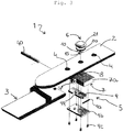
- the reference number 1 schematically denotes a watchstrap, in particular a watchstrap for a wrist watch, of the type comprising two different strap segments or sections 2, 3, each of which is designed to be fixed at one of its end to a watch structure, by means of fixing means.
- These means consist for example of a pin which is inserted inside a slit formed at the end of the section 2, 3, for example formed by means of folding over of the section onto itself; the pin has two opposite ends which emerge from the strap section and are fixed between two seats formed in the watch case.
- the strap is for example made of hide or leather, but may also be made of plastic or rubber, as will become clear from the description below.
- a first strap section 2 has one or more holes 4 which are formed in the thickness of the strap and in correspondence to which the end of a second section 3 is fastened, to fix the strap and the watch around a wrist.
- the holes 4 are not formed along the entire length of the strap; for example, a first hole 4 is near the end 2x of the first section 2 opposite to the end 2y where the section 2 is fixed to the watch structure; the holes have a predefined interval which allows the strap to be adjusted between a maximum width, obtained by aligning the end of the second section with the first hole 4, and a minimum width, obtained by aligning the end of the second section with the last of the holes 4.
- a fastening system 5 for the strap comprises a male part 6, which is removably fixed to the first section 2 via one of the holes 4, and a female part 7, which is fixed to the second section 3, so as to receive the male part and fasten together the two sections in a predefined width of the strap.
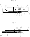
- Figures 1 and 2 show the male part and female part during fastening of the strap.
- the male part is fixed once only to the hole 4, thus setting a width which is maintained between successive strap opening and closing operations.
- the male part may be removed and the width may therefore be varied if required, for example if the user wishes to widen the strap, following slight variations in the size of the wrist, or if a different user intends wearing the watch or immediately after purchase.
- closing and opening are performed avoiding any structural stress affecting the strap, by moving the two sections towards each other and joining the male part together with the female part, without folding the sections or causing them to rub together, thus avoiding structural weakening of the strap.
- the female part 7 is provided with a receiving seat 8 for snap-engagement of the male part 6, for automatic fastening, and comprises release means 9 for the male part 6, for opening of the strap.
- This figure shows a non-limiting example of embodiment of the fastening system 5, in which the receiving seat 8 for the male part is formed in a structural block 7a of the female part 7 and is associated with a lever 9.
- the lever 9 is provided with a hole 99 and is kept by means of resilient means in a position partially interfering with the passing movement of the male part 6 inside the receiving seat 8, for example by means of a spring 9a.
- the lever 9 is movable and accessible on the outside of female part, so as to centre the hole 99 with respect to the receiving seat 8, allowing the male part 6 to be received inside the receiving seat 8.
- a tip 15 of the male part is aligned inside the receiving seat 8 and a light pressure is applied onto the male part 6 in order to displace the lever 9 by means of the tip 15, overcoming the resilient means and causing the lever 9 to move backwards, thus centring the hole 99 with the receiving seat 9 and allowing the male part 6 to enter into the receiving seat 8 in a predefined manner.
- the lever 9 returns automatically into the position where it partially interferes owing to the action of the resilient means, and prevents the male part 6 from coming out of the receiving seat 8, retaining the tip 15 thereof.
- the tip 15 has a substantially conical, preferably rounded, cross-section, and the male part has a shank with a smaller cross-section than a larger base of the tip 15; when retracted into the partly interfering position, the plate 9 engages with the base of the conical tip 15 and prevents the male part 6 from coming out.
- a lug 9d which is accessible on the outside of the female part 7, allows a pressure to be applied onto the lever 9, which overcomes the force of the resilient means, centring the hole 99 with the receiving seat 8, and therefore allowing extraction of the male part from the female part.
- the male part 6 and the female part 7 are made of metallic material or an alloy.
- the structural stresses of such a fastening system 5 affect only the male part and the female part and not the strap.
- the male part 6 comprises a male element 10 and a female element 20 which can be removably joined together, at least one of the male element and female element has a portion, also called shank, which passes through the holes 4, so as to fix the male part 6 to the first strap section, and both the male element and female element have a respective head 11, 21 with a cross-section greater than the cross-section of the holes 4, in order to prevent the male part from coming out of the holes of the first section.
- the heads 11, 21 are on opposite sides 2A, 2B of the first strap section 2.
- this shows an embodiment of the male part 6, in which the female element 20 has a head 21 and a female thread 23, and the male element 10 has a head 11 and a screw 13.
- the female thread 23 has a length and a diameter substantially corresponding to a thickness and a diameter of the holes 4 in the strap, for example 2 mm thickness and diameter, and can be inserted inside the hole 4, so as to occupy it completely, the head 21 resting on one side of the first strap section.
- the screw 13 of the male element is screwed into the female thread 23 of the female element until the head 11 of the male element is arranged against an opposite side of the first section, substantially gripping the strap between the heads 11 and 21.
- Figure 5 shows in schematic form the male part 6 and the female part 7 during fastening.
- the screw 13 of the male element 10 is not visible because it is engaged inside the female thread 23 of the female element 20; the strap is not shown and is intended to occupy the space between the heads 11 and 21.
- the system for joining together the male element and the female element is not of the screw/female thread type but is a different type of mechanical joining system which substantially comprises a shaft as a male element and a hole as a female element.
- the tip of the male part for example the tip 15 in Figure 4 , is directed during use towards the wrist, projects from the first strap section and can be snap-engaged, preferably in a hidden way, inside the receiving seat 8 of the female part 7 of the fastening system 5.
- the tip 15 is preferably formed on the head 11 of the male element 10.
- the remaining portion of the head 11 is arranged against and substantially coplanar with the first section 2, being preferably circular, and not visible, when the strap is worn on the wrist, since it faces the wrist.
- the tip 15 of the male element has a mushroom-like form, with the terminal part having a larger cross-section, designed to locate against the release means 9 of the female part inside the receiving seat 8, and the shank 16 having a smaller cross-section.
- the head 21 of the female element is also arranged against and substantially coplanar with the first section 2, being preferably circular, but visible, when the strap is worn on the wrist, since it is arranged on the opposite side of the first section 2 with respect to the head 11 of the male element 10.
- the female part 7 forms a terminal part 3T of the second section 3 of the strap.
- a pin 40 can be inserted through a slit of the terminal part 3T, for example formed by means of folding back thereof, passing through a ring 41 of the female part 7.
- the female element and not the male element, may incorporate or form the tip 15 which can be inserted in the female part 7 of the fastening system.
- a strap may still comprise two separate strap sections 2, 3, a first section 2 comprising one or more holes 4 opposite which the end of a second section 3 may be fastened, in order to fasten the strap and the watch around a wrist.
- the fastening system 5 has a male part, fixed onto the second section, and a female part, removably fixed through one of said holes 4 to the first section 2, so as to set a predefined width of the strap, and provided with a receiving seat 8 for snap-engagement of the male part, for automatic and pre-adjusted fastening of the strap around the wrist, said female part including means 9 for releasing the male part, so that the strap may be opened.
- the female part comprises a male element and female element which can be removably joined together, at least one of them passing through the holes 4 and both comprising a respective head with a larger cross-section than the holes 4, so as to prevent the female part from coming out of the of the hole in the first section.
- the heads are on opposite sides 2A, 2B of the first strap section 2, which is gripped between them.
- the technical problem forming the basis of the present invention is also solved by a fastening system 5 for a watchstrap.
- the system comprises a male part 6 and a female part 7, either one of the male part and female part being designed to be removably fixed through a hole 4 of a first strap section, the other one of the male part 6 and female part 7 being designed to be fixed onto a second separate section 3 of the strap.
- the female part is provided with a receiving seat 8 for snap-engagement of the male part 6, for automatic and pre-adjusted fastening of the strap around the wrist, and includes means 9 for releasing the male part 6, so that the strap may be opened.
- a watch according to the present invention namely characterized in that it comprises a strap and a fastening system of the type described above, has significant advantages. It is simple and quick to put on, since the system for joining the male part to the female part is automatic. It has a strap which maintains a perfect appearance and remains always structurally intact, as well having a safe action, since opening and closing do not require folding or pulling of the strap, but only joining of the male part to the female part. Moreover, the adjustment defined by the user when the male part is fitted to the hole is maintained for the following strap opening and closing operations.
Landscapes
- Surgical Instruments (AREA)
- Buckles (AREA)
- Slide Fasteners, Snap Fasteners, And Hook Fasteners (AREA)
- Purses, Travelling Bags, Baskets, Or Suitcases (AREA)
Claims (12)
- Uhrenband (1), das zwei separate Bandabschnitte (2, 3) umfasst, wobei ein erster Abschnitt (2) ein oder mehrere Löcher (4) umfasst, an dem ein zweiter Abschnitt (3) befestigt wird, um das Band und die Uhr um ein Handgelenk zu fixieren, wobei das Uhrenband ein Befestigungssystem (5) mit einem männlichen Teil (6) umfasst, das entfernbar an dem ersten Abschnitt (2) durch eines der Löcher (4) befestigt ist, um eine vorbestimmte Weite des Bandes einzustellen, und ein weibliches Teil (7) umfasst, das auf dem zweiten Abschnitt (3) fixiert ist und mit einem Aufnahmesitz (8) bereitgestellt ist, um das männliche Teil (6) einzurasten, für ein automatisches und vorangepasstes Befestigen des Bandes um das Handgelenk, wobei das weibliche Teil Mittel (9) beinhaltet, um das männliche Teil (6) freizugeben, um das Band zu öffnen; Dadurch gekennzeichnet, dass das weibliche Teil (7) ein Endteil (3T) des zweiten Abschnittes (3) bildet und einen Ring (41) umfasst, und das weibliche Teil (7) auf dem zweiten Abschnitt (3) mittels eines Stiftes (40) fixiert ist, der durch einen Schlitz des Endteils (3T) und den Ring (41) eingefügt wird.
- Band gemäß Anspruch 1, dadurch gekennzeichnet, dass das männliche Teil (6) ein männliches Element (10) und ein weibliches Element (20) umfasst, die entfernbar zusammengefügt sind, wobei zumindest eines der Elemente (10, 20) einen Schaft umfasst, welcher durch die Löcher (4) eingefügt werden kann und beide Elemente (10, 20) einen jeweiligen Kopf (11, 21) mit einem größeren Querschnitt als ein Querschnitt der Löcher (4) umfassen, wobei die Köpfe (11, 21) auf gegenüberliegenden Seiten des ersten Bandabschnittes (2) angeordnet sind.
- Band gemäß Anspruch 2, dadurch gekennzeichnet, dass das männliche Teil (6) eine Spitze (15) umfasst, welche während einer Verwendung hin zu dem Handgelenk gerichtet ist und von dem ersten Bandabschnitt übersteht., wobei die Spitze einrastbar ist, vorzugsweise versteckt in dem Aufnahmesitz (8) des weiblichen Teils (7) des Befestigungssystems (5) und vorzugsweise auf dem Kopf (11) des männlichen Elementes (10) gebildet ist.
- Band gemäß Anspruch 2, dadurch gekennzeichnet, dass das männliche Element (10) und das weibliche Element (20) verschraubt sind, vorzugsweise entlang eines Abschnittes (13, 23), der die Löcher (4) und die gesamte Stärke des ersten Wandabschnittes (2) involviert.
- Band gemäß Anspruch 2, dadurch gekennzeichnet, dass der Kopf (21) des weiblichen Elementes (20) gegen und im Wesentlichen koplanar mit dem ersten Abschnitt (2) angeordnet ist, vorzugsweise kreisförmig ist und während der Verwendung des Bandes auf dem Handgelenk sichtbar ist.
- Band gemäß Anspruch 2, dadurch gekennzeichnet, dass der Kopf (11) des weiblichen Elementes (10) eine pilzähnliche Form aufweist.
- Band gemäß irgendeinem der vorherigen Ansprüche, dadurch gekennzeichnet, dass das männliche Teil (6) und das weibliche Teil (7) aus einem Metall oder einer Legierung bestehen.
- Band gemäß irgendeinem der vorherigen Ansprüche, dadurch gekennzeichnet, dass der erste Abschnitt (2) und der zweite Abschnitt (3) aus Fell oder aus Leder oder aus Kunststoff oder aus Gummi hergestellt sind.
- Uhrenband (1), das zwei separate Bandabschnitte (2, 3) umfasst, wobei ein erster Abschnitt (2) ein oder mehrere Löcher (4) umfasst, an welchen ein zweiter Abschnitt (3) befestigt wird, um das Band und die Uhr um ein Handgelenk zu fixieren, wobei das Uhrenband ein Befestigungssystem (5) mit einem männlichen Teil (7) umfasst, das auf dem zweiten Abschnitt (3) fixiert ist und ein weibliches Teil (6) umfasst, das entfernbar auf dem ersten Abschnitt (2) durch eines der Löcher (4) befestigt ist, um eine vordefinierte Weite des Bandes einzustellen, und mit einem Aufnahmesitz (8) bereitgestellt ist, um das männliche Teil (6) einzurasten, zur automatischen und vorangepassten Befestigung des Bandes um das Handgelenk, wobei das weibliche Teil Mittel (9) zum Freigeben des männlichen Teils (6) beinhaltet, um das Band zu öffnen; dadurch gekennzeichnet, dass das männliche Teil (7) ein Endteil (3T) des zweiten Abschnittes (3) bildet und einen Ring (41) umfasst, und dadurch gekennzeichnet, dass das männliche Teil (7) an dem zweiten Abschnitt (3) mittels eines Stiftes (40) befestigt ist, der durch einen Schlitz des Endteils (3T) und den Ring (41) eingefügt ist.
- Band gemäß Anspruch 9, dadurch gekennzeichnet, dass das weibliche Teil (7) ein männliches Element und ein weibliches Element umfasst, die entfernbar zusammengefügt sind, wobei zumindest eines der Elemente einen Schaft umfasst, der durch die Löcher (4) geht und beide einen jeweiligen Kopf umfassen, der einen Querschnitt aufweist, der größer ist als ein Querschnitt der Löcher (4), wobei die Köpfe an gegenüberliegenden Seiten des ersten Bandabschnittes (2) angeordnet sind.
- Befestigungssystem (5) für ein Uhrenband, das ein männliches Teil (6) und ein weibliches Teil (7) umfasst, wobei das männliche Teil oder das weibliche Teil entfernbar durch ein Loch in einem ersten Abschnitt des Bandes fixiert ist, wobei der erste Abschnitt mit einer Vielzahl von Löchern bereitgestellt ist, um eine vordefinierte Weite des Bandes einzustellen und das andere des männlichen Teils oder weiblichen Teils auf einen zweiten und separaten Abschnitt (3) des Bandes fixiert ist und mit einem Aufnahmesitz (8) bereitgestellt ist, um das männliche Teil (6) einzurasten, für eine automatische und vorangepasste Befestigung des Bandes um das Handgelenk, wobei das weibliche Teil Mittel (9) beinhaltet, um das männliche Teil (6) freizugeben, um das Band zu öffnen, dadurch gekennzeichnet, dass das weibliche Teil (7) eingerichtet ist, um ein Endteil (3T) des zweiten Abschnittes (3) zu bilden und einen Ring (41) umfasst, und das weibliche Teil (7) angepasst ist, um auf dem zweiten Abschnitt (3) mittels eines Stiftes (40) fixiert zu werden, der durch einen Schlitz des Endteils (3T) und des Rings (41) eingefügt wird.
- Uhr, dadurch gekennzeichnet, dass sie ein Band gemäß Ansprüchen 1 bis 10 oder ein Befestigungssystem gemäß Anspruch 11 umfasst.
Applications Claiming Priority (1)
| Application Number | Priority Date | Filing Date | Title |
|---|---|---|---|
| PCT/IB2012/056978 WO2014087194A1 (en) | 2012-12-05 | 2012-12-05 | Watchstrap, fastening system for a watchstrap and corresponding watch |
Publications (2)
| Publication Number | Publication Date |
|---|---|
| EP2928339A1 EP2928339A1 (de) | 2015-10-14 |
| EP2928339B1 true EP2928339B1 (de) | 2017-06-14 |
Family
ID=47594946
Family Applications (1)
| Application Number | Title | Priority Date | Filing Date |
|---|---|---|---|
| EP12816513.1A Not-in-force EP2928339B1 (de) | 2012-12-05 | 2012-12-05 | Uhrband, befestigungssystem für ein uhrband und entsprechende uhr |
Country Status (4)
| Country | Link |
|---|---|
| US (1) | US9615635B2 (de) |
| EP (1) | EP2928339B1 (de) |
| CN (1) | CN104837380B (de) |
| WO (1) | WO2014087194A1 (de) |
Families Citing this family (10)
| Publication number | Priority date | Publication date | Assignee | Title |
|---|---|---|---|---|
| CN106307840A (zh) * | 2015-06-24 | 2017-01-11 | 鸿富锦精密电子(郑州)有限公司 | 表扣、使用该表扣的表带及扣件 |
| KR101842939B1 (ko) | 2016-07-01 | 2018-03-28 | 김원석 | 착용성 및 체결력이 우수한 팔찌용 힌지부의 체결구조 |
| US10542794B2 (en) * | 2017-04-11 | 2020-01-28 | Fitbit, Inc. | Buckle with slotted-hole tang |
| CN108033132A (zh) * | 2018-01-16 | 2018-05-15 | 天津中钢联科技发展有限公司 | 一种热轧钢带卷紧固器 |
| CN108813840A (zh) * | 2018-07-30 | 2018-11-16 | 赵威 | 一种具有铆钉扣的带状首饰链 |
| GB201900798D0 (en) * | 2019-01-21 | 2019-03-06 | Aeroscout Ltd | Wearable electronic device assembly |
| CN110584801A (zh) * | 2019-10-10 | 2019-12-20 | 南阳市中心医院 | 一种用于照管新生儿的编码装置 |
| CN113057422B (zh) * | 2021-03-26 | 2023-03-14 | 歌尔科技有限公司 | 一种表带装置及具有该表带装置的可穿戴设备 |
| TWI813973B (zh) * | 2021-03-31 | 2023-09-01 | 道鑛有限公司 | 保健裝置操作方法 |
| US11857031B1 (en) * | 2023-02-28 | 2024-01-02 | Apple Inc. | Attachment systems for electronic devices |
Family Cites Families (14)
| Publication number | Priority date | Publication date | Assignee | Title |
|---|---|---|---|---|
| US1498126A (en) * | 1922-11-23 | 1924-06-17 | Merle Powe Smith | Wrist-watch band |
| GB289750A (en) | 1928-02-01 | 1928-05-03 | William Pass Sackville | Improvements connected with bracelets or the like |
| GB796811A (en) | 1953-11-07 | 1958-06-18 | Giulio Fiocchi Sa | Improvements relating to belts or bracelets |
| US4318207A (en) * | 1979-03-29 | 1982-03-09 | Ronald Stroud | Belt fastener |
| FR2593359A1 (fr) | 1986-01-29 | 1987-07-31 | Miserez Sa Francis | Dispositif de fermeture pour bande ou collier et notamment pour bracelet de montre |
| JPH0641450Y2 (ja) * | 1986-09-19 | 1994-11-02 | 吉田工業株式会社 | ベルト固定具 |
| JPH06327508A (ja) * | 1993-03-26 | 1994-11-29 | Citizen Watch Co Ltd | 時計バンドの中留構造 |
| EP0959708B1 (de) * | 1997-09-17 | 2002-03-27 | Montres Rolex Sa | Faltverschluss für armband |
| US7513019B2 (en) * | 2005-01-05 | 2009-04-07 | Microsoft Corporation | Fastening mechanisms maintaining electrical connections among fastened components |
| US20060154707A1 (en) * | 2005-01-07 | 2006-07-13 | Microsoft Corporation | Non-interfering wireless communication device fastener |
| US7628530B2 (en) * | 2007-03-14 | 2009-12-08 | Nike, Inc. | Watch casing construction incorporating watch band lugs |
| US7849566B2 (en) * | 2007-04-12 | 2010-12-14 | Seiko Epson Corporation | Clasp, band with a clasp, portable device, timepiece, and accessory |
| AT11383U1 (de) | 2009-03-23 | 2010-10-15 | Hirsch Armbaender | Band, insbesondere uhrarmband, mit beweglicher schliesse |
| CN201939335U (zh) * | 2010-12-10 | 2011-08-24 | 浙江大学 | 一种穿戴式人体四大生命体征参数实时监护系统 |
-
2012
- 2012-12-05 EP EP12816513.1A patent/EP2928339B1/de not_active Not-in-force
- 2012-12-05 US US14/648,879 patent/US9615635B2/en not_active Expired - Fee Related
- 2012-12-05 CN CN201280077550.2A patent/CN104837380B/zh not_active Expired - Fee Related
- 2012-12-05 WO PCT/IB2012/056978 patent/WO2014087194A1/en not_active Ceased
Non-Patent Citations (1)
| Title |
|---|
| None * |
Also Published As
| Publication number | Publication date |
|---|---|
| EP2928339A1 (de) | 2015-10-14 |
| WO2014087194A1 (en) | 2014-06-12 |
| US9615635B2 (en) | 2017-04-11 |
| CN104837380B (zh) | 2017-09-08 |
| US20150296931A1 (en) | 2015-10-22 |
| CN104837380A (zh) | 2015-08-12 |
Similar Documents
| Publication | Publication Date | Title |
|---|---|---|
| EP2928339B1 (de) | Uhrband, befestigungssystem für ein uhrband und entsprechende uhr | |
| US6119318A (en) | Lacing aid | |
| EP3430937B1 (de) | Befestigungsschlinge | |
| US20100218349A1 (en) | Tying tool for shoelace | |
| US6471234B2 (en) | Apparatus for affixing climbing skins to skis | |
| CN107019279B (zh) | 具有可变断开的下巴带连接器 | |
| CN106063620A (zh) | 链扣钩 | |
| US20170347728A1 (en) | System for reversibly fastening a decorative lining on a surface of a leathercraft article made of flexible material | |
| US20150040356A1 (en) | Buckle for Fastening a Belt | |
| EP2978635B1 (de) | Vorrichtung zur befestigung eines transportbandes | |
| US11832690B2 (en) | Snap and lock | |
| KR101249325B1 (ko) | 혁대 버클 | |
| US20130092139A1 (en) | Quick release buckle | |
| CN1330267C (zh) | 一种主要用于手表表带的连接两条柔性带的卡紧扣 | |
| US9521880B2 (en) | Belt buckle | |
| US10973269B2 (en) | Belt, buckle coupled with a strap to form the belt and strap coupled with the buckle to form the belt | |
| KR101569111B1 (ko) | 착탈이 용이한 장신구용 체결장치 | |
| US20150305449A1 (en) | Belt | |
| KR101528699B1 (ko) | 확보줄 체결구 | |
| EP3657971B1 (de) | Riemen und bänder mit einer vorrichtung zur befestigung des überschussteils | |
| KR101929909B1 (ko) | 신체 착용 버클 | |
| EP4124253B1 (de) | Regulierungssystem mit verbesserter funktionsweise, verfahren zur herstellung eines solchen regulierungssystems und regulierungsverfahren | |
| KR200457609Y1 (ko) | 장신구용 체결구 | |
| KR101779291B1 (ko) | 부분적 교체 또는 양면 사용이 가능한 허리벨트 | |
| KR200479926Y1 (ko) | 원터치로 체결이 이루어지는 손목 시계줄 체결구조 |
Legal Events
| Date | Code | Title | Description |
|---|---|---|---|
| PUAI | Public reference made under article 153(3) epc to a published international application that has entered the european phase |
Free format text: ORIGINAL CODE: 0009012 |
|
| 17P | Request for examination filed |
Effective date: 20150626 |
|
| AK | Designated contracting states |
Kind code of ref document: A1 Designated state(s): AL AT BE BG CH CY CZ DE DK EE ES FI FR GB GR HR HU IE IS IT LI LT LU LV MC MK MT NL NO PL PT RO RS SE SI SK SM TR |
|
| AX | Request for extension of the european patent |
Extension state: BA ME |
|
| DAX | Request for extension of the european patent (deleted) | ||
| RIC1 | Information provided on ipc code assigned before grant |
Ipc: A44C 5/18 20060101ALI20161206BHEP Ipc: A44C 5/20 20060101AFI20161206BHEP |
|
| GRAP | Despatch of communication of intention to grant a patent |
Free format text: ORIGINAL CODE: EPIDOSNIGR1 |
|
| INTG | Intention to grant announced |
Effective date: 20170127 |
|
| GRAS | Grant fee paid |
Free format text: ORIGINAL CODE: EPIDOSNIGR3 |
|
| GRAA | (expected) grant |
Free format text: ORIGINAL CODE: 0009210 |
|
| AK | Designated contracting states |
Kind code of ref document: B1 Designated state(s): AL AT BE BG CH CY CZ DE DK EE ES FI FR GB GR HR HU IE IS IT LI LT LU LV MC MK MT NL NO PL PT RO RS SE SI SK SM TR |
|
| REG | Reference to a national code |
Ref country code: GB Ref legal event code: FG4D |
|
| REG | Reference to a national code |
Ref country code: CH Ref legal event code: EP Ref country code: AT Ref legal event code: REF Ref document number: 900164 Country of ref document: AT Kind code of ref document: T Effective date: 20170615 |
|
| REG | Reference to a national code |
Ref country code: IE Ref legal event code: FG4D |
|
| REG | Reference to a national code |
Ref country code: DE Ref legal event code: R096 Ref document number: 602012033509 Country of ref document: DE |
|
| REG | Reference to a national code |
Ref country code: CH Ref legal event code: NV Representative=s name: ING. MARCO ZARDI C/O M. ZARDI AND CO. S.A., CH |
|
| REG | Reference to a national code |
Ref country code: NL Ref legal event code: MP Effective date: 20170614 |
|
| REG | Reference to a national code |
Ref country code: LT Ref legal event code: MG4D |
|
| PG25 | Lapsed in a contracting state [announced via postgrant information from national office to epo] |
Ref country code: LT Free format text: LAPSE BECAUSE OF FAILURE TO SUBMIT A TRANSLATION OF THE DESCRIPTION OR TO PAY THE FEE WITHIN THE PRESCRIBED TIME-LIMIT Effective date: 20170614 Ref country code: GR Free format text: LAPSE BECAUSE OF FAILURE TO SUBMIT A TRANSLATION OF THE DESCRIPTION OR TO PAY THE FEE WITHIN THE PRESCRIBED TIME-LIMIT Effective date: 20170915 Ref country code: HR Free format text: LAPSE BECAUSE OF FAILURE TO SUBMIT A TRANSLATION OF THE DESCRIPTION OR TO PAY THE FEE WITHIN THE PRESCRIBED TIME-LIMIT Effective date: 20170614 Ref country code: FI Free format text: LAPSE BECAUSE OF FAILURE TO SUBMIT A TRANSLATION OF THE DESCRIPTION OR TO PAY THE FEE WITHIN THE PRESCRIBED TIME-LIMIT Effective date: 20170614 Ref country code: NO Free format text: LAPSE BECAUSE OF FAILURE TO SUBMIT A TRANSLATION OF THE DESCRIPTION OR TO PAY THE FEE WITHIN THE PRESCRIBED TIME-LIMIT Effective date: 20170914 |
|
| REG | Reference to a national code |
Ref country code: AT Ref legal event code: MK05 Ref document number: 900164 Country of ref document: AT Kind code of ref document: T Effective date: 20170614 |
|
| REG | Reference to a national code |
Ref country code: FR Ref legal event code: PLFP Year of fee payment: 6 |
|
| PG25 | Lapsed in a contracting state [announced via postgrant information from national office to epo] |
Ref country code: SE Free format text: LAPSE BECAUSE OF FAILURE TO SUBMIT A TRANSLATION OF THE DESCRIPTION OR TO PAY THE FEE WITHIN THE PRESCRIBED TIME-LIMIT Effective date: 20170614 Ref country code: RS Free format text: LAPSE BECAUSE OF FAILURE TO SUBMIT A TRANSLATION OF THE DESCRIPTION OR TO PAY THE FEE WITHIN THE PRESCRIBED TIME-LIMIT Effective date: 20170614 Ref country code: BG Free format text: LAPSE BECAUSE OF FAILURE TO SUBMIT A TRANSLATION OF THE DESCRIPTION OR TO PAY THE FEE WITHIN THE PRESCRIBED TIME-LIMIT Effective date: 20170914 Ref country code: NL Free format text: LAPSE BECAUSE OF FAILURE TO SUBMIT A TRANSLATION OF THE DESCRIPTION OR TO PAY THE FEE WITHIN THE PRESCRIBED TIME-LIMIT Effective date: 20170614 Ref country code: LV Free format text: LAPSE BECAUSE OF FAILURE TO SUBMIT A TRANSLATION OF THE DESCRIPTION OR TO PAY THE FEE WITHIN THE PRESCRIBED TIME-LIMIT Effective date: 20170614 |
|
| PG25 | Lapsed in a contracting state [announced via postgrant information from national office to epo] |
Ref country code: CZ Free format text: LAPSE BECAUSE OF FAILURE TO SUBMIT A TRANSLATION OF THE DESCRIPTION OR TO PAY THE FEE WITHIN THE PRESCRIBED TIME-LIMIT Effective date: 20170614 Ref country code: AT Free format text: LAPSE BECAUSE OF FAILURE TO SUBMIT A TRANSLATION OF THE DESCRIPTION OR TO PAY THE FEE WITHIN THE PRESCRIBED TIME-LIMIT Effective date: 20170614 Ref country code: EE Free format text: LAPSE BECAUSE OF FAILURE TO SUBMIT A TRANSLATION OF THE DESCRIPTION OR TO PAY THE FEE WITHIN THE PRESCRIBED TIME-LIMIT Effective date: 20170614 Ref country code: RO Free format text: LAPSE BECAUSE OF FAILURE TO SUBMIT A TRANSLATION OF THE DESCRIPTION OR TO PAY THE FEE WITHIN THE PRESCRIBED TIME-LIMIT Effective date: 20170614 Ref country code: SK Free format text: LAPSE BECAUSE OF FAILURE TO SUBMIT A TRANSLATION OF THE DESCRIPTION OR TO PAY THE FEE WITHIN THE PRESCRIBED TIME-LIMIT Effective date: 20170614 |
|
| PG25 | Lapsed in a contracting state [announced via postgrant information from national office to epo] |
Ref country code: SM Free format text: LAPSE BECAUSE OF FAILURE TO SUBMIT A TRANSLATION OF THE DESCRIPTION OR TO PAY THE FEE WITHIN THE PRESCRIBED TIME-LIMIT Effective date: 20170614 Ref country code: ES Free format text: LAPSE BECAUSE OF FAILURE TO SUBMIT A TRANSLATION OF THE DESCRIPTION OR TO PAY THE FEE WITHIN THE PRESCRIBED TIME-LIMIT Effective date: 20170614 Ref country code: PL Free format text: LAPSE BECAUSE OF FAILURE TO SUBMIT A TRANSLATION OF THE DESCRIPTION OR TO PAY THE FEE WITHIN THE PRESCRIBED TIME-LIMIT Effective date: 20170614 Ref country code: IS Free format text: LAPSE BECAUSE OF FAILURE TO SUBMIT A TRANSLATION OF THE DESCRIPTION OR TO PAY THE FEE WITHIN THE PRESCRIBED TIME-LIMIT Effective date: 20171014 |
|
| REG | Reference to a national code |
Ref country code: DE Ref legal event code: R097 Ref document number: 602012033509 Country of ref document: DE |
|
| PLBE | No opposition filed within time limit |
Free format text: ORIGINAL CODE: 0009261 |
|
| STAA | Information on the status of an ep patent application or granted ep patent |
Free format text: STATUS: NO OPPOSITION FILED WITHIN TIME LIMIT |
|
| PG25 | Lapsed in a contracting state [announced via postgrant information from national office to epo] |
Ref country code: DK Free format text: LAPSE BECAUSE OF FAILURE TO SUBMIT A TRANSLATION OF THE DESCRIPTION OR TO PAY THE FEE WITHIN THE PRESCRIBED TIME-LIMIT Effective date: 20170614 |
|
| 26N | No opposition filed |
Effective date: 20180315 |
|
| PG25 | Lapsed in a contracting state [announced via postgrant information from national office to epo] |
Ref country code: SI Free format text: LAPSE BECAUSE OF FAILURE TO SUBMIT A TRANSLATION OF THE DESCRIPTION OR TO PAY THE FEE WITHIN THE PRESCRIBED TIME-LIMIT Effective date: 20170614 |
|
| REG | Reference to a national code |
Ref country code: IE Ref legal event code: MM4A |
|
| PG25 | Lapsed in a contracting state [announced via postgrant information from national office to epo] |
Ref country code: LU Free format text: LAPSE BECAUSE OF NON-PAYMENT OF DUE FEES Effective date: 20171205 Ref country code: MT Free format text: LAPSE BECAUSE OF NON-PAYMENT OF DUE FEES Effective date: 20171205 |
|
| REG | Reference to a national code |
Ref country code: BE Ref legal event code: MM Effective date: 20171231 |
|
| PG25 | Lapsed in a contracting state [announced via postgrant information from national office to epo] |
Ref country code: IE Free format text: LAPSE BECAUSE OF NON-PAYMENT OF DUE FEES Effective date: 20171205 |
|
| PG25 | Lapsed in a contracting state [announced via postgrant information from national office to epo] |
Ref country code: BE Free format text: LAPSE BECAUSE OF NON-PAYMENT OF DUE FEES Effective date: 20171231 |
|
| PG25 | Lapsed in a contracting state [announced via postgrant information from national office to epo] |
Ref country code: HU Free format text: LAPSE BECAUSE OF FAILURE TO SUBMIT A TRANSLATION OF THE DESCRIPTION OR TO PAY THE FEE WITHIN THE PRESCRIBED TIME-LIMIT; INVALID AB INITIO Effective date: 20121205 Ref country code: MC Free format text: LAPSE BECAUSE OF FAILURE TO SUBMIT A TRANSLATION OF THE DESCRIPTION OR TO PAY THE FEE WITHIN THE PRESCRIBED TIME-LIMIT Effective date: 20170614 |
|
| PG25 | Lapsed in a contracting state [announced via postgrant information from national office to epo] |
Ref country code: CY Free format text: LAPSE BECAUSE OF FAILURE TO SUBMIT A TRANSLATION OF THE DESCRIPTION OR TO PAY THE FEE WITHIN THE PRESCRIBED TIME-LIMIT Effective date: 20170614 |
|
| PG25 | Lapsed in a contracting state [announced via postgrant information from national office to epo] |
Ref country code: MK Free format text: LAPSE BECAUSE OF FAILURE TO SUBMIT A TRANSLATION OF THE DESCRIPTION OR TO PAY THE FEE WITHIN THE PRESCRIBED TIME-LIMIT Effective date: 20170614 |
|
| PGFP | Annual fee paid to national office [announced via postgrant information from national office to epo] |
Ref country code: DE Payment date: 20191129 Year of fee payment: 8 |
|
| PGFP | Annual fee paid to national office [announced via postgrant information from national office to epo] |
Ref country code: FR Payment date: 20191129 Year of fee payment: 8 Ref country code: IT Payment date: 20191129 Year of fee payment: 8 |
|
| PG25 | Lapsed in a contracting state [announced via postgrant information from national office to epo] |
Ref country code: TR Free format text: LAPSE BECAUSE OF FAILURE TO SUBMIT A TRANSLATION OF THE DESCRIPTION OR TO PAY THE FEE WITHIN THE PRESCRIBED TIME-LIMIT Effective date: 20170614 |
|
| PGFP | Annual fee paid to national office [announced via postgrant information from national office to epo] |
Ref country code: CH Payment date: 20191224 Year of fee payment: 8 |
|
| PGFP | Annual fee paid to national office [announced via postgrant information from national office to epo] |
Ref country code: GB Payment date: 20191129 Year of fee payment: 8 |
|
| PG25 | Lapsed in a contracting state [announced via postgrant information from national office to epo] |
Ref country code: PT Free format text: LAPSE BECAUSE OF FAILURE TO SUBMIT A TRANSLATION OF THE DESCRIPTION OR TO PAY THE FEE WITHIN THE PRESCRIBED TIME-LIMIT Effective date: 20170614 |
|
| PG25 | Lapsed in a contracting state [announced via postgrant information from national office to epo] |
Ref country code: AL Free format text: LAPSE BECAUSE OF FAILURE TO SUBMIT A TRANSLATION OF THE DESCRIPTION OR TO PAY THE FEE WITHIN THE PRESCRIBED TIME-LIMIT Effective date: 20170614 |
|
| REG | Reference to a national code |
Ref country code: DE Ref legal event code: R119 Ref document number: 602012033509 Country of ref document: DE |
|
| REG | Reference to a national code |
Ref country code: CH Ref legal event code: PL |
|
| GBPC | Gb: european patent ceased through non-payment of renewal fee |
Effective date: 20201205 |
|
| PG25 | Lapsed in a contracting state [announced via postgrant information from national office to epo] |
Ref country code: FR Free format text: LAPSE BECAUSE OF NON-PAYMENT OF DUE FEES Effective date: 20201231 Ref country code: IT Free format text: LAPSE BECAUSE OF NON-PAYMENT OF DUE FEES Effective date: 20201205 |
|
| PG25 | Lapsed in a contracting state [announced via postgrant information from national office to epo] |
Ref country code: LI Free format text: LAPSE BECAUSE OF NON-PAYMENT OF DUE FEES Effective date: 20201231 Ref country code: DE Free format text: LAPSE BECAUSE OF NON-PAYMENT OF DUE FEES Effective date: 20210701 Ref country code: CH Free format text: LAPSE BECAUSE OF NON-PAYMENT OF DUE FEES Effective date: 20201231 Ref country code: GB Free format text: LAPSE BECAUSE OF NON-PAYMENT OF DUE FEES Effective date: 20201205 |