EP2928067B1 - System for ac power generation in association with power conversion - Google Patents
System for ac power generation in association with power conversion Download PDFInfo
- Publication number
- EP2928067B1 EP2928067B1 EP13857496.7A EP13857496A EP2928067B1 EP 2928067 B1 EP2928067 B1 EP 2928067B1 EP 13857496 A EP13857496 A EP 13857496A EP 2928067 B1 EP2928067 B1 EP 2928067B1
- Authority
- EP
- European Patent Office
- Prior art keywords
- alternating current
- phase
- rotor
- generation system
- control
- Prior art date
- Legal status (The legal status is an assumption and is not a legal conclusion. Google has not performed a legal analysis and makes no representation as to the accuracy of the status listed.)
- Active
Links
- 238000010248 power generation Methods 0.000 title claims description 9
- 238000006243 chemical reaction Methods 0.000 title description 2
- 238000001514 detection method Methods 0.000 claims description 87
- 238000012937 correction Methods 0.000 claims description 51
- 238000000034 method Methods 0.000 claims description 37
- 238000004804 winding Methods 0.000 claims description 8
- 238000002485 combustion reaction Methods 0.000 claims description 5
- 239000000446 fuel Substances 0.000 claims description 3
- 238000002347 injection Methods 0.000 claims description 3
- 239000007924 injection Substances 0.000 claims description 3
- 238000012544 monitoring process Methods 0.000 claims description 3
- 238000010586 diagram Methods 0.000 description 9
- 230000002349 favourable effect Effects 0.000 description 7
- 238000004519 manufacturing process Methods 0.000 description 6
- 239000000498 cooling water Substances 0.000 description 5
- 230000000694 effects Effects 0.000 description 5
- 230000001360 synchronised effect Effects 0.000 description 4
- 230000001276 controlling effect Effects 0.000 description 3
- 239000010687 lubricating oil Substances 0.000 description 3
- 239000004065 semiconductor Substances 0.000 description 2
- 230000005856 abnormality Effects 0.000 description 1
- 230000005540 biological transmission Effects 0.000 description 1
- 230000015572 biosynthetic process Effects 0.000 description 1
- 238000001816 cooling Methods 0.000 description 1
- 230000001934 delay Effects 0.000 description 1
- 230000005669 field effect Effects 0.000 description 1
- 230000006870 function Effects 0.000 description 1
- 230000007274 generation of a signal involved in cell-cell signaling Effects 0.000 description 1
- 230000020169 heat generation Effects 0.000 description 1
- 230000005415 magnetization Effects 0.000 description 1
- 230000007257 malfunction Effects 0.000 description 1
- 230000003071 parasitic effect Effects 0.000 description 1
- 230000001105 regulatory effect Effects 0.000 description 1
- 239000000243 solution Substances 0.000 description 1
Images


Classifications
-
- H—ELECTRICITY
- H02—GENERATION; CONVERSION OR DISTRIBUTION OF ELECTRIC POWER
- H02P—CONTROL OR REGULATION OF ELECTRIC MOTORS, ELECTRIC GENERATORS OR DYNAMO-ELECTRIC CONVERTERS; CONTROLLING TRANSFORMERS, REACTORS OR CHOKE COILS
- H02P6/00—Arrangements for controlling synchronous motors or other dynamo-electric motors using electronic commutation dependent on the rotor position; Electronic commutators therefor
- H02P6/14—Electronic commutators
- H02P6/16—Circuit arrangements for detecting position
- H02P6/18—Circuit arrangements for detecting position without separate position detecting elements
- H02P6/182—Circuit arrangements for detecting position without separate position detecting elements using back-emf in windings
-
- H—ELECTRICITY
- H02—GENERATION; CONVERSION OR DISTRIBUTION OF ELECTRIC POWER
- H02P—CONTROL OR REGULATION OF ELECTRIC MOTORS, ELECTRIC GENERATORS OR DYNAMO-ELECTRIC CONVERTERS; CONTROLLING TRANSFORMERS, REACTORS OR CHOKE COILS
- H02P9/00—Arrangements for controlling electric generators for the purpose of obtaining a desired output
- H02P9/48—Arrangements for obtaining a constant output value at varying speed of the generator, e.g. on vehicle
Description
- The present invention relates to an alternating current generation system. In particular, the present invention relates to an alternating current generation system that uses switching elements capable of being electrically turned ON and OFF and that performs power conversion.
- Although there are various types of alternating current generation systems, among these types, there is an alternating current generation system that performs so-called "phase control". This alternating current generation system is known, for example, through PTL 1.
- This type of alternating current generation system includes a power converter that has a plurality of switching elements, the quantity thereof corresponding to the number of phases of an alternating current generator, and a rotation phase detecting means for detecting the rotation phase of a rotor. The alternating current generation system is configured to achieve a desired output by controlling the drive timing of the switching elements, or in other words, the phase, based on the detected rotation phase.
PTL 2 is related to a reference signal generation circuit that generates a plurality of triangular waves synchronized with an AC voltage from a pulsar coil and decides a reference signal from among the triangular waves. PTL 3 discloses an internal combustion engine driven generator that regulates the output of a magnetic generator. The generated output is regulated by applying AC control voltage with a prescribed phase angle to the induced voltage of armature coils to an armature coil from a battery through an inverter. An example of engine rotation information detection device can be found in PLT 4. -
- [PTL 1]
JP-A-H08-214470 - [PTL 2]
JP-2012-039697 - [PTL 3]
JP-2004-140927 - [PLT 4]
US-2005/120782 - To favorably perform phase control such as that described above, the above-described rotation phase detecting means is required to detect the rotation phase of the rotor. In a conventional apparatus of this type, in general, magnetic sensors for rotor phase (magnetic pole reversal position) detection composed of Hall elements or the like are provided, the quantity thereof amounting to at least the number of phases. In a configuration such as this, apparatus cost increases. In addition, when the alternating current generation system is mounted in a vehicle (in particular, a motorcycle) in a mode in which the rotor is housed within an engine and directly connected to a crank shaft, it may be difficult to provide the number of magnetic sensors for rotor phase (magnetic pole reversal position) detection amounting to the number of phases for reasons related to mounting (such as a small mounting space or the presence of a high-temperature lubricating oil).
- The present invention has been achieved in light of the circumstances given as examples above and the like. An object of the present invention is to provide an alternating current generation system that is capable of favorable phase control even without providing a magnetic sensor for each phase.
- An alternating current generation system of the present invention is defined in claim 1.
- In this configuration, the detection subject portions successively pass the position opposing the detecting unit in accompaniment with the rotation of the rotor. At this time, the detecting unit generates the output signal in correspondence to the passage state of the detection subject portions. Therefore, as a result of detection of the rotation phase of the rotor being performed based on the output signal generated by the detecting unit, phase control is favorably performed.
- Therefore, in the present invention, favorable phase control can be performed even when magnetic sensors for rotor phase (magnetic pole reversal position) detection that equal to the number of phases are not provided (typically, even when no magnetic sensor is provided at all). The output signal can also be used for other purposes (for example, operation control such as ignition control and fuel injection control in an internal combustion engine mounted in a vehicle). In other words, in the present invention, typically, an engine rotation speed sensor (crank shaft rotation angle sensor) used in operation control of the internal combustion engine and a rotation phase detection sensor of the rotor can be actualized by the single detecting unit.
- In the accompanying drawings:
-
Fig. 1 is a diagram of an overall circuit configuration of an alternating current generation system according to an embodiment of the present invention; -
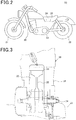
Fig. 2 is a schematic configuration diagram of a motorcycle that is a vehicle in which the alternating current generation system shown inFig. 1 is mounted; -
Fig. 3 is a schematic diagram of an internal configuration of an engine shown inFig. 2 ; -
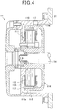
Fig. 4 is a cross-sectional view of an internal configuration of an alternating current generator shown inFig. 3 ; -
Fig. 5 is a schematic diagram of the internal configuration of the alternating current generator shown inFig. 3 ; -
Fig. 6 is a graph for describing an overview of a correction process for rotation phase detection performed by a controller shown inFig. 1 ; -
Fig. 7 is a schematic diagram of a variation example of the internal configuration of the alternating current generator shown inFig. 3 ; -
Fig. 8 is a schematic diagram of another variation example of the internal configuration of the alternating current generator shown inFig. 3 ; -
Fig. 9 is a schematic diagram of another variation example of the internal configuration of the alternating current generator shown inFig. 3 ; -
Fig. 10 is a flowchart for describing an overview of the correction process for rotation phase detection performed by the controller shown inFig. 1 ; -
Fig. 11 is a flowchart for describing an overview of the correction process for rotation phase detection performed by the controller shown inFig. 1 ; -
Fig. 12 is a diagram of an overall circuit configuration of a variation example of the alternating current generation system shown inFig. 1 ; -
Fig. 13 is a diagram of an overall circuit configuration of another variation example of the alternating current generation system shown inFig. 1 ; and -
Fig. 14 is a flowchart for describing an overview of the correction process for rotation phase detection performed by the controller shown inFig. 1 . - An alternating current generation system (or an alternating current generation apparatus) according to an embodiment of the present invention will hereinafter be described with reference to
Fig. 1 to Fig. 6 . - In the specific example according to this embodiment, the number of magnetic poles (2n) is 12 and the number of poles (3m) is 18. However, these quantities can be variously modified. The variation examples are collectively described after the description of the alternating current generation system according to the present embodiment.
- With reference to
Fig. 1 , an alternating current generation system (or an alternating current generation apparatus) 10 according to the present embodiment includes a three-phase alternatingcurrent generator 11. In other words, the alternatingcurrent generator 11 has aU-phase coil 11U, a V-phase coil 11V, and a W-phase coil 11W. Details of the internal configuration of the alternatingcurrent generator 11 will be described hereafter. - The alternating
current generation system 10 also includes abattery 12, acontroller 13, adriver 14, and apower convertor 15. Thepower converter 15 includesswitching elements - The
battery 12 is connected to a load that is provided in a motorcycle 20 (seeFig. 2 ) in which the alternatingcurrent generation system 10 is mounted, so as to supply power to the load. In addition, thebattery 12 is connected to the alternatingcurrent generator 11 with thepower converter 15 therebetween. - The
controller 13 is a so-called microcomputer that includes a central processing unit (CPU), a read-only memory (ROM), a random access memory (RAM), and the like. Thecontroller 13 controls operations of the overall alternatingcurrent generation system 10 by executing routines (programs) that are stored in the ROM in advance. Thedriver 14 is connected to a control terminal (gate or base) of eachswitching element 15U and so on, and is configured to perform so-called "phase control" in thepower converter 15 by outputting drive signals to theswitching elements 15U and so on at appropriate timings under the control of thecontroller 13. In other words, thedriver 14 is capable of performing phase control by controlling the timings of the ON/OFF operations of the switching elements. - The
power convertor 15 is configured to be capable of converting power bi-directionally, between an alternating current and a direct current. Thepower converter 15 is connected to theU-phase coil 11U, the V-phase coil 11V, and the W-phase coil 11W of the alternatingcurrent generator 11 so as to transmit and receive power to and from the alternatingcurrent generator 11. The switchingelements power converter 15 are provided in correspondence to theU-phase coil 11U, the V-phase coil 11V, and the W-phase coil 11W of the alternatingcurrent generator 11. - Specifically, the switching
element 15U and theswitching element 15X are connected in series between the positive terminal and the negative terminal of the battery 12 (the switchingelement 15V and switchingelement 15Y pair and the switchingelement 15W and switchingelement 15Z pair are also similarly connected). The connection position between the switchingelement 15U and theswitching element 15X is connected to one end of theU-phase coil 11U. In a similar manner, the connection position between the switchingelement 15V and theswitching element 15Y is connected to one end of the V-phase coil 11V. In addition, the connection position between the switchingelement 15W and theswitching element 15Z is connected to one end of the W-phase coil 11W. - The switching
element 15U (also similarly applies to theother switching elements 15V and so on) includes a transistor element that is capable of sending a forward-direction current that flows from the positive terminal side to the negative terminal side of thebattery 12 by the control terminal being energized, and a diode element that is capable of sending a reverse-direction current that flows from the negative terminal side to the positive terminal side. Specifically, according to the present embodiment, the switchingelement 15U (also similarly applies to theother switching elements 15V and so on) is composed of an N-channel type metal-oxide-semiconductor field-effect transistor (MOSFET), and a parasitic diode is formed in the direction in which the current flows from the source to the drain. - An electronic control unit (ECU) 16 includes the above-described
controller 13,driver 14, andpower converter 15. In addition, theECU 16 is connected to arotation angle sensor 17. Therotation angle sensor 17 is configured to generate a signal corresponding to the rotation state of the alternating current generator 11 (details of therotation angle sensor 17 will be described hereafter). TheECU 16 is configured to output a control signal for performing phase control of thepower converter 15 to thedriver 14, based on the output from therotation angle sensor 17. In other words, theECU 16 is configured to perform "phase control "of the alternatingcurrent generation system 10 based on the operating state of the motorcycle 20 (seeFig. 2 ). Sections other than therotation angle sensor 17 in the configuration shown inFig. 1 and "phase control" are already known. Therefore, more detailed descriptions thereof are omitted (for example, refer toJP-A-H08-2 14470 JP-A-H10-262343 JP-A-H11-46456 JP-A-2004-173482 - With reference to
Fig. 2 , themotorcycle 20 that corresponds to a vehicle of the present disclosure is provided with afront wheel 21 and arear wheel 22 that serves as a driving wheel. In addition, apower transmission mechanism 23 and avehicle control unit 24 are mounted in themotorcycle 20. Thevehicle control unit 24 is an electronic control unit for controlling the overall operation of themotorcycle 20 and is provided under aseat 25. TheECU 16 shown inFig. 1 is mounted in thevehicle control unit 24. - With reference to
Fig. 3 , asingle cylinder 32 is formed within anengine block 31 that configures the casing of anengine 30. In other words, theengine 30 that is mounted in themotorcycle 20 according to the present embodiment is configured as a so-called "single cylinder engine" that has asingle cylinder 32. Apiston 33 is housed within thecylinder 32 so as to be capable of reciprocal movement along a center axial line of thecylinder 32. Thepiston 33 is connected to a crankshaft 34 with a connectingrod 35 therebetween. - Details of the internal configuration of the alternating
current generator 11 according to the present embodiment will be described below, with reference toFig. 4 andFig. 5 .Fig. 4 corresponds to a cross-sectional view in which the alternatingcurrent generator 11 inFig. 3 is enlarged. According to the present embodiment, ahousing 110 that configures the casing of the alternatingcurrent generator 11 is formed to be substantially cup-shaped from a cross-sectional side view, and is fixed to theengine block 31 so that the opening portion thereof communicates with the inside of theengine block 31. - A
stator 111 is fixed to the inner side of thehousing 110. Thestator 111 is provided with numerous (18 according to the present embodiment)cores 112 that are provided at even intervals along a circumferential direction so as to project outwards in a radiating manner from the rotation center axis of the alternatingcurrent generator 11. A winding 113 that configures theU-phase coil 11U, the V-phase coil 11V, and the W-phase coil 11W is wound around each core. In other words, six each of theU-phase coil 11U, the V-phase coil 11V, and the W-phase coil 11W are arrayed in the order of phases (in the order of U-V-W, that is, theU-phase coil 11U, the V-phase coil 11V, the W-phase coil 11W, theU-phase coil 11U, the V-phase coil 11V, the W-phase coil 11W etc.) and at even intervals along the circumferential direction. - A
rotor 114 is housed within a space surrounded by theengine block 31 and thehousing 110, and is directly connected to thecrank shaft 34. Specifically, therotor 114 includes ayoke 115 that is substantially cup-shaped from a cross-sectional side view. Theyoke 115 is fixed to one end of thecrank shaft 34. An outercircumferential surface 115a of theyoke 115 in the substantially cylindrical portion thereof is provided with numerous detectionsubject portions 116. According to the present embodiment, the detectionsubject portion 116 is a projection provided on the outercircumferential surface 115a and is formed so as to project outwards from the outercircumferential surface 115a. Furthermore, according to the present embodiment, the detectionsubject portions 116 are provided so as to correspond to an array of numerous magnetized portions 117 (reversal state of magnetic poles) that are provided in a fixed manner to the substantially cylindrical portion of theyoke 115. - Specifically, the numerous (12 according to the present embodiment)
magnetized portions 117 are arrayed at even intervals along the circumferential direction so that the orientations of the magnetic poles differ in an alternating manner. With a specific position (the uppermost portion inFig. 5 ) that is the position in which the magnetic poles reverse as a result of two adjacentmagnetized portions 117 abutting each other serving as a base point, a total of 22detection subject portions 116 are provided so as to be continuously arrayed at even intervals (every predetermined interval) in the center positions of themagnetized portions 117 in the circumferential direction and other magnetic pole reversal positions (referred to hereafter as a "commutation positions", including the above-described specific position) where two adjacentmagnetized portions 117 abut each other. The 22 continuous detectionsubject portions 116 form afirst identification portion 118a. - Furthermore, a
second identification portion 118b is formed by an "untoothed" portion (a portion in which two detectionsubject portions 116 are omitted) in which the detectionsubject portions 116 are not provided, between two ends of thefirst identification portion 118a (the two ends in the array direction of the 22 detection subject portions 116). In other words, thesecond identification portion 118b is formed by the exposed outercircumferential surface 115a of theyoke 115 that has a wider width than the width between the adjacent detectionsubject portions 116 in the first identification portion 118. According to the present embodiment, the detectionsubject portion 116 that corresponds to the commutation position is positioned concentrically with the commutation position and is provided so that a straight line drawn from the above-described rotation center axis (that is, the rotation center axis of the rotor 114) towards the commutation position passes through the detection subject portion 116 (however, from electrical and control perspectives, the straight line does not necessarily pass through the center of the detectionsubject portion 116 in the circumferential direction). - In addition, the
rotation angle sensor 17 is mounted in thehousing 110. Therotation angle sensor 17 is disposed opposing the detectionsubject portions 116 so as to generate an output signal that corresponds to the passage state of the detectionsubject portions 116. Specifically, therotation angle sensor 17 is configured to generate a pulse-like signal (referred to, hereafter, as a "passage pulse") each time a detectionsubject portion 116 passes. During a single rotation of the rotor 114 (that is, a single rotation of the crank shaft 34), therotation angle sensor 17 generates an output signal that has a portion in which 22 passage pulses continue in correspondence to the passage of the first identification portion 11a and a portion in which the passage pulse is not present in correspondence to thesecond identification portion 118b. - With reference again to
Fig. 1 , in the alternatingcurrent generation system 10 according to the present embodiment, thecontroller 13 and thedriver 14 in theECU 16 are configured to output, to thepower converter 15, a control signal for performing phase control of the switchingelement 15U and so on that depends on the rotation phase of therotor 114, based on the output from therotation angle sensor 17. In other words, theECU 16 is configured to detect the rotation phase of therotor 114 based on the output from therotation angle sensor 17 and perform phase control based on the detected rotation phase. In addition, theECU 16 is configured to perform correction of the rotation phase (correction of the detection value of the rotation phase) of therotor 114 that has been detected based on the output from therotation angle sensor 17, based on the actual output of the alternatingcurrent generator 11. Details of the correction will be described hereafter. - The operations (working and effects) of the configuration according to the present embodiment will be described below.
- In the configuration according to the present embodiment, the
first identification portion 118a and thesecond identification portion 118b successively pass the position opposing therotation angle sensor 17 in accompaniment with the rotation of therotor 114. At this time, the output signal corresponding to the passage state of the detectionsubject portions 116 is generated by therotation angle sensor 17. - Here, as described above, in the
first identification portion detection subject portions 116 are arrayed at even intervals along the circumferential direction in correspondence to the reversal states (that is, the above-described "commutation positions") of the magnetic poles of the 12magnetized portions 117. Meanwhile, in thesecond identification portion 118b, the detectionsubject portions 116 are not provided. Therefore, the rotation phase of therotor 114 can be accurately detected based on the output signal generated by therotation angle sensor 17. As a result, according to the present embodiment, favorable phase control can be performed even when magnetic sensors for commutation position detection that amount to the number of phases are not provided (typically, even when no magnetic sensor is provided at all). - Here, as described above, the
rotor 114 may be housed in the space surrounded by theengine block 31 and thehousing 110, and directly connected to the crank shaft 34 (in particular, a motorcycle). In this case, the high-temperature lubricating oil within theengine block 31 may fly towards therotor 114 side or therotor 114 may be immersed in the lubricating oil. Therefore, in this case, it is difficult to provide a plurality (that, amounting to the number of phases) of magnetic sensors for commutation position detection. Regarding this point, in the configuration according to the present embodiment, favorable phase control can be performed even in such cases. - Furthermore, the output signal from the
rotation angle sensor 17, such as that described above, can also be used for other purposes (such as detection of engine rotation speed NE that is a signal for operation control like ignition control and fuel injection control in the engine 30). Therefore, in the configuration according to the present embodiment, detection of the rotation phase of therotor 114 and detection of the engine rotation speed (engine rotation frequency) NE for operation control of theengine 30 can be performed by a single detecting means. - A slight error may occur during manufacturing in the correspondence relationship between the position in which the detection
subject portion 116 is provided and the commutation position. In other words, among thedetection subject positions 116, the detectionsubject portions 116 that are formed in correspondence to the commutation positions are each ideally provided so that the generation timing of a zero-crossing point of the phase voltage generated at each winding 113 and a predetermined timing determined by thecontroller 13 based on the passage pulse generated by therotation angle sensor 17 in accompaniment with the passage of the detectionsubject portion 116 are synchronized (both timings match at a control angle "0°CA", described hereafter). In this case, typically, eachmagnetized portion 117 and each detectionsubject portion 116 are formed so that the commutation position and the position of the detectionsubject portion 116 in the circumferential direction substantially match in terms of the mechanical positional relationship (a straight line drawn from the rotation center axis towards the commutation position passes through the vicinity of the center of the detectionsubject portion 116 positioned further outward than the commutation position). As a result, the above-described synchronization can be stably reproduced in manufacturing. - However, an error may occur in the targeted positional relationship, such as that described above, during magnetization (or when magnetized) of the
rotor 114 or formation of the detectionsubject portion 116. Specifically, for example, various errors may occur during machine processing performed to form the detection subject portions 116 (such as an error in the position or shape of a singledetection subject portion 116 or a pitch error among a plurality of detection subject portions 116). Furthermore, an error in phase control may occur as a result of a "delay" occurring in detection and control. - Therefore, according to the present embodiment, the
ECU 16 performs correction of the rotation phase detection (based on the output from the rotation angle sensor 17) of therotor 114 based on the actual output of the alternatingcurrent generator 11. The correction is referred to, hereafter, as simply "phase correction". - Specifically, the power generation output characteristics (output voltage characteristics in relation to engine rotation speed) of when the control angle in phase control (the extent of the advance angle or the delay angle in the energization timing of the switching
element 15U and the like in relation to the output voltage waveform during normal power generation in which phase control is not performed) is "0°CA" in a certain operating state (such as cooling water temperature or outside temperature) in an "ideal" state without any manufacturing errors or control errors is presumed to be as indicated by the solid line inFig. 6 . At this time, should the commutation position be shifted towards the "delay angle" side in relation to the detectionsubject portion 116 as a result of manufacturing error or the like, the power generation output characteristics shift upwards inFig. 6 (see the dotted chain line). Conversely, when the commutation position is shifted towards the "advance angle" side in relation to the detectionsubject portion 116, the power generation output characteristics shift downwards inFig. 6 (see the broken line). - According to the present embodiment, phase correction can be performed by a comparison between the actual output voltage of the alternating
current generator 11 and a predetermined reference value (corresponding to the points on the solid line inFig. 6 ) stored in the ROM or a backup RAM (a non-volatile memory that rewritably stores data and the like during power supply and maintains the storage of data and the like even when power supply is stopped: flash ROM and the like) in advance, at a certain operating point (a certain engine rotation speed inFig. 6 : the "engine rotation speed" herein is acquired based on the output signal from the rotation angle sensor 17). As a result, a more accurate phase control can be performed. The correction value for each operating state is successively stored in the backup RAM in a map-state or a look-up table-state, for each calculation operation. - Several representative variation examples are given below. In the descriptions of the variation examples below, sections having configurations and functions similar to those described in the above-described embodiment are given similar reference numbers as those in the above-described embodiment. Descriptions of such sections can be supported by the descriptions according to the above-described embodiment within a range that technical contradictions do not occur. It goes without saying that the variation examples are not limited to those given below. In addition, the plurality of variation examples can, in their entirety or in part, be used in combination as appropriate within a range that technical contradictions do not occur.
- According to the above-described embodiment, the number of magnetic poles in the
rotor 114, which is the number ofmagnetized portions 117, is 12. The number of poles (the number of cores) in thestator 111 is 18. Thefirst identification portion 118a is the 22 projections that are arrayed at even intervals along the circumferential direction of therotor 114, and thesecond identification portion 118b is the portion that has no projections. However, the present invention is not limited thereto. - In other words, the number of
windings 113, the number ofmagnetized portions 117, and the number of detectionsubject portions 116 can be changed as appropriate. Specifically, the alternatingcurrent generator 11 may be configured so that the number of magnetic poles in therotor 114 is 2n (n is an integer of 1 or greater), and the number of poles in thestator 111 may be 3m (m is an integer of 1 or greater, and may be the same as or differ from n). In addition, the detectionsubject portion 116 is merely required to be provided to include at least the commutation position that is the reversal position of the magnetic poles. As a result of the number of detectionsubject portions 116 being increased, the detection accuracy of the rotation phase of therotor 114 and the engine rotation speed NE is improved, and in particular, the reliability of control against rotation variations is improved. Conversely, as a result of the number of detectionsubject portions 116 not being excessive, the calculation load on thecontroller 13 is reduced. The number of detectionsubject portions 116 omitted in thesecond identification portion 118b can also be changed as appropriate, within a range enabling favorable rotation phase detection. - In the
single cylinder engine 30, because the variation in the reciprocal movement speed of thepiston 33 is significant, it is considered effective to include a large number of detectionsubject portions 116. Anengine 30 having a plurality of cylinders can also be similarly controlled. - In addition, when the position of the detection
subject portion 116 is matched with the commutation position (inter-magnetic pole pitch position), management of the positions of the detectionsubject portions 116 and the assembly positions of the magnets is facilitated, accuracy can be easily improved, and therefore, this configuration is preferable. However, the positions are not necessarily required to match. - From this perspective, as in the specific example given according to the above-described embodiment, when the number of poles in the
stator 111 is 18 and the number of magnetic poles in therotor 114 is 12 (six pole pairs), the number of detectionsubject portions 116 is preferably 22 (24-2). Moreover, as shown inFig. 7 , the detectionsubject portions 116 may only be provided in the commutation positions (the number of detectionsubject portions 116 is 11 = (12-1)). In this case, the passage pulse is generated every 30°CA. Commutation occurs three times between adjacent passage pulses in the U-phase, V-phase, and the W-phase. Therefore, as a result of the wavelength of the passage pulse in the output signal from therotation angle sensor 17 being divided into thirds, estimation of the desired commutation position can be performed with low control load. - The detection
subject portions 116 can be further reduced from the configuration shown inFig. 7 . As a result, further reduction in manufacturing cost and processing load can be achieved. - As shown in
Fig. 8 , two detectionsubject portions 116 may be provided between adjacent commutation positions (the number of detectionsubject portions 116 is 34 = (36-2)). In this case, the array pitch of the detectionsubject portions 116 is also completely synchronous with the array pitch of thewindings 113, in addition to the array of themagnetized portions 117. In other words, the ON/OFF switch timings of the six switchingelements 15U to 15Z and the above-described passage pulse can be completely synchronized so as to be generated at every 10°CA. Therefore, in this configuration, a more accurate phase control becomes possible. - As shown in
Fig. 9 , when the number of poles in thestator 111 is 15 and the number of magnetic poles in therotor 114 is 20 (10 pole pairs), the number of detectionsubject portions 116 is preferably 18 (20-2). - As described above, when expressed using the number of magnetic poles Nj, the number of detection
subject portions 116 Nk can be as indicated below. The number of detectionsubject portions 116 Nk can be selected as appropriate based on the specification of the alternatingcurrent generation system 10 or the high-order system (such as the motorcycle 20) in which the alternatingcurrent generation system 10 is mounted.


- When the alternating
current generation system 10 is mounted in a vehicle and the alternatingcurrent generator 11 is directly connected to thecrank shaft 34 of the engine 30 (in particular, when theengine 30 is a four-cycle engine), rotation variation becomes the largest at the expansion stroke. Therefore, in this case, setting conditions (quantity and positions) of the detectionsubject portions 116 can be set as appropriate so that the robustness of phase control in relation to the rotation variation at the expansion stroke is improved. - The detection
subject portion 116 is not limited to a projection. For example, the detectionsubject portion 116 may be a recessing portion, or may be a portion (such as a black marking) of which the reflectance of electromagnetic waves (typically visible light or infrared light) differs from that of the outercircumferential surface 115a of theyoke 115. - In addition, the
second identification portion 118b may be a portion having a higher presence density of the detectionsubject portions 116 than thefirst identification portion 118a. In other words, when the detectionsubject portions 116 are placed throughout the overall circumference of the outercircumferential surface 115a, thesecond identification portion 118b may be a portion having additional projections for detection of the reference position. - Furthermore, the
second identification portion 118b may be a projection having a larger width in the circumferential direction than the projection included in thefirst identification portion 118a. When the detectionsubject portions 116 are provided evenly on the outercircumferential surface 115a of the yoke 115 (in other words, when thefirst identification portion 118a and thesecond identification portion 118b are not provided: refer toJP-A-2009-232650 engine 30 also being used. - When the output voltage is used for phase correction as in the specific example according to the above-described embodiment, the addition of a detection element for correction is not required. In addition, because the voltage is monitored, minute correction control can be performed that takes into consideration the effects of disturbances. Meanwhile, phase correction can also be performed under principles similar to those of the specific example by using output current as well. In this case, phase correction can be performed while monitoring the current that is the final output performance of the alternating
current generator 11. However, in this case, an element for current detection (such as a shunt resistor or a sense MOS) is required to be provided separately. - In addition, phase correction is preferably performed when the operating state is stable. Therefore, correction may be performed when the values of operating state parameters (such as the engine rotation speed NE, engine cooling water temperature T, and engine load rate KL) or variations therein are predetermined values or lower. This specific example will be described using the flowchart in
Fig. 10 . - The process in
Fig. 10 is performed by thecontroller 13 when a predetermined condition (such as the elapse of a predetermined amount of time t1 after startup of the engine 30) for starting the correction process is met. When the execution of the process is started, first, at Step S1010, thecontroller 13 determines whether or not the variation in engine rotation speed NE is within a predetermined range ΔNE1 (here, the engine rotation speed NE has been obtained based on the output signal from therotation angle sensor 17; the same applies hereafter). When determined that the variation in engine rotation speed NE is within the predetermined range (Step S1010 = YES), the process proceeds to Step S1020, and thecontroller 13 determines whether or not the engine cooling water temperature T is within a predetermined range. When determined that the engine cooling water temperature T is within the predetermined range (Step S1020 = YES), the process proceeds to Step S1030, and thecontroller 13 determines whether or not the deviation between the output voltage V and a target value VR is a predetermined value or higher. Here, the "target value VR" is a reference value in an "ideal" state without any manufacturing errors or control errors, and is stored in the ROM or a backup RAM in advance. - When determined that the variation in engine rotation speed NE is not within the predetermined range (Step S1010 = NO) or the engine cooling water temperature T is not within the predetermined range (Step S1020 = NO), the operating state is not suitable for phase correction in the current process. Therefore, in these cases, the process at Step S1030 and subsequent processes are skipped, and processing of this routine is temporarily ended. Meanwhile, when determined that the deviation between the output voltage V and the target value VR is less than the predetermined value (Step S1030 = NO), correction is not required in the operating state in the current process. Therefore, in this case, the process at Step S1040 and subsequent processes are skipped, and processing of this routine is temporarily ended. Hereafter, the description will be continued under a presumption that the determinations made at Steps S1010 to 1030 are all "YES".
- At Step S1040, under a premise that the deviation between the output voltage V and the target value VR is the predetermined value or higher, the
controller 13 determines whether or not the output voltage V is higher than the target value VR. When determined that the output voltage V is higher than the target value VR (Step S1040 = YES), the process proceeds to Step S1050, and thecontroller 13 advances the control angle by a predetermined minute amount. Meanwhile, when determined that the output voltage V is lower than the target value VR (Step S1040 = NO), the process proceeds to Step S1055, and thecontroller 13 delays the control angle by a predetermined minute amount. - After the process at Step S1050 or 1055 has been performed, the process proceeds to Step S1060. At Step S1060, the
controller 13 determines whether or not the deviation between the output voltage V and the target value VR is less than a predetermined value. When determined that the deviation between the output voltage V and the target value VR is not less than the predetermined value, the determination at Step S1060 becomes "NO" and the process returns to Step S1040. Meanwhile, when determined that deviation between the output voltage V and the target value VR is less than the predetermined value (Step S1060 = YES), the process proceeds to Step S1070, and thecontroller 13 stores the correction value in a map (look-up table) on the backup RAM in correspondence to the operating state (the engine rotation speed NE and the engine cooling temperature T) and a target phase (target control angle). - In addition, phase correction (that is, correction of the rotation phase of the rotor) may be performed based on the variations in actual output from the alternating
current generator 11 when the control angle for phase control is changed, when the operating state is stable. In other words, for example, the correction value obtained as described above can be updated as appropriate by changing (scanning), as appropriate, the control angle for phase control when the operating state is stable. As a result, the reliability of phase correction (in particular, in a high-rotation region in which processing delay occurs) is improved. - Specifically, for example, with reference to the flowchart in
Fig. 11 , when a predetermined correction value update condition (such as the elapse of a predetermined amount of time t2 (>t1) after startup of theengine 30 or the variation amount of the engine rotation speed NE being within a predetermined range ΔNE2 (<ΔNE1)) is met (Step S1110 = YES), thecontroller 13 performs the above-described process in the flowchart inFig. 10 (although the processes at Steps S1010 and S1020 may be omitted), while changing the control angle as appropriate (Step S1120). Subsequently, when this process is performed a predetermined number of times and the correction value map is sufficiently updated, the correction value update process is ended. - Phase correction can also be easily actualized without use of a map by ordinary feedback correction of the target value. Specifically, phase correction can be performed by detecting the peak characteristics (specifically, retrieving the maximum value) of the power generation output (current and/or voltage) when the control angle is changed by a predetermined amount as described above. This technique can be favorably used in the low rotation region in which power generation performance is low. The correction technique may be changed depending on the operating region. Specifically, processing load and correction accuracy can both be achieved by performing the peak-retrieval type feedback correction that does not have a map, such as that described above, for the low rotation region and the update-type correction that uses a map (also referred to as a learning correction), such as that described above, for the intermediate and high rotation regions.
- In addition, as shown in
Fig. 12 , phase correction may also be performed by additionally providing aHall sensor 180 amounting to a single phase as an additional detecting unit that magnetically detects the commutation position. In other words, the effect of "misalignment" between the detectionsubject portion 116 and the commutation position is similar among all of the plurality of phases. Therefore, favorable phase correction can be performed by the phase misalignment being detected in a single arbitrary phase. In this case, the number ofHall sensor 180 elements that is provided is one. Therefore, in this configuration, the accuracy of phase correction can be improved without particularly causing problems in terms of mounting. In this way, providing only asingle Hall sensor 180 to compensate for the misalignment between the detected phase by therotation angle sensor 17 and the actual phase is preferable. - Furthermore, as shown in
Fig. 13 ,Hall sensors rotation angle sensor 17. As a result, even when a situation occurs in which phase control using theHall sensors Hall sensors 180U and so on), a "failsafe" for phase control can be performed through use of therotation angle sensor 17. - Furthermore, in an operating state in which the rotation frequency (rotation speed) of the
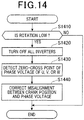
rotor 114 is low, the operations of the transistor elements in all switchingelements 15U to 15Z in thepower converter 15 may be turned OFF, and full-wave rectification may be performed by only the operations of the diode elements. The output voltage waveform of each phase at this time may be monitored, and phase correction may be performed based on the zero-crossing point of the waveform and the output signal from therotation angle sensor 17.Fig. 14 is a flowchart of a specific example of phase correction. - First, at Step S1410, the
controller 13 determines whether or not the current rotation frequency of the rotor 114 (that is, the engine rotation speed NE) is within a predetermined low rotation region. When determined that the rotation frequency of therotor 114 is not within the predetermined low rotation frequency (Step S1410 = NO), the process at Step S1420 and subsequent processes are skipped, and the current correction process is temporarily ended. Meanwhile, when determined that the rotation frequency of therotor 114 is within the predetermined low rotation frequency (Step S1410 = YES), the process proceeds to Step S1420 and subsequent steps, and the correction process is performed. The reason for performing the current correction process in the low rotation region is as follows. In the low rotation region, the amount of power generation is low, and therefore, loss is low and the amount of heat generation caused thereby is low. Therefore, phase detection and correction can be favorably performed. The reversal position of the magnetic poles may be able to be accurately detected without the effects of load current as a result of the generated power becoming low (may often be lower than the battery voltage) and the voltage being a no-load voltage. - At Step S1420, the
controller 13 turns OFF the operations of the transistor elements of all switchingelements 15U to 15Z in the power converter 15 (this is expressed as "turn OFF all inverters" inFig. 14 ). As a result, thepower converter 15 operates as a full-wave rectifier circuit composed of a bridge circuit of six diodes. Then, the process proceeds to Step S1430. - At Step S1430, the
controller 13 monitors the output waveform of the phase voltage generated at least any single phase among theU-phase coil 11U, the V-phase coil 11V, and the W-phase coil 11W, thereby detecting the zero-crossing point of the waveform. Subsequently, the process proceeds to Step S1440. At Step S1440, thecontroller 13 compares the correlation relationship between the generation timing of the zero-crossing point detected at Step S1430 and the output from the rotation angle sensor 17 (the generation timing of the passage pulse) with the correlation relationship in the ideal state such as that described above (theoretical values or demonstrated values of a master product: stored in the ROM or a backup RAM in advance). As a result, correction is performed between the rotation phase detection value based on the output from therotation angle sensor 17 and the actual rotation phase when the control angle is "0°CA". - A more accurate phase control is actualized by the correction shown in
Fig. 14 being performed before the other corrections described above. -
- 10
- alternating current generation system
- 11
- alternating current generator
- 13
- controller
- 14
- driver
- 15
- power converter
- 15U
- switching element
- 15V
- switching element
- 15W
- switching element
- 15X
- switching element
- 15Y
- switching element
- 15Z
- switching element
- 16
- ECU
- 17
- rotation angle sensor
- 111
- stator
- 113
- winding
- 114
- rotor
- 115
- yoke
- 115a
- outer circumferential surface
- 116
- detection subject portion
- 117
- magnetized portion
- 118a
- first identification portion
- 118b
- second identification portion
Claims (10)
- An alternating current generation system (10) comprising:an alternating current generator (11) that includesa rotor (114) having a yoke (115) defining an outer circumferential surface (115a), said rotor (114) has a plurality of magnetized portions (117) arrayed on an inner side of the circumferential surface (115a) along a circumferential direction of the rotor (114), the magnetized portions (117) comprising magnetic poles (S, N), orientation of mutually adjacent two magnetic poles among the magnetic poles (S, N) alternating in the circumferential direction, the mutually adjacent two magnetic poles providing reversal positions of the magnetic poles (S, N) in the circumferential direction, anda stator (111) that has a plurality of windings (113) configuring a plurality of phases and arrayed in order of phases along the circumferential direction,wherein the rotor (114) includes a first identification portion (118a) and a second identification portion (118b) which are formed on the rotor (114), the first identification portion (118a) being formed by a plurality of projections being detected (116) arrayed on an outer side of the circumferential surface (115a) along the circumferential direction in correspondence to reversal states of magnetic poles (S, N) of the plurality of magnetized portions (117), the second identification portion (118b) being formed by providing no projections being detected on the surface of the rotor (114)the projections being detected (116) are provided such that a straight line drawn from a rotation center axis of the rotor (114) towards each of the reversal positions of the magnetic poles (S, N) passes a center of each of the projections being detected (116) in the circumferential direction, andthe projections being detected (116) include a plurality of projections being detected (116) each arrayed along the circumferential direction in correspondence to a corresponding one magnetic pole reversal position in a radial direction of the rotor (114);a power converter (15) that includes a plurality of switching elements (15U to 15Z) capable of being driven ON/OFF, the quantity of which corresponds to the number of phases in the alternating current generator (11), and that bi-directionally converts power between an alternating current and a direct current by driving ON/OFF the plurality of switching elements (15U to 15Z), and is connected to the plurality of windings (113) in the alternating current generator (11) so as to transmit and receive power to and from the alternating current generator (11);a detecting unit (17) that is disposed opposing the rotor (114) so as to generate an output signal corresponding to the passages of the projections being detected (116); anda phase control unit (13, 14) that outputs, to the power converter (15), a control signal to control the phase of the ON/OFF driving of the switching elements based on information on the rotation phase of the rotor (114) based on the output signal from the detecting unit (17), wherein said phase control unit (13, 14) is configured to correct the rotation phase serving as a reference for the phase control by detecting a peak characteristic of the power generation output in the alternating current generator (11) when a control angle for phase control is changed.
- The alternating current generation system (10) according to claim 1, wherein:each of the projections being detected is formed into a tooth-shaped portions protruded from the surface of the rotor (114),the second identification portion (118b) is an untoothed portion formed by excluding the tooth-shaped portions on the surface of the rotor (114).
- The alternating current generation system (10) according to claim 2, wherein:
the untoothed portion has a circumferential length produced by excluding at least one tooth-shaped portion on the surface of the rotor (114). - The alternating current generation system (10) according to claim 3, wherein:
said yoke (115) has a radially outer surface, the tooth-shaped projections being arrayed at intervals on the radially outer surface in the circumferential direction, the untoothed portion being located between both end portions of an array of the tooth-shaped portions in the circumferential direction. - The alternating current generation system (10) according to claim 1, comprising:a further control unit performing a predetermined control process based on the output signal from the detecting unit,the predetermined control process including ignition control or fuel injection control for an internal combustion engine mounted in a vehicle for which the alternating current generation system (10) is configured to be mounted.
- The alternating current generation system (10) according to claim 2, wherein:
the phase control unit (13, 14) is configured to correct the information on the rotation phase serving as reference for phase control based on an actual output of the alternating current generator and a predetermined reference value. - The alternating current generation system according to claims 1 to 6, wherein:
the phase control unit (13, 14) is configured to correct the phase control throughi) said detection of a peak characteristic of an output generated by the alternating current generator, said detection of the peak characteristic does not have a map and is used for a low rotation region, andii) updating a map in which correction values for the phase control are stored, in response to a change in a predetermined amount of control angle for the phase control, said updating the map is used for an intermediate and high rotation regions. - The alternating current generation system (10) according to claim 1, wherein:the phase control unit (13, 14) includes
a rectification operation control means for performing only a full-wave rectification operation with the transistor operations of the switching elements in the power converter (15) turned OFF, in an operating state in which the rotation frequency of the rotor (114) is low,a monitoring means for monitoring an output voltage waveform of at least a single phase among the windings during the full-wave rectification operation, anda correcting means for correcting phase control based on a zero-crossing point of the output voltage waveform and the output signal from the detecting unit. - The alternating current generation system (10) according to any one of claims 1 to 8, wherein:
the detecting unit (17) is configured to be used in ignition control in an internal combustion engine (30). - The alternating current generation system (10) according to any one of claims 1 to 9, further comprising:
a separate hall sensor (180) amounting to a single phase that magnetically detects the reversal positions.
Applications Claiming Priority (2)
| Application Number | Priority Date | Filing Date | Title |
|---|---|---|---|
| JP2012256886A JP6050100B2 (en) | 2012-11-22 | 2012-11-22 | AC power generation system |
| PCT/JP2013/081109 WO2014080882A1 (en) | 2012-11-22 | 2013-11-19 | System for ac power generation in association with power conversion |
Publications (3)
| Publication Number | Publication Date |
|---|---|
| EP2928067A1 EP2928067A1 (en) | 2015-10-07 |
| EP2928067A4 EP2928067A4 (en) | 2016-07-27 |
| EP2928067B1 true EP2928067B1 (en) | 2021-08-25 |
Family
ID=50776064
Family Applications (1)
| Application Number | Title | Priority Date | Filing Date |
|---|---|---|---|
| EP13857496.7A Active EP2928067B1 (en) | 2012-11-22 | 2013-11-19 | System for ac power generation in association with power conversion |
Country Status (4)
| Country | Link |
|---|---|
| US (1) | US9685893B2 (en) |
| EP (1) | EP2928067B1 (en) |
| JP (1) | JP6050100B2 (en) |
| WO (1) | WO2014080882A1 (en) |
Families Citing this family (6)
| Publication number | Priority date | Publication date | Assignee | Title |
|---|---|---|---|---|
| JP6301240B2 (en) * | 2014-02-07 | 2018-03-28 | 本田技研工業株式会社 | Battery charger for vehicle |
| US9966873B2 (en) * | 2014-08-12 | 2018-05-08 | Yiqiang Jake Zhang | Active switching rectifier employing MOSFET and current-based control using a hall-effect switch |
| TWI554018B (en) * | 2015-07-29 | 2016-10-11 | Locomotive intelligent | |
| US11239761B2 (en) * | 2018-01-24 | 2022-02-01 | Infineon Technologies Ag | Coreless current sensor for high current power module |
| US11081948B2 (en) * | 2018-06-28 | 2021-08-03 | Ford Global Technologies, Llc | System and method for in-vehicle resolver alignment |
| JP2022002423A (en) * | 2018-09-26 | 2022-01-06 | 日本電産株式会社 | Motor device |
Citations (1)
| Publication number | Priority date | Publication date | Assignee | Title |
|---|---|---|---|---|
| US20050120782A1 (en) * | 2003-12-08 | 2005-06-09 | Kokusan Denki Co., Ltd. | Engine rotation information detection device |
Family Cites Families (14)
| Publication number | Priority date | Publication date | Assignee | Title |
|---|---|---|---|---|
| JPH06456A (en) | 1992-06-18 | 1994-01-11 | Nippon Steel Corp | Apparatus for carrying work for cleaning apparatus |
| JP3389740B2 (en) | 1994-07-19 | 2003-03-24 | 株式会社デンソー | AC generator |
| US5663631A (en) | 1994-07-19 | 1997-09-02 | Nippondenso Co., Ltd. | Generator with circuitry for controlling power generation based on rotational speed |
| JP3605993B2 (en) | 1997-03-17 | 2004-12-22 | 株式会社デンソー | Power generation equipment for vehicles |
| JP3710602B2 (en) | 1997-07-25 | 2005-10-26 | 国産電機株式会社 | Power generator |
| JPH11355989A (en) | 1998-06-09 | 1999-12-24 | Denso Corp | Flywheel magnet rotor and its manufacture |
| JP2001339889A (en) * | 2000-05-26 | 2001-12-07 | Alps Electric Co Ltd | Spindle motor rotor, index signal outputting device, and fdd device therewith |
| JP4078890B2 (en) * | 2002-06-17 | 2008-04-23 | 国産電機株式会社 | Control device for starter generator for internal combustion engine |
| JP4196637B2 (en) * | 2002-10-17 | 2008-12-17 | 国産電機株式会社 | Internal combustion engine drive power generator |
| JP2004173482A (en) | 2002-11-05 | 2004-06-17 | Kokusan Denki Co Ltd | Power generating device provided with magnet generator |
| JP2006136122A (en) * | 2004-11-05 | 2006-05-25 | Kokusan Denki Co Ltd | Output controller for generator |
| JP2009232650A (en) | 2008-03-25 | 2009-10-08 | Mitsuba Corp | Rotating electrical machine |
| JP5319412B2 (en) * | 2009-06-17 | 2013-10-16 | 本田技研工業株式会社 | Anti-reverse device for motorcycle engine |
| JP5501147B2 (en) * | 2010-08-04 | 2014-05-21 | 新電元工業株式会社 | Phase control device, battery charging device, and phase control method |
-
2012
- 2012-11-22 JP JP2012256886A patent/JP6050100B2/en active Active
-
2013
- 2013-11-19 US US14/646,941 patent/US9685893B2/en active Active
- 2013-11-19 WO PCT/JP2013/081109 patent/WO2014080882A1/en active Application Filing
- 2013-11-19 EP EP13857496.7A patent/EP2928067B1/en active Active
Patent Citations (1)
| Publication number | Priority date | Publication date | Assignee | Title |
|---|---|---|---|---|
| US20050120782A1 (en) * | 2003-12-08 | 2005-06-09 | Kokusan Denki Co., Ltd. | Engine rotation information detection device |
Also Published As
| Publication number | Publication date |
|---|---|
| US9685893B2 (en) | 2017-06-20 |
| EP2928067A4 (en) | 2016-07-27 |
| WO2014080882A1 (en) | 2014-05-30 |
| EP2928067A1 (en) | 2015-10-07 |
| US20150303843A1 (en) | 2015-10-22 |
| JP6050100B2 (en) | 2016-12-21 |
| JP2014107881A (en) | 2014-06-09 |
Similar Documents
| Publication | Publication Date | Title |
|---|---|---|
| EP2928067B1 (en) | System for ac power generation in association with power conversion | |
| US6806687B2 (en) | Vehicle motor-generator apparatus utilizing synchronous machine having field winding | |
| US7081738B2 (en) | Generating device having magneto generator | |
| US9739250B2 (en) | Internal combustion engine ignition device | |
| US20090085418A1 (en) | Generator for vehicle | |
| US8716983B2 (en) | Vehicle-use electric rotating machine | |
| US8564255B2 (en) | Vehicle-use electric rotating machine | |
| CN110401304A (en) | Starter including switched reluctance motor | |
| JP3945696B2 (en) | Rotation detector | |
| JP2010081709A (en) | Field winding type synchronous power generator | |
| KR20060019523A (en) | Method of controlling a polyphase reversible rotating electrical machine for heat-engine motor vehicles | |
| EP3414450B1 (en) | Method and system for controlling an integrated starter-generator | |
| JP7231199B2 (en) | Method and system for crank starting an internal combustion engine | |
| JP2000316298A (en) | Starter generator | |
| JP2018113784A (en) | Control device of power conversion circuit and rotary electric machine unit | |
| CN107743006B (en) | Motor control method, motor control system and running device | |
| JP5709464B2 (en) | Motor drive control device | |
| JP4079421B2 (en) | Rotation detector | |
| JP2001069797A (en) | Current-adjusting device of starter generator | |
| EP3301282A1 (en) | Vehicle | |
| JP6967880B2 (en) | Electronic control device | |
| JP6948845B2 (en) | Electronic control device | |
| JP6948844B2 (en) | Engine starter | |
| WO2018097014A1 (en) | Fault detection device for rotation sensor |
Legal Events
| Date | Code | Title | Description |
|---|---|---|---|
| PUAI | Public reference made under article 153(3) epc to a published international application that has entered the european phase |
Free format text: ORIGINAL CODE: 0009012 |
|
| 17P | Request for examination filed |
Effective date: 20150619 |
|
| AK | Designated contracting states |
Kind code of ref document: A1 Designated state(s): AL AT BE BG CH CY CZ DE DK EE ES FI FR GB GR HR HU IE IS IT LI LT LU LV MC MK MT NL NO PL PT RO RS SE SI SK SM TR |
|
| AX | Request for extension of the european patent |
Extension state: BA ME |
|
| DAX | Request for extension of the european patent (deleted) | ||
| RA4 | Supplementary search report drawn up and despatched (corrected) |
Effective date: 20160629 |
|
| RIC1 | Information provided on ipc code assigned before grant |
Ipc: H02P 6/16 20160101ALI20160623BHEP Ipc: H02P 9/48 20060101ALI20160623BHEP Ipc: H02P 9/04 20060101AFI20160623BHEP Ipc: H02P 6/182 20160101ALI20160623BHEP |
|
| STAA | Information on the status of an ep patent application or granted ep patent |
Free format text: STATUS: EXAMINATION IS IN PROGRESS |
|
| 17Q | First examination report despatched |
Effective date: 20180913 |
|
| STAA | Information on the status of an ep patent application or granted ep patent |
Free format text: STATUS: EXAMINATION IS IN PROGRESS |
|
| GRAP | Despatch of communication of intention to grant a patent |
Free format text: ORIGINAL CODE: EPIDOSNIGR1 |
|
| STAA | Information on the status of an ep patent application or granted ep patent |
Free format text: STATUS: GRANT OF PATENT IS INTENDED |
|
| INTG | Intention to grant announced |
Effective date: 20210312 |
|
| GRAS | Grant fee paid |
Free format text: ORIGINAL CODE: EPIDOSNIGR3 |
|
| GRAA | (expected) grant |
Free format text: ORIGINAL CODE: 0009210 |
|
| STAA | Information on the status of an ep patent application or granted ep patent |
Free format text: STATUS: THE PATENT HAS BEEN GRANTED |
|
| AK | Designated contracting states |
Kind code of ref document: B1 Designated state(s): AL AT BE BG CH CY CZ DE DK EE ES FI FR GB GR HR HU IE IS IT LI LT LU LV MC MK MT NL NO PL PT RO RS SE SI SK SM TR |
|
| REG | Reference to a national code |
Ref country code: GB Ref legal event code: FG4D |
|
| REG | Reference to a national code |
Ref country code: CH Ref legal event code: EP |
|
| REG | Reference to a national code |
Ref country code: DE Ref legal event code: R096 Ref document number: 602013078999 Country of ref document: DE |
|
| REG | Reference to a national code |
Ref country code: IE Ref legal event code: FG4D Ref country code: AT Ref legal event code: REF Ref document number: 1424833 Country of ref document: AT Kind code of ref document: T Effective date: 20210915 |
|
| REG | Reference to a national code |
Ref country code: LT Ref legal event code: MG9D |
|
| RAP4 | Party data changed (patent owner data changed or rights of a patent transferred) |
Owner name: DENSOTRIM CO., LTD. Owner name: DENSO CORPORATION |
|
| RAP4 | Party data changed (patent owner data changed or rights of a patent transferred) |
Owner name: DENSO TRIM CORPORATION Owner name: DENSO CORPORATION |
|
| REG | Reference to a national code |
Ref country code: NL Ref legal event code: MP Effective date: 20210825 |
|
| REG | Reference to a national code |
Ref country code: AT Ref legal event code: MK05 Ref document number: 1424833 Country of ref document: AT Kind code of ref document: T Effective date: 20210825 |
|
| PG25 | Lapsed in a contracting state [announced via postgrant information from national office to epo] |
Ref country code: HR Free format text: LAPSE BECAUSE OF FAILURE TO SUBMIT A TRANSLATION OF THE DESCRIPTION OR TO PAY THE FEE WITHIN THE PRESCRIBED TIME-LIMIT Effective date: 20210825 Ref country code: RS Free format text: LAPSE BECAUSE OF FAILURE TO SUBMIT A TRANSLATION OF THE DESCRIPTION OR TO PAY THE FEE WITHIN THE PRESCRIBED TIME-LIMIT Effective date: 20210825 Ref country code: SE Free format text: LAPSE BECAUSE OF FAILURE TO SUBMIT A TRANSLATION OF THE DESCRIPTION OR TO PAY THE FEE WITHIN THE PRESCRIBED TIME-LIMIT Effective date: 20210825 Ref country code: NO Free format text: LAPSE BECAUSE OF FAILURE TO SUBMIT A TRANSLATION OF THE DESCRIPTION OR TO PAY THE FEE WITHIN THE PRESCRIBED TIME-LIMIT Effective date: 20211125 Ref country code: PT Free format text: LAPSE BECAUSE OF FAILURE TO SUBMIT A TRANSLATION OF THE DESCRIPTION OR TO PAY THE FEE WITHIN THE PRESCRIBED TIME-LIMIT Effective date: 20211227 Ref country code: FI Free format text: LAPSE BECAUSE OF FAILURE TO SUBMIT A TRANSLATION OF THE DESCRIPTION OR TO PAY THE FEE WITHIN THE PRESCRIBED TIME-LIMIT Effective date: 20210825 Ref country code: ES Free format text: LAPSE BECAUSE OF FAILURE TO SUBMIT A TRANSLATION OF THE DESCRIPTION OR TO PAY THE FEE WITHIN THE PRESCRIBED TIME-LIMIT Effective date: 20210825 Ref country code: LT Free format text: LAPSE BECAUSE OF FAILURE TO SUBMIT A TRANSLATION OF THE DESCRIPTION OR TO PAY THE FEE WITHIN THE PRESCRIBED TIME-LIMIT Effective date: 20210825 Ref country code: BG Free format text: LAPSE BECAUSE OF FAILURE TO SUBMIT A TRANSLATION OF THE DESCRIPTION OR TO PAY THE FEE WITHIN THE PRESCRIBED TIME-LIMIT Effective date: 20211125 Ref country code: AT Free format text: LAPSE BECAUSE OF FAILURE TO SUBMIT A TRANSLATION OF THE DESCRIPTION OR TO PAY THE FEE WITHIN THE PRESCRIBED TIME-LIMIT Effective date: 20210825 |
|
| PG25 | Lapsed in a contracting state [announced via postgrant information from national office to epo] |
Ref country code: PL Free format text: LAPSE BECAUSE OF FAILURE TO SUBMIT A TRANSLATION OF THE DESCRIPTION OR TO PAY THE FEE WITHIN THE PRESCRIBED TIME-LIMIT Effective date: 20210825 Ref country code: LV Free format text: LAPSE BECAUSE OF FAILURE TO SUBMIT A TRANSLATION OF THE DESCRIPTION OR TO PAY THE FEE WITHIN THE PRESCRIBED TIME-LIMIT Effective date: 20210825 Ref country code: GR Free format text: LAPSE BECAUSE OF FAILURE TO SUBMIT A TRANSLATION OF THE DESCRIPTION OR TO PAY THE FEE WITHIN THE PRESCRIBED TIME-LIMIT Effective date: 20211126 |
|
| PG25 | Lapsed in a contracting state [announced via postgrant information from national office to epo] |
Ref country code: NL Free format text: LAPSE BECAUSE OF FAILURE TO SUBMIT A TRANSLATION OF THE DESCRIPTION OR TO PAY THE FEE WITHIN THE PRESCRIBED TIME-LIMIT Effective date: 20210825 |
|
| PG25 | Lapsed in a contracting state [announced via postgrant information from national office to epo] |
Ref country code: DK Free format text: LAPSE BECAUSE OF FAILURE TO SUBMIT A TRANSLATION OF THE DESCRIPTION OR TO PAY THE FEE WITHIN THE PRESCRIBED TIME-LIMIT Effective date: 20210825 |
|
| REG | Reference to a national code |
Ref country code: DE Ref legal event code: R097 Ref document number: 602013078999 Country of ref document: DE |
|
| PG25 | Lapsed in a contracting state [announced via postgrant information from national office to epo] |
Ref country code: SM Free format text: LAPSE BECAUSE OF FAILURE TO SUBMIT A TRANSLATION OF THE DESCRIPTION OR TO PAY THE FEE WITHIN THE PRESCRIBED TIME-LIMIT Effective date: 20210825 Ref country code: SK Free format text: LAPSE BECAUSE OF FAILURE TO SUBMIT A TRANSLATION OF THE DESCRIPTION OR TO PAY THE FEE WITHIN THE PRESCRIBED TIME-LIMIT Effective date: 20210825 Ref country code: RO Free format text: LAPSE BECAUSE OF FAILURE TO SUBMIT A TRANSLATION OF THE DESCRIPTION OR TO PAY THE FEE WITHIN THE PRESCRIBED TIME-LIMIT Effective date: 20210825 Ref country code: EE Free format text: LAPSE BECAUSE OF FAILURE TO SUBMIT A TRANSLATION OF THE DESCRIPTION OR TO PAY THE FEE WITHIN THE PRESCRIBED TIME-LIMIT Effective date: 20210825 Ref country code: CZ Free format text: LAPSE BECAUSE OF FAILURE TO SUBMIT A TRANSLATION OF THE DESCRIPTION OR TO PAY THE FEE WITHIN THE PRESCRIBED TIME-LIMIT Effective date: 20210825 Ref country code: AL Free format text: LAPSE BECAUSE OF FAILURE TO SUBMIT A TRANSLATION OF THE DESCRIPTION OR TO PAY THE FEE WITHIN THE PRESCRIBED TIME-LIMIT Effective date: 20210825 |
|
| REG | Reference to a national code |
Ref country code: DE Ref legal event code: R119 Ref document number: 602013078999 Country of ref document: DE |
|
| PG25 | Lapsed in a contracting state [announced via postgrant information from national office to epo] |
Ref country code: MC Free format text: LAPSE BECAUSE OF FAILURE TO SUBMIT A TRANSLATION OF THE DESCRIPTION OR TO PAY THE FEE WITHIN THE PRESCRIBED TIME-LIMIT Effective date: 20210825 |
|
| REG | Reference to a national code |
Ref country code: CH Ref legal event code: PL |
|
| PLBE | No opposition filed within time limit |
Free format text: ORIGINAL CODE: 0009261 |
|
| STAA | Information on the status of an ep patent application or granted ep patent |
Free format text: STATUS: NO OPPOSITION FILED WITHIN TIME LIMIT |
|
| GBPC | Gb: european patent ceased through non-payment of renewal fee |
Effective date: 20211125 |
|
| PG25 | Lapsed in a contracting state [announced via postgrant information from national office to epo] |
Ref country code: LU Free format text: LAPSE BECAUSE OF NON-PAYMENT OF DUE FEES Effective date: 20211119 Ref country code: BE Free format text: LAPSE BECAUSE OF NON-PAYMENT OF DUE FEES Effective date: 20211130 |
|
| REG | Reference to a national code |
Ref country code: BE Ref legal event code: MM Effective date: 20211130 |
|
| 26N | No opposition filed |
Effective date: 20220527 |
|
| PG25 | Lapsed in a contracting state [announced via postgrant information from national office to epo] |
Ref country code: SI Free format text: LAPSE BECAUSE OF FAILURE TO SUBMIT A TRANSLATION OF THE DESCRIPTION OR TO PAY THE FEE WITHIN THE PRESCRIBED TIME-LIMIT Effective date: 20210825 Ref country code: LI Free format text: LAPSE BECAUSE OF NON-PAYMENT OF DUE FEES Effective date: 20211130 Ref country code: CH Free format text: LAPSE BECAUSE OF NON-PAYMENT OF DUE FEES Effective date: 20211130 |
|
| PG25 | Lapsed in a contracting state [announced via postgrant information from national office to epo] |
Ref country code: IE Free format text: LAPSE BECAUSE OF NON-PAYMENT OF DUE FEES Effective date: 20211119 Ref country code: GB Free format text: LAPSE BECAUSE OF NON-PAYMENT OF DUE FEES Effective date: 20211125 Ref country code: DE Free format text: LAPSE BECAUSE OF NON-PAYMENT OF DUE FEES Effective date: 20220601 |
|
| PG25 | Lapsed in a contracting state [announced via postgrant information from national office to epo] |
Ref country code: FR Free format text: LAPSE BECAUSE OF NON-PAYMENT OF DUE FEES Effective date: 20211130 |
|
| PG25 | Lapsed in a contracting state [announced via postgrant information from national office to epo] |
Ref country code: HU Free format text: LAPSE BECAUSE OF FAILURE TO SUBMIT A TRANSLATION OF THE DESCRIPTION OR TO PAY THE FEE WITHIN THE PRESCRIBED TIME-LIMIT; INVALID AB INITIO Effective date: 20131119 |
|
| PG25 | Lapsed in a contracting state [announced via postgrant information from national office to epo] |
Ref country code: CY Free format text: LAPSE BECAUSE OF FAILURE TO SUBMIT A TRANSLATION OF THE DESCRIPTION OR TO PAY THE FEE WITHIN THE PRESCRIBED TIME-LIMIT Effective date: 20210825 |
|
| PGFP | Annual fee paid to national office [announced via postgrant information from national office to epo] |
Ref country code: IT Payment date: 20231124 Year of fee payment: 11 |
|
| PG25 | Lapsed in a contracting state [announced via postgrant information from national office to epo] |
Ref country code: MK Free format text: LAPSE BECAUSE OF FAILURE TO SUBMIT A TRANSLATION OF THE DESCRIPTION OR TO PAY THE FEE WITHIN THE PRESCRIBED TIME-LIMIT Effective date: 20210825 |