JP4196637B2 - Internal combustion engine drive power generator - Google Patents
Internal combustion engine drive power generator Download PDFInfo
- Publication number
- JP4196637B2 JP4196637B2 JP2002303054A JP2002303054A JP4196637B2 JP 4196637 B2 JP4196637 B2 JP 4196637B2 JP 2002303054 A JP2002303054 A JP 2002303054A JP 2002303054 A JP2002303054 A JP 2002303054A JP 4196637 B2 JP4196637 B2 JP 4196637B2
- Authority
- JP
- Japan
- Prior art keywords
- voltage
- phase
- control voltage
- inverter
- rotor
- Prior art date
- Legal status (The legal status is an assumption and is not a legal conclusion. Google has not performed a legal analysis and makes no representation as to the accuracy of the status listed.)
- Expired - Fee Related
Links
Images


Description
【0001】
【発明の属する技術分野】
本発明は、内燃機関により磁石発電機を駆動して負荷を駆動するための電力を得る発電装置に関するものである。
【0002】
【従来の技術】
周知のように、磁石発電機は、回転子ヨークに永久磁石を取り付けることにより磁石界磁を構成した回転子と、回転子の磁石界磁の磁極に対向する磁極部を有する電機子鉄心に電機子コイルを巻装してなる固定子とにより構成される。
【0003】
回転子は原動機の回転軸に取り付けられ、固定子は、原動機のケースやカバーなどに設けられた所定の取り付け部に固定されて、電機子鉄心に設けられた磁極部が回転子の磁極部に所定のギャップを介して対向させられる。
【0004】
磁石発電機においては、回転子の界磁が永久磁石により構成されているため、界磁巻線を有する発電機と同じような方法で界磁を制御して、発電機の出力を制御することはできない。
【0005】
そこで、本出願人は、特許文献1に示されているように、バッテリやコンデンサなどの電圧蓄積手段からインバータを通して電機子コイルに制御電圧を印加することにより、電機子コイルと鎖交する磁束を変化させて、発電機の出力特性を変化させるようにした発電装置を提案した。
【0006】
特許文献1において提案された発電装置は、磁石界磁を有する回転子と磁石界磁の磁極に対向する磁極部を有する電機子鉄心に電機子コイルを巻装してなる固定子とを備えて回転子が内燃機関により駆動される磁石発電機と、この磁石発電機の電機子コイルから得られる交流出力を直流出力に変換してバッテリやコンデンサなどの電圧蓄積手段に供給するAC/DCコンバータとバッテリの電圧を交流制御電圧に変換して電機子コイルに印加するインバータとを備えたAC/DC相互変換部と、電圧蓄積手段からインバータを通して電機子コイルに交流制御電圧を印加するべくインバータを制御するコントローラとを備えていて、バッテリからインバータを通して電機子コイルに印加する交流制御電圧の位相角を変化させることにより磁石発電機の特性を変化させるようにしている。
【0007】
この発電装置においては、現在の電機子コイルの誘起電圧の位相に対して進角した位相角を有する交流制御電圧を電機子コイルに印加することにより発電機の出力を低下させることができ、現在の電機子コイルの誘起電圧の位相に対して遅角した位相角を有する交流制御電圧を電機子コイルに印加することにより発電機の出力を増加させることができる。
【0008】
即ち、電圧蓄積手段からインバータを通して電機子コイルに印加する交流制御電圧の位相を現在の位相よりも進角させるようにインバータを制御すると発電機の出力を低下させることができ、電圧蓄積手段からインバータを通して電機子コイルに印加する交流制御電圧の位相を現在の位相よりも遅角させるようにインバータを制御すると発電機の出力を増大させることができる。
【0009】
従来、磁石発電機の出力電圧を制御する電圧調整器としては、出力電圧が目標値を超えたときに発電機の出力を短絡するようにした短絡式のものが用いられていたが、短絡式の電圧調整器を用いた場合には、電圧調整時に電機子コイルに大きな短絡電流が流れるため、電機子コイルからの発熱が多くなるという問題があった。
【0010】
これに対し、上記のように、電機子コイルに交流制御電圧を印加することができるように構成して、該交流制御電圧の位相を変化させることにより、発電機の出力を調整するようにすれば、短絡電流を流すことなく出力を調整することができるため、電機子コイルの温度が上昇するのを防ぐことができる。
【0011】
特許文献1に示された既提案の発電装置を動作させるためには、インバータから交流制御電圧を出力させるタイミングを定めるために、回転子の磁石界磁の回転角度位置を検出する位置センサを設ける必要がある。特許文献1には、同じように磁石界磁の回転角度位置を検出してインバータを制御するタイミングを制御する必要があるブラシレス直流電動機の例にならって、上記位置センサとしてホール素子を用いることが開示されている。
【0012】
【特許文献1】
特開平11−46456号公報
【0013】
【発明が解決しようとする課題】
磁石発電機を内燃機関により駆動する場合に上記既提案の発明を適用しようとすると下記のような問題が生じることが明らかになった。
【0014】
即ち、内燃機関に磁石発電機を取り付ける場合には、通常発電機が機関のカバー内に配置されるため、該発電機の温度は150℃を超えることがある。この場合、磁石界磁の回転角度位置を検出するセンサも同じ温度に曝されることになるが、ホール素子は半導体素子であるため、150℃もの高温下では使用することはできない。
【0015】
従って、磁石発電機を駆動する原動機として内燃機関を用いる発電装置に特許文献1に記載された発明を適用するためには、ホール素子を用いずに交流制御電圧を発生させるタイミングを定めることができるようにするか、または発電機を機関のカバーの外に配置してその冷却を良好にするように機関を設計し直す必要がある。
【0016】
本発明の目的は、内燃機関により駆動される磁石発電機の電機子コイルにバッテリからインバータを通して所定の位相角を有する交流制御電圧を印加することにより発電機の出力調整を行うようにした発電装置において、半導体素子からなるセンサを用いることなく、交流制御電圧を発生させるタイミングを定めることができるようにすることにある。
【0017】
【課題を解決するための手段】
本発明は、2n極(nは1以上の整数)の磁石界磁を有する回転子と磁石界磁の磁極に対向する磁極部を有する電機子鉄心にm相(mは1以上の整数)の電機子コイルを巻装してなる固定子とを備えて回転子が内燃機関により駆動される磁石発電機と、磁石発電機のm相の電機子コイルから得られる交流出力を直流出力に変換して電圧蓄積手段に供給するAC/DCコンバータと電圧蓄積手段の両端の電圧をm相の交流電圧に変換して電機子コイルに印加するインバータとを備えたAC/DC相互変換部と、発電機の特性を調整するために電圧蓄積手段からインバータを通して電機子コイルに交流制御電圧を印加するべくインバータを制御するコントローラとを備えた内燃機関駆動発電装置を対象とする。
【0018】
本発明においては、回転子の回転角度位置が予め定められた特定の回転角度位置に一致する毎に磁束の変化をコイルにより検出してパルスを発生する磁束変化検出形の信号発生装置を設ける。
【0019】
またコントローラは、信号発生装置が発生するパルスの発生間隔に基づいて磁石発電機の回転速度情報を得る回転速度検出手段と、電圧蓄積手段の両端の電圧を設定電圧と比較して、電圧蓄積手段の両端の電圧が設定電圧よりも低いときには交流制御電圧の位相を現在の位相よりも遅らせるように前記交流制御電圧の位相角を決定し、電圧蓄積手段の両端の電圧が設定電圧よりも高いときには前記交流制御電圧の位相を現在の位相よりも進ませるように該交流制御電圧の位相角を決定する制御電圧位相角決定手段と、制御電圧位相角決定手段により決定された位相角を有する交流制御電圧の各零点を目標零点として該目標零点と前記信号発生装置が特定のパルスを発生する回転角度位置との間の角度差を演算し、演算した角度差を、回転速度検出手段により得られた磁石発電機の回転速度情報を用いて特定のパルスが発生する回転角度位置から目標零点まで回転子が回転するのに要する時間を示す時間データに変換し、信号発生装置が特定のパルスを発生した時に時間データの計測を開始して該時間データの計測が完了したときの回転子の回転角度位置を電機子コイルに印加すべき交流制御電圧の零点として推測する制御電圧零点推測手段と、この制御電圧零点推測手段により推測された各零点に各零点が一致する交流電圧を前記電圧蓄積手段から前記インバータを通して前記電機子コイルに印加するようにインバータを制御するインバータ制御手段とを備えた構成とする。
【0020】
磁束変化検出形の信号発生装置としては、例えば、リラクタを有するロータと、該ロータのリラクタの回転方向の前端側エッジ及び後端側エッジをそれぞれ検出したときにパルスを発生するパルサとにより構成される誘導子形の信号発生装置を用いることができる。
【0021】
パルサは、リラクタに対向する磁極部を有する鉄心と該鉄心に巻回された信号コイルと、該鉄心に磁気結合された永久磁石とを備えていて、リラクタの回転方向の前端側エッジがパルサの鉄心の磁極部の位置を通過する際、及びリラクタの回転方向の後端側エッジがパルサの鉄心の磁極部の位置を通過する際にそれぞれ鉄心中で生じる磁束の変化により、信号コイルにパルス信号を誘起させる。
【0022】
このように、磁束変化をコイルにより検出してパルスを発生する磁束変化検出形の信号発生装置は、半導体素子を用いずにパルス信号を発生するように構成されるため、該信号発生装置を発電機とともに機関のカバー内に配置しても何ら支障を来さない。
【0023】
上記信号発生装置は、磁石界磁の磁極構成に対して一定の関係を有する位置で生じさせられる磁束の変化を検出してパルスを出力するため、このパルスの発生位置は、発電機の電機子コイルに誘起する交流電圧の位相と一定の関係を有しており、電圧蓄積手段からインバータを通して電機子コイルに印加すべき交流制御電圧の各零点も、信号発生装置の出力パルスに対して一定の関係を有している。
【0024】
従って、上記のような信号発生装置を設けておくと、交流制御電圧の各零点のタイミングを目標零点として、信号発生装置がパルスを出力するタイミングと発電機の回転速度の情報を含む変量の計測値とから各目標零点を推測することができ、推測した各目標零点に各零点が一致した交流電圧を発生させるようにインバータを制御することにより、所望の位相角を有する交流制御電圧を電機子コイルに印加することができる。
【0025】
例えば、発電機の特性を所望の特性とするために必要な交流制御電圧の位相を、信号発生装置がパルスを発生する位置から該交流制御電圧の発生位置(最初の零点)までの角度として求めて、この角度を現在の発電機の回転速度を用いて時間データに変換すると、信号発生装置がパルスを発生するタイミングから交流制御電圧を発生させるタイミングまでの時間を求めることができるので、この時間を第1の予測経過時間として、信号発生装置がパルスを発生したときにこの予測経過時間をタイマにより計測することにより、交流制御電圧を発生させるタイミング(最初の零点)を推測することができる。
【0026】
発電機の回転速度は、例えば、信号発生装置が特定の信号を発生する周期(例えば発電機が1回転するのに要する時間)から求めることができる。
【0027】
また交流制御電圧の2番目以降の各零点は、1つ前の零点でタイマをスタートさせて、該タイマに電気角で180°/m(3相発電機の場合には60°)に相当する時間を計測させることにより推測することができる。
【0028】
インバータとしては、ブリッジの各辺にスイッチ素子を有してオン状態にするスイッチ素子の組み合わせを切り換えることによりバッテリの電圧をm相の交流電圧に変換するブリッジ形インバータを用いることができる。
【0029】
この場合も、コントローラには、信号発生装置が発生するパルスの発生間隔に基づいて磁石発電機の回転速度情報を得る回転速度検出手段と、電圧蓄積手段の両端の電圧を設定電圧と比較して、電圧蓄積手段の両端の電圧が設定電圧よりも低いときには交流制御電圧の位相を現在の位相よりも遅らせるように前記交流制御電圧の位相角を決定し、電圧蓄積手段の両端の電圧が設定電圧よりも高いときには前記交流制御電圧の位相を現在の位相よりも進ませるように該交流制御電圧の位相角を決定する制御電圧位相角決定手段と、制御電圧位相角決定手段により決定された位相角を有する交流制御電圧の各零点を目標零点として該目標零点と前記信号発生装置が特定のパルスを発生する回転角度位置との間の角度差を演算し、演算した角度差を、回転速度検出手段により得られた磁石発電機の回転速度情報を用いて特定のパルスが発生する回転角度位置から目標零点まで回転子が回転するのに要する時間を示す時間データに変換し、信号発生装置が特定のパルスを発生した時に時間データの計測を開始して該時間データの計測が完了したときの回転子の回転角度位置を電機子コイルに印加すべき交流制御電圧の零点として推測する制御電圧零点推測手段と、この制御電圧零点推測手段により推測された各零点に各零点が一致する交流電圧を前記電圧蓄積手段から前記インバータを通して前記電機子コイルに印加するようにインバータを制御するインバータ制御手段とを備えた構成とする。
【0030】
またインバータ制御手段は、制御電圧零点推測手段により推測された各目標零点で交流制御電圧をインバータから出力させるためにインバータのいずれのスイッチ素子をオン状態とし、いずれのスイッチ素子をオフ状態とするかを示すオンオフパターンを発生させるオンオフパターン発生手段と、オンオフパターン発生手段が発生するオンオフパターンに従ってインバータのオン状態にすべきスイッチ素子に駆動信号を与えるインバータ駆動部とを備えた構成とするのが好ましい。
【0031】
本発明の好ましい態様では、上記信号発生装置が、360°/2nの極弧角を有するリラクタを等角度間隔でn個有して前記回転子と共に回転させられる信号発生用ロータと、前記信号発生用ロータの各リラクタの回転方向の前端側エッジ及び後端側エッジをそれぞれ検出してパルスを発生する1つのパルサとにより構成される。この場合、コントローラは、信号発生装置のパルサが発生するパルスの発生間隔に基づいて前記磁石発電機の回転 速度情報を得る回転速度検出手段と、電圧蓄積手段の両端の電圧を設定電圧と比較して、電圧蓄積手段の両端の電圧が設定電圧よりも低いときには各相の交流制御電圧の位相を現在の位相よりも遅らせるように各相の交流制御電圧の位相角を決定し、電圧蓄積手段の両端の電圧が設定電圧よりも高いときには各相の交流制御電圧の位相を現在の位相よりも進ませるように各相の交流制御電圧の位相角を決定する制御電圧位相角決定手段と、制御電圧位相角決定手段により決定された位相角を有する各相の交流制御電圧の各零点を目標零点として該目標零点と前記パルサが特定のパルスを発生する回転角度位置との間の角度差を演算し、演算した角度差を、前記回転速度検出手段により得られた磁石発電機の回転速度情報を用いて特定のパルスが発生する回転角度位置から目標零点まで回転子が回転するのに要する時間を示す時間データに変換し、パルサが特定のパルスを発生した時に時間データの計測を開始して該時間データの計測が完了したときの回転子の回転角度位置を電機子コイルに印加すべき各相の交流制御電圧の零点として推測する制御電圧零点推測手段と、制御電圧位相角決定手段により位相角が決定された各相の交流制御電圧をインバータから出力させるために、制御電圧零点推測手段により推測された各相の交流制御電圧の各零点でインバータのいずれのスイッチ素子をオン状態とし、いずれのスイッチ素子をオフ状態とするかを示すオンオフパターンを発生させるオンオフパターン発生手段と、オンオフパターン発生手段が発生するオンオフパターンに従ってインバータのオン状態にすべきスイッチ素子に駆動信号を与えるインバータ駆動部とを備えた構成とする。
【0032】
また本発明の他の好ましい態様では、磁石発電機にm相(mは2以上の整数)の電機子コイルが設けられる場合に、信号発生装置が、360°/2nの極弧角を有するリラクタを等角度間隔でn個有して前記回転子と共に回転させられる信号発生用ロータと、前記m相の電機子コイルに対してそれぞれ設けられて前記信号発生用ロータの周方向に等間隔で配置されたm個のパルサとを備えて、各相のパルサがロータの一連のリラクタの回転方向の前端側エッジ及び後端側エッジをそれぞれ検出してパルスを発生するように構成される。
【0033】
この場合、コントローラは、信号発生装置が発生するパルスの発生間隔に基づいて磁石発電機の回転速度情報を得る回転速度検出手段と、電圧蓄積手段の両端の電圧を設定電圧と比較して、電圧蓄積手段の両端の電圧が設定電圧よりも低いときには各相の交流制御電圧の位相を現在の位相よりも遅らせるように各相の交流制御電圧の位相角を決定し、電圧蓄積手段の両端の電圧が設定電圧よりも高いときには各相の交流制御電圧の位相を現在の位相よりも進ませるように該交流制御電圧の位相角を決定する制御電圧位相角決定手段と、制御電圧位相角決定手段により決定された位相角を有する各相の交流制御電圧の各零点を目標零点として該目標零点と前記パルサが特定のパルスを発生する回転角度位置との間の角度差を演算し、演算した角度差を、回転速度検出手段により得られた磁石発電機の回転速度情報を用いてパルサが特定のパルスを発生する回転角度位置から目標零点まで回転子が回転するのに要する時間を示す時間データに変換し、各相のパルサが特定のパルスを発生した時に時間データの計測を開始して該時間データの計測が完了したときの回転子の回転角度位置を電機子コイルに印加すべき各相の交流制御電圧の零点として推測する制御電圧零点推測手段と、制御電圧位相角決定手段により位相角が決定された各相の交流制御電圧を前記インバータから出力させるために、制御電圧零点推測手段により推測された各相の交流制御電圧の各零点で前記インバータのいずれのスイッチ素子をオン状態とし、いずれのスイッチ素子をオフ状態とするかを示すオンオフパターンを発生させるオンオフパターン発生手段と、オンオフパターン発生手段が発生するオンオフパターンに従ってインバータのオン状態にすべきスイッチ素子に駆動信号を与えるインバータ駆動部とを備えた構成とする。
【0034】
上記磁石発電機の回転子としては、強磁性材料によりほぼカップ状を呈するように形成された回転子ヨークの周壁部の内周に永久磁石を取り付けて前記磁石界磁を構成したものを用いることができる。この場合、回転子ヨークの周壁部の外周にリラクタが設けられて、該リラクタと回転子ヨークとにより信号発生用ロータが構成される。
【0035】
また上記磁石発電機の回転子として、固定子の内側で回転する内転形のものを用いることができる。この場合、回転子とは別個に設けられた回転体を発電機の回転軸に取り付けて、該回転体に前記リラクタを設けることにより、信号発生用ロータを構成することができる。
【0036】
本発明の好ましい態様では、上記リラクタの少なくとも一部が、内燃機関の点火時期を検出する際の基準となる信号を発生させるために用いられる点火用のリラクタを兼ねるように設けられる。そのためには、例えば、n個のリラクタの内の1つのリラクタを、回転子ヨーク(または回転体)の外周面からの高さが高い第1の部分と該第1の部分よりも回転子ヨーク(または回転体)の外周面からの高さが低い第2の部分とを有する2段リラクタとして、該1つのリラクタの全体の極弧角と他のリラクタのそれぞれの極弧角とを等しく設定し、パルサが1つのリラクタの回転方向の前端側エッジを検出したときに発生するパルスを、パルサが他のリラクタの回転方向の前端側のエッジを検出したときに発生するパルスとともに、交流制御電圧の零点を求めるために用いる。またパルサが1つのリラクタの第1の部分と第2の部分との境界部分に形成されたエッジを検出したときに発生するパルスを、内燃機関の点火時期を求める際の基準位置を検出するためのパルスとして用いる。
【0037】
本発明の好ましい態様では、磁石発電機の特性を調整するためにインバータから出力される電流を所定のデューティ比で断続させるようにインバータを制御するPWM制御手段が更に設けられる。
【0038】
このようにPWM制御手段を設けると、交流制御電圧の位相を適当な位相に固定しておいて、インバータの出力をPWM制御することにより、発電機の特性をきめ細かく制御することができる。
【0039】
制御電圧零点推測手段は、回転子の回転速度が反映された時間の計測値を用いて各目標零点を特定する角度データを時間データに変換する時間データ変換手段手段と、時間データを計測して該時間データの計測を完了したときのタイミングを各目標零点として推測する計時手段とを備えた構成とすることができる。
【0040】
【発明の実施の形態】
以下図面を参照して本発明の実施の形態を説明する。
【0041】
図1は、固定子に3相の電機子コイルを有する磁石発電機を用いる場合に本発明を適用した第1の実施形態の全体的な構成を示したもので、同図において1は内燃機関により駆動される磁石発電機、2はバッテリ、3は磁石発電機1とバッテリ2との間に設けられたAC/DC相互変換部、4はマイクロプロセッサを備えて、AC/DC相互変換部3に設けられるインバータを制御するコントローラ、5は磁石発電機1の回転子の回転角度位置が予め定めた位置に一致したときにパルスを発生する信号発生装置である。
【0042】
更に詳細に説明すると、図1において、10は鉄などの強磁性材料によりほぼカップ状を呈するように構成された回転子ヨークで、この回転子ヨークは、その底壁部の中央部に取り付けられたボス部が内燃機関(図1には図示せず。)のクランク軸に嵌着されて機関に取り付けられている。
【0043】
この種の磁石発電機においては、回転子ヨーク10の周壁部10aの内周に永久磁石が取り付けられて2n極(nは1以上の整数)の磁石界磁が構成される。本発明の第1の実施形態では、図1に示すように、回転子ヨーク10の周壁部10aの内周に180°間隔で配置された2個の円弧状の永久磁石M1及びM2が接着により取り付けられていて、これらの磁石が着磁方向を異にして径方向に着磁されることにより、回転子ヨークの内周に2極の磁石界磁が構成されている。回転子ヨーク10と永久磁石M1及びM2とにより磁石発電機の回転子1Aが構成されている。回転子1Aは、機関の正回転時に図1において時計方向に回転させられる。
【0044】
回転子1Aの内側には、固定子1Bが配置されている。この固定子は、環状に形成された継鉄部Yの外周部から3個の突極部P1ないしP3を放射状に突出させた構造を有する星形環状の電機子鉄心15と、電機子鉄心の突極部P1及びP2にそれぞれ巻回された3相の電機子コイルLuないしLwとからなっている。図示の例では、突極部P1ないしP3にそれぞれ巻回された3相の電機子コイルLuないしLwが星形結線されて、これらの電機子コイルの中性点と反対側の端末部から3相の出力端子1u,1v及び1wが引き出されている。
【0045】
固定子1Bは、内燃機関のケースの一部に形成された固定子取り付け部に固定されて、電機子鉄心15の突極部P1ないしP3のそれぞれの先端に形成された磁極部が回転子1Aの磁石界磁の磁極に所定のギャップを介して対向させられている。
【0046】
回転子ヨーク10の周壁部10aの外周には、該周壁部の周方向に延びる円弧状の突起からなる1つのリラクタ17が形成され、このリラクタ17と回転子ヨーク10とにより信号発生用ロータ5Aが構成されている。
【0047】
信号発生用ロータ5Aの側方には、パルサ5Bが配置され、ロータ5Aとパルサ5Bとにより信号発生装置5が構成されている。パルサ5Bはリラクタ17に対向する磁極部を先端に有する鉄心と、該鉄心に巻回された信号コイルと、該鉄心に磁気結合された永久磁石とを備えた周知のもので、機関のケースに固定されて、その磁極部が回転子ヨークのリラクタ17が設けられた領域に対向させられている。
【0048】
パルサ5Bは、リラクタ17の回転方向の前端側のエッジ17aが該パルサ5Bの磁極部との対向を開始する際、及びリラクタ17の回転方向の後端側エッジ17bがパルサ5Bの磁極部との対向を終了する際にそれぞれ鉄心中で生じる磁束の変化により、信号コイルから極性が異なるパルスを発生させる。パルサ5Bから得られるパルス信号は、内燃機関を点火する点火装置に機関の回転情報を与えるための信号として用いられる外、磁石発電機の回転子の磁石界磁の回転角度位置を検出する位置検出信号として用いられる。
【0049】
図3(A)に示すように、本実施形態では、発電機の回転子の回転角度位置(機関のクランク軸の回転角度位置)θが予め設定された第1の位置θs1に一致したときにパルサ5Bがしきい値以上の正極性の第1のパルスVs1を発生し、回転角度位置θが機関の低速時の点火位置として用いられる第2の位置θs2に一致したときにしきい値以上の負極性の第2のパルスVs2を発生するようにリラクタ17とパルサ5Bとが設けられている。パルサ5Bが第1のパルスVs1を発生する位置θs1は、機関の点火位置(機関の点火が行われるときのクランク軸の回転角度位置)の最大進角位置よりも進角した位置に設定され、第2の位置θs2は機関の上死点に近い位置に設定されている。なお図示の例では機関が単気筒であるとしている。
【0050】
図示の例では、リラクタ17の回転方向の前端側のエッジが磁石界磁のN極とS極との間の中心位置(磁極間中心位置)θmoに対して電気角でα°ずれた位置にあり、パルサ5Bの中心が、発電機のU相の交流誘起電圧に対する交流制御電圧の進角度が0度になる基準位置θou(この例では、U相の電機子コイルLuの交流誘起電圧の正の半波が立ち上がる直前の零点が生じる位置)に対して電気角でβ°ずれた位置に配置されている。
【0051】
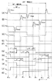
AC/DC相互変換部3は、ダイオードDu,Dv,Dw,Dx,Dy及びDzをブリッジ接続して構成したダイオードブリッジ全波整流回路からなるAC/DCコンバータと、MOSFETからなるスイッチ素子Qu,Qv,Qw,Qx,Qy及びQzをブリッジ接続して構成したブリッジ形スイッチ回路と、このスイッチ回路の直流側端子の両端に接続されたコンデンサCaとからなるブリッジ形インバータとからなっている。図示の例では、インバータを構成するスイッチ素子Qu,Qv,Qw,Qx,Qy及びQzがそれぞれ整流回路を構成するダイオードDu,Dv,Dw,Dx,Dy及びDzに逆並列接続されていて、コンバータ及びインバータの3相の交流側端子につながる交流側外部端子3u,3v及び3wがそれぞれ発電機1の3相の出力端子1u,1v及び1wに接続され、コンバータ及びインバータの直流側端子につながる正極側及び負極側の直流側外部端子3a及び3bがバッテリ2の正極端子及び負極端子にそれぞれ接続されている。
【0052】
ダイオードDu,Dv,Dw,Dx,Dy及びDzにより構成された全波整流回路からなるAC/DCコンバータは、電機子コイルLuないしLwに誘起する3相交流電圧を整流してバッテリ2に充電電流を供給する。
【0053】
またスイッチ素子Qu,Qv,Qw,Qx,Qy及びQzのブリッジ回路からなるインバータは、発電機の出力を調整する必要があるときにバッテリ2の電圧を交流電圧に変換して、該交流電圧を交流制御電圧として電機子コイルLuないしLwに印加する。
【0054】
コントローラ4はマイクロプロセッサを備えていて、該マイクロプロセッサには、信号発生装置5のパルサ5Bから得られる信号が波形整形回路18を通して入力されるとともに、バッテリ2の両端の電圧を検出する電圧検出回路19の出力が入力されている。
【0055】
波形整形回路18は、例えば、パルサ5Bが出力するパルスVs1及びVs2によりセット及びリセットされるフリップフロップ回路からなっていて、図3(B)に示すように、第1のパルスVs1の発生位置で立上り、第2のパルスVs2の発生位置で立ち下がる矩形波状のパルサ信号Pを出力する。コントローラ4に設けられているマイクロプロセッサは、このパルサ信号Pの立上り及び立下りをそれぞれ認識したときに第1のパルスVs1及び第2のパルスVs2が発生したことを検出する。
【0056】
コントローラ4のマイクロプロセッサは、パルサ5Bが出力するパルスが有する回転角度位置情報と、電圧検出回路19から与えられるバッテリの電圧情報とを入力として、電機子コイルLuないしLwに誘起する交流誘起電圧に対して所定の位相角を有する交流制御電圧をバッテリ2からAC/DC相互変換部3のインバータを通して電機子コイルLuないしLwに印加するように、インバータを制御する。バッテリ2からAC/DC相互変換部のインバータを通して電機子コイルに印加する交流制御電圧の位相角は、バッテリ2の両端の電圧を設定電圧に保つために、進み側から遅れ側まで変化させられる。
【0057】
前記特許文献1に詳細に説明されているように、磁石発電機においては、バッテリからインバータを通して電機子コイルに交流制御電圧を印加するようにすると、該交流制御電圧の位相角を変化させることにより、電機子コイルに鎖交する磁束の量を変化させて発電機の出力を変化させることができる。即ち、交流制御電圧の位相角を現在の位相角に対して相対的に進角側に変化させると電機子コイルに鎖交する磁束の量を減少させて発電機の出力を低下させることができ、交流制御電圧の位相角を現在の位相角に対して相対的に遅角側に変化させると電機子コイルに鎖交する磁束の量を増加させて発電機の出力を増加させることができる。
【0058】
従って、図1に示したように、磁石発電機の出力でバッテリ2を充電する場合、内燃機関の回転速度が上昇してバッテリ2の両端に印加される電圧が設定電圧よりも上昇したときには、交流制御電圧の位相を現在の位相よりも進み側に変化させることにより発電機の出力を低下させてバッテリの両端の電圧を設定電圧に戻すことができ、また機関の回転速度が低下してバッテリの両端に印加される電圧が設定電圧よりも低くなったときには、交流制御電圧の位相を現在の位相よりも遅れ側に変化させることにより発電機の出力を増大させて、バッテリの両端の電圧を設定電圧に戻すことができる。
【0059】
図示のように発電機が3相の電機子コイルを有している場合、3相の交流誘起電圧には、該交流誘起電圧に電気角で60°毎に順次零点が現れ、電気角で360°の区間に合計6個の零点が現れる。
【0060】
この場合、本発明では、オン状態にするインバータのスイッチ素子の組み合わせを電気角で60°毎に切り換えることにより、インバータ3Bから電機子コイルLu〜Lwに3相交流制御電圧を印加する。
【0061】
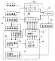
コントローラ4は、マイクロプロセッサに所定のプログラムを実行させることによりインバータを制御するための各種の機能実現手段を構成する。本実施形態においてコントローラ4により構成される機能実現手段を図2に示した。図2においては、AC/DC相互変換部3を構成するAC/DCコンバータ3Aと、インバータ3Bとが分けて図示されている。
【0062】
コンバータ3Aはダイオードブリッジ全波整流回路からなっていて、磁石発電機1の電機子コイルに誘起する交流電圧を直流電圧に変換して電圧蓄積手段としてのバッテリ2に供給する。またインバータ3Bは、スイッチ素子Qu〜Qw及びQx〜Qzのブリッジ回路からなっていて、バッテリ2の電圧を電機子コイルLuないしLwに誘起する交流誘起電圧に対して所定の位相角を有する交流制御電圧に変換して電機子コイルLuないしLwに印加する。
【0063】
コントローラ4に設けられたマイクロプロセッサは、所定のプログラムを実行することにより、回転速度検出手段20と、制御電圧位相角決定手段21と、制御電圧零点推測手段22と、オンオフパターン発生手段23とを実現する。コントローラはまた、オンオフパターン発生手段23が発生するオンオフパターンに従ってインバータ3Bに駆動信号を与えるインバータ駆動部24をハードウェア回路として備えている。
【0064】
回転速度検出手段20は、発電機の回転速度の情報を得る手段で、この回転速度検出手段は、信号発生装置5がパルスVs1を発生する間隔(回転子が1回転するのに要する時間)や、パルスVs1及びパルスVs2の発生間隔(回転子がリラクタの極弧角に等しい角度回転するのに要する時間)など、発電機の回転速度が反映された時間を計測する手段により構成される。
【0065】
制御電圧位相角決定手段21は、バッテリの両端の電圧を設定電圧に近づけるために必要な交流制御電圧の位相角を決定する手段で、電圧検出回路19により検出されたバッテリ2の両端の電圧を設定電圧と比較して、バッテリの両端の電圧が設定電圧よりも低いときには、交流制御電圧の位相を、現在の位相よりも遅らせるように該交流制御電圧の位相角を決定し、バッテリの両端の電圧が設定電圧よりも高いときには、交流制御電圧の位相を現在の位相よりも進ませるように該交流制御電圧の位相角を決定する。
【0066】
制御電圧零点推測手段22は、制御電圧位相角決定手段21により決定された位相角を有する交流制御電圧の各零点を目標零点として、該目標零点を、信号発生装置5が特定のパルスを発生するタイミングを基にして推測する。
【0067】
この制御電圧零点推測手段は、例えば、信号発生装置が特定のパルスを発生する位置から、電機子コイルに印加しようとする交流制御電圧の最初の目標零点(交流制御電圧を発生させるタイミング)までの角度を第1の零点計測用角度として演算する第1の零点計測用角度演算手段と、演算された第1の零点計測用角度を発電機の回転速度を用いて時間データ(その角度を発電機の回転軸が回転するのに要する時間)に変換する演算を行って信号発生装置が特定のパルスを発生するタイミングから交流制御電圧の最初の目標零点までの予測経過時間を第1の予測経過時間として求める第1の予測経過時間演算手段と、2番目以降の零点相互間の角度である第2の零点計測用角度180°/m(3相交流制御電圧を発生させる場合は60°)を回転速度を用いて時間データに変換して零点相互間の予測経過時間を第2の予測経過時間として演算する第2の予測経過時間演算手段と、信号発生装置が特定のパルスを発生する毎に上記第1の予測経過時間をタイマに計測させて、該第1の予測経過時間の計測が完了するタイミングを最初の目標零点として推測する第1の計時手段と、最初の目標零点及び2番目以降の各目標零点が推測される毎に上記第2の予測経過時間をタイマに計測させてその計測が完了するタイミングを2番目以降の各目標零点として推測する第2の計時手段とにより構成することができる。
【0068】
本実施形態では、信号発生装置が第1のパルスを発生するタイミングを基準にして先ずU相の交流制御電圧を発生させ、続いて120°の位相差を持たせてV相の交流制御電圧及びW相の交流制御電圧を順次発生させるようにインバータ3Bを制御する。
【0069】
U相の交流制御電圧の最初の零点(発生位置)θ1は、発電機のU相の交流誘起電圧に対する交流制御電圧の位相角の進角度が0になる基準位置(U相の基準位置)θouに対して所定の位相角θaを有する位置である。位相角θaは、交流制御電圧を発電機の誘起電圧に対して進角させる場合に−の符号をとり、交流制御電圧を発電機の誘起電圧に対して遅角させる場合に+の符号をとる。即ち、発電機の誘起電圧に対してθaだけ進角した交流制御電圧の発生位置はθou−θaであり、発電機の誘起電圧に対してθaだけ遅角した交流制御電圧の発生位置はθou+θaである。
【0070】
図3に示した例では、バッテリ2の両端の電圧を設定電圧とするように、各相の交流制御電圧を発電機の誘起電圧に対してθaだけ遅角した位置で発生させるものとしている。
【0071】
この場合、制御電圧零点推測手段22は、パルサ5Bがリラクタの前端側エッジを検出して第1のパルスVs1を発生する前に、該パルスVs1の発生位置θs1からU相の交流制御電圧の発生位置θ1 までの角度Δθ=α+β+θaを制御電圧発生位置検出角度として演算し、発電機の回転子の現在の回転速度からこの角度Δθを時間データ(回転子が角度Δθだけ回転するのに要する時間)Taに変換する。この時間データTaを、第1の予測経過時間と呼ぶ。
【0072】
制御電圧零点推測手段22はまた、回転速度検出手段が検出している回転速度を用いて、回転子が電気角で60°の区間を回転するのに要する時間Tbを、第2の予測経過時間として演算する。
【0073】
上記の各予測経過時間の演算に用いる回転速度は、パルサが前回出力した第1のパルスVs1と第2のパルスVs2との発生間隔とリラクタの極弧角とから回転速度検出手段20が求めた回転速度である。
【0074】
制御電圧零点推測手段22は次いで、パルサ5Bが第1のパルスVs1を発生したときに、第1の予測経過時間Taをタイマに設定して、該タイマに予測経過時間Taの計測を開始させ、タイマが予測経過時間Taの計測を完了したときのタイミング(図3の回転角度位置θ1 に対応するタイミング)をU相の交流制御電圧を発生させるタイミング(最初の目標零点)と推測する。
【0075】
制御電圧零点推測手段22はまた、タイマが第1の予測経過時間Taの計測を完了したときに第2の予測経過時間Tbをタイマにセットしてその計測を開始させ、この予測経過時間Tbの計測が完了するタイミング(図示の角度θ2 に対応するタイミング)をV相(2番目)の零点と推測する。以下同様にして、電気角60°に相当する第2の予測経過時間Tbの計測を繰り返すことにより、電気角で60°ずつ離れた図示の回転角度位置θ3 ,θ4 ,θ5 及びθ6 にそれぞれ対応するタイミングを目標零点として推測する。
【0076】
図2に示したオンオフパターン発生手段23は、制御電圧零点推測手段22が零点を推測する毎に、3相の交流制御電圧をインバータ3Bから出力させるためにインバータのいずれのスイッチ素子をオン状態とし、いずれのスイッチ素子をオフ状態とするかを示すオンオフパターンを発生させる。
【0077】
交流電圧の零点でインバータのスイッチ素子のオンオフの組み合わせを切り換えて、インバータから3相の交流制御電圧を発生させる場合、インバータのスイッチ素子のオンオフパターンは合計6個用意される。
【0078】
ここで、インバータのスイッチ素子Qu,Qv,Qw,Qx,Qy及びQwをそれぞれオン状態にするためにそれぞれの制御端子に与える駆動信号をSu,Sv,Sw,Sx,Sy及びSwとし、図3(C)ないし(H)に示したように、スイッチ素子をオン状態にする駆動信号のレベル(オンレベル)を「1」、スイッチ素子をオフ状態にする駆動信号Su,Sv,Sw,Sx,Sy及びSwのレベル(オフレベル)を「0」で表して、これらの駆動信号のレベルの組み合わせによりスイッチ素子のオンオフパターンを表すと、第1ないし第6の零点θ1 〜θ6 におけるオンオフパターンは、それぞれ下記の通りである。
【0079】
θ1 :(Su=1,Sv=0,Sw=1,Sx=0,Sy=1,Sz=0)
θ2 :(Su=1,Sv=0,Sw=0,Sx=0,Sy=1,Sz=1)
θ3 :(Su=1,Sv=1,Sw=0,Sx=0,Sy=0,Sz=1)
θ4 :(Su=0,Sv=1,Sw=0,Sx=1,Sy=0,Sz=1)
θ5 :(Su=0,Sv=1,Sw=1,Sx=1,Sy=0,Sz=0)
θ6 :(Su=0,Sv=0,Sw=1,Sx=1,Sy=1,Sz=0)
上記第1ないし第6の零点θ1 ないしθ6 でそれぞれ発生させるオンオフパターンをそれぞれ第1ないし第6のオンオフパターンと呼ぶことにする。
【0080】
マイクロプロセッサは、インバータのスイッチ素子Qu〜Qw及びQx〜Qzにそれぞれ対応する6つのポートを有していて、これら6つのポートから出力される信号のレベルを「1」または「0」とすることにより、上記オンオフパターンを発生させる。
【0081】
図2のインバータ駆動部24は、オンオフパターンを出力するマイクロプロセッサの6つのポートの信号をそれぞれ増幅する増幅器からなっていて、オンオフパターン発生手段23が発生するオンオフパターンに従って、図3(C)ないし(H)に示すように、インバータのスイッチ素子Qu,Qv,Qw,Qx,Qy及びQwに与える駆動信号Su,Sv,Sw,Sx,Sy及びSwのうち、オン状態にすべきスイッチ素子に与える駆動信号をオンレベルにする。
【0082】
なお図3において、θov及びθowはそれぞれV相の交流制御電圧及びW相の交流制御電圧の進角度0°の位置である。
【0083】
上記制御電圧位相角決定手段21、制御電圧零点推測手段22及びオンオフパターン発生手段23を構成するためにマイクロプロセッサに実行させるプログラムのアルゴリズムを示すフローチャートを図4ないし図7に示した。
【0084】
図4は、制御電圧位相角決定及びU相制御電圧零点計算ルーチン(タスク)で、このルーチンは一定のサンプリング間隔でバッテリ2の両端の電圧をサンプリングする毎に実行される。
【0085】
図4のルーチンにおいては、先ずステップ1において、バッテリ電圧Vbが設定電圧を与える基準電圧Vref 以上であるか否かを判定する。その結果Vb≧Vref であると判定されたときには、ステップ2に進んで、新たな位相角θaを前回の位相角θbよりも一定角度θcだけ進角させた角度θb−θcとする。
【0086】
次いでステップ3に進んで第1の零点計測用角度Δθ=α+β+θaを第1の予測経過時間Taに変換し、ステップ4で電気角60°を第2の予測経過時間Tbに変換した後メインルーチン(図示せず。)に復帰する。
【0087】
なおメインルーチンでは、マイクロプロセッサ起動時の初期化や、タスク管理、回転速度の演算などを行う。
【0088】
ステップ1においてVb<Vref と判定された場合には、ステップ5に進んで新たな位相角θaを前回の位相角θbよりも一定角度θcだけ遅角させた角度θb+θcとしてステップ3に進む。
【0089】
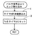
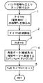
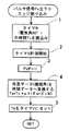
図5は、パルサが第1のパルスVs1を発生したときに実行されるパルサ信号立上りエッジ割り込みルーチンで、このルーチンでは、ステップ1で回転子の1回転の時間を計測しているタイマNの計測値を読み込み、ステップ2で制御電圧発生タイミング推測用計測時間TaをU相の交流制御電圧を発生させるタイミングを計測するタイマUにセットしてその計測を開始させる。タイマNの計測値は、図4のルーチンにおいて角度を時間データに換算する際に用いる回転速度を演算するために使用される。この回転速度の演算はメインルーチンで行われる。
【0090】
図6はタイマUが第1の予測経過時間Taの計測を完了したときに実行されるタイマU割り込みルーチンで、このルーチンではステップ1で第2の予測経過時間Tbを2番目以降の零点を検出するためのタイマVにセットしてその計測を開始させ、ステップ2でスイッチングパターンデータフラグSWPDを1とする。次いでステップ3で第1のオンオフパターンを発生させた後メインルーチンに復帰する。
【0091】
図7は、タイマVがセットされた計測値(第2の予測経過時間)Tbを計測する毎に実行されるタイマV割り込みルーチンで、このルーチンでは先ずステップ1でフラグSWPDが1であるか否かを判定し、このフラグが1である場合には、ステップ2に進んで第2の予測経過時間TbをタイマVにセットしてその計測を開始させる。次いでステップ3で第2のオンオフパターンを発生させた後ステップ4でフラグSWPDをインクリメントしてメインルーチンに復帰する。
【0092】
ステップ1でフラグSWPDが1でないときにはステップ5に進んでフラグSWPDが2であるか否かを判定し、その結果フラグが2であるときには、ステップ6で零点推測用計測時間TbをタイマVにセットしてその計測を開始させる。次いでステップ7で第3のオンオフパターンを発生させた後ステップ8でフラグSWPDをインクリメントしてメインルーチンに復帰する。
【0093】
ステップ5でフラグSWPDが2でないときにはステップ9に進んでフラグSWPDが3であるか否かを判定し、その結果フラグが3であるときには、ステップ10で零点推測用計測時間TbをタイマVにセットしてその計測を開始させる。次いでステップ11で第4のオンオフパターンを発生させた後ステップ12でフラグSWPDをインクリメントしてメインルーチンに復帰する。
【0094】
ステップ9でフラグSWPDが3でないときにはステップ13に進んでフラグSWPDが4であるか否かを判定し、その結果フラグが4であるときには、ステップ14で零点推測用計測時間TbをタイマVにセットしてその計測を開始させる。次いでステップ15で第5のオンオフパターンを発生させた後ステップ16でフラグSWPDをインクリメントしてメインルーチンに復帰する。
【0095】
ステップ13でフラグSWPDが4でないと判定されたときにはステップ17に進んで第6のスイッチパターンを発生させてメインルーチンに復帰する。
【0096】
本実施形態では、図4のルーチンにより制御電圧位相角決定手段21が構成され、図5の割り込みルーチンと、図6の割り込みルーチンのステップ1及び2と、図7の割り込みルーチンのステップ1,2,4,5,6,8,9,10,12,13,14及び16により制御電圧零点推測手段22が構成される。
【0097】
また図6の割り込みルーチンのステップ3、及び図7の割り込みルーチンのステップ3,7,11,15及び17によりオンオフパターン発生手段23が構成される。
【0098】
なお回転速度検出手段20は、図5のステップ1で読み込んだ時間からを回転速度を演算する過程(メインルーチンで行われる)により実現される。
【0099】
マイクロプロセッサはインバータの制御の外に、内燃機関を運転するために必要な点火装置の制御や、燃料噴射装置の制御などをも行うが、これらの制御は通常行われている方法により行われるので、その説明は省略する。
【0100】
上記のように、本発明においては、ホール素子のような半導体素子からなるセンサを用いることなく、磁石発電機と共に内燃機関のカバー内に配置しても支障を来さない磁束変化検出形(上記の例では誘導子形)の信号発生装置を用いて回転子の回転角度位置を検出することにより、発電機の電機子コイルの誘起電圧に対して所定の位相角を有する交流制御電圧を発生させて、この交流制御電圧を電機子コイルに印加することにより発電機の出力調整を行うので、内燃機関により駆動される磁石発電機を用いてバッテリを充電する発電装置の出力調整を、発熱を伴う短絡形の電圧調整器を用いることなく行わせることができる。
【0101】
また磁石発電機を機関のカバー内に配置することができるため、内燃機関の構成を何ら変更することなく、本発明を適用することができる。
【0102】
更に、磁石発電機の出力調整手段として従来から用いられていた短絡形の電圧調整器は、磁石発電機の出力を抑制することはできても増大させることはできなかったが、本発明によれば、電機子コイルの誘起電圧に対する交流制御電圧の位相を遅角側に変化させることにより、発電機の出力を増大させることもできるため、従来の短絡形の電圧調整器を用いる場合に比べて発電出力の制御に多様性を持たせることができる。
【0103】
上記の例では、パルサがリラクタの前端側エッジを検出したときに発生するパルスを基準にして交流制御電圧の零点を検出するようにしているが、パルサがリラクタの後端側エッジを検出したときに発生するパルスを基準にして交流制御電圧の各零点の検出を行わせることもできる。
【0104】
図1に示した例では、回転子に設けられる磁石界磁が2極に構成されているが、更に多極の磁石界磁が用いられる場合にも本発明を適用することができる。
【0105】
図8及び図9は、本発明の第2の実施形態で用いる磁石発電機と信号発生装置とを示したもので、この実施形態では、磁石界磁が8極に構成されている。
【0106】
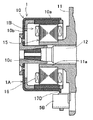
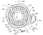
図8及び図9において10は鉄などの強磁性材料によりほぼカップ状を呈するように構成された回転子ヨークで、この回転子ヨークは、その底壁部10bの中央部に取り付けられたボス部10cが内燃機関11のクランク軸12に嵌着されて機関に取り付けられている。
【0107】
本実施形態では、回転子ヨーク10の周壁部10aの内周に、等角度間隔で配置された8個の円弧状の永久磁石M1ないしM8が接着により取り付けられていて、回転子ヨーク10の周方向にN極とS極とが交互に並ぶように、永久磁石M1ないしM8が交互に着磁方向を異にして径方向に着磁されることにより、回転子ヨークの内周に8極の磁石界磁が構成されている。回転子ヨーク10と永久磁石M1ないしM8とにより磁石発電機の回転子1Aが構成されている。回転子1Aは、機関の正回転時に図8において時計方向に回転させられる。
【0108】
回転子1Aの内側には、固定子1Bが配置されている。この固定子は、環状に形成された継鉄部Yの外周部から12個の突極部P1ないしP12を放射状に突出させた構造を有する星形環状の電機子鉄心15と、電機子鉄心の突極部P1ないしP12にそれぞれ巻回されたコイル16とからなっている。
【0109】
図示の例では、突極部P1,P4,P7,P10にそれぞれ巻回されたコイルが直列に接続されてU相の電機子コイルLuが構成され、突極部P2,P5,P8,P11にそれぞれ巻回されたコイルが直列に接続されてV相の電機子コイルLvが構成されている。また突極部P3,P6,P9,P12にそれぞれ巻回されたコイルが直列に接続されてW相の電機子コイルLwが構成されている。U相ないしW相の電機子コイルLuないしLwは星形結線され、図1に示した例と同様に、これらの電機子コイルの中性点と反対側の端末部から3相の出力端子1u,1v及び1wが引き出されている。
【0110】
図9に示したように、固定子1Bは、内燃機関11のクランク軸12を同心的に取り囲む状態で機関のケースの一部に形成された円筒状のボス部11aの外周に嵌合されて機関に取り付けられ、電機子鉄心15の突極部P1ないしP12のそれぞれの先端に形成された磁極部が回転子1Aの磁石界磁の磁極に所定のギャップを介して対向させられている。
【0111】
回転子ヨーク10の周壁部10aの外周には、該周壁部の周方向に延びる円弧状の突起からなる1つのリラクタ17が形成され、このリラクタ17と回転子ヨーク10とにより信号発生用ロータ5Aが構成されている。
【0112】
信号発生用ロータ5Aの側方には、パルサ5Bが配置され、ロータ5Aとパルサ5Bとにより信号発生装置5が構成されている。パルサ5Bはリラクタ17に対向する磁極部を先端に有する鉄心と、該鉄心に巻回された信号コイルと、該鉄心に磁気結合された永久磁石とを備えた周知のもので、図9に示したように、機関11のケースに固定されて、その磁極部が回転子ヨークのリラクタ17が設けられた領域に対向させられている。
【0113】
図示の例では、リラクタ17の回転方向の前端側のエッジが磁石界磁のN極とS極との間の中心位置(磁極間中心位置)θmoにあり、パルサ5Bの中心θpo(図8参照)が、発電機のU相の交流誘起電圧に対する交流制御電圧の進角度が0度になる基準位置θou(この例では、U相の電機子コイルLuの交流誘起電圧の正の半波が立ち上がる直前の零点が生じる位置)に対して電気角でβ°ずれた位置に配置されている。
【0114】
なお図8において、θuは、U相の電機子コイルが巻かれた突極部の中心位置を示している。
【0115】
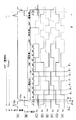
図8及び図9に示したように磁石発電機及び信号発生装置を構成した場合に信号発生装置及び波形整形装置が発生する信号の波形、及びインバータ駆動部がインバータに与える駆動信号Su,Sv,Sw,Sx,Sy,Szの波形を示す波形図を図10に示した。
【0116】
パルサ5Bは、図10(A)に示すように、発電機の回転子の回転角度位置(機関のクランク軸の回転角度位置)θが予め設定された第1の位置θs1に一致したときに第1のパルスVs1を発生し、回転角度位置θが機関の低速時の点火位置として用いられる第2の位置θs2に一致したときに負極性の第2のパルスVs2を発生する。パルサ5Bが第1のパルスVs1を発生する位置θs1は、機関の点火位置の最大進角位置よりも進角した位置に設定され、第2の位置θs2は機関の上死点に近い位置に設定されている。
【0117】
この場合、制御電圧零点推測手段22は、パルサ5Bが第1のパルスを発生する位置θs1からU相の交流制御電圧の発生位置θ1までの角度Δθ=β+θaを第1の零点計測用角度として演算し、回転速度検出手段により検出されている回転速度を用いて、この角度を時間データに変換して第1の予測経過時間Taを求める。また電気角で60°の角度を回転速度を用いて時間データに変換して、第2の予測経過時間Tbを求める。
【0118】
そして、第1のパルスVs1が発生したときにタイマに第1の予測経過時間Taの計測を開始させ、その計測が完了するタイミングをU相の交流制御電圧の発生タイミング(最初の零点)と推測する。また各零点が推測される毎に第2の予測経過時間Tbを計測することにより、3相の交流制御電圧の2番目移行の目標零点を推測する。
【0119】
オンオフパターン発生手段23は、電気角で360°の区間で順次予測される目標零点θ1 ,θ2 ,…,θ6 でそれぞれ前記と同様のオンオフパターンを発生させる。
【0120】
なお図10において破線で示した部分は、紙面のスペースの関係上実際の寸法よりも縮小して示されている。
【0121】
図8及び図9に示すように磁石発電機及び信号発生装置を構成する場合にコントローラのマイクロプロセッサが実行するプログラムの要部のアルゴリズムを示すフローチャートを図11ないし図14に示した。なおこの例では、図11ないし図14のフローチャートで用いている符号を説明するための注書きを、図11に一括して示してある。
【0122】
図11は、一定のサンプリング間隔でバッテリ2の両端の電圧をサンプリングする毎に実行される制御電圧位相角及びU相制御電圧零点計算ルーチンで、このルーチンにおいては、先ずステップ1において、バッテリ電圧Vbが設定電圧を与える基準電圧Vref 以上であるか否かを判定する。その結果Vb≧Vref であると判定されたときには、ステップ2に進んで、新たな位相角θaを前回の位相角θbよりも一定角度θcだけ進角させた角度θb−θcとしてメインルーチンに復帰する。ステップ1においてVb<Vref と判定された場合には、ステップ3に進んで新たな位相角θaを前回の位相角θbよりも一定角度θcだけ遅角させた角度θb+θcとしてメインルーチンに復帰する。
【0123】
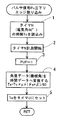
図12は、パルサが第1のパルスVs1を発生したときに実行されるパルサ信号立上りエッジ割り込みルーチンで、このルーチンでは、ステップ1で回転子の1回転の時間を計測しているタイマNの計測値(機械角で360°を回転するのに要した時間)Tcを読み込み、ステップ2でタイマNによる次の1回転の時間の計測を開始させる。またステップ3で第1の予測経過時間Ta[=Tc×(θa+β)/360]を演算し、ステップ4でこの第1の予測経過時間TaをU相の交流制御電圧を発生させるタイミングを計測するタイマUにセットしてその計測を開始させる。またステップ5において、1回転の時間Tcと発電機の極対数PCD(本実施形態では4)とを用いて、電気角で60°の区間に相当する第2の予測経過時間Tb[=Tc×60/(PCD×360)を演算してメインルーチンに戻る。
【0124】
図13はタイマUが第1の予測経過時間Taの計測を完了したときに実行されるタイマU割り込みルーチンで、このルーチンではステップ1で第2の予測経過時間Tbを2番目以降の零点を検出するためのタイマVにセットしてその計測を開始させ、ステップ2でタイマUを解除する。次いでステップ3でスイッチングパターンデータフラグSWPDを0とし、ステップ4でフラグSWPDの値に対して図15に示したSWPDマップ(スイッチパターンデータマップ)を検索して、ステップ5で検索したスイッチパターンマップデータをインバータ駆動部24にセットする。その後、ステップ6でフラグSWPDを1とし、ステップ7で極対数カウンタPCCを初期化してメインルーチンに戻る。
【0125】
図14は、タイマVがセットされた計測値Tbを計測する毎に実行されるタイマV割り込みルーチンで、このルーチンにおいては、ステップ1において極対数カウンタPCCの計数値がPCD(この例では4)に等しいか否かをチェックする。その結果、PCC=PCDでないときには、ステップ2に進んで極対数カウンタPCCの計数値を1だけインクリメントし、ステップ3でタイマVに第2の予測経過時間Tbをセットしてその計測を開始させる。次いでステップ4でフラグSWPDの値に対して図15に示したSWPDマップを検索し、ステップ5において検索したスイッチパターンデータをインバータ駆動部24にセットする。
【0126】
次いでステップ6でフラグSWPDの値が5であるか否かを判定し、その結果SWPDの値が5でない場合には、ステップ7でフラグSWPDの値を1だけインクリメントしてメインルーチンに戻る。またステップ6でフラグSWPDの値が5であると判定されたときには、ステップ8に移行してフラグSWPDの値を0とし、メインルーチンに復帰する。
【0127】
図14に示したルーチンにおいて、ステップ1で極対数カウンタPCCの値がPCDに等しくないと判定されたときには、ステップ9に進んでフラグSWPDが5に等しいか否かを判定し、その結果フラグSWPDが5に等しくないと判定されたときには、ステップ3に移行する。またステップ9においてフラグSWPDが5に等しいと判定されたときには、ステップ10に進んでタイマVを解除した後、ステップ4に移行する。
【0128】
本実施形態では、図11のルーチンにより制御電圧位相角決定手段21が構成され、図12の割り込みルーチンのステップ1及び2により回転速度検出手段20が構成される。また図12の割り込みルーチンのステップ3ないし5と、図13の割り込みルーチンと、図14の割り込みルーチンのステップ1ないし3及び10とにより、制御電圧零点推測手段22が構成される。
【0129】
また図14の割り込みルーチンのステップ4及び5によりオンオフパターン発生手段23が構成される。
【0130】
図8及び図9に示した例では、リラクタ及びパルサを1つずつ設けて、機械角で360°毎に制御電圧発生タイミング推測用計測時間Taと、零点推測用計測時間Tbとを更新するようにしたが、本発明は上記のように信号発生装置を構成する場合に限定されるものではなく、更に多くのリラクタを設けて短い間隔で、制御電圧発生タイミング推測用計測時間Taと、零点推測用計測時間Tbとを更新して交流制御電圧の位相を精度よく定めるようにすることができる。
【0131】
図16及び図17は、本発明の第3の実施形態で用いる磁石発電機と信号発生装置とを示したもので、この実施形態では、回転子ヨーク10の外周に4つのリラクタ17Aないし17Dを設けて、これらのリラクタの前端側エッジ及び後端側エッジを1つのパルサ5Bで検出するように信号発生装置5を構成している。 図16及び図17に示した例においては、リラクタ17Aないし17Dのそれぞれが45°(=360°/8)の極弧角を有するように形成されて、等角度間隔で配置されている。各リラクタの極弧角(45°)は電気角で180°に相当する。また各リラクタの回転方向の前端側エッジ17aは磁石界磁の隣り合うN極とS極との間の中立位置にあり、各リラクタの回転方向の後端側エッジ17bは、磁石界磁の他の隣り合うN極とS極との間の中立位置にある。
【0132】
図16及び図17に示したように磁石発電機及び信号発生装置を構成した場合に信号発生装置5及び波形整形回路18が発生する信号の波形及びインバータ駆動部がインバータに与える駆動信号の波形を図18に示した。
【0133】
この例では、信号発生装置5が電気角で180°の間隔で第1のパルスVs1及び第2のパルスVs2を発生する。信号発生装置5はまた電気角で360°の間隔で各パルス信号を発生する。またオンオフパターン発生手段23は、電気角で360°の区間に60°(電気角)間隔で設定される6つの目標零点θ1 ないしθ6 でそれぞれ所定のオンオフパターンを発生する。
【0134】
信号発生装置を図16及び図17に示すように構成して、パルサ5Bが各リラクタの回転方向の前端側エッジを検出する毎に制御電圧発生タイミング推測用計測時間Ta及び零点推測用計測時間Tbの計測を開始するようにすれば、機械角で90°毎に回転速度を演算して、第1の予測経過時間Ta及び第2の予測経過時間Tbを更新することができるため、図8及び図9に示した信号発生装置を用いる場合よりも交流制御電圧の位相を正確に定めて、制御の精度を高めることができる。
【0135】
図16及び図17に示したように信号発生装置及び磁石発電機を構成する場合に、コントローラ4のマイクロプロセッサが図2に示した機能実現手段を構成するために実行するプログラムのアルゴリズムを示すフローチャートを図19ないし図23に示した。なお図19に付記された注書きは、図19ないし図23にそれぞれ示したフローチャートで用いている符号をまとめて示したものである。
【0136】
図19は、一定のサンプリング間隔でバッテリ2の両端の電圧をサンプリングする毎に実行される制御電圧位相角及びU相制御電圧零点計算ルーチンで、このルーチンのアルゴリズムは、図11に示されたルーチンと同様である。
【0137】
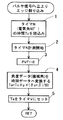
図20は、パルサの出力信号を波形整形する波形整形回路18から得られるパルサ信号Pの立上りが検出されたときに(第1のパルスVs1を発生したときに)実行されるパルサ信号立上りエッジ割り込みルーチンで、このルーチンでは、ステップ1で電気角で180°の区間を回転子が回転するのに要した時間を計測しているタイマNの計測値(電気角180°に相当する時間)Tcを読み込み、ステップ2でタイマNによる次の180°の区間に相当する時間の計測を開始させる。またステップ3で第1の予測経過時間Ta[=Tc×p×(θa+β)/180](pは磁石界磁の極対数)を演算し、ステップ4でこの第1の予測経過時間TaをU相の交流制御電圧を発生させるタイミングを計測するタイマUにセットしてその計測を開始させる。またステップ5において、電気角180°に相当する時間Tcを用いて、電気角で60°の区間に相当する第2の予測経過時間Tb[=Tc×60/180)を演算し、ステップ6においてパルサエッジフラグPEDGEを0とした後メインルーチンに戻る。
【0138】
パルサエッジフラグPEDGEは、波形整形回路18の出力信号Pの立上りで0とされ、信号Pの立下りで1とされるフラグである。
【0139】
図21は、パルサ信号Pの立下りエッジが検出されたとき(第2のパルスVs2が発生したとき)に実行されるパルサ信号立下りエッジ割り込みで、この割り込みルーチンにおいては、ステップ1で電気角で180°の区間を回転子が回転するのに要した時間を計測しているタイマNの計測値(電気角180°に相当する時間)Tcを読み込み、ステップ2でタイマNによる次の180°の区間に相当する時間の計測を開始させる。またステップ3で第1の予測経過時間Ta[=Tc×p×(θa+β)/180]を演算し、ステップ4でこの第1の予測経過時間TaをU相の交流制御電圧を発生させるタイミングを計測するタイマUにセットしてその計測を開始させる。またステップ5において、電気角180°に相当する時間Tcを用いて、電気角60°の区間に相当する第2の予測経過時間Tb[=Tc×60/180)を演算し、ステップ6においてパルサエッジフラグPEDGEを1とした後メインルーチンに戻る。
【0140】
図22は、タイマUが第1の予測経過時間Taの計測を完了したときに実行されるタイマU割り込みルーチンで、このルーチンではステップ1で第2の予測経過時間Tbを2番目以降の零点を検出するためのタイマVにセットしてその計測を開始させ、ステップ2でタイマUを解除する。次いでステップ3でパルサエッジフラグPEDGEが0であるか否かを判定し、フラグPEDGEが0であるときにはステップ4に進んでフラグSWPDを0とする。その後ステップ5においてフラグSWPDの値に対して図15のマップを検索し、ステップ6で検索したスイッチパターンマップデータをインバータ駆動部24にセットする。その後、ステップ7でフラグSWPDを1としてメインルーチンに戻る。ステップ3でパルサエッジフラグPEDGEが0でない(1である)と判定されたときには、ステップ8に進んでフラグSWPDを3とした後、ステップ5に進む。
【0141】
図23は、タイマVがセットされた計測値Tbを計測する毎に実行されるタイマV割り込みルーチンで、このルーチンにおいては、ステップ1においてフラグSWPDの値が2または5であるか否かを判定し、その結果フラグSWPDが2または5であるときには、ステップ2に進んで改めて第2の予測経過時間TbをタイマVにセットする。
【0142】
次いでステップ3において、フラグSWPDの値に対して図15に示したSWPDマップを検索し、ステップ4において検索したスイッチパターンデータをインバータ駆動部24にセットする。次いでステップ5でフラグSWPDの値が2または5であるか否かを判定し、その結果SWPDの値が2または5でない場合には、ステップ6でフラグSWPDの値を1だけインクリメントしてメインルーチンに戻る。またステップ5でフラグSWPDの値が2または5であると判定されたときには、何もしないでメインルーチンに復帰する。ステップ1においてフラグSWPDが2または5であると判定されたときには、ステップ7に進んでタイマVを解除した後ステップ3に移行する。
【0143】
本実施形態においては、図19のルーチンにより制御電圧位相角決定手段21が構成され、図20の割り込みルーチンのステップ1及び2と図21のルーチンのステップ1及び2により回転速度検出手段20が構成される。また図20の割り込みルーチンのステップ3ないし6と、図21の割り込みルーチンのステップ3ないし6と、図22の割り込みルーチンのステップ3ないし5とにより、制御電圧零点推測手段22が構成され、図14の割り込みルーチンのステップ4及び5によりオンオフパターン発生手段23が構成される。
【0144】
図24及び図25は本発明の第4の実施形態で用いる磁石発電機と信号発生装置の構成例を示したものである。この例では、図16及び図17に示した例と同様に45°の極弧角を有する4つのリラクタ17Aないし17Dを等角度設けた上で、U,V,W相にそれぞれ対応する3つのパルサ5Buないし5Bwを120°間隔で設けている。
【0145】
図24及び図25に示すように信号発生装置を構成する場合にパルサ5Buない5Bwが発生するパルス信号Vsu,Vsv,Vswの波形、波形整形回路18がこれらのパルス信号を波形整形して出力するパルサ信号Pu,Pv,Pwの波形、及びインバータ駆動部がインバータに与える駆動信号Su,Sv,Sw,Sx,Sy,Szの波形を図26に示した。
【0146】
また図24及び図25に示すように信号発生装置を構成する場合に図2に示した機能実現手段を構成するためにコントローラ4のマイクロプロセッサが実行するプログラムのアルゴリズムを示すフローチャートを図27ないし図36に示した。
【0147】
この実施形態においては、3つのパルサ5Buないし5Bwが電気角で60°の間隔で一連のパルス信号Vsu1 ,Vsw2 ,Vsv1 ,Vsu2 ,Vsw1 ,Vsv2 ,…を発生する。本実施形態では、パルス信号Vsu1 が発生してからパルス信号Vsw2 が発生するまでの時間、パルス信号Vsv1 が発生してからパルス信号Vsu2 が発生するまでの時間及びパルス信号Vsw1 が発生してからパルス信号Vsv2 が発生するまでの時間をそれぞれ電気角60°に相当する時間Tcとして計測し、この時間Tcから回転子の回転速度を検出する。
【0148】
またこの例では、U相のパルサ5Buが出力する第1のパルスVsu1 の発生位置を基準にしてU相の交流制御電圧を発生させる位置θ1を推測し、V相のパルサ5Bvが出力する第1のパルスVsv1 の発生位置を基準にしてV相の交流制御電圧を発生させる位置θ3を推測する。またW相のパルサ5Bwが出力する第1のパルスVsw1 の発生位置を基準にしてW相の交流制御電圧を発生させる位置θ5を推測する。更にW相のパルサ5Bw,U相のパルサ5Bu及びV相のパルサ5Bvがそれぞれ出力する第2のパルスVsw2 ,Vsu2 及びVsv2 の発生位置を基準にしてW相の交流制御電圧が正の半波から負の半波に移行する際の零点θ2、U相の交流制御電圧が正の半波から負の半波に移行する際の零点θ4及びV相の交流制御電圧が正の半波から負の半波に移行する際の零点θ6を推測する。従って、この例では、電気角60°に相当する時間(第2の予測経過時間)Tbの計測は行わない。
【0149】
信号発生装置を図24及び図25に示すように構成する場合に、コントローラ4のマイクロプロセッサが実行するプログラムのアルゴリズムを示したフローチャートを図27ないし図36に示した。
【0150】
図27は、一定のサンプリング間隔でバッテリ2の両端の電圧をサンプリングする毎に実行される制御電圧位相角及びU相制御電圧零点計算ルーチンで、このルーチンのアルゴリズムは、図11に示されたルーチンと同様である。
【0151】
図28は、U相のパルサ信号Puの立上りが検出されたとき(パルサ5Buが第1のパルスVsu1 を発生したとき)に実行されるパルサ信号立上りエッジ割り込みルーチンで、このルーチンでは、ステップ1で電気角60°の区間を回転子が回転するのに要した時間を計測しているタイマNの計測値(電気角60°に相当する時間)Tcを読み込み、ステップ2でタイマNによる次の60°の区間に相当する時間の計測を開始させる。またステップ3でU相用パルサフラグPUFを0とし、ステップ4でパルサ信号Puの立上りエッジからU相の交流制御電圧の最初の目標零点θ1 に相当するタイミングまでの予測経過時間Ta[=Tc×p×(θa+β)/60](pは磁石界磁の極対数)を演算する。次いで、ステップ5でタイマUに第1の予測経過時間Taをセットしてその計測を開始させた後、メインルーチンに戻る。
【0152】
図29は、U相のパルサ信号Puの立下りエッジが検出されたとき(パルサ5Buが第2のパルスVsu2 を発生したとき)に実行されるパルサ信号立Pu立下りエッジ割り込みで、この割り込みルーチンにおいては、ステップ1で電気角で60°の区間を回転子が回転するのに要した時間を計測しているタイマNの計測値(電気角60°に相当する時間)Tcを読み込み、ステップ2でタイマNによる次の60°の区間に相当する時間の計測を開始させる。またステップ3でU相用パルサフラグPUFを1とし、ステップ4でU相の交流制御電圧の2番目の目標零点θ4 を与える第1の零点推測用角度θa+βを時間データに変換する演算を行って、パルサ信号Puの立下りエッジからU相の交流制御電圧の2番目の目標零点θ4 までの予測経過時間Ta[=Tc×p×(θa+β)/60]を演算し、ステップ5でこの予測経過時間TaをタイマUにセットした後、メインルーチンに戻る。
【0153】
図30はV相のパルサ信号Pvの立上りエッジが検出されたとき(パルサ5Bvが第1のパルスVsv1 を発生したとき)に実行されるパルサ信号Pv立上りエッジ割り込みルーチンで、このルーチンでは、ステップ1で電気角60°の区間を回転子が回転するのに要した時間を計測しているタイマNの計測値(電気角60°に相当する時間)Tcを読み込み、ステップ2でタイマNによる次の60°の区間に相当する時間の計測を開始させる。またステップ3でV相用パルサフラグPVFを0とし、ステップ4でパルサ信号Pvの立上りエッジからV相の交流制御電圧の最初の目標零点θ3 に相当するタイミングまでの予測経過時間Ta[=Tc×p×(θa+β)/60](pは磁石界磁の極対数)を演算する。次いで、ステップ5でタイマVに予測経過時間Taをセットしてその計測を開始させた後、メインルーチンに戻る。
【0154】
図31は、V相のパルサ信号Pvの立下りエッジが検出されたとき(パルサ5Bvが第2のパルスVsv2 を発生したとき)に実行されるパルサ信号Pv立下りエッジ割り込みルーチンで、この割り込みルーチンにおいては、ステップ1で電気角で60°の区間を回転子が回転するのに要した時間を計測しているタイマNの計測値(電気角60°に相当する時間)Tcを読み込み、ステップ2でタイマNによる次の60°の区間に相当する時間の計測を開始させる。またステップ3でV相用パルサフラグPVFを1とし、ステップ4でV相の交流制御電圧の2番目の目標零点θ6 を与える第1の零点推測用角度θa+βを時間データに変換する演算を行って、パルサ信号Pvの立下りエッジからV相の交流制御電圧の2番目の目標零点θ6 までの予測経過時間Ta[=Tc×p×(θa+β)/60]を演算し、ステップ5でこの予測経過時間TaをタイマVにセットした後、メインルーチンに戻る。
【0155】
図32はW相のパルサ信号Pwの立上りエッジが検出されたとき(パルサ5Bwが第1のパルスVsw1 を発生したとき)に実行されるパルサ信号Pw立上りエッジ割り込みルーチンで、このルーチンでは、ステップ1で電気角60°の区間を回転子が回転するのに要した時間を計測しているタイマNの計測値(電気角60°に相当する時間)Tcを読み込み、ステップ2でタイマNによる次の60°の区間に相当する時間の計測を開始させる。またステップ3でW相用パルサフラグPWFを0とし、ステップ4でパルサ信号Pwの立上りエッジからW相の交流制御電圧の最初の目標零点θ5 に相当するタイミングまでの予測経過時間Ta[=Tc×p×(θa+β)/60](pは磁石界磁の極対数)を演算する。次いで、ステップ5でタイマWに予測経過時間Taをセットしてその計測を開始させた後、メインルーチンに戻る。
【0156】
図33は、W相のパルサ信号Pwの立下りエッジが検出されたとき(パルサ5Bwが第2のパルスVsw2 を発生したとき)に実行されるパルサ信号Pw立下がりエッジ割り込みで、この割り込みルーチンにおいては、ステップ1で電気角で60°の区間を回転子が回転するのに要した時間を計測しているタイマNの計測値(電気角60°に相当する時間)Tcを読み込み、ステップ2でタイマNによる次の60°の区間に相当する時間の計測を開始させる。またステップ3でW相用パルサフラグPWFを1とし、ステップ4でW相の交流制御電圧の2番目の目標零点θ2 を与える第1の零点推測用角度θa+βを時間データに変換する演算を行って、パルサ信号Pwの立下りエッジからW相の交流制御電圧の2番目の目標零点θ2 までの予測経過時間Ta[=Tc×p×(θa+β)/60]を演算し、ステップ5でこの予測経過時間TaをタイマVにセットした後、メインルーチンに戻る。
【0157】
図34は、タイマUが予測経過時間Taの計測を完了したときに実行されるタイマU割り込みルーチンで、この割り込みルーチンでは、ステップ1においてタイマUを解除した後、ステップ2でU相用パルサフラグPUFが0であるか否かを判定し、PUFが0であるときにはステップ3に進んでオンオフパターン(1,0,1,0,1,0)を発生させる。またステップ2でPUFが0でないと判定されたときにはステップ4に進んでオンオフパターン(0,1,0,1,0,1)を発生させる。
【0158】
図35はタイマVが予測経過時間Taの計測を完了したときに実行されるタイマV割り込みルーチンで、この割り込みルーチンでは、ステップ1においてタイマVを解除した後、ステップ2でV相用パルサフラグPVFが0であるか否かを判定し、PVFが0であるときにはステップ3に進んでオンオフパターン(1,1,0,0,0,1)を発生させる。またステップ2でPVFが0でないと判定されたときにはステップ4に進んでオンオフパターン(0,0,1,1,1,0)を発生させる。
【0159】
図36は、タイマWが予測経過時間Taの計測を完了したときに実行されるタイマW割り込みルーチンで、この割り込みルーチンでは、ステップ1においてタイマWを解除した後、ステップ2でW相用パルサフラグPWFが0であるか否かを判定し、PWFが0であるときにはステップ3に進んでオンオフパターン(0,1,1,1,0,0)を発生させる。またステップ2でPWFが0でないと判定されたときにはステップ4に進んでオンオフパターン(1,0,0,0,1,1)を発生させる。
【0160】
本実施形態では、図27のルーチンにより制御電圧位相角決定手段21が構成され、図28ないし図33の割り込みルーチンのそれぞれのステップ1及び2により回転速度検出手段20が構成される。また図28ないし図33の割り込みルーチンのそれぞれのステップ3ないし5により制御電圧零点推測手段22が構成される。更に図34ないし図36の割り込みルーチンによりオンオフパターン発生手段23が構成される。
【0161】
図37及び図38は本発明の第5の実施形態で用いる磁石発電機及び信号発生装置の構成例を示したもので、この例では、図16及び図17に示した例と同様に設けられた4つのリラクタ17Aないし17Dのうち、1つのリラクタ17Cが、回転子ヨークの外周面からの高さが高い第1の部分17C1と、該第1の部分よりも回転方向の後方側にあって該第1の部分よりも高さが低い第2の部分17C2とを有する2段リラクタからなっている。リラクタ17C全体の極弧角は他のリラクタ17A,17B及び17Dの極弧角と同じである。そしてこの例では、パルサ5Bがリラクタ17Cの回転方向の前端側エッジ17Caを検出したときに発生するパルスが、他のリラクタの回転方向の前端側のエッジを検出したときに発生するパルスとともに、交流制御電圧の発生タイミングと零点とを求めるために用いられ、パルサがリラクタ17Cの第1の部分17C1と第2の部分17C2との境界部分に形成されたエッジ17Ccを検出したときに発生するパルスが、内燃機関の点火時期を求める際の基準位置を検出するためのパルスとして用いられる。即ちこの例では、リラクタ17Cが、交流制御電圧を発生させるために用いるリラクタと、内燃機関の点火時期を検出する際の基準となる信号を発生させるために用いられる点火用のリラクタとを兼ねている。
【0162】
このように、回転子ヨークに設けるリラクタを交流制御電圧発生用のリラクタと点火用のリラクタとに兼用するようにすると、点火用のリラクタ及びパルサを別個に設ける必要がなくなるため、信号発生装置の構成を簡単にすることができる。
【0163】
図37及び図38に示した例においても、パルサを各相毎に設けることができる。
【0164】
上記の例では、磁石発電機として3相交流出力を発生するものを用いたが、単相の磁石発電機を用いる場合にも本発明を適用することができ、2相交流出力または4相以上の多相交流出力を発生する磁石発電機を用いる場合にも本発明を適用することができる。
【0165】
上記の例では、磁石発電機の回転子ヨークの外周に信号発生装置のリラクタを形成したが、本発明は、このように回転子ヨークの外周にリラクタを設ける場合に限定されるものではなく、回転子のボス部の外周や、回転子ヨークとは別個に設けた回転円板の外周などにリラクタを設けるようにしてもよい。
【0166】
上記の例では、磁石発電機として回転子外転形のものを用いたが、回転子内転形の磁石発電機を用いる場合にも本発明を適用することができる。
【0167】
上記の例では、電圧蓄積手段としてバッテリを用いたが、バッテリの代わりにコンデンサを電圧蓄積手段として用いる場合(図1においてバッテリ2を省略してコンデンサCaを電圧蓄積手段として用いる場合)にも本発明を適用することができる。
【0168】
上記の各実施形態では、信号発生装置として、リラクタのエッジを検出したときにパルスを発生する誘導子形のものを用いたが、信号発生装置は、内燃機関の高い温度に曝されたときに破壊する部品(特に半導体部品)を用いずに、回転子の回転角度位置が予め定められた特定の回転角度位置に一致する毎にパルスを発生するものであればよく、誘導子形のものに限定されない。
【0169】
回転体の特定の回転角度位置で信号を発生する装置としては、種々の形式のものがあるが、内燃機関の高い温度に曝されたときに破壊することがない信号発生装置としては、磁束の変化をコイルにより検出してパルスを発生させるようにした磁束変化検出形のものを用いるのが好ましい。
【0170】
上記の各実施形態で用いた誘導子形の信号発生装置は、磁束変化検出形の信号発生装置として広く用いられているものであるが、この誘導子形の信号発生装置に代えて、例えば、回転子ヨークに永久磁石を貼り付けて構成した信号発生用ロータと、該信号発生用ロータの磁石に対向する磁極部を有する鉄心に信号コイルを巻回して構成した信号発生用ステータとを備えて、信号発生用ロータの磁石が信号発生用ステータの鉄心の磁極部の位置を通過する際に信号コイルと鎖交する磁束に生じる変化により信号コイルにパルス信号を誘起させるようにした磁束変化検出形の信号発生装置を用いることもできる。
【0171】
また回転子ヨークの周壁部の内周に取りつけられた永久磁石から生じる磁束の一部を外部に漏洩させるための孔を回転子ヨークの周壁部に設けるとともに、該回転子ヨークの周壁部の孔に対向する磁極部を有する鉄心に信号コイルを巻回して構成した信号発生用ステータを回転子ヨークの周壁部の外側に配置して、回転子ヨークの周壁部に設けた孔が信号発生用ステータの鉄心の磁極部の位置を通過する際に生じる磁束の変化により信号コイルにパルス信号を誘起させるようにした磁束変化検出形の信号発生装置を用いることもできる。
【0172】
【発明の効果】
以上のように、本発明によれば、磁石発電機と共に内燃機関のカバー内に配置しても支障を来さない磁束変化検出形の信号発生装置を用いて回転子の回転角度位置を検出することにより、発電機の電機子コイルの誘起電圧に対して所定の位相角を有する交流制御電圧を発生させるようにしたので、内燃機関により駆動される磁石発電機を用いてバッテリを充電する発電装置の出力調整を大きな発熱を伴うことなく行わせることができるという利点が得られる。
【0173】
また本発明によれば、発電機の出力が過大になったときに電機子コイルの誘起電圧に対する交流制御電圧の位相を進角側に変化させることにより出力を抑制できるだけでなく、交流制御電圧の位相を遅角側に変化させることにより、発電機の出力を増大させることもできるため、従来の短絡形の電圧調整器を用いる場合に比べて発電出力の制御に多様性を持たせることができる。
【図面の簡単な説明】
【図1】 本発明の第1の実施形態の全体的な構成を示した回路図である。
【図2】 本発明に係わる発電装置において用いるコントローラの構成例をハードウェアの構成とともに示したブロック図である。
【図3】 図1の実施形態の動作を説明するための信号波形図である。
【図4】 図1の実施形態においてコントローラのマイクロプロセッサが実行するプログラムの制御電圧位相角及びU相制御電圧零点計算ルーチンのアルゴリズムを示したフローチャートである。
【図5】 図1の実施形態においてコントローラのマイクロプロセッサが実行するプログラムのパルサ信号立上りエッジ割り込みルーチンのアルゴリズムを示したフローチャートである。
【図6】 図1の実施形態においてコントローラのマイクロプロセッサが実行するプログラムのタイマU割り込みルーチンのアルゴリズムを示したフローチャートである。
【図7】 図1の実施形態においてコントローラのマイクロプロセッサが実行するプログラムのタイマV割り込みルーチンのアルゴリズムを示したフローチャートである。
【図8】 本発明の第2の実施形態で用いる磁石発電機及び信号発生装置の構成例を示した正面図である。
【図9】 図8に示した磁石発電機及び信号発生装置を機関に取りつけた状態を示した断面図である。
【図10】 本発明の第2の実施形態の各部の信号波形を示した波形図である。
【図11】 本発明の第2の実施形態においてマイクロプロセッサが実行する制御電圧位相角及びU相制御電圧零点計算ルーチンのアルゴリズムを示したフローチャートである。
【図12】 本発明の第2の実施形態においてマイクロプロセッサが実行するパルサ信号立上りエッジ割り込みルーチンのアルゴリズムを示したフローチャートである。
【図13】 本発明の第2の実施形態においてマイクロプロセッサが実行するタイマU割り込みルーチンのアルゴリズムを示したフローチャートである。
【図14】 本発明の第2の実施形態においてマイクロプロセッサが実行するタイマV割り込みルーチンのアルゴリズムを示したフローチャートである。
【図15】 第2の実施形態及び第2の実施形態で用いるスイッチパターンデータマップの構成を示した図表である。
【図16】 本発明の第3の実施形態で用いる磁石発電機及び信号発生装置の構成例を示した正面図である。
【図17】 図16に示した磁石発電機及び信号発生装置を機関に取りつけた状態を示した断面図である。
【図18】 本発明の第3の実施形態の各部の信号を示した波形図である。
【図19】 本発明の第3の実施形態においてマイクロプロセッサが実行する制御電圧位相角及びU相制御電圧零点計算ルーチンのアルゴリズムを示したフローチャートである。
【図20】 本発明の第3の実施形態においてマイクロプロセッサが実行するパルサ信号立上りエッジ割り込みルーチンのアルゴリズムを示したフローチャートである。
【図21】 本発明の第3の実施形態においてマイクロプロセッサが実行するパルサ信号立下りエッジ割り込みルーチンのアルゴリズムを示したフローチャートである。
【図22】 本発明の第3の実施形態においてマイクロプロセッサが実行するタイマU割り込みルーチンのアルゴリズムを示したフローチャートである。
【図23】 本発明の第3の実施形態においてマイクロプロセッサが実行するタイマV割り込みルーチンのアルゴリズムを示したフローチャートである。
【図24】 本発明の第4の実施形態で用いる磁石発電機及び信号発生装置の構成例を示した正面図である。
【図25】 図24の磁石発電機及び信号発生装置を機関に取りつけた状態を示した断面図である。
【図26】 本発明の第4の実施形態の各部の信号波形を示した波形図である。
【図27】 本発明の第4の実施形態においてマイクロプロセッサが実行するプログラムの制御電圧位相角及びU相制御電圧零点計算ルーチンのアルゴリズムを示したフローチャートである。
【図28】 本発明の第4の実施形態においてマイクロプロセッサが実行するプログラムのパルス信号Pu立上りエッジ割り込みルーチンのアルゴリズムを示したフローチャートである。
【図29】 本発明の第4の実施形態においてマイクロプロセッサが実行するプログラムのパルス信号Pu立下りエッジ割り込みルーチンのアルゴリズムを示したフローチャートである。
【図30】 本発明の第4の実施形態においてマイクロプロセッサが実行するプログラムのパルス信号Pv立上りエッジ割り込みルーチンのアルゴリズムを示したフローチャートである。
【図31】 本発明の第4の実施形態においてマイクロプロセッサが実行するプログラムのパルス信号Pv立下りエッジ割り込みルーチンのアルゴリズムを示したフローチャートである。
【図32】 本発明の第4の実施形態においてマイクロプロセッサが実行するプログラムのパルス信号Pw立上りエッジ割り込みルーチンのアルゴリズムを示したフローチャートである。
【図33】 本発明の第4の実施形態においてマイクロプロセッサが実行するプログラムのパルス信号Pw立下りエッジ割り込みルーチンのアルゴリズムを示したフローチャートである。
【図34】 本発明の第4の実施形態においてマイクロプロセッサが実行するプログラムのタイマU割り込みルーチンのアルゴリズムを示したフローチャートである。
【図35】 本発明の第4の実施形態においてマイクロプロセッサが実行するプログラムのタイマV割り込みルーチンのアルゴリズムを示したフローチャートである。
【図36】 本発明の第4の実施形態においてマイクロプロセッサが実行するプログラムのタイマW割り込みルーチンのアルゴリズムを示したフローチャートである。
【図37】 本発明の第5の実施形態で用いる磁石発電機及び信号発生装置の構成例を示した正面図である。
【図38】 図37に示した磁石発電機及び信号発生装置を機関に取りつけた状態を示した断面図である。
【符号の説明】
1:磁石発電機、1A:回転子、1B:固定子、2:バッテリ、3:AC/DC相互変換器、4:コントローラ、5:誘導子形の信号発生装置、5A:ロータ、5B,5Bu〜5Bw:パルサ、10:回転子ヨーク、10C:回転子ヨークの周壁部、M1〜M8:永久磁石、15:電機子鉄心、17,17A〜17D:リラクタ、Lu〜Lw:電機子コイル。[0001]
BACKGROUND OF THE INVENTION
The present invention relates to a power generator that obtains electric power for driving a load by driving a magnet generator by an internal combustion engine.
[0002]
[Prior art]
2. Description of the Related Art As is well known, a magnet generator has an electric machine mounted on an armature core having a rotor having a magnetic field formed by attaching a permanent magnet to a rotor yoke, and a magnetic pole portion facing the magnetic field of the magnet field of the rotor. The stator is formed by winding a child coil.
[0003]
The rotor is attached to the rotating shaft of the prime mover, the stator is fixed to a predetermined attachment provided on the case or cover of the prime mover, and the magnetic pole portion provided on the armature core becomes the magnetic pole portion of the rotor. It is made to oppose through a predetermined gap.
[0004]
In a magnet generator, the rotor field is composed of permanent magnets, so the field is controlled in the same way as a generator with field windings to control the output of the generator. I can't.
[0005]
Therefore, as shown in
[0006]
The power generation device proposed in
[0007]
In this power generator, the output of the generator can be reduced by applying an AC control voltage having a phase angle advanced to the phase of the induced voltage of the current armature coil to the armature coil. The output of the generator can be increased by applying an AC control voltage having a phase angle retarded with respect to the phase of the induced voltage of the armature coil to the armature coil.
[0008]
That is, if the inverter is controlled so that the phase of the AC control voltage applied to the armature coil from the voltage storage means through the inverter is advanced from the current phase, the output of the generator can be reduced. If the inverter is controlled so that the phase of the AC control voltage applied to the armature coil through the phase is retarded from the current phase, the output of the generator can be increased.
[0009]
Conventionally, as the voltage regulator for controlling the output voltage of the magnet generator, a short-circuit type was used that short-circuited the output of the generator when the output voltage exceeded the target value. When the voltage regulator is used, a large short-circuit current flows through the armature coil during voltage adjustment, which causes a problem that heat generation from the armature coil increases.
[0010]
On the other hand, as described above, an AC control voltage can be applied to the armature coil, and the output of the generator is adjusted by changing the phase of the AC control voltage. Thus, since the output can be adjusted without passing a short-circuit current, it is possible to prevent the temperature of the armature coil from rising.
[0011]
In order to operate the previously proposed power generation apparatus shown in
[0012]
[Patent Document 1]
Japanese Patent Laid-Open No. 11-46456
[0013]
[Problems to be solved by the invention]
When the magnet generator is driven by an internal combustion engine, it has become clear that the following problems occur when the proposed invention is applied.
[0014]
That is, when a magnet generator is attached to an internal combustion engine, the generator temperature may exceed 150 ° C. because the generator is usually disposed within the engine cover. In this case, the sensor for detecting the rotational angle position of the magnet field is also exposed to the same temperature. However, since the Hall element is a semiconductor element, it cannot be used at a high temperature of 150 ° C.
[0015]
Therefore, in order to apply the invention described in
[0016]
SUMMARY OF THE INVENTION An object of the present invention is to adjust a generator output by applying an AC control voltage having a predetermined phase angle from a battery to an armature coil of a magnet generator driven by an internal combustion engine through an inverter. In the present invention, the timing for generating the AC control voltage can be determined without using a sensor made of a semiconductor element.
[0017]
[Means for Solving the Problems]
The present invention provides an m-phase (m is an integer of 1 or more) armature iron core having a rotor having a magnetic field of 2n poles (n is an integer of 1 or more) and a magnetic pole portion facing the magnetic field magnetic pole. A magnet generator having a stator wound with an armature coil and having a rotor driven by an internal combustion engine, and converting an AC output obtained from an m-phase armature coil of the magnet generator into a DC output An AC / DC converter comprising: an AC / DC converter for supplying voltage to the voltage storage means; and an inverter for converting the voltage at both ends of the voltage storage means into an m-phase AC voltage and applying it to the armature coil; In order to adjust the characteristics of the internal combustion engine, an internal combustion engine drive power generator including a controller that controls the inverter to apply an AC control voltage to the armature coil from the voltage storage means through the inverter is intended.
[0018]
In the present invention, there is provided a magnetic flux change detection type signal generator that detects a change in magnetic flux with a coil and generates a pulse each time the rotational angle position of the rotor coincides with a predetermined specific rotational angle position.
[0019]
The controllerThe rotation speed detection means for obtaining rotation speed information of the magnet generator based on the pulse generation interval generated by the signal generator, and the voltage at both ends of the voltage storage means by comparing the voltage at both ends of the voltage storage means with the set voltage When the voltage is lower than the set voltage, the phase angle of the AC control voltage is determined so as to delay the phase of the AC control voltage from the current phase, and when the voltage across the voltage storage means is higher than the set voltage, the AC control voltage Control voltage phase angle determination means for determining the phase angle of the AC control voltage so that the phase of the AC control voltage is advanced from the current phase, and each zero point of the AC control voltage having the phase angle determined by the control voltage phase angle determination means Is the target zero point, and the angle difference between the target zero point and the rotation angle position where the signal generator generates a specific pulse is calculated, and the calculated angle difference is obtained by the rotation speed detecting means. Using the rotational speed information of the magnet generator, it is converted into time data indicating the time required for the rotor to rotate from the rotation angle position where the specific pulse is generated to the target zero point, and the signal generator generates the specific pulse. Control voltage zero point estimation means for estimating the rotation angle position of the rotor when the measurement of the time data is completed and the rotation angle position of the rotor when the measurement of the time data is completed is to be applied to the armature coil,Estimated by this control voltage zero point estimation meansEach zeroAnd an inverter control means for controlling the inverter so as to apply an AC voltage having the same zero point to the armature coil from the voltage storage means through the inverter.
[0020]
The magnetic flux change detection type signal generator includes, for example, a rotor having a reluctator, and a pulser that generates a pulse when the front end side edge and the rear end side edge of the rotor in the rotation direction are detected. Inductor-type signal generators can be used.
[0021]
The pulsar includes an iron core having a magnetic pole portion facing the relaxer, a signal coil wound around the iron core, and a permanent magnet magnetically coupled to the iron core. A pulse signal is sent to the signal coil due to a change in the magnetic flux generated in the iron core when passing through the position of the magnetic pole of the iron core and when the trailing edge of the reluctator in the rotational direction passes through the position of the magnetic pole of the iron core of the pulsar. Induces.
[0022]
In this way, the magnetic flux change detection type signal generator that detects a magnetic flux change by a coil and generates a pulse is configured to generate a pulse signal without using a semiconductor element. Even if it is placed in the engine cover with the machine, it will not cause any trouble.
[0023]
Since the signal generator detects a change in magnetic flux generated at a position having a certain relationship with the magnetic pole configuration of the magnet field and outputs a pulse, the position where this pulse is generated depends on the armature of the generator. It has a constant relationship with the phase of the AC voltage induced in the coil, and each zero point of the AC control voltage to be applied to the armature coil from the voltage storage means through the inverter is also constant with respect to the output pulse of the signal generator. Have a relationship.
[0024]
Therefore, if the signal generator as described above is provided, the variable measurement including information on the timing at which the signal generator outputs a pulse and the rotational speed of the generator, with the timing of each zero of the AC control voltage as the target zero. Each target zero can be estimated from the value, and the inverter is controlled to generate an AC voltage in which each zero coincides with the estimated target zero, whereby an AC control voltage having a desired phase angle is Can be applied to the coil.
[0025]
For example, the phase of the AC control voltage required to make the generator characteristics desired characteristics is obtained as an angle from the position where the signal generator generates a pulse to the position where the AC control voltage is generated (first zero point). If this angle is converted into time data using the current rotational speed of the generator, the time from the timing at which the signal generator generates the pulse to the timing at which the AC control voltage is generated can be obtained. Is the first predicted elapsed time, and when the signal generator generates a pulse, the predicted elapsed time is measured by a timer, whereby the timing (first zero point) at which the AC control voltage is generated can be estimated.
[0026]
The rotation speed of the generator can be determined from, for example, the period (for example, the time required for the generator to make one rotation) when the signal generator generates a specific signal.
[0027]
Each zero point after the second of the AC control voltage corresponds to an electrical angle of 180 ° / m (60 ° in the case of a three-phase generator) by starting a timer at the previous zero point. It can be estimated by measuring the time.
[0028]
As the inverter, a bridge type inverter that converts a battery voltage into an m-phase AC voltage by switching a combination of switch elements that have a switch element on each side of the bridge to be turned on can be used.
[0029]
Again, the controllerThe rotation speed detection means for obtaining rotation speed information of the magnet generator based on the pulse generation interval generated by the signal generator, and the voltage at both ends of the voltage storage means by comparing the voltage at both ends of the voltage storage means with the set voltage When the voltage is lower than the set voltage, the phase angle of the AC control voltage is determined so as to delay the phase of the AC control voltage from the current phase, and when the voltage across the voltage storage means is higher than the set voltage, the AC control voltage Control voltage phase angle determination means for determining the phase angle of the AC control voltage so that the phase of the AC control voltage is advanced from the current phase, and each zero point of the AC control voltage having the phase angle determined by the control voltage phase angle determination means Is the target zero point, and the angle difference between the target zero point and the rotation angle position where the signal generator generates a specific pulse is calculated, and the calculated angle difference is obtained by the rotation speed detecting means. Using the rotational speed information of the magnet generator, it is converted into time data indicating the time required for the rotor to rotate from the rotation angle position where the specific pulse is generated to the target zero point, and the signal generator generates the specific pulse. Control voltage zero point estimation means for estimating the rotation angle position of the rotor when the measurement of time data is sometimes completed and the measurement of the time data is completed as the zero point of the AC control voltage to be applied to the armature coil, Inverter control means for controlling the inverter so that an AC voltage whose zero points coincide with each zero point estimated by the voltage zero point estimating means is applied from the voltage storage means to the armature coil through the inverter. .
[0030]
The inverter control means sets which switch element of the inverter is turned on and which switch element is turned off in order to output the AC control voltage from the inverter at each target zero point estimated by the control voltage zero point estimation means. It is preferable to include an on / off pattern generating unit that generates an on / off pattern indicating an inverter, and an inverter driving unit that supplies a drive signal to a switch element to be turned on according to the on / off pattern generated by the on / off pattern generating unit. .
[0031]
In a preferred aspect of the present invention, the signal generator includes a signal generating rotor which has n number of relucters having a polar arc angle of 360 ° / 2n at equal angular intervals and is rotated together with the rotor, and the signal generator. And a single pulser that generates a pulse by detecting the front end side edge and the rear end side edge in the rotation direction of each reluctator of the rotor for use.In this case, the controller rotates the magnet generator based on the pulse generation interval generated by the pulse generator of the signal generator. Rotation speed detection means for obtaining speed information and the voltage at both ends of the voltage storage means are compared with the set voltage, and when the voltage at both ends of the voltage storage means is lower than the set voltage, the phase of the AC control voltage of each phase is The phase angle of the AC control voltage of each phase is determined so as to be delayed from the phase, and when the voltage at both ends of the voltage storage means is higher than the set voltage, the phase of the AC control voltage of each phase is advanced from the current phase. Control voltage phase angle determining means for determining the phase angle of the AC control voltage for each phase, and each zero point of the AC control voltage for each phase having the phase angle determined by the control voltage phase angle determining means as the target zero point The angle difference between the zero point and the rotation angle position where the pulser generates a specific pulse is calculated, and the calculated angle difference is specified using the rotation speed information of the magnet generator obtained by the rotation speed detection means. Pulse It is converted into time data indicating the time required for the rotor to rotate from the generated rotation angle position to the target zero point. When the pulser generates a specific pulse, measurement of the time data is started and the measurement of the time data is completed. Control voltage zero point estimating means for estimating the rotation angle position of the rotor as the zero point of the AC control voltage of each phase to be applied to the armature coil, and each phase whose phase angle is determined by the control voltage phase angle determining means In order to output the AC control voltage from the inverter, any switch element of the inverter is turned on at each zero point of the AC control voltage of each phase estimated by the control voltage zero point estimation means, and any switch element is turned off. An on / off pattern generating means for generating an on / off pattern indicating whether to perform the operation, and an on / off pattern generated by the on / off pattern generating means. The switching element to be in the converter in the ON state providing a driving signal configured to include an inverter driver.
[0032]
According to another preferred aspect of the present invention, when the magnet generator is provided with an m-phase armature coil (m is an integer of 2 or more), the signal generator has a polar arc angle of 360 ° / 2n. Generating rotors that are rotated at the same angular interval with the rotor, and arranged at equal intervals in the circumferential direction of the signal generating rotor. The m pulsers are configured such that each phase pulser detects a front end edge and a rear end edge in the rotation direction of a series of reluctors of the rotor, and generates pulses.
[0033]
In this case, the controllerThe rotation speed detection means for obtaining rotation speed information of the magnet generator based on the pulse generation interval generated by the signal generator, and the voltage at both ends of the voltage storage means by comparing the voltage at both ends of the voltage storage means with the set voltage When the voltage is lower than the set voltage, the phase angle of the AC control voltage of each phase is determined so as to delay the phase of the AC control voltage of each phase from the current phase, and the voltage at both ends of the voltage storage means is higher than the set voltage Sometimes the control voltage phase angle determination means for determining the phase angle of the AC control voltage so that the phase of the AC control voltage of each phase is advanced from the current phase, and the phase angle determined by the control voltage phase angle determination means. Using each zero point of the AC control voltage of each phase as a target zero point, the angular difference between the target zero point and the rotational angle position where the pulser generates a specific pulse is calculated, and the calculated angular difference is detected as a rotational speed detection means. In Using the obtained rotation speed information of the magnet generator, it is converted into time data indicating the time required for the rotor to rotate from the rotation angle position where the pulse generator generates a specific pulse to the target zero point, and the pulse generator for each phase Starts measuring time data when a specific pulse is generated, and estimates the rotation angle position of the rotor when the time data measurement is completed as the zero point of the AC control voltage of each phase to be applied to the armature coil Control voltage zero-point estimating means, and AC control of each phase estimated by the control voltage zero-point estimating means for outputting the AC control voltage of each phase whose phase angle is determined by the control voltage phase angle determining means from the inverter. An on / off pattern that generates an on / off pattern indicating which switch element of the inverter is turned on and which switch element is turned off at each zero point of the voltage. To the over emissions generating means, configured to include an inverter driving unit applying a driving signal to the switch element should be inverter turned on in accordance with the on-off pattern is off pattern generating means for generating.
[0034]
As the rotor of the above-described magnet generator, use is made of a permanent magnet attached to the inner periphery of the peripheral wall portion of the rotor yoke formed so as to have a substantially cup shape with a ferromagnetic material, thereby forming the magnet field. Can do. In this case, a retractor is provided on the outer periphery of the peripheral wall portion of the rotor yoke, and a signal generating rotor is constituted by the relaxor and the rotor yoke.
[0035]
In addition, as the rotor of the magnet generator, an internal rotation type rotating inside the stator can be used. In this case, a rotor for signal generation can be configured by attaching a rotating body provided separately from the rotor to the rotating shaft of the generator and providing the reluctator on the rotating body.
[0036]
In a preferred aspect of the present invention, at least a part of the relaxor is provided so as to serve also as an ignition relaxor used for generating a reference signal for detecting the ignition timing of the internal combustion engine.For this purpose, for example, one of the n number of relucters is replaced with a first portion having a height higher from the outer peripheral surface of the rotor yoke (or rotor) and the rotor yoke than the first portion. As a two-stage relucter having a second portion having a low height from the outer peripheral surface of the (or rotating body), the entire polar arc angle of the one relaxor and the respective polar arc angles of the other relaxors are set equal. The pulse generated when the pulsar detects the front end edge in the rotation direction of one reluctator, together with the pulse generated when the pulsar detects the edge at the front end side in the rotation direction of another reluctator, Used to find the zero of. In addition, a pulse generated when the pulser detects an edge formed at the boundary between the first part and the second part of one reluctator is used to detect a reference position for determining the ignition timing of the internal combustion engine. Used as a pulse.
[0037]
In a preferred aspect of the present invention, there is further provided PWM control means for controlling the inverter so that the current output from the inverter is intermittent at a predetermined duty ratio in order to adjust the characteristics of the magnet generator.
[0038]
When the PWM control means is provided in this way, the characteristics of the generator can be finely controlled by PWM controlling the output of the inverter while fixing the phase of the AC control voltage to an appropriate phase.
[0039]
The control voltage zero point estimation means includes time data conversion means means for converting angle data for identifying each target zero point into time data using a measurement value of time reflecting the rotation speed of the rotor, and time data is measured. A timing unit that estimates the timing when the measurement of the time data is completed as each target zero point can be provided.
[0040]
DETAILED DESCRIPTION OF THE INVENTION
Embodiments of the present invention will be described below with reference to the drawings.
[0041]
FIG. 1 shows an overall configuration of a first embodiment to which the present invention is applied when a magnet generator having a three-phase armature coil is used as a stator. In FIG. 2 is a battery, 3 is an AC / DC mutual conversion unit provided between the
[0042]
More specifically, in FIG. 1,
[0043]
In this type of magnet generator, a permanent magnet is attached to the inner periphery of the
[0044]
A
[0045]
The
[0046]
On the outer periphery of the
[0047]
A
[0048]
The
[0049]
As shown in FIG. 3 (A), in this embodiment, when the rotational angle position of the generator rotor (rotational angle position of the crankshaft of the engine) θ coincides with a preset first position θs1. The
[0050]
In the illustrated example, the edge on the front end side in the rotation direction of the
[0051]
The AC / DC
[0052]
The AC / DC converter composed of a full-wave rectifier circuit composed of diodes Du, Dv, Dw, Dx, Dy and Dz rectifies the three-phase AC voltage induced in the armature coils Lu to Lw and charges the
[0053]
In addition, an inverter composed of a bridge circuit of switching elements Qu, Qv, Qw, Qx, Qy and Qz converts the voltage of the
[0054]
The
[0055]
The
[0056]
The microprocessor of the
[0057]
As described in detail in
[0058]
Therefore, as shown in FIG. 1, when charging the
[0059]
As shown in the figure, when the generator has a three-phase armature coil, in the three-phase AC induced voltage, zero points appear in the AC induced voltage every 60 ° in electrical angle, and 360 ° in electrical angle. A total of 6 zeros appear in the ° section.
[0060]
In this case, in the present invention, the three-phase AC control voltage is applied from the
[0061]
The
[0062]
The
[0063]
The microprocessor provided in the
[0064]
The rotation speed detection means 20 is means for obtaining information on the rotation speed of the generator. This rotation speed detection means is an interval (time required for the rotor to make one rotation) or the interval at which the
[0065]
The control voltage phase
[0066]
The control voltage zero point estimation means 22 uses each zero point of the AC control voltage having the phase angle determined by the control voltage phase angle determination means 21 as the target zero point, and the
[0067]
This control voltage zero point estimation means is, for example, from the position where the signal generator generates a specific pulse to the first target zero point (timing for generating the AC control voltage) of the AC control voltage to be applied to the armature coil. A first zero point measurement angle calculation means for calculating an angle as a first zero point measurement angle, and the calculated first zero point measurement angle using the rotation speed of the generator to time data (the angle is converted into a generator (The time required for the rotation axis of the motor to rotate) to the first predicted elapsed time from the timing at which the signal generator generates a specific pulse to the first target zero of the AC control voltage. The first predicted elapsed time calculation means to be calculated as follows and the second zero
[0068]
In this embodiment, the U-phase AC control voltage is first generated based on the timing at which the signal generator generates the first pulse, and then the V-phase AC control voltage and the phase difference of 120 ° are generated.
[0069]
The first zero point (generation position) θ1 of the U-phase AC control voltage is a reference position (U-phase reference position) θou where the advance angle of the AC control voltage phase angle with respect to the U-phase AC induced voltage of the generator is 0. Is a position having a predetermined phase angle θa. The phase angle θa takes a minus sign when the AC control voltage is advanced with respect to the induced voltage of the generator, and takes a plus sign when the AC control voltage is retarded with respect to the induced voltage of the generator. . That is, the generation position of the AC control voltage advanced by θa with respect to the induced voltage of the generator is θou−θa, and the generation position of the AC control voltage delayed by θa with respect to the induced voltage of the generator is θou + θa. is there.
[0070]
In the example shown in FIG. 3, the AC control voltage for each phase is generated at a position delayed by θa with respect to the induced voltage of the generator so that the voltage across the
[0071]
In this case, the control voltage zero point estimation means 22 generates the U-phase AC control voltage from the generation position θs1 of the pulse Vs1 before the
[0072]
The control voltage zero point estimation means 22 also uses the rotational speed detected by the rotational speed detection means to calculate the time Tb required for the rotor to rotate in the section of 60 ° in electrical angle, as the second predicted elapsed time. Calculate as
[0073]
The rotational speed used for the calculation of each predicted elapsed time is obtained by the rotational speed detection means 20 from the generation interval between the first pulse Vs1 and the second pulse Vs2 output by the pulser last time and the polar arc angle of the relaxor. Rotation speed.
[0074]
Next, when the
[0075]
The control voltage zero point estimation means 22 also sets the second predicted elapsed time Tb in the timer when the timer completes the measurement of the first predicted elapsed time Ta and starts the measurement. The timing at which the measurement is completed (timing corresponding to the angle θ2 shown in the drawing) is estimated as the zero point of the V phase (second). Similarly, by repeating the measurement of the second predicted elapsed time Tb corresponding to the electrical angle of 60 °, the rotation angle positions θ3, θ4, θ5, and θ6 respectively separated by 60 ° in electrical angle are respectively corresponded. The timing is estimated as the target zero.
[0076]
The on / off pattern generating means 23 shown in FIG. 2 turns on any switch element of the inverter to output the three-phase AC control voltage from the
[0077]
When the three-phase AC control voltage is generated from the inverter by switching the ON / OFF combination of the inverter switch elements at the zero point of the AC voltage, a total of six ON / OFF patterns of the inverter switch elements are prepared.
[0078]
Here, Su, Sv, Sw, Sx, Sy and Sw are drive signals applied to the respective control terminals in order to turn on the switching elements Qu, Qv, Qw, Qx, Qy and Qw of the inverter, respectively. As shown in (C) to (H), the level (on level) of the drive signal for turning on the switch element is “1”, and the drive signals Su, Sv, Sw, Sx, When the level (off level) of Sy and Sw is represented by “0” and the on / off pattern of the switch element is expressed by the combination of the levels of these drive signals, the on / off pattern at the first to sixth zeros θ1 to θ6 is Each is as follows.
[0079]
θ1: (Su = 1, Sv = 0, Sw = 1, Sx = 0, Sy = 1, Sz = 0)
θ2: (Su = 1, Sv = 0, Sw = 0, Sx = 0, Sy = 1, Sz = 1)
θ3: (Su = 1, Sv = 1, Sw = 0, Sx = 0, Sy = 0, Sz = 1)
θ4: (Su = 0, Sv = 1, Sw = 0, Sx = 1, Sy = 0, Sz = 1)
θ5: (Su = 0, Sv = 1, Sw = 1, Sx = 1, Sy = 0, Sz = 0)
θ6: (Su = 0, Sv = 0, Sw = 1, Sx = 1, Sy = 1, Sz = 0)
The on / off patterns respectively generated at the first to sixth zeros θ1 to θ6 are referred to as first to sixth on / off patterns, respectively.
[0080]
The microprocessor has six ports respectively corresponding to the switching elements Qu to Qw and Qx to Qz of the inverter, and the level of the signal output from these six ports is set to “1” or “0”. Thus, the on / off pattern is generated.
[0081]
The
[0082]
In FIG. 3, θov and θow are the positions of the
[0083]
4 to 7 are flowcharts showing the algorithm of the program executed by the microprocessor to constitute the control voltage phase
[0084]
FIG. 4 shows a control voltage phase angle determination and U phase control voltage zero point calculation routine (task), which is executed every time the voltage across the
[0085]
In the routine of FIG. 4, first, in
[0086]
Next, the routine proceeds to step 3 where the first zero measurement angle Δθ = α + β + θa is converted into the first predicted elapsed time Ta, and after the
[0087]
In the main routine, initialization at the start of the microprocessor, task management, rotation speed calculation, and the like are performed.
[0088]
If it is determined in
[0089]
FIG. 5 is a pulsar signal rising edge interrupt routine executed when the pulsar generates the first pulse Vs1. In this routine, the timer N which measures the time of one rotation of the rotor in
[0090]
FIG. 6 is a timer U interrupt routine executed when the timer U completes the measurement of the first predicted elapsed time Ta. In this routine, the second predicted elapsed time Tb is detected in
[0091]
FIG. 7 is a timer V interrupt routine that is executed every time the measurement value (second predicted elapsed time) Tb in which the timer V is set is measured. In this routine, first, whether or not the flag SWPD is 1 in
[0092]
If the flag SWPD is not 1 in
[0093]
If the flag SWPD is not 2 in
[0094]
If the flag SWPD is not 3 in
[0095]
When it is determined at
[0096]
In the present embodiment, the control voltage phase angle determination means 21 is configured by the routine of FIG. 4, and the interrupt routine of FIG. 5,
[0097]
Further, the on / off pattern generating means 23 is configured by
[0098]
The rotation speed detection means 20 is realized by a process of calculating the rotation speed from the time read in
[0099]
In addition to controlling the inverter, the microprocessor also performs control of the ignition device necessary for operating the internal combustion engine, control of the fuel injection device, and the like, but these controls are performed by methods that are usually performed. The description is omitted.
[0100]
As described above, in the present invention, a magnetic flux change detection type (not described above) that does not cause any trouble even if it is disposed in a cover of an internal combustion engine together with a magnet generator without using a sensor made of a semiconductor element such as a Hall element. In this example, by detecting the rotational angle position of the rotor using an inductor-type signal generator, an AC control voltage having a predetermined phase angle with respect to the induced voltage of the armature coil of the generator is generated. Since the output of the generator is adjusted by applying this AC control voltage to the armature coil, the output adjustment of the power generator that charges the battery using the magnet generator driven by the internal combustion engine is accompanied by heat generation. This can be done without using a short-circuit voltage regulator.
[0101]
Further, since the magnet generator can be disposed in the engine cover, the present invention can be applied without changing the configuration of the internal combustion engine.
[0102]
Furthermore, although the short-circuit voltage regulator that has been conventionally used as the output adjustment means of the magnet generator could suppress the output of the magnet generator, it could not be increased. For example, since the output of the generator can be increased by changing the phase of the AC control voltage with respect to the induced voltage of the armature coil to the retard side, compared to the case of using a conventional short-circuit voltage regulator. Diversity can be given to the control of power generation output.
[0103]
In the above example, the zero point of the AC control voltage is detected based on the pulse generated when the pulsar detects the front end edge of the reluctator, but when the pulsar detects the rear end side of the reluctator It is also possible to detect each zero point of the AC control voltage on the basis of the pulse generated at.
[0104]
In the example shown in FIG. 1, the magnet field provided in the rotor is configured with two poles, but the present invention can also be applied when a multi-pole magnet field is used.
[0105]
FIGS. 8 and 9 show a magnet generator and a signal generator used in the second embodiment of the present invention. In this embodiment, the magnet field is composed of eight poles.
[0106]
8 and 9,
[0107]
In the present embodiment, eight arc-shaped permanent magnets M1 to M8 arranged at equal angular intervals are attached to the inner periphery of the
[0108]
A
[0109]
In the illustrated example, coils wound around the salient pole portions P1, P4, P7, and P10 are connected in series to form a U-phase armature coil Lu, and the salient pole portions P2, P5, P8, and P11 are connected to each other. The wound coils are connected in series to form a V-phase armature coil Lv. In addition, coils wound around the salient pole portions P3, P6, P9, and P12 are connected in series to form a W-phase armature coil Lw. The U-phase to W-phase armature coils Lu to Lw are star-connected, and in the same way as in the example shown in FIG. 1, the three-phase output terminals 1u are connected to the terminals opposite to the neutral points of these armature coils. , 1v and 1w are drawn.
[0110]
As shown in FIG. 9, the
[0111]
On the outer periphery of the
[0112]
A
[0113]
In the illustrated example, the edge on the front end side in the rotation direction of the
[0114]
In FIG. 8, θu indicates the center position of the salient pole portion around which the U-phase armature coil is wound.
[0115]
When the magnet generator and the signal generator are configured as shown in FIGS. 8 and 9, the waveform of the signal generated by the signal generator and the waveform shaping device, and the drive signals Su, Sv, A waveform diagram showing the waveforms of Sw, Sx, Sy, and Sz is shown in FIG.
[0116]
As shown in FIG. 10A, the
[0117]
In this case, the control voltage zero point estimation means 22 calculates the angle Δθ = β + θa from the position θs1 where the
[0118]
Then, when the first pulse Vs1 is generated, the timer starts measuring the first predicted elapsed time Ta, and the timing at which the measurement is completed is estimated as the generation timing (first zero point) of the U-phase AC control voltage. To do. Further, by measuring the second predicted elapsed time Tb each time each zero point is estimated, the target zero point of the second transition of the three-phase AC control voltage is estimated.
[0119]
The on / off pattern generating means 23 generates on / off patterns similar to those described above at the target zeros θ1, θ2,..., Θ6 that are sequentially predicted in a section of 360 ° in electrical angle.
[0120]
Note that the portion indicated by the broken line in FIG. 10 is shown smaller than the actual size because of the space on the paper.
[0121]
FIG. 11 to FIG. 14 show flowcharts showing the algorithm of the main part of the program executed by the microprocessor of the controller when configuring the magnet generator and the signal generator as shown in FIG. 8 and FIG. In this example, notes for explaining the symbols used in the flowcharts of FIGS. 11 to 14 are collectively shown in FIG.
[0122]
FIG. 11 is a control voltage phase angle and U phase control voltage zero point calculation routine executed every time the voltage across the
[0123]
FIG. 12 is a pulsar signal rising edge interrupt routine executed when the pulsar generates the first pulse Vs1. In this routine, the timer N that measures the time of one rotation of the rotor in
[0124]
FIG. 13 shows a timer U interrupt routine executed when the timer U completes the measurement of the first predicted elapsed time Ta. In this routine, the second predicted elapsed time Tb is detected in
[0125]
FIG. 14 is a timer V interrupt routine executed every time the measured value Tb with the timer V set is measured. In this routine, the count value of the pole pair counter PCC is PCD (4 in this example) in
[0126]
Next, in
[0127]
In the routine shown in FIG. 14, when it is determined in
[0128]
In this embodiment, the control voltage phase angle determination means 21 is configured by the routine of FIG. 11, and the rotation speed detection means 20 is configured by
[0129]
Further, the on / off pattern generating means 23 is constituted by
[0130]
In the example shown in FIG. 8 and FIG. 9, one relucter and one pulser are provided, and the control voltage generation timing estimation measurement time Ta and the zero point estimation measurement time Tb are updated every 360 ° in mechanical angle. However, the present invention is not limited to the case where the signal generator is configured as described above, and the control voltage generation timing estimation measurement time Ta and the zero point estimation are provided at short intervals by providing more reluctors. The measurement time Tb can be updated to accurately determine the phase of the AC control voltage.
[0131]
16 and 17 show a magnet generator and a signal generator used in the third embodiment of the present invention. In this embodiment, the outer periphery of the
[0132]
When the magnet generator and the signal generator are configured as shown in FIGS. 16 and 17, the waveform of the signal generated by the
[0133]
In this example, the
[0134]
The signal generator is configured as shown in FIGS. 16 and 17, and the control voltage generation timing estimation measurement time Ta and the zero point estimation measurement time Tb each time the
[0135]
Flowchart showing the algorithm of the program executed by the microprocessor of the
[0136]
FIG. 19 is a control voltage phase angle and U phase control voltage zero calculation routine executed every time the voltage across the
[0137]
FIG. 20 shows a pulsar signal rising edge interrupt that is executed when the rising edge of the pulsar signal P obtained from the
[0138]
The pulsar edge flag PEDGE is a flag that is set to 0 when the output signal P of the
[0139]
FIG. 21 shows a pulsar signal falling edge interrupt that is executed when the falling edge of the pulsar signal P is detected (when the second pulse Vs2 is generated). Then, a measured value Tc (time corresponding to an electrical angle of 180 °) Tc for measuring the time required for the rotor to rotate in the 180 ° section is read, and in
[0140]
FIG. 22 is a timer U interrupt routine executed when the timer U completes the measurement of the first predicted elapsed time Ta. In this routine, the second predicted elapsed time Tb is set to the second and subsequent zeros in
[0141]
FIG. 23 is a timer V interrupt routine executed every time the measured value Tb with the timer V set is measured. In this routine, it is determined in
[0142]
Next, in
[0143]
In the present embodiment, the control voltage phase angle determination means 21 is configured by the routine of FIG. 19, and the rotation speed detection means 20 is configured by
[0144]
24 and 25 show a configuration example of a magnet generator and a signal generator used in the fourth embodiment of the present invention. In this example, as in the example shown in FIGS. 16 and 17, four
[0145]
24 and 25, when the signal generator is configured, the waveforms of the pulse signals Vsu, Vsv, Vsw generated by the pulsers 5Bu, 5Bw, and the
[0146]
FIG. 27 to FIG. 27 are flowcharts showing an algorithm of a program executed by the microprocessor of the
[0147]
In this embodiment, three pulsers 5Bu to 5Bw generate a series of pulse signals Vsu1, Vsw2, Vsv1, Vsu2, Vsw1, Vsv2,... At an electrical angle of 60 °. In this embodiment, the time from the generation of the pulse signal Vsu1 to the generation of the pulse signal Vsw2, the time from the generation of the pulse signal Vsv1 to the generation of the pulse signal Vsu2, and the pulse from the generation of the pulse signal Vsw1. The time until the signal Vsv2 is generated is measured as a time Tc corresponding to an electrical angle of 60 °, and the rotational speed of the rotor is detected from this time Tc.
[0148]
In this example, the position θ1 at which the U-phase AC control voltage is generated is estimated based on the generation position of the first pulse Vsu1 output from the U-phase pulser 5Bu, and the first output from the V-phase pulser 5Bv is output. The position θ3 at which the V-phase AC control voltage is generated is estimated based on the generation position of the pulse Vsv1. The position θ5 at which the W-phase AC control voltage is generated is estimated based on the generation position of the first pulse Vsw1 output by the W-phase pulser 5Bw. Further, the AC control voltage of the W phase starts from the positive half wave with reference to the generation position of the second pulses Vsw2, Vsu2 and Vsv2 output from the pulser 5Bw of the W phase, the pulser 5Bu of the U phase and the pulser 5Bv of the V phase. Zero point θ2 when shifting to the negative half wave, zero point θ4 when the U phase AC control voltage shifts from the positive half wave to the negative half wave, and V phase AC control voltage changing from the positive half wave to the negative half wave The zero point θ6 when shifting to the half-wave is estimated. Therefore, in this example, the time (second predicted elapsed time) Tb corresponding to the electrical angle of 60 ° is not measured.
[0149]
FIGS. 27 to 36 are flowcharts showing the algorithm of the program executed by the microprocessor of the
[0150]
FIG. 27 shows a control voltage phase angle and U phase control voltage zero calculation routine executed every time the voltage across the
[0151]
FIG. 28 is a pulsar signal rising edge interrupt routine that is executed when the rising edge of the U-phase pulsar signal Pu is detected (when the pulsar 5Bu generates the first pulse Vsu1). A measurement value Tc (time corresponding to an electrical angle of 60 °) Tc, which measures the time required for the rotor to rotate in the section of the electrical angle of 60 °, is read. Start measuring the time corresponding to the ° interval. In
[0152]
FIG. 29 shows a pulsar signal rising Pu falling edge interrupt executed when the falling edge of the U-phase pulsar signal Pu is detected (when the pulsar 5Bu generates the second pulse Vsu2). In
[0153]
FIG. 30 is a pulser signal Pv rising edge interrupt routine executed when the rising edge of the V-phase pulser signal Pv is detected (when the pulser 5Bv generates the first pulse Vsv1). In
[0154]
FIG. 31 shows a pulsar signal Pv falling edge interrupt routine executed when the falling edge of the V-phase pulsar signal Pv is detected (when the pulsar 5Bv generates the second pulse Vsv2). In
[0155]
FIG. 32 shows a pulsar signal Pw rising edge interrupt routine executed when the rising edge of the W phase pulsar signal Pw is detected (when the pulsar 5Bw generates the first pulse Vsw1). In this routine,
[0156]
FIG. 33 shows a pulsar signal Pw falling edge interrupt executed when the falling edge of the W phase pulsar signal Pw is detected (when the pulsar 5Bw generates the second pulse Vsw2). Reads the measured value Tc (time corresponding to an electrical angle of 60 °) Tc, which measures the time required for the rotor to rotate in the section of electrical angle of 60 ° in
[0157]
FIG. 34 shows a timer U interrupt routine executed when the timer U completes the measurement of the estimated elapsed time Ta. In this interrupt routine, after releasing the timer U in
[0158]
FIG. 35 is a timer V interrupt routine executed when the timer V completes the measurement of the estimated elapsed time Ta. In this interrupt routine, after the timer V is canceled in
[0159]
FIG. 36 is a timer W interrupt routine that is executed when the timer W completes the measurement of the estimated elapsed time Ta. In this interrupt routine, after the timer W is canceled in
[0160]
In the present embodiment, the control voltage phase angle determination means 21 is configured by the routine of FIG. 27, and the rotation speed detection means 20 is configured by
[0161]
FIGS. 37 and 38 show examples of the configuration of the magnet generator and signal generator used in the fifth embodiment of the present invention. In this example, they are provided in the same manner as the examples shown in FIGS. Among the four
[0162]
As described above, when the reluctor provided in the rotor yoke is used as both the AC control voltage generating relucter and the ignition reluctor, it is not necessary to separately provide the ignition reluctor and the pulser. The configuration can be simplified.
[0163]
In the examples shown in FIGS. 37 and 38, a pulser can be provided for each phase.
[0164]
In the above example, a magnet generator that generates a three-phase AC output is used. However, the present invention can also be applied when a single-phase magnet generator is used. The present invention can also be applied to the case of using a magnet generator that generates a multiphase AC output.
[0165]
In the above example, the signal generator is formed on the outer periphery of the rotor yoke of the magnet generator, but the present invention is not limited to such a case where the rotor is provided on the outer periphery of the rotor yoke. You may make it provide a retractor in the outer periphery of the boss | hub part of a rotor, the outer periphery of the rotating disc provided separately from the rotor yoke, etc.
[0166]
In the above example, the rotor abduction type magnet generator is used as the magnet generator, but the present invention can also be applied to the case where a rotor adder type magnet generator is used.
[0167]
In the above example, the battery is used as the voltage accumulating means. However, when the capacitor is used as the voltage accumulating means instead of the battery (when the
[0168]
In each of the embodiments described above, an inductor type generator that generates a pulse when the edge of the reluctator is detected is used as the signal generator, but when the signal generator is exposed to a high temperature of the internal combustion engine, Any device that generates a pulse each time the rotation angle position of the rotor matches a specific rotation angle position determined in advance without using parts to be destroyed (particularly semiconductor components) can be used. It is not limited.
[0169]
There are various types of devices that generate a signal at a specific rotational angle position of a rotating body, but a signal generator that does not break when exposed to high temperatures of an internal combustion engine includes a magnetic flux generator. It is preferable to use a magnetic flux change detection type in which a change is detected by a coil to generate a pulse.
[0170]
The inductor type signal generator used in each of the above embodiments is widely used as a magnetic flux change detection type signal generator, but instead of this inductor type signal generator, for example, A signal generating rotor configured by attaching a permanent magnet to a rotor yoke, and a signal generating stator configured by winding a signal coil around an iron core having a magnetic pole portion facing the magnet of the signal generating rotor. Magnetic flux change detection type in which a pulse signal is induced in the signal coil by a change occurring in the magnetic flux interlinked with the signal coil when the magnet of the signal generating rotor passes through the position of the magnetic pole portion of the iron core of the signal generating stator The signal generator can also be used.
[0171]
Further, a hole for leaking a part of the magnetic flux generated from the permanent magnet attached to the inner periphery of the peripheral wall portion of the rotor yoke to the outside is provided in the peripheral wall portion of the rotor yoke, and the hole of the peripheral wall portion of the rotor yoke is provided. A signal generating stator formed by winding a signal coil around an iron core having a magnetic pole portion facing the outer surface of the rotor yoke is disposed outside the peripheral wall portion of the rotor yoke, and a hole provided in the peripheral wall portion of the rotor yoke has a signal generating stator. It is also possible to use a signal generator of a magnetic flux change detection type in which a pulse signal is induced in the signal coil by a change in magnetic flux generated when passing through the position of the magnetic pole portion of the iron core.
[0172]
【The invention's effect】
As described above, according to the present invention, the rotational angle position of the rotor is detected using the magnetic flux change detection type signal generator that does not cause any trouble even if it is disposed in the cover of the internal combustion engine together with the magnet generator. As a result, an AC control voltage having a predetermined phase angle with respect to the induced voltage of the armature coil of the generator is generated, so that the power generator is configured to charge the battery using the magnet generator driven by the internal combustion engine. It is possible to obtain the advantage that the output adjustment can be performed without causing large heat generation.
[0173]
Further, according to the present invention, when the output of the generator becomes excessive, not only can the output be suppressed by changing the phase of the AC control voltage with respect to the induced voltage of the armature coil to the advance side, but also the AC control voltage can be reduced. Since the output of the generator can be increased by changing the phase to the retarded angle side, the control of the generated output can be made more diverse than when a conventional short-circuit voltage regulator is used. .
[Brief description of the drawings]
FIG. 1 is a circuit diagram showing an overall configuration of a first embodiment of the present invention.
FIG. 2 is a block diagram showing a configuration example of a controller used in the power generation apparatus according to the present invention together with a hardware configuration.
FIG. 3 is a signal waveform diagram for explaining the operation of the embodiment of FIG. 1;
4 is a flowchart showing an algorithm of a control voltage phase angle and U phase control voltage zero point calculation routine of a program executed by the microprocessor of the controller in the embodiment of FIG. 1; FIG.
FIG. 5 is a flowchart showing an algorithm of a pulsar signal rising edge interrupt routine of a program executed by the microprocessor of the controller in the embodiment of FIG. 1;
6 is a flowchart showing an algorithm of a timer U interrupt routine of a program executed by the microprocessor of the controller in the embodiment of FIG.
7 is a flowchart showing an algorithm of a timer V interrupt routine of a program executed by the microprocessor of the controller in the embodiment of FIG.
FIG. 8 is a front view showing a configuration example of a magnet generator and a signal generator used in a second embodiment of the present invention.
FIG. 9 is a cross-sectional view showing a state where the magnet generator and the signal generator shown in FIG. 8 are attached to the engine.
FIG. 10 is a waveform diagram showing signal waveforms of respective parts according to the second embodiment of the present invention.
FIG. 11 is a flowchart showing an algorithm of a control voltage phase angle and U phase control voltage zero calculation routine executed by a microprocessor in the second embodiment of the present invention.
FIG. 12 is a flowchart showing an algorithm of a pulsar signal rising edge interrupt routine executed by a microprocessor in the second embodiment of the present invention.
FIG. 13 is a flowchart showing an algorithm of a timer U interrupt routine executed by the microprocessor in the second embodiment of the present invention.
FIG. 14 is a flowchart showing an algorithm of a timer V interrupt routine executed by the microprocessor in the second embodiment of the present invention.
FIG. 15 is a chart showing a configuration of a switch pattern data map used in the second embodiment and the second embodiment.
FIG. 16 is a front view showing a configuration example of a magnet generator and a signal generator used in a third embodiment of the present invention.
17 is a cross-sectional view showing a state where the magnet generator and the signal generator shown in FIG. 16 are attached to the engine.
FIG. 18 is a waveform diagram showing signals at various parts in the third embodiment of the present invention.
FIG. 19 is a flowchart showing an algorithm of a control voltage phase angle and U phase control voltage zero calculation routine executed by a microprocessor in the third embodiment of the present invention.
FIG. 20 is a flowchart showing an algorithm of a pulsar signal rising edge interrupt routine executed by a microprocessor in the third embodiment of the present invention.
FIG. 21 is a flowchart showing an algorithm of a pulsar signal falling edge interrupt routine executed by a microprocessor in the third embodiment of the present invention;
FIG. 22 is a flowchart showing an algorithm of a timer U interrupt routine executed by the microprocessor in the third embodiment of the present invention.
FIG. 23 is a flowchart showing an algorithm of a timer V interrupt routine executed by the microprocessor in the third embodiment of the present invention.
FIG. 24 is a front view showing a configuration example of a magnet generator and a signal generator used in a fourth embodiment of the present invention.
25 is a cross-sectional view showing a state where the magnet generator and the signal generator of FIG. 24 are attached to the engine.
FIG. 26 is a waveform diagram showing signal waveforms at various points in the fourth embodiment of the present invention.
FIG. 27 is a flowchart showing an algorithm of a control voltage phase angle and U phase control voltage zero point calculation routine of a program executed by a microprocessor in the fourth embodiment of the present invention.
FIG. 28 is a flowchart showing an algorithm of a pulse signal Pu rising edge interrupt routine of a program executed by a microprocessor in the fourth embodiment of the present invention.
FIG. 29 is a flowchart showing an algorithm of a pulse signal Pu falling edge interrupt routine of a program executed by a microprocessor in the fourth embodiment of the present invention.
FIG. 30 is a flowchart showing an algorithm of a pulse signal Pv rising edge interrupt routine of a program executed by a microprocessor in the fourth embodiment of the present invention.
FIG. 31 is a flowchart showing an algorithm of a pulse signal Pv falling edge interrupt routine of a program executed by a microprocessor in the fourth embodiment of the present invention.
FIG. 32 is a flowchart showing an algorithm of a pulse signal Pw rising edge interrupt routine of a program executed by a microprocessor in the fourth embodiment of the present invention.
FIG. 33 is a flowchart showing an algorithm of a pulse signal Pw falling edge interrupt routine of a program executed by a microprocessor in the fourth embodiment of the present invention.
FIG. 34 is a flowchart showing an algorithm of a timer U interrupt routine of a program executed by a microprocessor in the fourth embodiment of the present invention.
FIG. 35 is a flowchart showing an algorithm of a timer V interrupt routine of a program executed by a microprocessor in the fourth embodiment of the present invention.
FIG. 36 is a flowchart showing an algorithm of a timer W interrupt routine of a program executed by the microprocessor in the fourth embodiment of the present invention.
FIG. 37 is a front view showing a configuration example of a magnet generator and a signal generator used in a fifth embodiment of the present invention.
38 is a cross-sectional view showing a state in which the magnet generator and the signal generator shown in FIG. 37 are attached to the engine.
[Explanation of symbols]
1: Magnet generator, 1A: Rotor, 1B: Stator, 2: Battery, 3: AC / DC mutual converter, 4: Controller, 5: Inductor type signal generator, 5A: Rotor, 5B, 5Bu ˜5Bw: pulsar, 10: rotor yoke, 10C: peripheral wall portion of the rotor yoke, M1 to M8: permanent magnet, 15: armature core, 17, 17A to 17D: relaxor, Lu to Lw: armature coil.
Claims (9)
前記回転子の回転角度位置が予め定められた特定の回転角度位置に一致する毎に磁束の変化をコイルにより検出してパルスを発生する磁束変化検出形の信号発生装置が設けられ、
前記コントローラは、
前記信号発生装置が発生するパルスの発生間隔に基づいて前記磁石発電機の回転速度情報を得る回転速度検出手段と、
前記電圧蓄積手段の両端の電圧を設定電圧と比較して、前記電圧蓄積手段の両端の電圧が設定電圧よりも低いときには前記交流制御電圧の位相を現在の位相よりも遅らせるように前記交流制御電圧の位相角を決定し、電圧蓄積手段の両端の電圧が設定電圧よりも高いときには前記交流制御電圧の位相を現在の位相よりも進ませるように該交流制御電圧の位相角を決定する制御電圧位相角決定手段と、
前記制御電圧位相角決定手段により決定された位相角を有する交流制御電圧の各零点を目標零点として該目標零点と前記信号発生装置が特定のパルスを発生する回転角度位置との間の角度差を演算し、演算した角度差を、前記回転速度検出手段により得られた磁石発電機の回転速度情報を用いて前記特定のパルスが発生する回転角度位置から前記目標零点まで前記回転子が回転するのに要する時間を示す時間データに変換し、前記信号発生装置が前記特定のパルスを発生した時に前記時間データの計測を開始して該時間データの計測が完了したときの前記回転子の回転角度位置を前記電機子コイルに印加すべき交流制御電圧の零点として推測する制御電圧零点推測手段と、
前記制御電圧零点推測手段により推測された各零点に各零点が一致する交流電圧を前記電圧蓄積手段から前記インバータを通して前記電機子コイルに印加するように前記インバータを制御するインバータ制御手段と、
を備えている内燃機関駆動発電装置。An armature coil of m phase (m is an integer of 1 or more) on an armature core having a rotor having a magnetic field of 2n poles (n is an integer of 1 or more) and a magnetic pole portion facing the magnetic pole of the magnet field A magnet generator in which the rotor is driven by an internal combustion engine, and an AC output obtained from an m-phase armature coil of the magnet generator is converted into a DC output. An AC / DC mutual conversion unit comprising: an AC / DC converter that supplies voltage storage means; and an inverter that converts a voltage at both ends of the voltage storage means into an m-phase AC voltage and applies the voltage to the armature coil; An internal combustion engine drive power generator comprising: a controller for controlling the inverter to apply an AC control voltage to the armature coil from the voltage storage means through the inverter to adjust the characteristics of the generator;
A magnetic flux change detection type signal generator that detects a change in magnetic flux with a coil and generates a pulse each time the rotational angle position of the rotor matches a predetermined specific rotational angle position is provided,
The controller is
A rotational speed detecting means for obtaining rotational speed information of the magnet generator based on a generation interval of pulses generated by the signal generator;
Comparing the voltage at both ends of the voltage storage means with a set voltage, and when the voltage at both ends of the voltage storage means is lower than the set voltage, the AC control voltage is set so as to delay the phase of the AC control voltage from the current phase. Control voltage phase for determining the phase angle of the AC control voltage so that the phase of the AC control voltage is advanced from the current phase when the voltage across the voltage storage means is higher than the set voltage. An angle determination means;
Using each zero point of the AC control voltage having the phase angle determined by the control voltage phase angle determining means as a target zero point, an angle difference between the target zero point and the rotation angle position at which the signal generator generates a specific pulse is calculated. The calculated angular difference is used to rotate the rotor from the rotational angle position where the specific pulse is generated to the target zero point using the rotational speed information of the magnet generator obtained by the rotational speed detecting means. The rotation angle position of the rotor when the time generation is completed after the measurement of the time data is started when the signal generator generates the specific pulse. A control voltage zero point estimation means for estimating the AC control voltage zero point to be applied to the armature coil,
Inverter control means for controlling the inverter so as to apply an AC voltage in which each zero coincides with each zero estimated by the control voltage zero estimation means from the voltage storage means to the armature coil through the inverter;
An internal combustion engine drive power generator.
前記インバータ制御手段は、The inverter control means includes
前記制御電圧零点推測手段により推測された各零点に零点が一致する前記交流制御電圧を前記インバータから出力させるために前記インバータのいずれのスイッチ素子をオン状態とし、いずれのスイッチ素子をオフ状態とするかを示すオンオフパターンを発生させるオンオフパターン発生手段と、In order to output from the inverter the AC control voltage whose zero coincides with each zero estimated by the control voltage zero estimation means, which switch element of the inverter is turned on and which switch element is turned off. On / off pattern generating means for generating an on / off pattern indicating
前記オンオフパターン発生手段が発生するオンオフパターンに従って前記インバータのオン状態にすべきスイッチ素子に駆動信号を与えるインバータ駆動部と、An inverter drive unit for providing a drive signal to a switch element to be turned on according to an on / off pattern generated by the on / off pattern generating means;
を備えていることを特徴とする請求項1に記載の内燃機関駆動発電装置。The internal combustion engine drive power generator according to claim 1.
前記インバータは、ブリッジの各辺にスイッチ素子を有してオン状態にするスイッチ素子の組み合わせを切り換えることにより前記電圧蓄積手段の電圧をm相の交流電圧に変換するブリッジ形インバータからなり、The inverter comprises a bridge-type inverter that converts the voltage of the voltage storage means into an m-phase AC voltage by switching a combination of switch elements that have a switch element on each side of the bridge to be turned on,
360°/2nの極弧角を有するリラクタを等角度間隔でn個有して前記回転子と共に回転させられる信号発生用ロータと、前記信号発生用ロータの各リラクタの回転方向の前端側エッジ及び後端側エッジをそれぞれ検出してパルスを発生する1つのパルサとを備えた信号発生装置が設けられ、A signal generating rotor having n number of relucters having a polar arc angle of 360 ° / 2n at equal angular intervals and rotated together with the rotor, a front-end side edge of each signal generating rotor in the rotation direction; A signal generator including one pulser that detects a trailing edge and generates a pulse;
前記コントローラは、The controller is
前記信号発生装置のパルサが発生するパルスの発生間隔に基づいて前記磁石発電機の回転速度情報を得る回転速度検出手段と、Rotation speed detection means for obtaining rotation speed information of the magnet generator based on the generation interval of pulses generated by the pulse generator of the signal generator;
前記電圧蓄積手段の両端の電圧を設定電圧と比較して、前記電圧蓄積手段の両端の電圧が設定電圧よりも低いときには各相の交流制御電圧の位相を現在の位相よりも遅らせるように各相の交流制御電圧の位相角を決定し、電圧蓄積手段の両端の電圧が設定電圧よりも高いときには各相の交流制御電圧の位相を現在の位相よりも進ませるように各相の交流制御電圧の位相角を決定する制御電圧位相角決定手段と、Comparing the voltage at both ends of the voltage accumulating means with a set voltage, and when the voltage at both ends of the voltage accumulating means is lower than the set voltage, the phase of the AC control voltage of each phase is delayed from the current phase. The phase angle of the AC control voltage of each phase is determined, and when the voltage at both ends of the voltage storage means is higher than the set voltage, the phase of the AC control voltage of each phase is advanced so that the phase of the AC control voltage of each phase is advanced from the current phase. Control voltage phase angle determining means for determining the phase angle;
前記制御電圧位相角決定手段により決定された位相角を有する各相の交流制御電圧の各零点を目標零点として該目標零点と前記パルサが特定のパルスを発生する回転角度位置との間の角度差を演算し、演算した角度差を、前記回転速度検出手段により得られた磁石発電機の回転速度情報を用いて前記特定のパルスが発生する回転角度位置から前記目標零点まで前記回転子が回転するのに要する時間を示す時間データに変換し、前記パルサが前記特定のパルスを発生した時に前記時間データの計測を開始して該時間データの計測が完了したときの前記回転子の回転角度位置を前記電機子コイルに印加すべき各相の交流制御電圧の零点として推測する制御電圧零点推測手段と、The angle difference between the target zero point and the rotation angle position at which the pulser generates a specific pulse with each zero point of the AC control voltage of each phase having the phase angle determined by the control voltage phase angle determining means as the target zero point And the rotor rotates from the rotation angle position where the specific pulse is generated to the target zero point using the rotation speed information of the magnet generator obtained by the rotation speed detection means. Is converted into time data indicating the time required for the rotation, and when the pulser generates the specific pulse, measurement of the time data is started and measurement of the time data is completed. Control voltage zero point estimating means for estimating the zero point of the AC control voltage of each phase to be applied to the armature coil;
前記制御電圧位相角決定手段により位相角が決定された各相の交流制御電圧を前記インバータから出力させるために、前記制御電圧零点推測手段により推測された各相の交流制御電圧の各零点で前記インバータのいずれのスイッチ素子をオン状態とし、いずれのスイッチ素子をオフ状態とするかを示すオンオフパターンを発生させるオンオフパターン発生手段と、In order to output the AC control voltage of each phase whose phase angle is determined by the control voltage phase angle determination means from the inverter, the zero point of the AC control voltage of each phase estimated by the control voltage zero point estimation means is An on / off pattern generating means for generating an on / off pattern indicating which switch element of the inverter is turned on and which switch element is turned off;
前記オンオフパターン発生手段が発生するオンオフパターンに従って前記インバータのオン状態にすべきスイッチ素子に駆動信号を与えるインバータ駆動部と、An inverter drive unit for providing a drive signal to a switch element to be turned on according to an on / off pattern generated by the on / off pattern generating means;
を備えていることを特徴とする内燃機関駆動発電装置。An internal combustion engine drive power generation device comprising:
前記インバータは、ブリッジの各辺にスイッチ素子を有してオン状態にするスイッチ素子の組み合わせを切り換えることにより前記電圧蓄積手段の電圧をm相の交流電圧に変換するブリッジ形インバータからなり、The inverter comprises a bridge-type inverter that converts the voltage of the voltage storage means into an m-phase AC voltage by switching a combination of switch elements that have a switch element on each side of the bridge to be turned on,
360°/2nの極弧角を有するリラクタを等角度間隔でn個有して前記回転子と共に回転させられる信号発生用ロータと、前記m相の電機子コイルに対してそれぞれ設けられA signal generating rotor having n number of relucters having a polar arc angle of 360 ° / 2n at equal angular intervals and being rotated together with the rotor, and an m-phase armature coil. て前記信号発生用ロータの周方向に等間隔で配置されたm個のパルサとを備えて、前記各相のパルサが前記ロータの一連のリラクタの回転方向の前端側エッジ及び後端側エッジをそれぞれ検出してパルスを発生するように構成された信号発生装置が設けられ、M pulsers arranged at equal intervals in the circumferential direction of the signal generating rotor, and the pulsars of the respective phases have a front end side edge and a rear end side edge in the rotation direction of the series of reluctors of the rotor. Each provided with a signal generator configured to detect and generate a pulse;
前記コントローラは、The controller is
前記信号発生装置が発生するパルスの発生間隔に基づいて前記磁石発電機の回転速度情報を得る回転速度検出手段と、Rotation speed detection means for obtaining rotation speed information of the magnet generator based on the generation interval of pulses generated by the signal generator;
前記電圧蓄積手段の両端の電圧を設定電圧と比較して、前記電圧蓄積手段の両端の電圧が設定電圧よりも低いときには各相の交流制御電圧の位相を現在の位相よりも遅らせるように各相の交流制御電圧の位相角を決定し、電圧蓄積手段の両端の電圧が設定電圧よりも高いときには各相の交流制御電圧の位相を現在の位相よりも進ませるように該交流制御電圧の位相角を決定する制御電圧位相角決定手段と、Comparing the voltage at both ends of the voltage accumulating means with a set voltage, and when the voltage at both ends of the voltage accumulating means is lower than the set voltage, the phase of the AC control voltage of each phase is delayed from the current phase. The phase angle of the AC control voltage is determined so that when the voltage at both ends of the voltage storage means is higher than the set voltage, the phase of the AC control voltage of each phase is advanced from the current phase. Control voltage phase angle determining means for determining
前記制御電圧位相角決定手段により決定された位相角を有する各相の交流制御電圧の各零点を目標零点として該目標零点と前記パルサが特定のパルスを発生する回転角度位置との間の角度差を演算し、演算した角度差を、前記回転速度検出手段により得られた磁石発電機の回転速度情報を用いて前記パルサが特定のパルスを発生する回転角度位置から前記目標零点まで前記回転子が回転するのに要する時間を示す時間データに変換し、前記各相のパルサが前記特定のパルスを発生した時に前記時間データの計測を開始して該時間データの計測が完了したときの前記回転子の回転角度位置を前記電機子コイルに印加すべき各相の交流制御電圧の零点として推測する制御電圧零点推測手段と、The angle difference between the target zero point and the rotation angle position at which the pulser generates a specific pulse with each zero point of the AC control voltage of each phase having the phase angle determined by the control voltage phase angle determining means as the target zero point And the calculated angular difference is calculated using the rotational speed information of the magnet generator obtained by the rotational speed detecting means from the rotational angle position where the pulser generates a specific pulse to the target zero point. The rotator is converted into time data indicating the time required for rotation, and the measurement of the time data is started when the pulse of each phase generates the specific pulse and the measurement of the time data is completed. Control voltage zero point estimation means for estimating the rotation angle position of the AC control voltage of each phase to be applied to the armature coil,
前記制御電圧位相角決定手段により位相角が決定された各相の交流制御電圧を前記インバータから出力させるために、前記制御電圧零点推測手段により推測された各相の交流制御電圧の各零点で前記インバータのいずれのスイッチ素子をオン状態とし、いずれのスイッチ素子をオフ状態とするかを示すオンオフパターンを発生させるオンオフパターン発生手段と、In order to output the AC control voltage of each phase whose phase angle is determined by the control voltage phase angle determination means from the inverter, the zero point of the AC control voltage of each phase estimated by the control voltage zero point estimation means is An on / off pattern generating means for generating an on / off pattern indicating which switch element of the inverter is turned on and which switch element is turned off;
前記オンオフパターン発生手段が発生するオンオフパターンに従って前記インバータのオン状態にすべきスイッチ素子に駆動信号を与えるインバータ駆動部とを備えていること、An inverter drive unit that provides a drive signal to a switch element that is to be turned on according to an on / off pattern generated by the on / off pattern generation unit;
を特徴とする内燃機関駆動発電装置。An internal combustion engine drive power generator.
前記回転子ヨークの周壁部の外周に前記リラクタが設けられて、該リラクタと回転子ヨークとにより前記信号発生用ロータが構成されている請求項3または4に記載の内燃機関駆動発電装置。5. The internal combustion engine drive power generator according to claim 3, wherein the reluctator is provided on an outer periphery of a peripheral wall portion of the rotor yoke, and the signal generating rotor is configured by the reluctor and the rotor yoke.
前記パルサが前記1つのリラクタの回転方向の前端側エッジを検出したときに発生するパルスは、前記パルサが他のリラクタの回転方向の前端側のエッジを検出したときに発生するパルスとともに、前記交流制御電圧の零点を求めるために用いられ、前記パルサが前記1つのリラクタの第1の部分と第2の部分との境界部分に形成されたエッジを検出したときに発生するパルスが、内燃機関の点火時期を求める際の基準位置を検出するためのパルスとして用いられること、
を特徴とする請求項5に記載の内燃機関駆動発電装置。 One of the n number of relaxors has a first portion whose height from the outer peripheral surface of the rotor yoke is high, and a height from the outer peripheral surface of the rotor yoke that is lower than the first portion. A two-stage reluctator having a second portion, wherein the whole polar arc angle of the one relaxor and the respective polar arc angles of the other relaxors are set equal,
The pulse generated when the pulser detects the front edge in the rotation direction of the one reluctator is combined with the pulse generated when the pulser detects the edge on the front end side in the rotation direction of the other relaxor. A pulse that is used to determine the zero point of the control voltage and that is generated when the pulser detects an edge formed at the boundary between the first part and the second part of the one reluctator is Used as a pulse to detect the reference position when determining the ignition timing;
An internal combustion engine drive power generator according to claim 5 .
前記パルサが前記1つのリラクタの回転方向の前端側エッジを検出したときに発生するパルスは、前記パルサが他のリラクタの回転方向の前端側のエッジを検出したときに発生するパルスとともに、前記交流制御電圧の零点を求めるために用いられ、前記パルサが前記一つのリラクタの第1の部分と第2の部分との境界部分に形成されたエッジを検出したときに発生するパルスが、内燃機関の点火時期を求める際の基準位置を検出するためのパルスとして用いられること、
を特徴とする請求項6に記載の内燃機関駆動発電装置。 One of the n number of relaxors includes a first portion having a high height from the outer peripheral surface of the rotating body, and a second portion having a lower height from the outer peripheral surface of the rotating body than the first portion. parts component and consist 2 stage reluctor having a respective pole arc angle of the overall pole arc angle and other reluctor said one reluctor is set equal,
The pulse generated when the pulser detects the front edge in the rotation direction of the one reluctator is combined with the pulse generated when the pulser detects the edge on the front end side in the rotation direction of the other relaxor. A pulse generated when the pulser is used to determine the zero point of the control voltage and the pulser detects an edge formed at the boundary between the first part and the second part of the one reluctator is Used as a pulse to detect the reference position when determining the ignition timing ;
The internal combustion engine drive power generator according to claim 6 .
Priority Applications (1)
| Application Number | Priority Date | Filing Date | Title |
|---|---|---|---|
| JP2002303054A JP4196637B2 (en) | 2002-10-17 | 2002-10-17 | Internal combustion engine drive power generator |
Applications Claiming Priority (1)
| Application Number | Priority Date | Filing Date | Title |
|---|---|---|---|
| JP2002303054A JP4196637B2 (en) | 2002-10-17 | 2002-10-17 | Internal combustion engine drive power generator |
Publications (2)
| Publication Number | Publication Date |
|---|---|
| JP2004140927A JP2004140927A (en) | 2004-05-13 |
| JP4196637B2 true JP4196637B2 (en) | 2008-12-17 |
Family
ID=32450951
Family Applications (1)
| Application Number | Title | Priority Date | Filing Date |
|---|---|---|---|
| JP2002303054A Expired - Fee Related JP4196637B2 (en) | 2002-10-17 | 2002-10-17 | Internal combustion engine drive power generator |
Country Status (1)
| Country | Link |
|---|---|
| JP (1) | JP4196637B2 (en) |
Families Citing this family (8)
| Publication number | Priority date | Publication date | Assignee | Title |
|---|---|---|---|---|
| WO2007114272A1 (en) * | 2006-03-30 | 2007-10-11 | Shindengen Electric Manufacturing Co., Ltd. | Battery charging device, 3-phase voltage generation circuit, 3-phase voltage generation method, and delay angle control method |
| JP2011067031A (en) * | 2009-09-18 | 2011-03-31 | Mitsuba Corp | Power supply for vehicle |
| JP5524731B2 (en) * | 2010-06-17 | 2014-06-18 | 新電元工業株式会社 | Charge control device |
| JP5518625B2 (en) * | 2010-08-10 | 2014-06-11 | 新電元工業株式会社 | Phase control device, battery charging device, and phase control method |
| JP6050100B2 (en) | 2012-11-22 | 2016-12-21 | 株式会社デンソー | AC power generation system |
| JP6059064B2 (en) * | 2013-03-29 | 2017-01-11 | 本田技研工業株式会社 | Power generation control device |
| JP2015035942A (en) * | 2013-07-08 | 2015-02-19 | ヤマハ発動機株式会社 | Power generation device, moving body, and power generation control method |
| JP6301240B2 (en) * | 2014-02-07 | 2018-03-28 | 本田技研工業株式会社 | Battery charger for vehicle |
-
2002
- 2002-10-17 JP JP2002303054A patent/JP4196637B2/en not_active Expired - Fee Related
Also Published As
| Publication number | Publication date |
|---|---|
| JP2004140927A (en) | 2004-05-13 |
Similar Documents
| Publication | Publication Date | Title |
|---|---|---|
| JP3794391B2 (en) | Power generator | |
| JP3456158B2 (en) | Starter generator for internal combustion engine | |
| JP4359760B2 (en) | Power generator with magnet generator | |
| US6940259B2 (en) | Generating device including magneto generator | |
| JP4894417B2 (en) | Power generator | |
| JP2006050714A (en) | Rotor position determining method and apparatus of dynamo-electric machine, and controller of dynamo-electric machine | |
| EP2824826B1 (en) | Power generation device, mobile object and power generation control method | |
| JP2000104650A (en) | Starting device for internal combustion engine | |
| JP4196637B2 (en) | Internal combustion engine drive power generator | |
| JP5501147B2 (en) | Phase control device, battery charging device, and phase control method | |
| JP6117599B2 (en) | Battery charger for vehicle | |
| JP5518625B2 (en) | Phase control device, battery charging device, and phase control method | |
| JPH11136998A (en) | Portable power supply | |
| ITMI20081420A1 (en) | INTEGRATED TIMING SYSTEM FOR SYNCHRONOUS ELECTRIC MACHINE COMBINED WITH ENDOTHERMAL MOTOR AND RELATIVE METHOD | |
| JP5501148B2 (en) | Phase control device, battery charging device, and phase control method | |
| JP3596459B2 (en) | Starter generator for internal combustion engine | |
| JP3118995B2 (en) | Ignition device for internal combustion engine | |
| JPS61154464A (en) | Motor driven generator of engine | |
| JP2004104859A (en) | Rotation detector | |
| JP4471181B2 (en) | Engine rotation direction detection device | |
| JP5501149B2 (en) | Phase control device, battery charging device, and phase control method | |
| JPS62126845A (en) | Magneto generator | |
| JPS622948Y2 (en) | ||
| JPS6318779Y2 (en) | ||
| JPS6220704Y2 (en) |
Legal Events
| Date | Code | Title | Description |
|---|---|---|---|
| A621 | Written request for application examination |
Free format text: JAPANESE INTERMEDIATE CODE: A621 Effective date: 20050803 |
|
| A131 | Notification of reasons for refusal |
Free format text: JAPANESE INTERMEDIATE CODE: A131 Effective date: 20080521 |
|
| A521 | Written amendment |
Free format text: JAPANESE INTERMEDIATE CODE: A523 Effective date: 20080718 |
|
| TRDD | Decision of grant or rejection written | ||
| A01 | Written decision to grant a patent or to grant a registration (utility model) |
Free format text: JAPANESE INTERMEDIATE CODE: A01 Effective date: 20080909 |
|
| A01 | Written decision to grant a patent or to grant a registration (utility model) |
Free format text: JAPANESE INTERMEDIATE CODE: A01 |
|
| A61 | First payment of annual fees (during grant procedure) |
Free format text: JAPANESE INTERMEDIATE CODE: A61 Effective date: 20080922 |
|
| FPAY | Renewal fee payment (event date is renewal date of database) |
Free format text: PAYMENT UNTIL: 20111010 Year of fee payment: 3 |
|
| R150 | Certificate of patent or registration of utility model |
Free format text: JAPANESE INTERMEDIATE CODE: R150 |
|
| FPAY | Renewal fee payment (event date is renewal date of database) |
Free format text: PAYMENT UNTIL: 20111010 Year of fee payment: 3 |
|
| FPAY | Renewal fee payment (event date is renewal date of database) |
Free format text: PAYMENT UNTIL: 20121010 Year of fee payment: 4 |
|
| FPAY | Renewal fee payment (event date is renewal date of database) |
Free format text: PAYMENT UNTIL: 20131010 Year of fee payment: 5 |
|
| R250 | Receipt of annual fees |
Free format text: JAPANESE INTERMEDIATE CODE: R250 |
|
| R250 | Receipt of annual fees |
Free format text: JAPANESE INTERMEDIATE CODE: R250 |
|
| R250 | Receipt of annual fees |
Free format text: JAPANESE INTERMEDIATE CODE: R250 |
|
| R250 | Receipt of annual fees |
Free format text: JAPANESE INTERMEDIATE CODE: R250 |
|
| R250 | Receipt of annual fees |
Free format text: JAPANESE INTERMEDIATE CODE: R250 |
|
| LAPS | Cancellation because of no payment of annual fees |