EP2928008A1 - Battery system and method for cooling battery cell assembly - Google Patents
Battery system and method for cooling battery cell assembly Download PDFInfo
- Publication number
- EP2928008A1 EP2928008A1 EP13858793.6A EP13858793A EP2928008A1 EP 2928008 A1 EP2928008 A1 EP 2928008A1 EP 13858793 A EP13858793 A EP 13858793A EP 2928008 A1 EP2928008 A1 EP 2928008A1
- Authority
- EP
- European Patent Office
- Prior art keywords
- cooling fin
- refrigerant
- condenser
- inlet port
- battery
- Prior art date
- Legal status (The legal status is an assumption and is not a legal conclusion. Google has not performed a legal analysis and makes no representation as to the accuracy of the status listed.)
- Granted
Links
Images



Classifications
-
- H—ELECTRICITY
- H01—ELECTRIC ELEMENTS
- H01M—PROCESSES OR MEANS, e.g. BATTERIES, FOR THE DIRECT CONVERSION OF CHEMICAL ENERGY INTO ELECTRICAL ENERGY
- H01M10/00—Secondary cells; Manufacture thereof
- H01M10/60—Heating or cooling; Temperature control
- H01M10/61—Types of temperature control
- H01M10/613—Cooling or keeping cold
-
- F—MECHANICAL ENGINEERING; LIGHTING; HEATING; WEAPONS; BLASTING
- F25—REFRIGERATION OR COOLING; COMBINED HEATING AND REFRIGERATION SYSTEMS; HEAT PUMP SYSTEMS; MANUFACTURE OR STORAGE OF ICE; LIQUEFACTION SOLIDIFICATION OF GASES
- F25B—REFRIGERATION MACHINES, PLANTS OR SYSTEMS; COMBINED HEATING AND REFRIGERATION SYSTEMS; HEAT PUMP SYSTEMS
- F25B1/00—Compression machines, plants or systems with non-reversible cycle
-
- H—ELECTRICITY
- H01—ELECTRIC ELEMENTS
- H01M—PROCESSES OR MEANS, e.g. BATTERIES, FOR THE DIRECT CONVERSION OF CHEMICAL ENERGY INTO ELECTRICAL ENERGY
- H01M10/00—Secondary cells; Manufacture thereof
- H01M10/60—Heating or cooling; Temperature control
- H01M10/65—Means for temperature control structurally associated with the cells
- H01M10/655—Solid structures for heat exchange or heat conduction
- H01M10/6556—Solid parts with flow channel passages or pipes for heat exchange
- H01M10/6557—Solid parts with flow channel passages or pipes for heat exchange arranged between the cells
-
- H—ELECTRICITY
- H01—ELECTRIC ELEMENTS
- H01M—PROCESSES OR MEANS, e.g. BATTERIES, FOR THE DIRECT CONVERSION OF CHEMICAL ENERGY INTO ELECTRICAL ENERGY
- H01M10/00—Secondary cells; Manufacture thereof
- H01M10/60—Heating or cooling; Temperature control
- H01M10/65—Means for temperature control structurally associated with the cells
- H01M10/656—Means for temperature control structurally associated with the cells characterised by the type of heat-exchange fluid
- H01M10/6569—Fluids undergoing a liquid-gas phase change or transition, e.g. evaporation or condensation
-
- F—MECHANICAL ENGINEERING; LIGHTING; HEATING; WEAPONS; BLASTING
- F25—REFRIGERATION OR COOLING; COMBINED HEATING AND REFRIGERATION SYSTEMS; HEAT PUMP SYSTEMS; MANUFACTURE OR STORAGE OF ICE; LIQUEFACTION SOLIDIFICATION OF GASES
- F25B—REFRIGERATION MACHINES, PLANTS OR SYSTEMS; COMBINED HEATING AND REFRIGERATION SYSTEMS; HEAT PUMP SYSTEMS
- F25B2600/00—Control issues
- F25B2600/11—Fan speed control
- F25B2600/111—Fan speed control of condenser fans
-
- F—MECHANICAL ENGINEERING; LIGHTING; HEATING; WEAPONS; BLASTING
- F25—REFRIGERATION OR COOLING; COMBINED HEATING AND REFRIGERATION SYSTEMS; HEAT PUMP SYSTEMS; MANUFACTURE OR STORAGE OF ICE; LIQUEFACTION SOLIDIFICATION OF GASES
- F25B—REFRIGERATION MACHINES, PLANTS OR SYSTEMS; COMBINED HEATING AND REFRIGERATION SYSTEMS; HEAT PUMP SYSTEMS
- F25B2700/00—Sensing or detecting of parameters; Sensors therefor
- F25B2700/21—Temperatures
- F25B2700/2117—Temperatures of an evaporator
-
- Y—GENERAL TAGGING OF NEW TECHNOLOGICAL DEVELOPMENTS; GENERAL TAGGING OF CROSS-SECTIONAL TECHNOLOGIES SPANNING OVER SEVERAL SECTIONS OF THE IPC; TECHNICAL SUBJECTS COVERED BY FORMER USPC CROSS-REFERENCE ART COLLECTIONS [XRACs] AND DIGESTS
- Y02—TECHNOLOGIES OR APPLICATIONS FOR MITIGATION OR ADAPTATION AGAINST CLIMATE CHANGE
- Y02B—CLIMATE CHANGE MITIGATION TECHNOLOGIES RELATED TO BUILDINGS, e.g. HOUSING, HOUSE APPLIANCES OR RELATED END-USER APPLICATIONS
- Y02B30/00—Energy efficient heating, ventilation or air conditioning [HVAC]
- Y02B30/70—Efficient control or regulation technologies, e.g. for control of refrigerant flow, motor or heating
-
- Y—GENERAL TAGGING OF NEW TECHNOLOGICAL DEVELOPMENTS; GENERAL TAGGING OF CROSS-SECTIONAL TECHNOLOGIES SPANNING OVER SEVERAL SECTIONS OF THE IPC; TECHNICAL SUBJECTS COVERED BY FORMER USPC CROSS-REFERENCE ART COLLECTIONS [XRACs] AND DIGESTS
- Y02—TECHNOLOGIES OR APPLICATIONS FOR MITIGATION OR ADAPTATION AGAINST CLIMATE CHANGE
- Y02E—REDUCTION OF GREENHOUSE GAS [GHG] EMISSIONS, RELATED TO ENERGY GENERATION, TRANSMISSION OR DISTRIBUTION
- Y02E60/00—Enabling technologies; Technologies with a potential or indirect contribution to GHG emissions mitigation
- Y02E60/10—Energy storage using batteries
-
- Y—GENERAL TAGGING OF NEW TECHNOLOGICAL DEVELOPMENTS; GENERAL TAGGING OF CROSS-SECTIONAL TECHNOLOGIES SPANNING OVER SEVERAL SECTIONS OF THE IPC; TECHNICAL SUBJECTS COVERED BY FORMER USPC CROSS-REFERENCE ART COLLECTIONS [XRACs] AND DIGESTS
- Y02—TECHNOLOGIES OR APPLICATIONS FOR MITIGATION OR ADAPTATION AGAINST CLIMATE CHANGE
- Y02P—CLIMATE CHANGE MITIGATION TECHNOLOGIES IN THE PRODUCTION OR PROCESSING OF GOODS
- Y02P70/00—Climate change mitigation technologies in the production process for final industrial or consumer products
- Y02P70/50—Manufacturing or production processes characterised by the final manufactured product
Definitions
- the inventor herein has recognized a need for an improved battery system and method for cooling a battery cell assembly that utilizes a cooling fin between battery cells and transitions a two-phase refrigerant to a gaseous refrigerant to cool the battery cells.
- the battery system includes a battery cell assembly having first and second battery cells and a cooling fin disposed between the first and second battery cells.
- the cooling fin has an inlet port, an outlet port, and an internal flow path disposed between the inlet port and the outlet port.
- the cooling fin is configured to receive a two-phase refrigerant in the inlet port.
- the cooling fin is further configured to receive heat energy from the first and second battery cells and to transition the two-phase refrigerant into a gaseous refrigerant within the internal flow path utilizing the heat energy.
- the battery system further includes a compressor fluidly coupled to the outlet port and configured to pump the gaseous refrigerant into a condenser.
- the condenser is fluidly coupled to the compressor and is configured to receive the gaseous refrigerant from the compressor.
- the condenser is further configured to transition the gaseous refrigerant into a liquid refrigerant by extracting heat energy from the gaseous refrigerant.
- the battery system further includes an expansion valve fluidly coupled between the condenser and the inlet port of the cooling fin.
- the expansion valve is configured to receive the liquid refrigerant from the condenser and to decrease a pressure level of the liquid refrigerant to obtain the two-phase refrigerant.
- the two-phase refrigerant is routed from the expansion valve to the inlet port of the cooling fin.
- a method for cooling a battery cell assembly in accordance with another exemplary embodiment is provided.
- the battery cell assembly has first and second battery cells and a cooling fin disposed between the first and second battery cells.
- the cooling fin has an inlet port, an outlet port, and an internal flow path disposed between the inlet port and the outlet port.
- the method includes receiving a two-phase refrigerant in the inlet port of the cooling fin.
- the method further includes receiving heat energy in the cooling fin from the first and second battery cells disposed on opposite sides of the cooling fin and transitioning the two-phase refrigerant into a gaseous refrigerant within the internal flow path of the cooling fin utilizing the heat energy.
- the method further includes routing the gaseous refrigerant from the outlet port to a compressor.
- the method further includes pumping the gaseous refrigerant from the compressor to a condenser utilizing the compressor.
- the method further includes transitioning the gaseous refrigerant received by the condenser into a liquid refrigerant by extracting heat energy from the gaseous refrigerant utilizing the condenser.
- the method further includes pumping the liquid refrigerant from the condenser to an expansion valve and decreasing a pressure level of the liquid refrigerant to obtain the two-phase refrigerant utilizing the expansion valve.
- the method further includes routing the two-phase refrigerant from the expansion valve to the inlet port of the cooling fin.
- the battery system 10 includes a compressor 22, a condenser 23, an expansion valve 24, a battery cell assembly 26, conduits 50, 51, 52, 53, a temperature sensor 60, a condenser fan 70, and a microprocessor 80.
- An advantage of the battery system 10 is that the system 10 utilizes a cooling fin 140 disposed between adjacent battery cells that transitions a two-phase refrigerant to a gaseous refrigerant to cool the battery cells as will be explained in greater detail below.
- refrigerant corresponds to a substance that can reversibly transition between a liquid and a gas in a heat cycle.
- exemplary refrigerants include R-11, R-12, R-122, R-134A, R-1407C and R-410A.
- gaseous refrigerant corresponds to a refrigerant having primarily a gaseous state.
- liquid refrigerant corresponds to a refrigerant having primarily a liquid state.
- two-phase refrigerant corresponds to a refrigerant having a portion thereof in a liquid state and a remaining portion thereof in a gaseous state.
- the compressor 22 is configured to pump and compress a gaseous refrigerant 91 through the conduit 51 into the condenser 23 in response to a control signal from the microprocessor 80. As shown, the conduit 51 is fluidly coupled between the compressor 22 and the condenser 23.
- the condenser 23 is provided to receive the gaseous refrigerant 91 from the compressor 22 via the conduit 51 and to transition the gaseous refrigerant 91 into a liquid refrigerant 92 by extracting heat energy from the gaseous refrigerant 91.
- the conduit 52 is fluidly coupled between the condenser 23 and the expansion valve 24. After exiting the condenser 23, the liquid refrigerant 92 is further pumped through the conduit 52 to the expansion valve 24.
- the expansion valve 24 is fluidly coupled between the condenser 23 and the battery cell assembly 26 via the conduits 52, 53.
- the expansion valve 24 is configured to receive the liquid refrigerant 92 from the condenser 23 and to decrease a pressure level of the liquid refrigerant 92 to obtain a two-phase refrigerant 93.
- the two-phase refrigerant 93 is routed from the expansion valve 24 to the conduit 182 of the battery cell assembly 26 via the conduit 53.
- the battery cell assembly 26 in accordance with an exemplary embodiment is provided.
- the battery cell assembly 26 includes rectangular ring-shaped frame members 120, 122, battery cells 130, 132, and a cooling fin 140.
- An advantage of the battery cell assembly 26 is that the assembly 26 utilizes the cooling fin 140 disposed between adjacent battery cells 130, 132 that transitions the liquid refrigerant 92 into the gaseous refrigerant 93 to cool the battery cells 130, 132 as will be explained in greater detail below.
- the rectangular ring-shaped frame members 120, 122 are configured to be coupled together to hold the battery cells 130, 132 and the cooling fin 140 therebetween.
- the rectangular ring-shaped frame members 120, 122 are constructed of plastic.
- the rectangular ring-shaped frame members 120, 122 could be constructed of other materials known to those skilled in the art.
- the battery cells 130, 132 are each configured to generate an operational voltage.
- each of the battery cells 130, 132 are pouch-type lithium-ion battery cells.
- the battery cells 130, 132 are electrically coupled in series to one another.
- the battery cell 130 includes a rectangular-shaped pouch 150 and electrodes 152, 154 extending from the pouch 150.
- the battery cell 130 is disposed between the rectangular ring-shaped frame member 120 and the cooling fin 140.
- the battery cell 132 includes a rectangular-shaped pouch 160, an electrode 162 and another electrode (not shown).
- the battery cell 132 is disposed between the rectangular ring-shaped frame member 122 and the cooling fin 140.
- the cooling fin 140 is provided to transfer heat energy from the battery cells 130, 132 to the two-phase refrigerant 93 flowing through the cooling fin 140 to transition the two-phase refrigerant 93 into the gaseous refrigerant 91 within the cooling fin 140 to cool the battery cells 130, 132.
- the cooling fin 140 includes a generally rectangular-shaped aluminum plate 180 and a tube 112.
- the rectangular-shaped aluminum plate 180 has a first side 190 and a second side 192.
- the plate 180 further includes first, second, third, and fourth peripheral edge portions 200, 202, 204, 206 (shown in FIG. 5 ) that are each arcuate-shaped to hold a portion of the tube 182 thereon.
- the first, second, third, and fourth peripheral edge portions 200, 202, 204, 206 define an arcuate-shaped groove 209 (shown in FIG. 6 ) configured to receive the tube 182 thereon.
- the first side 190 is sized to cover substantially all of a generally rectangular-shaped side surface of the battery cell 130.
- the second side 192 is sized to cover substantially all of a generally rectangular-shaped side surface of the battery cell 132.
- the tube 182 is coupled to the first side 190 of the generally rectangular-shaped aluminum plate 180, and is coupled to and extends on the first, second, third, and fourth peripheral edge portions 200, 202, 204, 206 of the plate 180.
- the tube 182 is constructed of aluminum.
- the tube 182 could be constructed of other materials known to those skilled in the art.
- the tube 182 includes an inlet port 220, tube portions 222, 224, 226, 228, 230, and an outlet port 232.
- the inlet port 220 is coupled to the tube portion 222, and is further coupled to the conduit 53.
- the tube portion 222 is coupled between the inlet port 220 and the tube portion 224.
- the tube portion 226 is coupled between the tube portion 224 and the tube portion 228.
- the tube portion 230 is coupled between the tube portion 228 and the outlet port 232.
- the outlet port 232 is further coupled to the conduit 50.
- the tube portion 222 is coupled to the fourth peripheral edge portion 206, and the tube portion 224 is coupled to the first peripheral edge portion 200, via brazing.
- the tube portion 226 is coupled to the second peripheral edge portion 202, and the tube portion 228 is coupled to the third peripheral edge portion 204, via brazing.
- the tube portion 230 is coupled to the fourth peripheral edge portion 206 via brazing.
- the two-phase refrigerant 93 enters the inlet port 220 from the conduit 53. While flowing through at least some of the tube portions 212, 224, 226, 228, 213, the two-phase refrigerant 93 transitions into the gaseous refrigerant 91 and exits the outlet port 232.
- the outlet port 232 is coupled to the conduit 50.
- heat energy generated by the battery cell 130 is conducted through the rectangular-shaped aluminum plate 180 to the tube 182.
- heat energy generated by the battery cell 132 is conducted through the rectangular-shaped aluminum plate 180 to the tube 182.
- the heat energy in the tube 182 is conducted into the two-phase refrigerant 93 flowing through the internal flow path within the tube 182 and transitions the two-phase refrigerant 93 into the gaseous refrigerant 91 to reduce a temperature of the battery cell 130, 132.
- the temperature sensor 60 is provided to generate a signal indicative of a temperature level of the battery cells 130, 132 that is received by the microprocessor 80.
- the condenser fan 70 is provided to blow air past the condenser 23 to cool the condenser 23 in response to a control signal from the microprocessor 80. As shown, the condenser fan 70 is disposed proximate to the condenser 23.
- the microprocessor 80 is provided to control operation of the battery system 10.
- the microprocessor 80 is configured to generate control signals for controlling operation of the compressor 22 and the condenser fan 70 in response to a signal from the temperature sensor 60.
- the microprocessor 80 is configured to generate control signals to activate the compressor 22 and the condenser fan 70 if a temperature level of the battery cells 130, 132 is greater than a threshold temperature level.
- the microprocessor 80 utilizes a memory device 81 that stores software instructions and associated data for controlling the compressor 22 and the condenser fan 70.
- the microprocessor 80 is programmed to control the compressor 22 and the condenser fan 70 as described herein.
- FIGS. 1 , 3 , 5 and 8 a flowchart of a method for cooling the battery cell assembly 26 in accordance with another exemplary embodiment will now be explained.
- a user provides the battery cell assembly 26 having the battery cells 130, 132 and the cooling fin 140 disposed between the battery cells 130, 132.
- the cooling fin 140 has the inlet port 220, the outlet port 232, and an internal flow path disposed between the inlet port 220 and the outlet port 232.
- the user provides the compressor 22, the condenser 23, and the expansion valve 24.
- the inlet port 220 of the cooling fin 140 receives the two-phase refrigerant 93 from the expansion valve 24.
- the cooling fin 140 receives heat energy from the battery cells 130, 132 disposed on opposite sides of the cooling fin 140 and transitions the two-phase refrigerant 93 into the gaseous refrigerant 91 within the internal flow path of the cooling fin 140 utilizing the heat energy.
- the compressor 22 receives the gaseous refrigerant 91 from the outlet port 232 of the cooling fin 140 and pumps the gaseous refrigerant 91 from the compressor 22 to the condenser 23.
- the condenser 23 receives the gaseous refrigerant 91 from the compressor 22 and transitions the gaseous refrigerant 91 into the liquid refrigerant 92 by extracting heat energy from the gaseous refrigerant 91.
- the expansion valve 24 receives the liquid refrigerant 92 from the condenser 23 and decreases a pressure level of the liquid refrigerant 92 to transition the liquid refrigerant 92 into the two-phase refrigerant 93.
- the inlet port 220 of the cooling fin 140 receives the two-phase refrigerant 93 from the expansion valve 24.
- the battery cell assembly 26 and the method for cooling battery cells provide a substantial advantage over other battery cell assemblies and methods.
- the battery cell assembly 26 and the method provide a technical effect of utilizing a cooling fin disposed between adjacent battery cells that transitions a two-phase refrigerant into a gaseous refrigerant to effectively cool the battery cells.
Landscapes
- Engineering & Computer Science (AREA)
- Manufacturing & Machinery (AREA)
- Chemical & Material Sciences (AREA)
- Chemical Kinetics & Catalysis (AREA)
- Electrochemistry (AREA)
- General Chemical & Material Sciences (AREA)
- Physics & Mathematics (AREA)
- Mechanical Engineering (AREA)
- Thermal Sciences (AREA)
- General Engineering & Computer Science (AREA)
- Secondary Cells (AREA)
Abstract
Description
- The inventor herein has recognized a need for an improved battery system and method for cooling a battery cell assembly that utilizes a cooling fin between battery cells and transitions a two-phase refrigerant to a gaseous refrigerant to cool the battery cells.
- A battery system in accordance with an exemplary embodiment is provided. The battery system includes a battery cell assembly having first and second battery cells and a cooling fin disposed between the first and second battery cells. The cooling fin has an inlet port, an outlet port, and an internal flow path disposed between the inlet port and the outlet port. The cooling fin is configured to receive a two-phase refrigerant in the inlet port. The cooling fin is further configured to receive heat energy from the first and second battery cells and to transition the two-phase refrigerant into a gaseous refrigerant within the internal flow path utilizing the heat energy. The battery system further includes a compressor fluidly coupled to the outlet port and configured to pump the gaseous refrigerant into a condenser. The condenser is fluidly coupled to the compressor and is configured to receive the gaseous refrigerant from the compressor. The condenser is further configured to transition the gaseous refrigerant into a liquid refrigerant by extracting heat energy from the gaseous refrigerant. The battery system further includes an expansion valve fluidly coupled between the condenser and the inlet port of the cooling fin. The expansion valve is configured to receive the liquid refrigerant from the condenser and to decrease a pressure level of the liquid refrigerant to obtain the two-phase refrigerant. The two-phase refrigerant is routed from the expansion valve to the inlet port of the cooling fin.
- A method for cooling a battery cell assembly in accordance with another exemplary embodiment is provided. The battery cell assembly has first and second battery cells and a cooling fin disposed between the first and second battery cells. The cooling fin has an inlet port, an outlet port, and an internal flow path disposed between the inlet port and the outlet port. The method includes receiving a two-phase refrigerant in the inlet port of the cooling fin. The method further includes receiving heat energy in the cooling fin from the first and second battery cells disposed on opposite sides of the cooling fin and transitioning the two-phase refrigerant into a gaseous refrigerant within the internal flow path of the cooling fin utilizing the heat energy. The method further includes routing the gaseous refrigerant from the outlet port to a compressor. The method further includes pumping the gaseous refrigerant from the compressor to a condenser utilizing the compressor. The method further includes transitioning the gaseous refrigerant received by the condenser into a liquid refrigerant by extracting heat energy from the gaseous refrigerant utilizing the condenser. The method further includes pumping the liquid refrigerant from the condenser to an expansion valve and decreasing a pressure level of the liquid refrigerant to obtain the two-phase refrigerant utilizing the expansion valve. The method further includes routing the two-phase refrigerant from the expansion valve to the inlet port of the cooling fin.
-
-
FIG. 1 is a schematic of a battery system in accordance with an exemplary embodiment; -
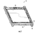
FIG. 2 is a schematic of a battery cell assembly utilized in the battery system ofFIG. 1 ; -
FIG. 3 is an exploded view of the battery cell assembly ofFIG. 2 ; -
FIG. 4 is an exploded view of a portion of the battery cell assembly ofFIG. 3 ; -
FIG. 5 is an exploded view of a cooling fin utilized in the battery cell assembly ofFIG. 4 ; -
FIG. 6 is a cross-sectional view of a portion of the cooling fin ofFIG. 4 ; -
FIG. 7 is a cross-sectional view of another portion of the cooling fin ofFIG. 4 ; and -
FIG. 8 is a flowchart of a method for cooling the battery cell assembly ofFIG. 2 in accordance with another exemplary embodiment. - Referring to
FIGS. 1-7 , abattery system 10 for generating electrical power in accordance with an exemplary embodiment is illustrated. Thebattery system 10 includes acompressor 22, acondenser 23, anexpansion valve 24, abattery cell assembly 26,conduits temperature sensor 60, acondenser fan 70, and amicroprocessor 80. An advantage of thebattery system 10 is that thesystem 10 utilizes acooling fin 140 disposed between adjacent battery cells that transitions a two-phase refrigerant to a gaseous refrigerant to cool the battery cells as will be explained in greater detail below. - For purposes of understanding, the term "refrigerant" corresponds to a substance that can reversibly transition between a liquid and a gas in a heat cycle. Exemplary refrigerants include R-11, R-12, R-122, R-134A, R-1407C and R-410A. Also, the term "gaseous refrigerant" corresponds to a refrigerant having primarily a gaseous state. Further, the term "liquid refrigerant" corresponds to a refrigerant having primarily a liquid state. Also, the term "two-phase refrigerant" corresponds to a refrigerant having a portion thereof in a liquid state and a remaining portion thereof in a gaseous state.
- The
compressor 22 is configured to pump and compress agaseous refrigerant 91 through theconduit 51 into thecondenser 23 in response to a control signal from themicroprocessor 80. As shown, theconduit 51 is fluidly coupled between thecompressor 22 and thecondenser 23. - The
condenser 23 is provided to receive thegaseous refrigerant 91 from thecompressor 22 via theconduit 51 and to transition thegaseous refrigerant 91 into aliquid refrigerant 92 by extracting heat energy from thegaseous refrigerant 91. As shown, theconduit 52 is fluidly coupled between thecondenser 23 and theexpansion valve 24. After exiting thecondenser 23, theliquid refrigerant 92 is further pumped through theconduit 52 to theexpansion valve 24. - The
expansion valve 24 is fluidly coupled between thecondenser 23 and thebattery cell assembly 26 via theconduits expansion valve 24 is configured to receive theliquid refrigerant 92 from thecondenser 23 and to decrease a pressure level of theliquid refrigerant 92 to obtain a two-phase refrigerant 93. The two-phase refrigerant 93 is routed from theexpansion valve 24 to theconduit 182 of thebattery cell assembly 26 via theconduit 53. - Referring to
FIGS. 2-7 , thebattery cell assembly 26 in accordance with an exemplary embodiment is provided. Thebattery cell assembly 26 includes rectangular ring-shaped frame members battery cells cooling fin 140. An advantage of thebattery cell assembly 26 is that theassembly 26 utilizes thecooling fin 140 disposed betweenadjacent battery cells liquid refrigerant 92 into thegaseous refrigerant 93 to cool thebattery cells - The rectangular ring-
shaped frame members battery cells shaped frame members shaped frame members - The
battery cells battery cells battery cells - The
battery cell 130 includes a rectangular-shaped pouch 150 andelectrodes pouch 150. Thebattery cell 130 is disposed between the rectangular ring-shaped frame member 120 and thecooling fin 140. - The
battery cell 132 includes a rectangular-shaped pouch 160, anelectrode 162 and another electrode (not shown). Thebattery cell 132 is disposed between the rectangular ring-shaped frame member 122 and thecooling fin 140. - Referring to
FIGS. 2-7 , thecooling fin 140 is provided to transfer heat energy from thebattery cells phase refrigerant 93 flowing through thecooling fin 140 to transition the two-phase refrigerant 93 into thegaseous refrigerant 91 within thecooling fin 140 to cool thebattery cells fin 140 includes a generally rectangular-shapedaluminum plate 180 and a tube 112. - The rectangular-shaped
aluminum plate 180 has afirst side 190 and asecond side 192. Theplate 180 further includes first, second, third, and fourthperipheral edge portions FIG. 5 ) that are each arcuate-shaped to hold a portion of thetube 182 thereon. In other words, the first, second, third, and fourthperipheral edge portions FIG. 6 ) configured to receive thetube 182 thereon. Thefirst side 190 is sized to cover substantially all of a generally rectangular-shaped side surface of thebattery cell 130. Thesecond side 192 is sized to cover substantially all of a generally rectangular-shaped side surface of thebattery cell 132. - The
tube 182 is coupled to thefirst side 190 of the generally rectangular-shapedaluminum plate 180, and is coupled to and extends on the first, second, third, and fourthperipheral edge portions plate 180. In one exemplary embodiment, thetube 182 is constructed of aluminum. However, thetube 182 could be constructed of other materials known to those skilled in the art. Referring toFIG. 5 , thetube 182 includes aninlet port 220,tube portions outlet port 232. Theinlet port 220 is coupled to thetube portion 222, and is further coupled to theconduit 53. Thetube portion 222 is coupled between theinlet port 220 and thetube portion 224. Thetube portion 226 is coupled between thetube portion 224 and thetube portion 228. Thetube portion 230 is coupled between thetube portion 228 and theoutlet port 232. Theoutlet port 232 is further coupled to theconduit 50. - Also, referring to
FIG. 5 , thetube portion 222 is coupled to the fourthperipheral edge portion 206, and thetube portion 224 is coupled to the firstperipheral edge portion 200, via brazing. Thetube portion 226 is coupled to the secondperipheral edge portion 202, and thetube portion 228 is coupled to the thirdperipheral edge portion 204, via brazing. Also, thetube portion 230 is coupled to the fourthperipheral edge portion 206 via brazing. - Referring to
FIGS. 3-5 , during operation, the two-phase refrigerant 93 enters theinlet port 220 from theconduit 53. While flowing through at least some of thetube portions gaseous refrigerant 91 and exits theoutlet port 232. Theoutlet port 232 is coupled to theconduit 50. In particular, heat energy generated by thebattery cell 130 is conducted through the rectangular-shapedaluminum plate 180 to thetube 182. Further, heat energy generated by thebattery cell 132 is conducted through the rectangular-shapedaluminum plate 180 to thetube 182. Further, the heat energy in thetube 182 is conducted into the two-phase refrigerant 93 flowing through the internal flow path within thetube 182 and transitions the two-phase refrigerant 93 into the gaseous refrigerant 91 to reduce a temperature of thebattery cell - Referring to
FIG. 1 , thetemperature sensor 60 is provided to generate a signal indicative of a temperature level of thebattery cells microprocessor 80. - The
condenser fan 70 is provided to blow air past thecondenser 23 to cool thecondenser 23 in response to a control signal from themicroprocessor 80. As shown, thecondenser fan 70 is disposed proximate to thecondenser 23. - The
microprocessor 80 is provided to control operation of thebattery system 10. In particular, themicroprocessor 80 is configured to generate control signals for controlling operation of thecompressor 22 and thecondenser fan 70 in response to a signal from thetemperature sensor 60. In particular, themicroprocessor 80 is configured to generate control signals to activate thecompressor 22 and thecondenser fan 70 if a temperature level of thebattery cells microprocessor 80 utilizes amemory device 81 that stores software instructions and associated data for controlling thecompressor 22 and thecondenser fan 70. Thus, themicroprocessor 80 is programmed to control thecompressor 22 and thecondenser fan 70 as described herein. - Referring to
FIGS. 1 ,3 ,5 and8 , a flowchart of a method for cooling thebattery cell assembly 26 in accordance with another exemplary embodiment will now be explained. - At
step 300, a user provides thebattery cell assembly 26 having thebattery cells fin 140 disposed between thebattery cells fin 140 has theinlet port 220, theoutlet port 232, and an internal flow path disposed between theinlet port 220 and theoutlet port 232. - At
step 302, the user provides thecompressor 22, thecondenser 23, and theexpansion valve 24. - At
step 304, theinlet port 220 of the coolingfin 140 receives the two-phase refrigerant 93 from theexpansion valve 24. - At
step 306, the coolingfin 140 receives heat energy from thebattery cells fin 140 and transitions the two-phase refrigerant 93 into thegaseous refrigerant 91 within the internal flow path of the coolingfin 140 utilizing the heat energy. - At
step 308, thecompressor 22 receives the gaseous refrigerant 91 from theoutlet port 232 of the coolingfin 140 and pumps the gaseous refrigerant 91 from thecompressor 22 to thecondenser 23. - At
step 310, thecondenser 23 receives the gaseous refrigerant 91 from thecompressor 22 and transitions the gaseous refrigerant 91 into the liquid refrigerant 92 by extracting heat energy from thegaseous refrigerant 91. - At
step 312, theexpansion valve 24 receives the liquid refrigerant 92 from thecondenser 23 and decreases a pressure level of the liquid refrigerant 92 to transition the liquid refrigerant 92 into the two-phase refrigerant 93. - At
step 314, theinlet port 220 of the coolingfin 140 receives the two-phase refrigerant 93 from theexpansion valve 24. - The
battery cell assembly 26 and the method for cooling battery cells provide a substantial advantage over other battery cell assemblies and methods. In particular, thebattery cell assembly 26 and the method provide a technical effect of utilizing a cooling fin disposed between adjacent battery cells that transitions a two-phase refrigerant into a gaseous refrigerant to effectively cool the battery cells. - While the claimed invention has been described in detail in connection with only a limited number of embodiments, it should be readily understood that the invention is not limited to such disclosed embodiments. Rather, the claimed invention can be modified to incorporate any number of variations, alterations, substitutions or equivalent arrangements not heretofore described, but which are commensurate with the spirit and scope of the invention. Additionally, while various embodiments of the claimed invention have been described, it is to be understood that aspects of the invention may include only some of the described embodiments. Accordingly, the claimed invention is not to be seen as limited by the foregoing description.
Claims (8)
- A battery system, comprising:a battery cell assembly having first and second battery cells and a cooling fin disposed between the first and second battery cells;the cooling fin having an inlet port, an outlet port, and an internal flow path disposed between the inlet port and the outlet port, the cooling fin configured to receive a two-phase refrigerant in the inlet port, the cooling fin further configured to receive heat energy from the first and second battery cells and to transition the two-phase refrigerant into a gaseous refrigerant within the internal flow path utilizing the heat energy;a compressor fluidly coupled to the outlet port and configured to pump the gaseous refrigerant into a condenser; andthe condenser fluidly coupled to the compressor and configured to receive the gaseous refrigerant from the compressor, the condenser further configured to transition the gaseous refrigerant into a liquid refrigerant by extracting heat energy from the gaseous refrigerant; andan expansion valve fluidly coupled between the condenser and the inlet port of the cooling fin, the expansion valve configured to receive the liquid refrigerant from the condenser and to decrease a pressure level of the liquid refrigerant to obtain the two-phase refrigerant, the two-phase refrigerant being routed from the expansion valve to the inlet port of the cooling fin.
- The battery system of claim 1, wherein the cooling fin has a generally rectangular-shaped plate and a tube; the generally rectangular-shaped plate having a first side and a second side; the tube coupled to the first side of the generally rectangular-shaped plate and extending on at least first, second, and third peripheral edge portions of the generally rectangular-shaped plate, the tube defining the internal flow path therein.
- The battery system of claim 2, wherein the generally rectangular-shaped plate is constructed of aluminum and the tube is constructed of aluminum.
- The battery system of claim 2, wherein the generally rectangular-shaped plate is sized to cover substantially all of a generally rectangular-shaped side surface of the first battery cell.
- The battery cell assembly of claim 2, wherein the first, second, and third peripheral edge portions of the generally rectangular-shaped aluminum plate define an arcuate-shaped groove configured to receive the tube thereon.
- The battery cell assembly of claim 1, wherein the tube is configured to transfer at least a portion of the heat energy to the two-phase refrigerant flowing in the tube.
- The battery cell assembly of claim 1, further comprising first and second rectangular ring-shaped frame members, the cooling fin and the first and second battery cells being disposed between the first and second rectangular ring-shaped frame members.
- A method for cooling a battery cell assembly, the battery cell assembly having first and second battery cells and a cooling fin disposed between the first and second battery cells, the cooling fin having an inlet port, an outlet port, and an internal flow path disposed between the inlet port and the outlet port, the method comprising:receiving a two-phase refrigerant in the inlet port of the cooling fin;receiving heat energy in the cooling fin from the first and second battery cells disposed on opposite sides of the cooling fin and transitioning the two-phase refrigerant into a gaseous refrigerant within the internal flow path of the cooling fin utilizing the heat energy;routing the gaseous refrigerant from the outlet port to a compressor;pumping the gaseous refrigerant from the compressor to a condenser utilizing the compressor;transitioning the gaseous refrigerant received by the condenser into a liquid refrigerant by extracting heat energy from the gaseous refrigerant utilizing the condenser;pumping the liquid refrigerant from the condenser to an expansion valve and decreasing a pressure level of the liquid refrigerant to obtain the two-phase refrigerant utilizing the expansion valve; androuting the two-phase refrigerant from the expansion valve to the inlet port of the cooling fin.
Applications Claiming Priority (2)
| Application Number | Priority Date | Filing Date | Title |
|---|---|---|---|
| US13/686,018 US9083066B2 (en) | 2012-11-27 | 2012-11-27 | Battery system and method for cooling a battery cell assembly |
| PCT/KR2013/010828 WO2014084589A1 (en) | 2012-11-27 | 2013-11-27 | Battery system and method for cooling battery cell assembly |
Publications (3)
| Publication Number | Publication Date |
|---|---|
| EP2928008A1 true EP2928008A1 (en) | 2015-10-07 |
| EP2928008A4 EP2928008A4 (en) | 2015-11-18 |
| EP2928008B1 EP2928008B1 (en) | 2017-01-11 |
Family
ID=50773567
Family Applications (1)
| Application Number | Title | Priority Date | Filing Date |
|---|---|---|---|
| EP13858793.6A Active EP2928008B1 (en) | 2012-11-27 | 2013-11-27 | Battery system and method for cooling battery cell assembly |
Country Status (6)
| Country | Link |
|---|---|
| US (1) | US9083066B2 (en) |
| EP (1) | EP2928008B1 (en) |
| JP (1) | JP6249495B2 (en) |
| KR (1) | KR101658582B1 (en) |
| CN (1) | CN105144465B (en) |
| WO (1) | WO2014084589A1 (en) |
Families Citing this family (28)
| Publication number | Priority date | Publication date | Assignee | Title |
|---|---|---|---|---|
| JP2823091B2 (en) | 1990-11-26 | 1998-11-11 | 本田技研工業株式会社 | Clutch release device |
| US9140501B2 (en) | 2008-06-30 | 2015-09-22 | Lg Chem, Ltd. | Battery module having a rubber cooling manifold |
| US9379420B2 (en) | 2012-03-29 | 2016-06-28 | Lg Chem, Ltd. | Battery system and method for cooling the battery system |
| US9605914B2 (en) | 2012-03-29 | 2017-03-28 | Lg Chem, Ltd. | Battery system and method of assembling the battery system |
| US9105950B2 (en) | 2012-03-29 | 2015-08-11 | Lg Chem, Ltd. | Battery system having an evaporative cooling member with a plate portion and a method for cooling the battery system |
| US8852781B2 (en) | 2012-05-19 | 2014-10-07 | Lg Chem, Ltd. | Battery cell assembly and method for manufacturing a cooling fin for the battery cell assembly |
| US9306199B2 (en) | 2012-08-16 | 2016-04-05 | Lg Chem, Ltd. | Battery module and method for assembling the battery module |
| US9083066B2 (en) | 2012-11-27 | 2015-07-14 | Lg Chem, Ltd. | Battery system and method for cooling a battery cell assembly |
| US8852783B2 (en) * | 2013-02-13 | 2014-10-07 | Lg Chem, Ltd. | Battery cell assembly and method for manufacturing the battery cell assembly |
| US9184424B2 (en) | 2013-07-08 | 2015-11-10 | Lg Chem, Ltd. | Battery assembly |
| US20150211805A1 (en) * | 2014-01-29 | 2015-07-30 | Kunshan Jue-Chung Electronics Co., Ltd. | Thermostat module |
| US9727896B2 (en) * | 2014-03-13 | 2017-08-08 | Johnnie E. Richardson | Systems, apparatus and methods facilitating mobile communications |
| US10770762B2 (en) | 2014-05-09 | 2020-09-08 | Lg Chem, Ltd. | Battery module and method of assembling the battery module |
| US10084218B2 (en) | 2014-05-09 | 2018-09-25 | Lg Chem, Ltd. | Battery pack and method of assembling the battery pack |
| US9484559B2 (en) | 2014-10-10 | 2016-11-01 | Lg Chem, Ltd. | Battery cell assembly |
| US9412980B2 (en) | 2014-10-17 | 2016-08-09 | Lg Chem, Ltd. | Battery cell assembly |
| US9786894B2 (en) | 2014-11-03 | 2017-10-10 | Lg Chem, Ltd. | Battery pack |
| US9627724B2 (en) | 2014-12-04 | 2017-04-18 | Lg Chem, Ltd. | Battery pack having a cooling plate assembly |
| US10263301B2 (en) | 2015-01-09 | 2019-04-16 | Dana Canada Corporation | Counter-flow heat exchanger for battery thermal management applications |
| CN107615567A (en) * | 2015-02-18 | 2018-01-19 | Ttb控股有限公司 | Li-ion battery module with cooling system |
| CA2982475A1 (en) * | 2015-04-21 | 2016-10-27 | Dana Canada Corporation | Counter-flow heat exchanger for battery thermal management applications |
| KR101991925B1 (en) | 2015-12-04 | 2019-06-21 | 주식회사 엘지화학 | Battery Module Comprising Cartridge Having Gripping Part |
| DE112017002349B4 (en) | 2016-05-06 | 2026-03-26 | Dana Canada Corporation | HEAT EXCHANGER |
| JP6670448B2 (en) * | 2016-08-16 | 2020-03-25 | 株式会社オートネットワーク技術研究所 | Power storage module |
| JP6978305B2 (en) * | 2017-12-25 | 2021-12-08 | 昭和電工株式会社 | Heat transfer device |
| KR102774863B1 (en) * | 2020-03-12 | 2025-03-04 | 주식회사 엘지에너지솔루션 | Easy assembling battery module and battery pack including the same |
| CA3080727A1 (en) * | 2020-05-13 | 2021-11-13 | Hydro-Quebec | Systeme de cyclage de cellules de batterie tout solide avec regulation de pression |
| CN113140854B (en) * | 2021-04-08 | 2022-05-13 | 大连理工大学 | A blade battery fixture with explosion-proof heat shield for two-phase immersion liquid cooling |
Family Cites Families (189)
| Publication number | Priority date | Publication date | Assignee | Title |
|---|---|---|---|---|
| DE436922C (en) | 1923-06-18 | 1926-11-11 | Fried Krupp Akt Ges Germaniawe | Cooling device for accumulator cells |
| US2391859A (en) | 1931-11-07 | 1946-01-01 | Hoover Co | Room cooling device |
| GB481891A (en) | 1936-09-18 | 1938-03-18 | India Rubber Gutta Percha Tele | Improvements in or relating to containers for electric storage cells |
| US2273244A (en) | 1940-04-03 | 1942-02-17 | Electric Storage Battery Co | Storage battery cell |
| SE319224B (en) | 1966-12-19 | 1970-01-12 | Asea Ab | |
| US3503558A (en) | 1968-03-14 | 1970-03-31 | Electrolux Corp | Exhaust diffusion manifold for a vacuum cleaner or the like |
| US3550681A (en) | 1968-12-30 | 1970-12-29 | Gen Motors Corp | Self-adjusting thermal connector |
| US4009752A (en) | 1975-02-24 | 1977-03-01 | Honeywell Information Systems Inc. | Warp-resistant heat sink |
| US3964930A (en) | 1975-07-21 | 1976-06-22 | United Technologies Corporation | Fuel cell cooling system |
| US4063590A (en) | 1976-10-22 | 1977-12-20 | Mcconnell Christopher L | Preheater for clothes dryer |
| US4305456A (en) | 1977-08-12 | 1981-12-15 | Paul Mueller Company | Condenser and hot water system |
| US4298904A (en) | 1979-12-17 | 1981-11-03 | The Boeing Company | Electronic conduction cooling clamp |
| US4322776A (en) | 1980-08-04 | 1982-03-30 | Hughes Aircraft Company | Thermal interconnection |
| US4444994A (en) | 1982-01-29 | 1984-04-24 | Varo, Inc. | Electrically insulated quick disconnect heat sink |
| US4518663A (en) | 1983-07-01 | 1985-05-21 | Energy Development Associates, Inc. | Electrolyte circulation subsystem |
| GB8329269D0 (en) | 1983-11-02 | 1983-12-07 | British Aerospace | Electronic apparatus stowage |
| US4777561A (en) | 1985-03-26 | 1988-10-11 | Hughes Aircraft Company | Electronic module with self-activated heat pipe |
| FR2580433B1 (en) | 1985-04-16 | 1987-08-14 | Socapex | THERMAL CONNECTOR FOR PRINTED CIRCUIT BOARD COATED WITH ELECTRONIC COMPONENTS |
| US4849858A (en) | 1986-10-20 | 1989-07-18 | Westinghouse Electric Corp. | Composite heat transfer means |
| US4995240A (en) | 1987-01-27 | 1991-02-26 | Eaton Corporation | Controlling refrigeration having control module directly attached on valve body |
| US5057968A (en) | 1989-10-16 | 1991-10-15 | Lockheed Corporation | Cooling system for electronic modules |
| US4982785A (en) | 1990-03-06 | 1991-01-08 | Inter-City Products Corporation (Usa) | Serpentine heat exchanger |
| US5186250A (en) | 1990-05-11 | 1993-02-16 | Showa Aluminum Kabushiki Kaisha | Tube for heat exchangers and a method for manufacturing the tube |
| CH679620A5 (en) | 1990-12-11 | 1992-03-13 | Sulzer Ag | |
| US5071652A (en) | 1990-12-11 | 1991-12-10 | Globe-Union Inc. | Metal oxide hydrogen battery having improved heat transfer properties |
| US5392873A (en) | 1992-01-22 | 1995-02-28 | Honda Giken Kogyo Kabushiki Kaisha | Structure for securing batteries used in an electric vehicle |
| US5214564A (en) | 1992-04-23 | 1993-05-25 | Sunstrand Corporation | Capacitor assembly with integral cooling apparatus |
| FR2697677B1 (en) | 1992-11-02 | 1994-12-30 | Europ Accumulateurs | Thermoregulated storage battery, especially for electric vehicles. |
| JP2903913B2 (en) | 1992-11-10 | 1999-06-14 | 松下電器産業株式会社 | Storage battery system |
| US5356735A (en) | 1993-05-10 | 1994-10-18 | General Motors Corporation | Heated/cooled battery |
| US5329988A (en) | 1993-05-28 | 1994-07-19 | The Allen Group, Inc. | Heat exchanger |
| US5520976A (en) | 1993-06-30 | 1996-05-28 | Simmonds Precision Products Inc. | Composite enclosure for electronic hardware |
| US5472802A (en) | 1993-10-25 | 1995-12-05 | Ovonic Battery Company, Inc. | Sealed hydride batteries, including a new lid-terminal seal and electrode tab collecting comb |
| US5663007A (en) | 1994-02-23 | 1997-09-02 | Matsushita Electric Industrial Co., Ltd. | Sealed storage battery and method for manufacturing the same |
| JP3260951B2 (en) | 1994-02-23 | 2002-02-25 | 松下電器産業株式会社 | Single cell and unit cell of sealed alkaline storage battery |
| US5346786A (en) | 1994-03-21 | 1994-09-13 | Hodgetts Philip J | Modular rack mounted battery system |
| JPH08111244A (en) | 1994-10-12 | 1996-04-30 | Nissan Motor Co Ltd | Stacked battery device |
| JP3451142B2 (en) | 1994-11-18 | 2003-09-29 | 本田技研工業株式会社 | Battery assembly with temperature control mechanism |
| JP3745424B2 (en) | 1995-11-06 | 2006-02-15 | 東芝電池株式会社 | Battery manufacturing method |
| JPH09219213A (en) | 1996-02-09 | 1997-08-19 | Nissan Motor Co Ltd | Secondary battery for electric vehicle and its temperature rise alleviation device |
| JP3225192B2 (en) | 1996-04-10 | 2001-11-05 | 本田技研工業株式会社 | Battery exhaust gas control system |
| JP3240973B2 (en) | 1997-03-05 | 2001-12-25 | トヨタ自動車株式会社 | Battery cooling system for vehicles |
| EP1030389B1 (en) | 1997-03-24 | 2003-01-08 | Matsushita Electric Industrial Co., Ltd. | Battery housing with integrated cables for voltage measuring |
| US6087036A (en) | 1997-07-25 | 2000-07-11 | 3M Innovative Properties Company | Thermal management system and method for a solid-state energy storing device |
| JP3830243B2 (en) | 1997-10-06 | 2006-10-04 | トヨタ自動車株式会社 | Battery power supply |
| JP3790946B2 (en) | 1997-12-08 | 2006-06-28 | 株式会社ヴァレオサーマルシステムズ | Heat exchanger |
| FR2774215B1 (en) | 1998-01-29 | 2000-02-25 | Alsthom Cge Alcatel | WATERPROOF MONOBLOCK BATTERY PROVIDED WITH A COOLING DEVICE |
| EP0948065B1 (en) | 1998-03-30 | 2003-06-04 | Renata AG | Safety vent for accumulator or battery |
| JPH11307139A (en) * | 1998-04-23 | 1999-11-05 | Nippon Soken Inc | Battery cooling device |
| US6255015B1 (en) | 1998-08-23 | 2001-07-03 | Ovonic Battery Company, Inc. | Monoblock battery assembly |
| JP4231127B2 (en) | 1998-09-03 | 2009-02-25 | パナソニック株式会社 | Integrated battery temperature control method and apparatus |
| US6176095B1 (en) | 1999-01-19 | 2001-01-23 | Carrier Corporation | Pretrip device for testing of a refrigeration system compressor |
| JP5025039B2 (en) * | 1999-07-07 | 2012-09-12 | 株式会社日本自動車部品総合研究所 | Battery temperature control device |
| JP4778602B2 (en) | 1999-07-22 | 2011-09-21 | パナソニック株式会社 | Secondary battery |
| JP4416266B2 (en) | 1999-10-08 | 2010-02-17 | パナソニック株式会社 | Sealed prismatic battery |
| JP4252172B2 (en) | 1999-10-12 | 2009-04-08 | 株式会社日本自動車部品総合研究所 | Battery cooling system |
| US6399238B1 (en) | 1999-12-13 | 2002-06-04 | Alcatel | Module configuration |
| JP3777981B2 (en) | 2000-04-13 | 2006-05-24 | トヨタ自動車株式会社 | Vehicle power supply |
| DE10021161A1 (en) | 2000-04-29 | 2001-10-31 | Vb Autobatterie Gmbh | Method for determining the state of charge and the load capacity of an electric accumulator |
| JP4116238B2 (en) | 2000-05-19 | 2008-07-09 | 株式会社タイカ | Thermally conductive sheet having electromagnetic shielding properties |
| US6462949B1 (en) | 2000-08-07 | 2002-10-08 | Thermotek, Inc. | Electronic enclosure cooling system |
| JP3727840B2 (en) | 2000-09-29 | 2005-12-21 | 株式会社東芝 | Battery pack and portable electronic device |
| JP3576092B2 (en) | 2000-11-10 | 2004-10-13 | 松下冷機株式会社 | refrigerator |
| FR2819036B1 (en) | 2001-01-04 | 2004-01-16 | Cit Alcatel | VALVE AND ELECTROCHEMICAL GENERATOR COMPRISING SUCH A VALVE |
| US6569556B2 (en) | 2001-01-29 | 2003-05-27 | General Motors Corporation | Cooling system for a battery pack |
| JP4892788B2 (en) | 2001-04-23 | 2012-03-07 | トヨタ自動車株式会社 | Battery module |
| US6422027B1 (en) | 2001-05-03 | 2002-07-23 | Ford Global Tech., Inc. | System and method for cooling a battery pack |
| JP2002352866A (en) * | 2001-05-28 | 2002-12-06 | Honda Motor Co Ltd | Electric vehicle battery cooling system |
| JP4361229B2 (en) | 2001-07-04 | 2009-11-11 | 日産自動車株式会社 | Battery system |
| US6512347B1 (en) | 2001-10-18 | 2003-01-28 | General Motors Corporation | Battery having an integral cooling system |
| JP3969254B2 (en) | 2001-10-29 | 2007-09-05 | 株式会社デンソー | Battery temperature management device |
| JP2003188323A (en) | 2001-12-19 | 2003-07-04 | Sony Corp | Graphite sheet and method for producing the same |
| JP2005513403A (en) | 2001-12-21 | 2005-05-12 | ベール ゲーエムベーハー ウント コー カーゲー | Especially heat exchanger for automobile |
| KR20040082437A (en) | 2002-02-19 | 2004-09-24 | 쓰리엠 이노베이티브 프로퍼티즈 컴파니 | Temperature control apparatus and method for high energy electrochemical cells |
| US6821671B2 (en) | 2002-03-01 | 2004-11-23 | Lg Chem, Ltd. | Method and apparatus for cooling and positioning prismatic battery cells |
| JP2003282112A (en) | 2002-03-26 | 2003-10-03 | Denso Corp | Intermediate heat exchanger for fuel cells |
| JP3733079B2 (en) | 2002-03-29 | 2006-01-11 | 三洋電機株式会社 | Cold storage |
| JP4041334B2 (en) * | 2002-04-08 | 2008-01-30 | 株式会社不二工機 | Expansion valve and refrigeration cycle |
| US6889762B2 (en) | 2002-04-29 | 2005-05-10 | Bergstrom, Inc. | Vehicle air conditioning and heating system providing engine on and engine off operation |
| JP4242665B2 (en) | 2002-05-13 | 2009-03-25 | パナソニック株式会社 | Battery pack cooling device and secondary battery |
| KR100474909B1 (en) * | 2002-06-12 | 2005-03-08 | 엘지전자 주식회사 | heating and cooling system |
| KR100471233B1 (en) | 2002-06-26 | 2005-03-10 | 현대자동차주식회사 | Method of generating maximum charge current and maximum discharge current for battery in a hybrid electric vehicle |
| CA2392610C (en) | 2002-07-05 | 2010-11-02 | Long Manufacturing Ltd. | Baffled surface cooled heat exchanger |
| US7010644B2 (en) | 2002-08-29 | 2006-03-07 | Micron Technology, Inc. | Software refreshed memory device and method |
| US7143124B2 (en) | 2002-12-06 | 2006-11-28 | Sun Microsystems, Inc. | Detection of dead regions during incremental collection |
| US7070874B2 (en) | 2002-12-24 | 2006-07-04 | Fuelcell Energy, Inc. | Fuel cell end unit with integrated heat exchanger |
| JP3867060B2 (en) | 2003-03-28 | 2007-01-10 | 三菱電機株式会社 | Vehicle power supply system |
| JP2004333115A (en) | 2003-04-16 | 2004-11-25 | Showa Denko Kk | Heat exchanger and method of manufacturing the same |
| US20050026014A1 (en) | 2003-07-31 | 2005-02-03 | Michael Fogaing | Polymer batteries having thermal exchange apparatus |
| JP4045340B2 (en) | 2003-08-13 | 2008-02-13 | 現代自動車株式会社 | Battery effective power calculation method and calculation system |
| JP4578867B2 (en) | 2003-09-30 | 2010-11-10 | 株式会社日立製作所 | Hydrogen storage / supply device and system thereof, distributed power source using the same, and automobile |
| US7270910B2 (en) | 2003-10-03 | 2007-09-18 | Black & Decker Inc. | Thermal management systems for battery packs |
| US6826948B1 (en) | 2003-10-09 | 2004-12-07 | Delphi Technologies, Inc. | Leak detection apparatus for a liquid circulation cooling system |
| JP4078553B2 (en) | 2003-10-21 | 2008-04-23 | 新神戸電機株式会社 | Lithium battery module for vehicles |
| JP2005147443A (en) | 2003-11-12 | 2005-06-09 | Calsonic Kansei Corp | Laminated type heat exchanger |
| WO2005059427A1 (en) | 2003-12-17 | 2005-06-30 | Eaton Corporation | Fitting for fluid conveyance |
| US7237395B2 (en) | 2003-12-22 | 2007-07-03 | General Electric Company | Methods and apparatus for controlling refrigerators |
| KR100799866B1 (en) | 2004-03-16 | 2008-01-31 | 주식회사 엘지화학 | Secondary battery with excellent safety |
| JP2005349955A (en) | 2004-06-10 | 2005-12-22 | Toyota Motor Corp | Cooling structure of power storage mechanism |
| CA2583168C (en) | 2004-10-05 | 2013-01-29 | Nitto Denko Corporation | Fuel cell and power generating method |
| JP2006139928A (en) | 2004-11-10 | 2006-06-01 | Nissan Motor Co Ltd | Battery system |
| KR100637472B1 (en) | 2004-12-07 | 2006-10-23 | 삼성에스디아이 주식회사 | Secondary battery module |
| KR100876458B1 (en) | 2004-12-24 | 2008-12-29 | 주식회사 엘지화학 | Battery cartridge of novel structure and open battery module containing it |
| KR100667943B1 (en) * | 2005-01-26 | 2007-01-11 | 삼성에스디아이 주식회사 | Secondary battery module |
| MX2007011126A (en) | 2005-03-16 | 2007-11-13 | Ford Global Tech Llc | Power supply system. |
| KR20060102853A (en) | 2005-03-25 | 2006-09-28 | 삼성에스디아이 주식회사 | Secondary battery module |
| US9653748B2 (en) | 2005-04-14 | 2017-05-16 | Enerdel, Inc. | Apparatus and method for securing battery cell packs |
| US7278389B2 (en) | 2005-04-19 | 2007-10-09 | Murat Kirakosyan | Automobile intake air flow plenum and plenum diverter |
| KR100880386B1 (en) | 2005-06-03 | 2009-01-23 | 주식회사 엘지화학 | Secondary battery of novel structure and battery pack including same |
| KR100765659B1 (en) | 2005-08-09 | 2007-10-10 | 현대자동차주식회사 | Fuel cell stack structure for automobile |
| JP2007048750A (en) | 2005-08-10 | 2007-02-22 | Samsung Sdi Co Ltd | Battery module |
| JP4600212B2 (en) | 2005-08-23 | 2010-12-15 | 株式会社デンソー | Supercritical refrigeration cycle equipment |
| US7658224B2 (en) | 2005-09-19 | 2010-02-09 | Dana Canada Corporation | Flanged connection for heat exchanger |
| US20070087266A1 (en) | 2005-10-18 | 2007-04-19 | Debbi Bourke | Modular battery system |
| US8030886B2 (en) | 2005-12-21 | 2011-10-04 | Nuventix, Inc. | Thermal management of batteries using synthetic jets |
| DE102006015568B3 (en) | 2006-04-04 | 2007-05-31 | Daimlerchrysler Ag | Process for the production of a heat exchanger module for heat exchangers for electrochemical energy storage, and device for carrying out the process |
| JP4857896B2 (en) | 2006-05-11 | 2012-01-18 | トヨタ自動車株式会社 | Battery pack and vehicle |
| DE102007028252B4 (en) | 2006-06-26 | 2017-02-02 | Denso Corporation | Refrigerant cycle device with ejector |
| JP2008054379A (en) | 2006-08-22 | 2008-03-06 | Calsonic Kansei Corp | Battery cooling system for vehicle |
| JP4251204B2 (en) | 2006-08-31 | 2009-04-08 | 日産自動車株式会社 | Battery module |
| JP2008062875A (en) | 2006-09-11 | 2008-03-21 | Calsonic Kansei Corp | Battery cooling system for vehicle |
| KR100921346B1 (en) | 2006-09-25 | 2009-10-13 | 주식회사 엘지화학 | Medium and large battery module and battery module assembly |
| JP2008080995A (en) | 2006-09-28 | 2008-04-10 | Denso Corp | Cooling system |
| US7531270B2 (en) | 2006-10-13 | 2009-05-12 | Enerdel, Inc. | Battery pack with integral cooling and bussing devices |
| KR100889241B1 (en) | 2006-10-23 | 2009-03-17 | 주식회사 엘지화학 | Electrode terminal connection member of battery module |
| US7797958B2 (en) | 2006-11-15 | 2010-09-21 | Glacier Bay, Inc. | HVAC system controlled by a battery management system |
| KR101064240B1 (en) | 2006-11-27 | 2011-09-14 | 주식회사 엘지화학 | Power system with thermal radiation protection |
| JP2008159440A (en) | 2006-12-25 | 2008-07-10 | Calsonic Kansei Corp | Vehicular battery cooling system |
| US8268505B2 (en) | 2007-01-25 | 2012-09-18 | Honda Motor Co., Ltd. | Fuel cell system |
| DE102007004567A1 (en) | 2007-01-30 | 2008-07-31 | Robert Bosch Gmbh | Electrochemical cell e.g. coffee-bag cell, housing device for traction system of e.g. hybrid motor vehicle, has cell and lugs for contacting, where cell is enclosed between housing parts, which clamp cell between parts using pressing force |
| WO2008111162A1 (en) | 2007-03-13 | 2008-09-18 | Hoshizaki Denki Kabushiki Kaisha | Cooling storage chamber and method for operating the same |
| KR100942985B1 (en) | 2007-03-21 | 2010-02-17 | 주식회사 엘지화학 | Medium and large battery pack case with improved distribution uniformity of refrigerant flow rate |
| KR101212362B1 (en) | 2007-04-04 | 2012-12-13 | 에스케이이노베이션 주식회사 | Temperature controller for electric vehicle using thermoelectric semiconductor |
| JP5236210B2 (en) | 2007-05-10 | 2013-07-17 | カルソニックカンセイ株式会社 | Battery module structure of the battery |
| US7846573B2 (en) | 2007-06-01 | 2010-12-07 | Cobasys, Llc | Coolant manifold |
| JP4438830B2 (en) | 2007-06-19 | 2010-03-24 | コニカミノルタビジネステクノロジーズ株式会社 | Resin composition, molded body, electrophotographic transfer belt, and image forming apparatus |
| JP5142605B2 (en) * | 2007-06-28 | 2013-02-13 | 三洋電機株式会社 | Power supply for vehicle |
| JP5137480B2 (en) | 2007-06-29 | 2013-02-06 | 三洋電機株式会社 | Power supply for vehicle |
| JP2009054297A (en) | 2007-08-23 | 2009-03-12 | Toshiba Corp | Battery pack |
| DE102007045183A1 (en) | 2007-09-21 | 2009-04-02 | Robert Bosch Gmbh | Temperierte battery device and method for this purpose |
| KR100872225B1 (en) | 2007-11-05 | 2008-12-05 | 엘지전자 주식회사 | Refrigerator Control Method |
| WO2009061451A1 (en) | 2007-11-07 | 2009-05-14 | Enerdel, Inc. | Battery assembly with temperature control device |
| US9283826B2 (en) | 2007-11-13 | 2016-03-15 | Mahle International Gmbh | Device for cooling a heat source of a motor vehicle |
| US8409743B2 (en) | 2007-11-28 | 2013-04-02 | Sanyo Electric Co., Ltd. | Battery system with battery cells arranged in array alignment |
| US8628872B2 (en) | 2008-01-18 | 2014-01-14 | Lg Chem, Ltd. | Battery cell assembly and method for assembling the battery cell assembly |
| DE102008011466A1 (en) | 2008-02-27 | 2009-09-03 | Robert Bosch Gmbh | battery module |
| CN101978549A (en) | 2008-03-24 | 2011-02-16 | 三洋电机株式会社 | Battery device and battery unit |
| KR20090107443A (en) | 2008-04-08 | 2009-10-13 | 쏘씨에떼 드 베이뀔르 엘렉트리끄 | An electric battery comprising a flexible power generation element and a mechanical and thermal control system of the power generation elements |
| US7851080B2 (en) | 2008-04-09 | 2010-12-14 | Gm Global Technology Operations, Inc. | Battery cooling plate design with discrete channels |
| US8465863B2 (en) | 2008-04-09 | 2013-06-18 | GM Global Technology Operations LLC | Batteries and components thereof and methods of making and assembling the same |
| JP2009252646A (en) * | 2008-04-09 | 2009-10-29 | Calsonic Kansei Corp | Cooling device of heat generator |
| US8215432B2 (en) | 2008-05-09 | 2012-07-10 | GM Global Technology Operations LLC | Battery thermal system for vehicle |
| US8486552B2 (en) | 2008-06-30 | 2013-07-16 | Lg Chem, Ltd. | Battery module having cooling manifold with ported screws and method for cooling the battery module |
| US9759495B2 (en) | 2008-06-30 | 2017-09-12 | Lg Chem, Ltd. | Battery cell assembly having heat exchanger with serpentine flow path |
| US8426050B2 (en) | 2008-06-30 | 2013-04-23 | Lg Chem, Ltd. | Battery module having cooling manifold and method for cooling battery module |
| US8067111B2 (en) | 2008-06-30 | 2011-11-29 | Lg Chem, Ltd. | Battery module having battery cell assembly with heat exchanger |
| US7883793B2 (en) | 2008-06-30 | 2011-02-08 | Lg Chem, Ltd. | Battery module having battery cell assemblies with alignment-coupling features |
| US9140501B2 (en) | 2008-06-30 | 2015-09-22 | Lg Chem, Ltd. | Battery module having a rubber cooling manifold |
| EP2634028B1 (en) | 2009-03-30 | 2017-01-11 | MAHLE Behr GmbH & Co. KG | Device for the thermal connection of an energy storage device |
| US8852778B2 (en) | 2009-04-30 | 2014-10-07 | Lg Chem, Ltd. | Battery systems, battery modules, and method for cooling a battery module |
| US8663829B2 (en) | 2009-04-30 | 2014-03-04 | Lg Chem, Ltd. | Battery systems, battery modules, and method for cooling a battery module |
| US20100275619A1 (en) | 2009-04-30 | 2010-11-04 | Lg Chem, Ltd. | Cooling system for a battery system and a method for cooling the battery system |
| US8403030B2 (en) | 2009-04-30 | 2013-03-26 | Lg Chem, Ltd. | Cooling manifold |
| ITBO20090427A1 (en) | 2009-07-02 | 2011-01-03 | Ferrari Spa | ELECTRIC TRACTION VEHICLE WITH COOLING THROUGH REFRIGERATED CYCLE |
| US8399118B2 (en) | 2009-07-29 | 2013-03-19 | Lg Chem, Ltd. | Battery module and method for cooling the battery module |
| US8703318B2 (en) | 2009-07-29 | 2014-04-22 | Lg Chem, Ltd. | Battery module and method for cooling the battery module |
| US8399119B2 (en) * | 2009-08-28 | 2013-03-19 | Lg Chem, Ltd. | Battery module and method for cooling the battery module |
| KR20110024954A (en) | 2009-09-03 | 2011-03-09 | 삼성전자주식회사 | Secondary Battery Module with Cooling Channel |
| JP2011093338A (en) * | 2009-10-27 | 2011-05-12 | Sumitomo Electric Ind Ltd | Warming-up device for automobile and method of warming up automobile |
| KR101093959B1 (en) | 2010-02-04 | 2011-12-15 | 에스비리모티브 주식회사 | Heat sink in battery module |
| KR101205180B1 (en) | 2010-05-18 | 2012-11-27 | 주식회사 엘지화학 | Cooling Member of Compact Structure and Excellent Stability and Battery Module Employed with the Same |
| US8460815B2 (en) | 2010-05-28 | 2013-06-11 | GM Global Technology Operations LLC | Stackable repeating frame with integrated cell sensing connection |
| US9065158B2 (en) | 2010-05-28 | 2015-06-23 | GM Global Technology Operations LLC | Corrugated fin and frame assembly for battery cooling |
| JP5625115B2 (en) * | 2010-08-16 | 2014-11-12 | エルジー・ケム・リミテッド | A small-sized battery module having excellent heat radiation characteristics, and a medium- or large-sized battery pack using the battery module |
| JP5978214B2 (en) * | 2010-09-02 | 2016-08-24 | アカソル・ゲゼルシャフト・ミット・ベシュレンクテル・ハフツング | Cooling module and method for manufacturing cooling module |
| US8662153B2 (en) | 2010-10-04 | 2014-03-04 | Lg Chem, Ltd. | Battery cell assembly, heat exchanger, and method for manufacturing the heat exchanger |
| KR20120050640A (en) * | 2010-11-11 | 2012-05-21 | 현대모비스 주식회사 | Battery thermal management system |
| CN103283063B (en) * | 2010-12-28 | 2016-02-24 | 株式会社Lg化学 | Battery module receiving device, battery module thermostat, and power storage system including the same |
| CN202217748U (en) * | 2011-07-05 | 2012-05-09 | 惠州比亚迪电池有限公司 | Battery heat abstractor and group battery |
| JP5768683B2 (en) | 2011-11-28 | 2015-08-26 | 富士通株式会社 | Reception data processing method, communication apparatus, and program |
| US9105950B2 (en) | 2012-03-29 | 2015-08-11 | Lg Chem, Ltd. | Battery system having an evaporative cooling member with a plate portion and a method for cooling the battery system |
| US8852781B2 (en) | 2012-05-19 | 2014-10-07 | Lg Chem, Ltd. | Battery cell assembly and method for manufacturing a cooling fin for the battery cell assembly |
| US9306199B2 (en) | 2012-08-16 | 2016-04-05 | Lg Chem, Ltd. | Battery module and method for assembling the battery module |
| US9960395B2 (en) | 2012-08-16 | 2018-05-01 | Lg Chem, Ltd. | Battery module |
| US20140120390A1 (en) | 2012-10-31 | 2014-05-01 | Lg Chem, Ltd. | Battery cell assembly and method for manufacturing a cooling fin for the battery cell assembly |
| US9083066B2 (en) | 2012-11-27 | 2015-07-14 | Lg Chem, Ltd. | Battery system and method for cooling a battery cell assembly |
| US8852783B2 (en) | 2013-02-13 | 2014-10-07 | Lg Chem, Ltd. | Battery cell assembly and method for manufacturing the battery cell assembly |
| US9647292B2 (en) | 2013-04-12 | 2017-05-09 | Lg Chem, Ltd. | Battery cell assembly and method for manufacturing a cooling fin for the battery cell assembly |
| US9184424B2 (en) | 2013-07-08 | 2015-11-10 | Lg Chem, Ltd. | Battery assembly |
-
2012
- 2012-11-27 US US13/686,018 patent/US9083066B2/en active Active
-
2013
- 2013-11-27 WO PCT/KR2013/010828 patent/WO2014084589A1/en not_active Ceased
- 2013-11-27 KR KR1020157011020A patent/KR101658582B1/en active Active
- 2013-11-27 JP JP2015542968A patent/JP6249495B2/en active Active
- 2013-11-27 CN CN201380059796.1A patent/CN105144465B/en active Active
- 2013-11-27 EP EP13858793.6A patent/EP2928008B1/en active Active
Also Published As
| Publication number | Publication date |
|---|---|
| EP2928008A4 (en) | 2015-11-18 |
| JP2016502234A (en) | 2016-01-21 |
| KR20150073181A (en) | 2015-06-30 |
| KR101658582B1 (en) | 2016-09-21 |
| JP6249495B2 (en) | 2017-12-20 |
| CN105144465A (en) | 2015-12-09 |
| CN105144465B (en) | 2017-10-20 |
| WO2014084589A1 (en) | 2014-06-05 |
| EP2928008B1 (en) | 2017-01-11 |
| US9083066B2 (en) | 2015-07-14 |
| US20140147709A1 (en) | 2014-05-29 |
Similar Documents
| Publication | Publication Date | Title |
|---|---|---|
| EP2928008B1 (en) | Battery system and method for cooling battery cell assembly | |
| US8399119B2 (en) | Battery module and method for cooling the battery module | |
| US8663828B2 (en) | Battery systems, battery module, and method for cooling the battery module | |
| US9105950B2 (en) | Battery system having an evaporative cooling member with a plate portion and a method for cooling the battery system | |
| US8399118B2 (en) | Battery module and method for cooling the battery module | |
| US8403030B2 (en) | Cooling manifold | |
| US8852778B2 (en) | Battery systems, battery modules, and method for cooling a battery module | |
| US9379420B2 (en) | Battery system and method for cooling the battery system | |
| EP2965932A1 (en) | Vehicle air conditioning device | |
| CN103807175B (en) | Dual-rotor two-stage enthalpy-increasing compressor, air conditioner and heat pump water heater | |
| ATE439559T1 (en) | SECOND TEMPERATURE REFRIGERANT CIRCUIT | |
| JP7356006B2 (en) | Refrigeration equipment |
Legal Events
| Date | Code | Title | Description |
|---|---|---|---|
| PUAI | Public reference made under article 153(3) epc to a published international application that has entered the european phase |
Free format text: ORIGINAL CODE: 0009012 |
|
| 17P | Request for examination filed |
Effective date: 20150513 |
|
| AK | Designated contracting states |
Kind code of ref document: A1 Designated state(s): AL AT BE BG CH CY CZ DE DK EE ES FI FR GB GR HR HU IE IS IT LI LT LU LV MC MK MT NL NO PL PT RO RS SE SI SK SM TR |
|
| AX | Request for extension of the european patent |
Extension state: BA ME |
|
| RIC1 | Information provided on ipc code assigned before grant |
Ipc: H01M 10/60 20140101AFI20151008BHEP Ipc: H01M 10/04 20060101ALI20151008BHEP |
|
| RA4 | Supplementary search report drawn up and despatched (corrected) |
Effective date: 20151016 |
|
| DAX | Request for extension of the european patent (deleted) | ||
| GRAP | Despatch of communication of intention to grant a patent |
Free format text: ORIGINAL CODE: EPIDOSNIGR1 |
|
| INTG | Intention to grant announced |
Effective date: 20160928 |
|
| GRAS | Grant fee paid |
Free format text: ORIGINAL CODE: EPIDOSNIGR3 |
|
| STAA | Information on the status of an ep patent application or granted ep patent |
Free format text: STATUS: GRANT OF PATENT IS INTENDED |
|
| GRAA | (expected) grant |
Free format text: ORIGINAL CODE: 0009210 |
|
| STAA | Information on the status of an ep patent application or granted ep patent |
Free format text: STATUS: THE PATENT HAS BEEN GRANTED |
|
| AK | Designated contracting states |
Kind code of ref document: B1 Designated state(s): AL AT BE BG CH CY CZ DE DK EE ES FI FR GB GR HR HU IE IS IT LI LT LU LV MC MK MT NL NO PL PT RO RS SE SI SK SM TR |
|
| REG | Reference to a national code |
Ref country code: GB Ref legal event code: FG4D |
|
| REG | Reference to a national code |
Ref country code: CH Ref legal event code: EP |
|
| REG | Reference to a national code |
Ref country code: AT Ref legal event code: REF Ref document number: 862046 Country of ref document: AT Kind code of ref document: T Effective date: 20170115 |
|
| REG | Reference to a national code |
Ref country code: IE Ref legal event code: FG4D |
|
| REG | Reference to a national code |
Ref country code: DE Ref legal event code: R096 Ref document number: 602013016624 Country of ref document: DE |
|
| REG | Reference to a national code |
Ref country code: LT Ref legal event code: MG4D |
|
| REG | Reference to a national code |
Ref country code: NL Ref legal event code: MP Effective date: 20170111 |
|
| REG | Reference to a national code |
Ref country code: AT Ref legal event code: MK05 Ref document number: 862046 Country of ref document: AT Kind code of ref document: T Effective date: 20170111 |
|
| PG25 | Lapsed in a contracting state [announced via postgrant information from national office to epo] |
Ref country code: NL Free format text: LAPSE BECAUSE OF FAILURE TO SUBMIT A TRANSLATION OF THE DESCRIPTION OR TO PAY THE FEE WITHIN THE PRESCRIBED TIME-LIMIT Effective date: 20170111 |
|
| PG25 | Lapsed in a contracting state [announced via postgrant information from national office to epo] |
Ref country code: LT Free format text: LAPSE BECAUSE OF FAILURE TO SUBMIT A TRANSLATION OF THE DESCRIPTION OR TO PAY THE FEE WITHIN THE PRESCRIBED TIME-LIMIT Effective date: 20170111 Ref country code: GR Free format text: LAPSE BECAUSE OF FAILURE TO SUBMIT A TRANSLATION OF THE DESCRIPTION OR TO PAY THE FEE WITHIN THE PRESCRIBED TIME-LIMIT Effective date: 20170412 Ref country code: IS Free format text: LAPSE BECAUSE OF FAILURE TO SUBMIT A TRANSLATION OF THE DESCRIPTION OR TO PAY THE FEE WITHIN THE PRESCRIBED TIME-LIMIT Effective date: 20170511 Ref country code: HR Free format text: LAPSE BECAUSE OF FAILURE TO SUBMIT A TRANSLATION OF THE DESCRIPTION OR TO PAY THE FEE WITHIN THE PRESCRIBED TIME-LIMIT Effective date: 20170111 Ref country code: FI Free format text: LAPSE BECAUSE OF FAILURE TO SUBMIT A TRANSLATION OF THE DESCRIPTION OR TO PAY THE FEE WITHIN THE PRESCRIBED TIME-LIMIT Effective date: 20170111 Ref country code: NO Free format text: LAPSE BECAUSE OF FAILURE TO SUBMIT A TRANSLATION OF THE DESCRIPTION OR TO PAY THE FEE WITHIN THE PRESCRIBED TIME-LIMIT Effective date: 20170411 |
|
| PG25 | Lapsed in a contracting state [announced via postgrant information from national office to epo] |
Ref country code: PL Free format text: LAPSE BECAUSE OF FAILURE TO SUBMIT A TRANSLATION OF THE DESCRIPTION OR TO PAY THE FEE WITHIN THE PRESCRIBED TIME-LIMIT Effective date: 20170111 Ref country code: BG Free format text: LAPSE BECAUSE OF FAILURE TO SUBMIT A TRANSLATION OF THE DESCRIPTION OR TO PAY THE FEE WITHIN THE PRESCRIBED TIME-LIMIT Effective date: 20170411 Ref country code: PT Free format text: LAPSE BECAUSE OF FAILURE TO SUBMIT A TRANSLATION OF THE DESCRIPTION OR TO PAY THE FEE WITHIN THE PRESCRIBED TIME-LIMIT Effective date: 20170511 Ref country code: LV Free format text: LAPSE BECAUSE OF FAILURE TO SUBMIT A TRANSLATION OF THE DESCRIPTION OR TO PAY THE FEE WITHIN THE PRESCRIBED TIME-LIMIT Effective date: 20170111 Ref country code: AT Free format text: LAPSE BECAUSE OF FAILURE TO SUBMIT A TRANSLATION OF THE DESCRIPTION OR TO PAY THE FEE WITHIN THE PRESCRIBED TIME-LIMIT Effective date: 20170111 Ref country code: RS Free format text: LAPSE BECAUSE OF FAILURE TO SUBMIT A TRANSLATION OF THE DESCRIPTION OR TO PAY THE FEE WITHIN THE PRESCRIBED TIME-LIMIT Effective date: 20170111 Ref country code: SE Free format text: LAPSE BECAUSE OF FAILURE TO SUBMIT A TRANSLATION OF THE DESCRIPTION OR TO PAY THE FEE WITHIN THE PRESCRIBED TIME-LIMIT Effective date: 20170111 Ref country code: ES Free format text: LAPSE BECAUSE OF FAILURE TO SUBMIT A TRANSLATION OF THE DESCRIPTION OR TO PAY THE FEE WITHIN THE PRESCRIBED TIME-LIMIT Effective date: 20170111 |
|
| REG | Reference to a national code |
Ref country code: DE Ref legal event code: R097 Ref document number: 602013016624 Country of ref document: DE |
|
| REG | Reference to a national code |
Ref country code: FR Ref legal event code: PLFP Year of fee payment: 5 |
|
| PG25 | Lapsed in a contracting state [announced via postgrant information from national office to epo] |
Ref country code: RO Free format text: LAPSE BECAUSE OF FAILURE TO SUBMIT A TRANSLATION OF THE DESCRIPTION OR TO PAY THE FEE WITHIN THE PRESCRIBED TIME-LIMIT Effective date: 20170111 Ref country code: CZ Free format text: LAPSE BECAUSE OF FAILURE TO SUBMIT A TRANSLATION OF THE DESCRIPTION OR TO PAY THE FEE WITHIN THE PRESCRIBED TIME-LIMIT Effective date: 20170111 Ref country code: EE Free format text: LAPSE BECAUSE OF FAILURE TO SUBMIT A TRANSLATION OF THE DESCRIPTION OR TO PAY THE FEE WITHIN THE PRESCRIBED TIME-LIMIT Effective date: 20170111 Ref country code: IT Free format text: LAPSE BECAUSE OF FAILURE TO SUBMIT A TRANSLATION OF THE DESCRIPTION OR TO PAY THE FEE WITHIN THE PRESCRIBED TIME-LIMIT Effective date: 20170111 Ref country code: SK Free format text: LAPSE BECAUSE OF FAILURE TO SUBMIT A TRANSLATION OF THE DESCRIPTION OR TO PAY THE FEE WITHIN THE PRESCRIBED TIME-LIMIT Effective date: 20170111 |
|
| PLBE | No opposition filed within time limit |
Free format text: ORIGINAL CODE: 0009261 |
|
| STAA | Information on the status of an ep patent application or granted ep patent |
Free format text: STATUS: NO OPPOSITION FILED WITHIN TIME LIMIT |
|
| PG25 | Lapsed in a contracting state [announced via postgrant information from national office to epo] |
Ref country code: SM Free format text: LAPSE BECAUSE OF FAILURE TO SUBMIT A TRANSLATION OF THE DESCRIPTION OR TO PAY THE FEE WITHIN THE PRESCRIBED TIME-LIMIT Effective date: 20170111 Ref country code: DK Free format text: LAPSE BECAUSE OF FAILURE TO SUBMIT A TRANSLATION OF THE DESCRIPTION OR TO PAY THE FEE WITHIN THE PRESCRIBED TIME-LIMIT Effective date: 20170111 |
|
| 26N | No opposition filed |
Effective date: 20171012 |
|
| PG25 | Lapsed in a contracting state [announced via postgrant information from national office to epo] |
Ref country code: SI Free format text: LAPSE BECAUSE OF FAILURE TO SUBMIT A TRANSLATION OF THE DESCRIPTION OR TO PAY THE FEE WITHIN THE PRESCRIBED TIME-LIMIT Effective date: 20170111 |
|
| PG25 | Lapsed in a contracting state [announced via postgrant information from national office to epo] |
Ref country code: MC Free format text: LAPSE BECAUSE OF FAILURE TO SUBMIT A TRANSLATION OF THE DESCRIPTION OR TO PAY THE FEE WITHIN THE PRESCRIBED TIME-LIMIT Effective date: 20170111 |
|
| PG25 | Lapsed in a contracting state [announced via postgrant information from national office to epo] |
Ref country code: LI Free format text: LAPSE BECAUSE OF NON-PAYMENT OF DUE FEES Effective date: 20171130 Ref country code: CH Free format text: LAPSE BECAUSE OF NON-PAYMENT OF DUE FEES Effective date: 20171130 |
|
| PG25 | Lapsed in a contracting state [announced via postgrant information from national office to epo] |
Ref country code: LU Free format text: LAPSE BECAUSE OF NON-PAYMENT OF DUE FEES Effective date: 20171127 |
|
| REG | Reference to a national code |
Ref country code: BE Ref legal event code: MM Effective date: 20171130 |
|
| REG | Reference to a national code |
Ref country code: IE Ref legal event code: MM4A |
|
| PG25 | Lapsed in a contracting state [announced via postgrant information from national office to epo] |
Ref country code: MT Free format text: LAPSE BECAUSE OF NON-PAYMENT OF DUE FEES Effective date: 20171127 |
|
| REG | Reference to a national code |
Ref country code: FR Ref legal event code: PLFP Year of fee payment: 6 |
|
| PG25 | Lapsed in a contracting state [announced via postgrant information from national office to epo] |
Ref country code: IE Free format text: LAPSE BECAUSE OF NON-PAYMENT OF DUE FEES Effective date: 20171127 |
|
| PG25 | Lapsed in a contracting state [announced via postgrant information from national office to epo] |
Ref country code: BE Free format text: LAPSE BECAUSE OF NON-PAYMENT OF DUE FEES Effective date: 20171130 |
|
| PG25 | Lapsed in a contracting state [announced via postgrant information from national office to epo] |
Ref country code: HU Free format text: LAPSE BECAUSE OF FAILURE TO SUBMIT A TRANSLATION OF THE DESCRIPTION OR TO PAY THE FEE WITHIN THE PRESCRIBED TIME-LIMIT; INVALID AB INITIO Effective date: 20131127 |
|
| PG25 | Lapsed in a contracting state [announced via postgrant information from national office to epo] |
Ref country code: CY Free format text: LAPSE BECAUSE OF FAILURE TO SUBMIT A TRANSLATION OF THE DESCRIPTION OR TO PAY THE FEE WITHIN THE PRESCRIBED TIME-LIMIT Effective date: 20170111 |
|
| PG25 | Lapsed in a contracting state [announced via postgrant information from national office to epo] |
Ref country code: MK Free format text: LAPSE BECAUSE OF FAILURE TO SUBMIT A TRANSLATION OF THE DESCRIPTION OR TO PAY THE FEE WITHIN THE PRESCRIBED TIME-LIMIT Effective date: 20170111 |
|
| PG25 | Lapsed in a contracting state [announced via postgrant information from national office to epo] |
Ref country code: TR Free format text: LAPSE BECAUSE OF FAILURE TO SUBMIT A TRANSLATION OF THE DESCRIPTION OR TO PAY THE FEE WITHIN THE PRESCRIBED TIME-LIMIT Effective date: 20170111 |
|
| PG25 | Lapsed in a contracting state [announced via postgrant information from national office to epo] |
Ref country code: AL Free format text: LAPSE BECAUSE OF FAILURE TO SUBMIT A TRANSLATION OF THE DESCRIPTION OR TO PAY THE FEE WITHIN THE PRESCRIBED TIME-LIMIT Effective date: 20170111 |
|
| REG | Reference to a national code |
Ref country code: DE Ref legal event code: R081 Ref document number: 602013016624 Country of ref document: DE Owner name: LG ENERGY SOLUTION LTD., KR Free format text: FORMER OWNER: LG CHEM. LTD., SEOUL, KR Ref country code: DE Ref legal event code: R081 Ref document number: 602013016624 Country of ref document: DE Owner name: LG ENERGY SOLUTION, LTD., KR Free format text: FORMER OWNER: LG CHEM. LTD., SEOUL, KR |
|
| P01 | Opt-out of the competence of the unified patent court (upc) registered |
Effective date: 20230512 |
|
| REG | Reference to a national code |
Ref country code: GB Ref legal event code: 732E Free format text: REGISTERED BETWEEN 20230824 AND 20230831 |
|
| REG | Reference to a national code |
Ref country code: DE Ref legal event code: R081 Ref document number: 602013016624 Country of ref document: DE Owner name: LG ENERGY SOLUTION, LTD., KR Free format text: FORMER OWNER: LG ENERGY SOLUTION LTD., SEOUL, KR |
|
| PGFP | Annual fee paid to national office [announced via postgrant information from national office to epo] |
Ref country code: DE Payment date: 20251020 Year of fee payment: 13 |
|
| PGFP | Annual fee paid to national office [announced via postgrant information from national office to epo] |
Ref country code: GB Payment date: 20251023 Year of fee payment: 13 |
|
| PGFP | Annual fee paid to national office [announced via postgrant information from national office to epo] |
Ref country code: FR Payment date: 20251021 Year of fee payment: 13 |