EP2927065A1 - Road surface friction and surface type estimation system and method - Google Patents
Road surface friction and surface type estimation system and method Download PDFInfo
- Publication number
- EP2927065A1 EP2927065A1 EP15160946.8A EP15160946A EP2927065A1 EP 2927065 A1 EP2927065 A1 EP 2927065A1 EP 15160946 A EP15160946 A EP 15160946A EP 2927065 A1 EP2927065 A1 EP 2927065A1
- Authority
- EP
- European Patent Office
- Prior art keywords
- tire
- estimation
- vehicle
- longitudinal stiffness
- measured
- Prior art date
- Legal status (The legal status is an assumption and is not a legal conclusion. Google has not performed a legal analysis and makes no representation as to the accuracy of the status listed.)
- Granted
Links
Images


Classifications
-
- B—PERFORMING OPERATIONS; TRANSPORTING
- B60—VEHICLES IN GENERAL
- B60W—CONJOINT CONTROL OF VEHICLE SUB-UNITS OF DIFFERENT TYPE OR DIFFERENT FUNCTION; CONTROL SYSTEMS SPECIALLY ADAPTED FOR HYBRID VEHICLES; ROAD VEHICLE DRIVE CONTROL SYSTEMS FOR PURPOSES NOT RELATED TO THE CONTROL OF A PARTICULAR SUB-UNIT
- B60W40/00—Estimation or calculation of non-directly measurable driving parameters for road vehicle drive control systems not related to the control of a particular sub unit, e.g. by using mathematical models
- B60W40/02—Estimation or calculation of non-directly measurable driving parameters for road vehicle drive control systems not related to the control of a particular sub unit, e.g. by using mathematical models related to ambient conditions
- B60W40/06—Road conditions
- B60W40/068—Road friction coefficient
-
- B—PERFORMING OPERATIONS; TRANSPORTING
- B60—VEHICLES IN GENERAL
- B60C—VEHICLE TYRES; TYRE INFLATION; TYRE CHANGING; CONNECTING VALVES TO INFLATABLE ELASTIC BODIES IN GENERAL; DEVICES OR ARRANGEMENTS RELATED TO TYRES
- B60C23/00—Devices for measuring, signalling, controlling, or distributing tyre pressure or temperature, specially adapted for mounting on vehicles; Arrangement of tyre inflating devices on vehicles, e.g. of pumps or of tanks; Tyre cooling arrangements
- B60C23/02—Signalling devices actuated by tyre pressure
-
- B—PERFORMING OPERATIONS; TRANSPORTING
- B60—VEHICLES IN GENERAL
- B60C—VEHICLE TYRES; TYRE INFLATION; TYRE CHANGING; CONNECTING VALVES TO INFLATABLE ELASTIC BODIES IN GENERAL; DEVICES OR ARRANGEMENTS RELATED TO TYRES
- B60C23/00—Devices for measuring, signalling, controlling, or distributing tyre pressure or temperature, specially adapted for mounting on vehicles; Arrangement of tyre inflating devices on vehicles, e.g. of pumps or of tanks; Tyre cooling arrangements
- B60C23/20—Devices for measuring or signalling tyre temperature only
-
- B—PERFORMING OPERATIONS; TRANSPORTING
- B60—VEHICLES IN GENERAL
- B60T—VEHICLE BRAKE CONTROL SYSTEMS OR PARTS THEREOF; BRAKE CONTROL SYSTEMS OR PARTS THEREOF, IN GENERAL; ARRANGEMENT OF BRAKING ELEMENTS ON VEHICLES IN GENERAL; PORTABLE DEVICES FOR PREVENTING UNWANTED MOVEMENT OF VEHICLES; VEHICLE MODIFICATIONS TO FACILITATE COOLING OF BRAKES
- B60T8/00—Arrangements for adjusting wheel-braking force to meet varying vehicular or ground-surface conditions, e.g. limiting or varying distribution of braking force
- B60T8/17—Using electrical or electronic regulation means to control braking
- B60T8/172—Determining control parameters used in the regulation, e.g. by calculations involving measured or detected parameters
-
- G—PHYSICS
- G01—MEASURING; TESTING
- G01M—TESTING STATIC OR DYNAMIC BALANCE OF MACHINES OR STRUCTURES; TESTING OF STRUCTURES OR APPARATUS, NOT OTHERWISE PROVIDED FOR
- G01M17/00—Testing of vehicles
- G01M17/007—Wheeled or endless-tracked vehicles
- G01M17/02—Tyres
-
- B—PERFORMING OPERATIONS; TRANSPORTING
- B60—VEHICLES IN GENERAL
- B60T—VEHICLE BRAKE CONTROL SYSTEMS OR PARTS THEREOF; BRAKE CONTROL SYSTEMS OR PARTS THEREOF, IN GENERAL; ARRANGEMENT OF BRAKING ELEMENTS ON VEHICLES IN GENERAL; PORTABLE DEVICES FOR PREVENTING UNWANTED MOVEMENT OF VEHICLES; VEHICLE MODIFICATIONS TO FACILITATE COOLING OF BRAKES
- B60T2210/00—Detection or estimation of road or environment conditions; Detection or estimation of road shapes
- B60T2210/10—Detection or estimation of road conditions
- B60T2210/12—Friction
-
- B—PERFORMING OPERATIONS; TRANSPORTING
- B60—VEHICLES IN GENERAL
- B60T—VEHICLE BRAKE CONTROL SYSTEMS OR PARTS THEREOF; BRAKE CONTROL SYSTEMS OR PARTS THEREOF, IN GENERAL; ARRANGEMENT OF BRAKING ELEMENTS ON VEHICLES IN GENERAL; PORTABLE DEVICES FOR PREVENTING UNWANTED MOVEMENT OF VEHICLES; VEHICLE MODIFICATIONS TO FACILITATE COOLING OF BRAKES
- B60T2240/00—Monitoring, detecting wheel/tire behaviour; counteracting thereof
- B60T2240/06—Wheel load; Wheel lift
-
- B—PERFORMING OPERATIONS; TRANSPORTING
- B60—VEHICLES IN GENERAL
- B60T—VEHICLE BRAKE CONTROL SYSTEMS OR PARTS THEREOF; BRAKE CONTROL SYSTEMS OR PARTS THEREOF, IN GENERAL; ARRANGEMENT OF BRAKING ELEMENTS ON VEHICLES IN GENERAL; PORTABLE DEVICES FOR PREVENTING UNWANTED MOVEMENT OF VEHICLES; VEHICLE MODIFICATIONS TO FACILITATE COOLING OF BRAKES
- B60T2270/00—Further aspects of brake control systems not otherwise provided for
- B60T2270/86—Optimizing braking by using ESP vehicle or tire model
Definitions
- the subject invention relates generally to systems for estimating a road surface condition and, more specifically, to a tire based road surface condition friction estimation system and method.
- Real-time measurement or estimation of road surface condition are important and useful to vehicle control systems such as adaptive cruise control (ACC), anti-lock braking systems (ABS), electronic stability program (ESP) and acceleration slip regulation (ASR).
- ACC adaptive cruise control
- ABS anti-lock braking systems
- ESP electronic stability program
- ASR acceleration slip regulation
- Typical road surface evaluation systems attempt to estimate road friction coefficients through estimation schemes that require certain levels of vehicle longitudinal and/or lateral motion excitations (e.g. accelerating, decelerating and steering) and a persistence of such excitation levels in order to achieve a reliable friction estimation. While such schemes are valid in theory, attaining the requisite level and persistence of excitation to achieve a reliable friction estimation, however, has proven problematic in practice.
- the invention relates to a system in accordance with claim 1 and to a method in accordance with claim 10.
- the tire- based system and method for estimating road surface friction preferably includes a model-based longitudinal stiffness estimation generator operable to generate a longitudinal stiffness estimate from tire-based parameter inputs and vehicle-based parameter inputs; an actual longitudinal stiffness estimation generator operable to generate an actual real-time longitudinal stiffness estimate from vehicle-based parameter inputs; and a tire road friction estimation generator for deriving a tire road friction estimation from a comparative analysis between the actual longitudinal stiffness estimation and the model-based longitudinal stiffness estimation.
- the tire-based parameter inputs are one or more parameter inputs taken from the group: tire identification; tire temperature, and tire air cavity pressure which are used as adaption factors within a model-based longitudinal stiffness estimation algorithm.
- the vehicle-based parameter inputs are preferably one or more parameter inputs from the group wheel speed of the vehicle, wheel torque, wheel hub vertical acceleration and wheel slip ratio.
- the vehicle-based parameter inputs are preferably used in the actual real-time longitudinal stiffness estimation.
- the system and method uses a tire wear state estimation from the measured hub vertical acceleration.
- the model-based longitudinal stiffness estimation generator may generate a longitudinal stiffness estimation from vehicle load, the tire air cavity pressure, and the tire temperature compensated by the estimated tire wear state.
- a longitudinal force estimation generator in a further preferred aspect of the invention, is deployed for estimating longitudinal force from the measured wheel speed and the measured wheel torque.
- a longitudinal stiffness generator may estimate the actual longitudinal stiffness from the estimated longitudinal force and a measured wheel slip ratio.
- the system or method includes a road surface classifier algorithm generating a road surface type analysis from the road friction estimation, an ambient air temperature measurement, and an ambient air moisture measurement.
- ANN Artificial Neural Network
- ANN neural networks are non-linear statistical data modeling tools used to model complex relationships between inputs and outputs or to find patterns in data.
- Axial and “axially” means lines or directions that are parallel to the axis of rotation of the tire.
- CAN bus or "controller area network” is a vehicle bus standard designed to allow microcontrollers and devices to communicate with each other within a vehicle without a host computer.
- CAN bus is a message-based protocol, designed specifically for automotive applications.
- “Circumferential” means lines or directions extending along the perimeter of the surface of the annular tread perpendicular to the axial direction.
- Kalman Filter is a set of mathematical equations that implement a predictor-corrector type estimator that is optimal in the sense that it minimizes the estimated error covariance when some presumed conditions are met.
- “Lateral” means an axial direction.
- “Luenberger Observer” is a state observer or estimation model.
- a “state observer” is a system that provide an estimate of the internal state of a given real system, from measurements of the input and output of the real system. It is typically computer-implemented, and provides the basis of many practical applications.
- Piezoelectric Film Sensor a device in the form of a film body that uses the piezoelectric effect actuated by a bending of the film body to measure pressure, acceleration, strain or force by converting them to an electrical charge.
- Ring and radially means directions radially toward or away from the axis of rotation of the tire.
- RLS Recursive least squares
- Slip Angle is the angle between a vehicle's direction of ravel and the direction in which the front wheels are pointing. Slip angle is a measurement of the deviation between the plane of tire rotation and the direction of travel of a tire.
- the measurement of vehicle motion itself may be used to obtain an estimate of the tire-road friction coefficient.
- Two types of systems may be employed: systems that utilize longitudinal vehicle dynamics and longitudinal motion measurements and systems that utilize lateral vehicle dynamics and lateral motion measurements.
- the lateral system can be utilized primarily while the vehicle is being steered while a longitudinal motion-based system is applicable generally during vehicle acceleration and deceleration.
- FIG. 1 shows a graph of longitudinal stiffness F x [N] vs. wheel slip ratio [ ⁇ ] for different road surface conditions.
- FIG. 2 shows an enlarged low slip region of the graph of FIG. 1 .
- the subject invention therefore presents a system and method of estimating the friction coefficient using the slip-slope method but adapts a slip-slope approach to incorporate important parameters that govern tire longitudinal stiffness behavior in the low slip region.
- Parameters included in the estimation adaptation include tire inflation pressure, tread depth (tire wear condition), normal loading, tire construction, and temperature. Such parameters are measured from tire-based sensors and are used to compensate for dependencies of pressure, temperature, wear state, tire construction on friction estimation.
- FIGS. 3A through 3D demonstrate how significant such tire-based parameters are to a determination of longitudinal force in the low slip region of the curves.
- the graph of FIG. 3 validates that tire temperature affects the force -slip curve, comparing the curves of a normal tire 1 at 30°C t o a cold tire 2 at 0°C.
- FIG. 3B shows tire wear depend ency in comparing new tire tread depth to a worn tire tread depth.
- 3D confirms the dependency of the force-slip curve in a low slip region on tire construction, comparing a Goodyear Eagle F1 tire to an All-Season Eagle tire.
- a summary of the test results comparing the tires is presented in tabular form in FIG. 4 . As will be seen, the percentage change between wet braking and dry braking is significant and varies between tires of differing construction.
- FIGS. 3A through 3D The following generalizations may be drawn from the test results reflected in FIGS. 3A through 3D .
- the cold tire has 40 to 45 percent higher braking stiffness.
- the tire at a lower pressure has a slightly lower braking stiffness.
- the worn tire has 30 percent higher braking stiffness.
- an all season tire has a dramatic effect on the braking stiffness.
- FIG. 4 there is noted a 15 percent drop in stiffness during wet conditions.
- the conclusion to be drawn is that a tire's slip slope is different based on the factors above.
- the subject system and methodology does not use only the value of the slip slope itself but, rather, employs factor adaptation models to compensate for the inflation pressure, tread depth, normal loading and temperature dependencies.
- FIGS. 5A through 5C shows the adaptation and compensation models for load and pressure, wear, temperature.
- adaptation model for SL attributed to load and pressure is shown by first order in pressure and second order in load components, in which:
- Wear adaptation is represented in the expression for SW shown in FIG. 5B in which:
- FIG. 6 is a schematic representation of the friction estimate system and method.
- tire-based model inputs 10 consist of tire ID (used to identify tire type and construction), pressure and temperature are obtained from sensors within a tire-attached TPMS module.
- TPMS modules are mounted to each tire 12 supporting vehicle 14.
- the TPMS modules may be mounted to an inner liner of the tires by conventional means such as an adhesive.
- Each TPMS module through commercially available sensors monitors tire pressure and temperature and contains stored data identifying the tire.
- the data from each TPMS module may be transmitted wirelessly to a data processor for stiffness estimation.
- further tire-based inputs 10 into the adaptation model for deriving a Model-based Longitudinal Stiffness Estimation 16 include tire wear state and tire load, available from tire-based sensors or indirectly from vehicle based sensors.
- An Actual Longitudinal Stiffness Estimation 20 is determined from a force slip observer and is affected by load, pressure, temperature, wear state and tire-road friction.
- the Actual Longitudinal Stiffness Estimation 20 is derived from vehicle-based inputs available sensors on commercially available vehicles.
- the vehicle-based Actual Longitudinal Stiffness Estimation 20 and the model-based Longitudinal Stiffness Estimation 16 are used in the algorithm 18 which conducts a recursive least square estimation with forgetting factor analysis and outputs the tire road friction estimate 22 sought.
- the friction scaling factor used in the RLS Estimation With Forgetting Factor is a direct measure of the tire road friction coefficient. It will be appreciated that the Actual Longitudinal Stiffness Estimation 20 utilizes a force slip observer.
- the Model-based Longitudinal Stiffness Estimate 16 employs the algorithm identified and considers dry road condition as the reference condition.
- the vehicle 14 is shown as a passenger car but may be any type of vehicle carried by tires 12.
- Tires 12 are each equipped with a mounted TPMS module (not shown) from which inputs 44 (tire ID, pressure, temperature) from each tire are sensor generated.
- the vehicle 14 is equipped with a CAN Bus (controller area network) and on-vehicle sensors that generate measurement of hub vertical acceleration 26, slip ratio 34, wheel speed and torque 28, and measurement of vehicle load 42.
- the wheel speed and torque 28 are used to produce a longitudinal force estimation F x 32 using a sliding mode observer (SMC).
- SMC sliding mode observer
- the longitudinal force estimation F x 32 is input with the slip ratio 34 into a longitudinal stiffness estimation model 20 that utilizes a recursive least square (RLS) with forgetting factor algorithm. From the longitudinal stiffness estimator 20 a longitudinal stiffness (actual) computation 36 is made.
- RLS recursive least square
- the model-based longitudinal estimation 46 proceeds as follows. From on-board vehicle sensors a hub vertical acceleration is accessed from CAN bus 24. The hub vertical acceleration 26 is input into a tire wear state estimator. Such an estimator system and method is disclosed in US-A-2014/0366618 , hereby incorporated by reference herein. From estimator 38, a wear state estimation 40 is made and used as an input with a vehicle-based measurement of vehicle load 42 into the model based longitudinal stiffness estimation 46. Tire-based inputs 44 are likewise input into the estimation 46, the inputs 44 including a tire ID (used to identify tire-specific structural composition), tire cavity pressure and tire liner temperature.
- tire ID used to identify tire-specific structural composition
- the vehicle-based inputs of wear state 40 and load 42, together with tire-based inputs 44 of tire ID, pressure and temperature, are applied within the adaptation model 16 described above in regard to FIG. 6 .
- Coefficients in the expression in FIG. 6 are tire specific.
- a tire specific empirically generated database is constructed for each tire using the subject system. Once the tire ID is determined, it is used to consult the database and retrieve tire specific coefficients to be used in the model-based calculation of C x .
- the load scaling, pressure scaling wear state scaling, and temperature scaling components to algorithm 16 yield an acceptably accurate compensated model- based estimation of the longitudinal stiffness C x 48.
- the compensated model-based longitudinal stiffness estimate C x is input with the longitudinal stiffness (actual) measurement 20 based on actual vehicle-based inputs of force (F x ) and slip ratio ( ⁇ ) into a Recursive Least Square Estimation With Forgetting Factor Algorithm 18 as shown.
- the longitudinal stiffness (actual) from vehicle-based sensors is compared with the longitudinal stiffness estimation 48 (model based-load , pressure, temperature, wear compensated) and the difference between the two longitudinal stiffness estimations attributed to tire road friction 22.
- the estimation of tire road friction 22 thus utilizes both a model-based tire-input compensated longitudinal stiffness estimation and a vehicle-based estimation of longitudinal stiffness to achieve a more accurate estimation.
- the on-vehicle estimation of tire longitudinal force (F x ) is achieved by an estimation algorithm derived as follows.
- the wheel drive torque can be estimated by using the turbine torque, the turbine angular velocity, and the wheel angular velocity. It is assumed that the brake pressure of each wheel is an available signal. Therefore, the brake torque can be computed by the brake gain.
- the longitudinal force may be calculated directly using the equation 3.15, or by use of a recursive least squares (RLS) method for a smoother estimation
- finding the time derivative of angular wheel speed signals in real-world conditions can pose challenges.
- a sliding mode observer (SMO) based estimation scheme may be used.
- the SMO uses a sliding mode structure, with the state estimate evolving according to the wheel dynamics model (ref. Eq. (3.14)), the force model, and the sign of the measurement estimation error.
- FIGS. 8A, 8B, 8C A validation of the subject system and method was conducted and the results are reflected in the graphs of FIGS. 8A, 8B, 8C .
- the proposed SMC based longitudinal force estimation algorithm was evaluated in simulations by implementing it in CARSIM, an industry standard vehicle dynamics simulation software. The vehicle maneuver is straight driving with intermittent gas pedal presses.
- FIG. 8A the longitudinal acceleration is plotted over time
- FIG. 8B the slip ratio
- FIG. 8C the longitudinal force (actual (CarSim) and estimated (SMC Observer Based)).
- the results show that the estimated longitudinal forces closely match the simulated forces. Also, the estimated forces converge quickly to the simulated forces.
- the recursive least squares (RLS) algorithm provides a method to iteratively update the unknown parameter at each sampling time to minimize the sum of the squares of the modeling error using the past data contained within the regression vector, ⁇ ( t ).
- the procedure or solving the RLS problem is as follows:
- FIGS. 9A through 9D experimental validation graphs are shown.
- the performance of the RLS based tire longitudinal stiffness estimation algorithm is evaluated with simulations where the road surface is designed to have sudden friction coefficient changes, and the vehicle maneuver is straight driving with intermittent gas pedal presses.
- slip ratio (percent) over time is graphed
- FIG. 9B tire-road friction coefficient over time is shown.
- FIG. 9C shows the algorithm activation signal
- FIG. 9D the parameter estimation results, graphing longitudinal stiffness (C x ) for both actual and estimated values. It can be seen that the estimator shows delayed estimation at the first change due to lack of excitation at that time. Once excitation occurs at 2.2 seconds, the estimator updates the longitudinal stiffness. The results confirms that estimated longitudinal stiffness (broken line) closely matches actual (solid line).
- FIGS. 10A and 10B show a schematic block diagram of how the above friction estimation may be used in a sensor fusion approach for improved road surface classification.
- tire-based inputs of tire ID, pressure and temperature are obtained from a tire-based TPMS Sensor Module.
- Block 50 represents a summary of the friction estimation step.
- temperature sensors are used to detect ambient air temperature 54 and rain sensors 56 are used to detect moisture in a moisture activated system 56.
- Both air temperature and moisture sensor inputs with the friction estimate 22 from the system and method described previously in reference to FIG. 7 are inputs into a detailed road surface classifier 58 in the form of a Modified Sensor Fusion Algorithm using principles of Fuzzy logic.
- a Road Surface Type is determined.
- the table in FIG. 10B shows a comparison between basic surface types and the surface types determined from the Modified Sensor Fusion Algorithm approach.
- the Road Surface Classifier performance is shown graphically in FIGS. 11 and 12 .
- the performance of the RLS based Road Surface Classifier algorithm is evaluated with simulations where the road surface is designed to have sudden friction coefficient changes and the vehicle maneuver is straight driving with intermittent gas pedal presses.
- FIG. 11 friction is plotted over time for actual, predicted (without adaptation) and predicted (with tire pressure, temperature, wear, load state adaptation).
- Performance of the road surface classifier was evaluated for a worn tire (2 mm tread) on different road surface conditions. Without the wear state adaptation scaling factor, slip slope based model overestimates the grip/friction level (see black dashed dotted line 62 in FIG. 11 ). This is due to the fact that, without adaptation, the increased longitudinal stiffness of the tire is incorrectly attributed to an increased road surface friction level when, in reality, the increased stiffness is due to a decrease in the tire tread depth (a worn tire having a higher stiffness).
- the adaptation model (see line 66) correctly compensates for this effect and estimates the grip level correctly in correlation to actual 64.
- FIG. 12 demonstrates the Road Surface Classifier performance graphically for a hot tire (55°C).
- friction is plotted over time for actual, predicted (without adaptation) and predicted (with tire pressure, temperature, wear, load state adaptation). Performance of the road surface classifier was evaluated for a worn tire (2 mm tread) on different road surface conditions. Without the temperature state adaptation scaling factor, slip slope based model overestimates the grip/friction level (see black dashed dotted line 68 in FIG. 11 ). This is due to the fact that, without adaptation, the decreased longitudinal stiffness of the tire is incorrectly attributed to a decreased road surface friction level when, in reality, the decreased stiffness is due to an increase in the tire temperature (a hotter tire having a lower stiffness). The adaptation model (see plotted line 70) correctly compensates for this effect and estimates the grip level correctly in correlation to actual 72.
- tire-road friction coefficient information is of importance for vehicle dynamic control such as yaw stability control, braking control, trajectory tracking control and rollover prevention.
- Existing tire-road friction coefficient estimation approaches require certain levels of vehicle longitudinal and/or lateral motion excitations (e.g. accelerating, decelerating, and steering) to satisfy the persistence of excitation condition for reliable estimations.
- the subject system and method uses adaption parameters in order to achieve a better tire-road friction estimation, including within the low slip region.
- Adaption parameters are used which govern tire longitudinal stiffness behavior in the low slip region and include inflation pressure, tread depth, normal loading and temperature. Using only the value of slip-slope itself cannot derive a maximum friction coefficient and is, accordingly, a less than satisfactory friction estimation solution.
- the subject system and method utilizes tire-based attached sensor systems to compensate for dependencies such as pressure, temperature, wear state, tire construction. Consequently, the subject system and methodology can then isolate/alienate the effect of friction on the tire longitudinal stiffness.
- Using a tire attached TPMS sensor in conjunction with information from vehicle-based sensors compensates for the various operating conditions a tire experiences in real-world driving scenarios.
- a longitudinal stiffness adaptation model is developed and implemented for generating a model-based tire longitudinal stiffness prediction under various operating conditions a tire experiences.
- the adaptation model uses scaling factors to account for the effects of load, inflation pressure, temperature, tire wear-state, and tire type (summer/winter/all season) on the tire longitudinal stiffness.
- the tire construction (tire ID), inflation pressure, and temperature information is available from a tire-attached TPMS sensor module.
- the tire wear state and load information is available directly from tire attached sensors or indirectly from vehicle based sensors (suspension deflection for load and hub acceleration for wear state).
- an on-vehicle (real time) estimate of the tire longitudinal stiffness is made following a three-step estimation procedure:
- an estimate of the tire road surface condition is made by comparing the model-based estimate of stiffness to the actual tire longitudinal stiffness measured on the vehicle.
- the proportioning factor between the model-based estimate and the actual longitudinal stiffness is a direct measure of the tire road friction coefficient ( ⁇ ).
- the subject system and method develops real-time friction coefficient estimation algorithms based on slip-slope calculations for each tire rather than focusing on "average" friction coefficient for the vehicle. Accordingly, the subject system and method provides information about the individual wheel tire-road friction coefficients, a more valuable measurement for active safety systems than average vehicle-based friction measurements.
Abstract
Description
- The subject invention relates generally to systems for estimating a road surface condition and, more specifically, to a tire based road surface condition friction estimation system and method.
- Real-time measurement or estimation of road surface condition are important and useful to vehicle control systems such as adaptive cruise control (ACC), anti-lock braking systems (ABS), electronic stability program (ESP) and acceleration slip regulation (ASR). Reliable and accurate road surface condition information is important for such systems to function as intended. Typical road surface evaluation systems attempt to estimate road friction coefficients through estimation schemes that require certain levels of vehicle longitudinal and/or lateral motion excitations (e.g. accelerating, decelerating and steering) and a persistence of such excitation levels in order to achieve a reliable friction estimation. While such schemes are valid in theory, attaining the requisite level and persistence of excitation to achieve a reliable friction estimation, however, has proven problematic in practice.
- Accordingly, an improved reliable and robust system and method for estimating road surface friction is desired for use in advanced vehicle control systems.
- The invention relates to a system in accordance with
claim 1 and to a method in accordance withclaim 10. - Dependent claims refer to preferred embodiments of the invention.
- The tire- based system and method for estimating road surface friction preferably includes a model-based longitudinal stiffness estimation generator operable to generate a longitudinal stiffness estimate from tire-based parameter inputs and vehicle-based parameter inputs; an actual longitudinal stiffness estimation generator operable to generate an actual real-time longitudinal stiffness estimate from vehicle-based parameter inputs; and a tire road friction estimation generator for deriving a tire road friction estimation from a comparative analysis between the actual longitudinal stiffness estimation and the model-based longitudinal stiffness estimation.
- In a further preferred aspect of the invention, the tire-based parameter inputs are one or more parameter inputs taken from the group: tire identification; tire temperature, and tire air cavity pressure which are used as adaption factors within a model-based longitudinal stiffness estimation algorithm. The vehicle-based parameter inputs are preferably one or more parameter inputs from the group wheel speed of the vehicle, wheel torque, wheel hub vertical acceleration and wheel slip ratio. The vehicle-based parameter inputs are preferably used in the actual real-time longitudinal stiffness estimation.
- In yet another preferred aspect, the system and method uses a tire wear state estimation from the measured hub vertical acceleration. The model-based longitudinal stiffness estimation generator may generate a longitudinal stiffness estimation from vehicle load, the tire air cavity pressure, and the tire temperature compensated by the estimated tire wear state.
- A longitudinal force estimation generator, in a further preferred aspect of the invention, is deployed for estimating longitudinal force from the measured wheel speed and the measured wheel torque. A longitudinal stiffness generator may estimate the actual longitudinal stiffness from the estimated longitudinal force and a measured wheel slip ratio.
- According to yet another preferred aspect, the system or method includes a road surface classifier algorithm generating a road surface type analysis from the road friction estimation, an ambient air temperature measurement, and an ambient air moisture measurement.
- "ANN" or "Artificial Neural Network" is an adaptive tool for non-linear statistical data modeling that changes its structure based on external or internal information that flows through a network during a learning phase. ANN neural networks are non-linear statistical data modeling tools used to model complex relationships between inputs and outputs or to find patterns in data.
- "Axial" and "axially" means lines or directions that are parallel to the axis of rotation of the tire.
- "CAN bus" or "controller area network" is a vehicle bus standard designed to allow microcontrollers and devices to communicate with each other within a vehicle without a host computer. CAN bus is a message-based protocol, designed specifically for automotive applications.
- "Circumferential" means lines or directions extending along the perimeter of the surface of the annular tread perpendicular to the axial direction.
- "Kalman Filter" is a set of mathematical equations that implement a predictor-corrector type estimator that is optimal in the sense that it minimizes the estimated error covariance when some presumed conditions are met.
- "Lateral" means an axial direction.
- "Luenberger Observer" is a state observer or estimation model. A "state observer" is a system that provide an estimate of the internal state of a given real system, from measurements of the input and output of the real system. It is typically computer-implemented, and provides the basis of many practical applications.
- "Piezoelectric Film Sensor" a device in the form of a film body that uses the piezoelectric effect actuated by a bending of the film body to measure pressure, acceleration, strain or force by converting them to an electrical charge.
- "Radial" and "radially" means directions radially toward or away from the axis of rotation of the tire.
- "Recursive least squares (RLS)" means an adaptive filter algorithm which recursively finds the filter coefficients that minimize a weighted linear least squares cost function relating to the input signals.
- "Slip Angle" is the angle between a vehicle's direction of ravel and the direction in which the front wheels are pointing. Slip angle is a measurement of the deviation between the plane of tire rotation and the direction of travel of a tire.
- The invention will be described by way of example and with reference to the accompanying drawings in which:
-
FIG. 1 is a graph showing tire longitudinal stiffness vs. wheel slip ratio for four types of road surface conditions. -
FIG. 2 is a graph of tire longitudinal stiffness vs. wheel slip ratio in the small-slip region of the graph ofFIG. 1 . -
FIGS. 3A through 3D are force-slip curve comparison graphs comparing normal to cold tires; new to worn tires, high inflated to low inflated tires and summer to all season tires, respectively. -
FIG. 4 is a table summarizing road friction dependency for four tires under dry braking and wet braking conditions. -
FIG. 5A is a graph showing lad and pressure dependency and a load and pressure adaption algorithm adjusting for the dependency in longitudinal stiffness calculation. -
FIG. 5B is a test result graph showing load-pressure-wear dependency at 60 mph for new and worn tires at different inflation pressures. The graph shows braking stiffness vs. load and provides a wear adaption algorithm adjusting for the wear dependency in a stiffness calculation. -
FIG. 5C is a graph showing dependency of braking stiffness to load and temperature and representing an expression adapting stiffness to temperature. -
FIG. 5D is a representation of the expressions for load and pressure adaptation, temperature adaptation and wear adaptation and their use as scaling expressions in a model based longitudinal (stiffness) estimation. -
FIG. 6 is a schematic representation of the friction estimate system and method. -
FIG. 7 is an on-vehicle implementation flowchart of the friction estimate system and method showing the integration of actual and model-based stiffness calculations in the tire road friction estimate. -
FIGS. 8A through 8C are validation graphs showing SMC Observer Based longitudinal force estimation over time in a test sequence vs. actual. -
FIG. 9A is a graph showing validation of on-vehicle estimation of tire slip ratio over time. -
FIG. 9B is a graph showing tire road friction coefficient estimation over time. -
FIG. 9C shows a graph of algorithm activation signal. -
FIG. 9D shows a graph of estimation results of longitudinal stiffness over time. -
FIG. 10A is a flow chart of the use of friction estimation and air temperature and moisture inputs into a detailed road surface classifier. -
FIG. 10B is a table showing the classes of road surface. -
FIG. 11 is a graph of road surface classifier performance showing actual vs. predicted (with and without wear state adaptation) friction estimation comparison and showing the resultant misclassification (without tire wear compensation). -
FIG. 12 is a graph of road surface classifier performance showing actual vs. predicted (with and without temperature state adaption) friction estimation comparison and showing the resultant misclassification (without temperature compensation). - Accurate estimation of tire-road friction has utility in the implementation of vehicle control systems. Estimation methods can be categorized into "cause-based" and "effect-based" approaches according to the fundamental phenomena. "Cause-based" strategies try to measure factors that lead to changes in friction and then attempt to predict what friction change will be based on past experience or friction models. "Effect-based approaches, on the other hand, measure the effects that friction has on the vehicle or tires during driving. They attempt to extrapolate what the limit friction will be based on this data.
- The measurement of vehicle motion itself may be used to obtain an estimate of the tire-road friction coefficient. Two types of systems may be employed: systems that utilize longitudinal vehicle dynamics and longitudinal motion measurements and systems that utilize lateral vehicle dynamics and lateral motion measurements. The lateral system can be utilized primarily while the vehicle is being steered while a longitudinal motion-based system is applicable generally during vehicle acceleration and deceleration.
- An approach to assess the friction of a road-surface is to estimate the longitudinal stiffness, i.e. the incline of the tire force relative to slip and from this value distinguish between different surface conditions.
FIG. 1 shows a graph of longitudinal stiffness Fx[N] vs. wheel slip ratio [λ] for different road surface conditions.FIG. 2 shows an enlarged low slip region of the graph ofFIG. 1 . As will be noted, the incline of the tire force relative to slip at low slip regions of the curves makes deriving a maximum friction coefficient problematic from the value of slip-slope alone. The subject invention therefore presents a system and method of estimating the friction coefficient using the slip-slope method but adapts a slip-slope approach to incorporate important parameters that govern tire longitudinal stiffness behavior in the low slip region. Parameters included in the estimation adaptation include tire inflation pressure, tread depth (tire wear condition), normal loading, tire construction, and temperature. Such parameters are measured from tire-based sensors and are used to compensate for dependencies of pressure, temperature, wear state, tire construction on friction estimation. -
FIGS. 3A through 3D demonstrate how significant such tire-based parameters are to a determination of longitudinal force in the low slip region of the curves. The graph ofFIG. 3 validates that tire temperature affects the force -slip curve, comparing the curves of anormal tire 1 at 30°C t o acold tire 2 at 0°C.FIG. 3B shows tire wear depend ency in comparing new tire tread depth to a worn tire tread depth.FIG. 3C shows the force-slip curve comparison between a high inflation pressure tire at 41 psi (1 psi = 6895 Pa) and a low inflation pressure tire at 22 psi.FIG. 3D confirms the dependency of the force-slip curve in a low slip region on tire construction, comparing a Goodyear Eagle F1 tire to an All-Season Eagle tire. A summary of the test results comparing the tires is presented in tabular form inFIG. 4 . As will be seen, the percentage change between wet braking and dry braking is significant and varies between tires of differing construction. - The following generalizations may be drawn from the test results reflected in
FIGS. 3A through 3D . As compared to a normal tire at 30°C, the cold tire has 40 to 45 percent higher braking stiffness. As compared to a tire at a higher pressure, the tire at a lower pressure has a slightly lower braking stiffness. As compared to a new tire, the worn tire has 30 percent higher braking stiffness. As compared to a summer tire, an all season tire has a dramatic effect on the braking stiffness. Finally, as summarized inFIG. 4 , there is noted a 15 percent drop in stiffness during wet conditions. The load on a tire thus has a moderate effect on longitudinal stiffness (Cx), about 10 percent per 100 pounds (1 pound = 0.4536 kg); tire inflation pressure has a relatively small dependence; tire wear state has a high dependency, about 30 percent in new vs. worn; tire temperature has a high dependency, about 45 to 50 percent in a cold tire vs. normal temperature tire; and road surface type (friction) has a high dependency, about 10 to 15 percent in dry vs. wet and 90 percent in dry vs. ice. The conclusion to be drawn is that a tire's slip slope is different based on the factors above. Thus, the subject system and methodology does not use only the value of the slip slope itself but, rather, employs factor adaptation models to compensate for the inflation pressure, tread depth, normal loading and temperature dependencies. -
FIGS. 5A through 5C shows the adaptation and compensation models for load and pressure, wear, temperature. InFIG. 5A . adaptation model for SL attributed to load and pressure is shown by first order in pressure and second order in load components, in which: - SL= load and pressure adaptation factor
- Fz= load
- FzO= nominal load
- P=pressure
- PO=nominal pressure
- qf= model scaling coefficients for load
- qp= model scaling coefficients for pressure
- Wear adaptation is represented in the expression for SW shown in
FIG. 5B in which: - SL= wear state adaptation factor
- W= tread depth
- WO= nominal tread depth
- qW= model scaling coefficients for the tire wear state
- In
FIG. 5C the braking stiffness adaptation model is indicated by the expression for ST in which: - ST= temperature adaptation factor
- T= tire temperature
- TO = nominal tire temperature
- qt = model scaling coefficients for tire temperature
- The load, pressure, wear, and temperature adaptations embodied within the model expressions of
FIGS. 5A through 5C are integrated into the scaled stiffness under actual operating conditions Cx model shown inFIG. 5D .FIG. 6 is a schematic representation of the friction estimate system and method. Referring toFIG. 6 , tire-basedmodel inputs 10 consist of tire ID (used to identify tire type and construction), pressure and temperature are obtained from sensors within a tire-attached TPMS module. One or more TPMS modules are mounted to eachtire 12 supportingvehicle 14. The TPMS modules (not shown) may be mounted to an inner liner of the tires by conventional means such as an adhesive. Each TPMS module through commercially available sensors monitors tire pressure and temperature and contains stored data identifying the tire. The data from each TPMS module may be transmitted wirelessly to a data processor for stiffness estimation. In addition, further tire-basedinputs 10 into the adaptation model for deriving a Model-basedLongitudinal Stiffness Estimation 16 include tire wear state and tire load, available from tire-based sensors or indirectly from vehicle based sensors. - An Actual
Longitudinal Stiffness Estimation 20 is determined from a force slip observer and is affected by load, pressure, temperature, wear state and tire-road friction. The ActualLongitudinal Stiffness Estimation 20 is derived from vehicle-based inputs available sensors on commercially available vehicles. The vehicle-based ActualLongitudinal Stiffness Estimation 20 and the model-basedLongitudinal Stiffness Estimation 16 are used in thealgorithm 18 which conducts a recursive least square estimation with forgetting factor analysis and outputs the tireroad friction estimate 22 sought. The friction scaling factor used in the RLS Estimation With Forgetting Factor is a direct measure of the tire road friction coefficient. It will be appreciated that the ActualLongitudinal Stiffness Estimation 20 utilizes a force slip observer. The Model-basedLongitudinal Stiffness Estimate 16 employs the algorithm identified and considers dry road condition as the reference condition. - The on-vehicle implementation flowchart of the
FIG. 6 system and method is shown inFIG. 7 . As explained, thevehicle 14 is shown as a passenger car but may be any type of vehicle carried bytires 12.Tires 12 are each equipped with a mounted TPMS module (not shown) from which inputs 44 (tire ID, pressure, temperature) from each tire are sensor generated. Thevehicle 14 is equipped with a CAN Bus (controller area network) and on-vehicle sensors that generate measurement of hubvertical acceleration 26,slip ratio 34, wheel speed andtorque 28, and measurement ofvehicle load 42. The wheel speed andtorque 28 are used to produce a longitudinalforce estimation F x 32 using a sliding mode observer (SMC). The longitudinalforce estimation F x 32 is input with theslip ratio 34 into a longitudinalstiffness estimation model 20 that utilizes a recursive least square (RLS) with forgetting factor algorithm. From the longitudinal stiffness estimator 20 a longitudinal stiffness (actual)computation 36 is made. - The model-based
longitudinal estimation 46 proceeds as follows. From on-board vehicle sensors a hub vertical acceleration is accessed fromCAN bus 24. The hubvertical acceleration 26 is input into a tire wear state estimator. Such an estimator system and method is disclosed inUS-A-2014/0366618 , hereby incorporated by reference herein. Fromestimator 38, awear state estimation 40 is made and used as an input with a vehicle-based measurement ofvehicle load 42 into the model basedlongitudinal stiffness estimation 46. Tire-basedinputs 44 are likewise input into theestimation 46, theinputs 44 including a tire ID (used to identify tire-specific structural composition), tire cavity pressure and tire liner temperature. The vehicle-based inputs ofwear state 40 andload 42, together with tire-basedinputs 44 of tire ID, pressure and temperature, are applied within theadaptation model 16 described above in regard toFIG. 6 . Coefficients in the expression inFIG. 6 are tire specific. A tire specific empirically generated database is constructed for each tire using the subject system. Once the tire ID is determined, it is used to consult the database and retrieve tire specific coefficients to be used in the model-based calculation of Cx. The load scaling, pressure scaling wear state scaling, and temperature scaling components toalgorithm 16 yield an acceptably accurate compensated model- based estimation of thelongitudinal stiffness C x 48. - The model is given in
FIG. 7 atnumeral 16 wherein: - Co=Stiffness under nominal operating conditions,
- Cx=Scaled stiffness under actual operating conditions.
- The compensated model-based longitudinal stiffness estimate Cx is input with the longitudinal stiffness (actual)
measurement 20 based on actual vehicle-based inputs of force (Fx) and slip ratio (λ) into a Recursive Least Square Estimation With ForgettingFactor Algorithm 18 as shown. The longitudinal stiffness (actual) from vehicle-based sensors is compared with the longitudinal stiffness estimation 48 (model based-load , pressure, temperature, wear compensated) and the difference between the two longitudinal stiffness estimations attributed totire road friction 22. The estimation oftire road friction 22 thus utilizes both a model-based tire-input compensated longitudinal stiffness estimation and a vehicle-based estimation of longitudinal stiffness to achieve a more accurate estimation. - The on-vehicle estimation of tire longitudinal force (Fx) is achieved by an estimation algorithm derived as follows. The dynamic equation of the angular motion of a wheel is give as:

- J: wheel inertia
- ωw: wheel speed
- Tw = drive torque
- Tw: brake torque
- Fx:longitudinal f or ce
- rw: tire rolling radius
- Frr: tire rolling resistance force
- Where the subscripts have been omitted for convenience. The same estimator and equations hold for all the wheels. Rearranging Equation (3.14) yields an expression for the longitudinal force as:

- Here, the wheel drive torque can be estimated by using the turbine torque, the turbine angular velocity, and the wheel angular velocity. It is assumed that the brake pressure of each wheel is an available signal. Therefore, the brake torque can be computed by the brake gain. The wheel rolling resistance force is given by the expression:

- The accuracy of longitudinal force estimation using the above equation depends on the accuracy of the effective tire radius. Obtaining an accurate estimate of effective tire radius may be determined as:

- ro :rolling radius at nominal load
- rw,i: rolling radius at operating load
- Fz,i:operating tire load
- kt: tire vertical stiffness
- Even though the above equation is a relatively simple (open-loop) method to estimate the longitudinal tire force Fx (i.e. the longitudinal force may be calculated directly using the equation 3.15, or by use of a recursive least squares (RLS) method for a smoother estimation), finding the time derivative of angular wheel speed signals in real-world conditions can pose challenges. To avoid the need to take the derivatives of angular wheel speed signals, a sliding mode observer (SMO) based estimation scheme may be used. The SMO uses a sliding mode structure, with the state estimate evolving according to the wheel dynamics model (ref. Eq. (3.14)), the force model, and the sign of the measurement estimation error.


- Here k 1 & k 2 are the observer gains and sgn(.) denotes signum function defined as:

- A validation of the subject system and method was conducted and the results are reflected in the graphs of
FIGS. 8A, 8B, 8C . The proposed SMC based longitudinal force estimation algorithm was evaluated in simulations by implementing it in CARSIM, an industry standard vehicle dynamics simulation software. The vehicle maneuver is straight driving with intermittent gas pedal presses. InFIG. 8A , the longitudinal acceleration is plotted over time,FIG. 8B the slip ratio andFIG. 8C the longitudinal force (actual (CarSim) and estimated (SMC Observer Based)). The results show that the estimated longitudinal forces closely match the simulated forces. Also, the estimated forces converge quickly to the simulated forces. - The longitudinal force model in the small-slip range can be expressed as follows:

- Satisfactory performance of the wheel dynamics based observer in the small slip region (|λ| < 3%) provides us with an opportunity to adaptively estimate the longitudinal stiffness of the tire using an on-line parameter estimation algorithm. Above equation can be rewritten into a standard parameter identification form as follows:

where y(t) = Fx is the system output (from the wheel dynamics based observer), θ(t) = Cx, is the unknown parameter, and ϕ T(t) = λ is the measured slip ratio. The unknown parameter θ(t) can be identified in real-time using parameter identification approach. - The recursive least squares (RLS) algorithm provides a method to iteratively update the unknown parameter at each sampling time to minimize the sum of the squares of the modeling error using the past data contained within the regression vector, ϕ(t). The procedure or solving the RLS problem is as follows:
- Step 0: Initialize the unknown parameter θ(0) and the covariance matrix P(0); set the forgetting factor λ.
- Step 1: Measure the system output y(t) and compute the regression vector ϕ(t).
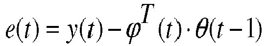
- Step 2: Calculate the identification error e(t) :
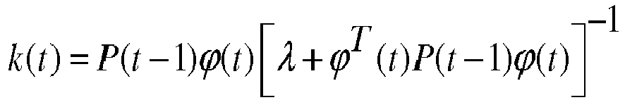
- Step 3: Calculate the gain k(t) :
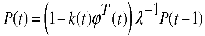
- Step 4: Calculate the covariance matrix:
- Step 5: Update the unknown parameter:

- Step 6:
Repeat Steps 1 through 5 for each time step. - In
FIGS. 9A through 9D , experimental validation graphs are shown. The performance of the RLS based tire longitudinal stiffness estimation algorithm is evaluated with simulations where the road surface is designed to have sudden friction coefficient changes, and the vehicle maneuver is straight driving with intermittent gas pedal presses. InFIG. 9A , slip ratio (percent) over time is graphed, and inFIG. 9B , tire-road friction coefficient over time is shown.FIG. 9C shows the algorithm activation signal andFIG. 9D the parameter estimation results, graphing longitudinal stiffness (Cx) for both actual and estimated values. It can be seen that the estimator shows delayed estimation at the first change due to lack of excitation at that time. Once excitation occurs at 2.2 seconds, the estimator updates the longitudinal stiffness. The results confirms that estimated longitudinal stiffness (broken line) closely matches actual (solid line). -
FIGS. 10A and 10B show a schematic block diagram of how the above friction estimation may be used in a sensor fusion approach for improved road surface classification. As explained above, tire-based inputs of tire ID, pressure and temperature are obtained from a tire-based TPMS Sensor Module. The tire wear state and tire load inputs are derived, either directly from tire sensors or indirectly from vehicle based sensors, and with the tire-based inputs, are used to compute the friction estimation from the expression: longitudinal stiffness (actual) = longitudinal stiffness (model based) X Friction Factor.Block 50 represents a summary of the friction estimation step. - In order to classify wet surfaces into a
detailed condition analysis 52, temperature sensors are used to detectambient air temperature 54 andrain sensors 56 are used to detect moisture in a moisture activatedsystem 56. Both air temperature and moisture sensor inputs with thefriction estimate 22 from the system and method described previously in reference toFIG. 7 are inputs into a detailedroad surface classifier 58 in the form of a Modified Sensor Fusion Algorithm using principles of Fuzzy logic. - From the Modified Sensor Fusion Algorithm, a Road Surface Type is determined. The table in
FIG. 10B shows a comparison between basic surface types and the surface types determined from the Modified Sensor Fusion Algorithm approach. - The Road Surface Classifier performance is shown graphically in
FIGS. 11 and12 . The performance of the RLS based Road Surface Classifier algorithm is evaluated with simulations where the road surface is designed to have sudden friction coefficient changes and the vehicle maneuver is straight driving with intermittent gas pedal presses. InFIG. 11 , friction is plotted over time for actual, predicted (without adaptation) and predicted (with tire pressure, temperature, wear, load state adaptation). Performance of the road surface classifier was evaluated for a worn tire (2 mm tread) on different road surface conditions. Without the wear state adaptation scaling factor, slip slope based model overestimates the grip/friction level (see black dasheddotted line 62 inFIG. 11 ). This is due to the fact that, without adaptation, the increased longitudinal stiffness of the tire is incorrectly attributed to an increased road surface friction level when, in reality, the increased stiffness is due to a decrease in the tire tread depth (a worn tire having a higher stiffness). - The adaptation model (see line 66) correctly compensates for this effect and estimates the grip level correctly in correlation to actual 64.
-
FIG. 12 demonstrates the Road Surface Classifier performance graphically for a hot tire (55°C). InFIG. 12 , friction is plotted over time for actual, predicted (without adaptation) and predicted (with tire pressure, temperature, wear, load state adaptation). Performance of the road surface classifier was evaluated for a worn tire (2 mm tread) on different road surface conditions. Without the temperature state adaptation scaling factor, slip slope based model overestimates the grip/friction level (see black dasheddotted line 68 inFIG. 11 ). This is due to the fact that, without adaptation, the decreased longitudinal stiffness of the tire is incorrectly attributed to a decreased road surface friction level when, in reality, the decreased stiffness is due to an increase in the tire temperature (a hotter tire having a lower stiffness). The adaptation model (see plotted line 70) correctly compensates for this effect and estimates the grip level correctly in correlation to actual 72. - It will be appreciated that tire-road friction coefficient information is of importance for vehicle dynamic control such as yaw stability control, braking control, trajectory tracking control and rollover prevention. Existing tire-road friction coefficient estimation approaches require certain levels of vehicle longitudinal and/or lateral motion excitations (e.g. accelerating, decelerating, and steering) to satisfy the persistence of excitation condition for reliable estimations.
- One approach taken in assessing friction is to estimate the longitudinal stiffness, i.e. the incline of the tire force relative to slip at low slips and from this value distinguish between different surface conditions. This method is more commonly known as the "slip-slope method" for friction coefficient estimation. Good estimations from this approach, however, in the low slip region are unpredictable.
- The subject system and method uses adaption parameters in order to achieve a better tire-road friction estimation, including within the low slip region. Adaption parameters are used which govern tire longitudinal stiffness behavior in the low slip region and include inflation pressure, tread depth, normal loading and temperature. Using only the value of slip-slope itself cannot derive a maximum friction coefficient and is, accordingly, a less than satisfactory friction estimation solution.
- The subject system and method utilizes tire-based attached sensor systems to compensate for dependencies such as pressure, temperature, wear state, tire construction. Consequently, the subject system and methodology can then isolate/alienate the effect of friction on the tire longitudinal stiffness. Using a tire attached TPMS sensor in conjunction with information from vehicle-based sensors compensates for the various operating conditions a tire experiences in real-world driving scenarios.
- As a first step and as explained above, a longitudinal stiffness adaptation model is developed and implemented for generating a model-based tire longitudinal stiffness prediction under various operating conditions a tire experiences. The adaptation model uses scaling factors to account for the effects of load, inflation pressure, temperature, tire wear-state, and tire type (summer/winter/all season) on the tire longitudinal stiffness. The tire construction (tire ID), inflation pressure, and temperature information is available from a tire-attached TPMS sensor module. The tire wear state and load information is available directly from tire attached sensors or indirectly from vehicle based sensors (suspension deflection for load and hub acceleration for wear state).
- In parallel with the model-based estimation of longitudinal stiffness, an on-vehicle (real time) estimate of the tire longitudinal stiffness is made following a three-step estimation procedure:
- (1) estimate the longitudinal tire force (using a sliding mode observer that relies on engine torque and brake torque measurements and wheel speed measurement available over the CAN bus of the vehicle);
- (2) estimate the tire longitudinal slip ratio (using kinematic relationship);
- (3) calculate the longitudinal stiffness (using a recursive least square algorithm with a forgetting factor).
- Finally, an estimate of the tire road surface condition is made by comparing the model-based estimate of stiffness to the actual tire longitudinal stiffness measured on the vehicle. The proportioning factor between the model-based estimate and the actual longitudinal stiffness is a direct measure of the tire road friction coefficient (µ).
- It will be noted that the subject system and method develops real-time friction coefficient estimation algorithms based on slip-slope calculations for each tire rather than focusing on "average" friction coefficient for the vehicle. Accordingly, the subject system and method provides information about the individual wheel tire-road friction coefficients, a more valuable measurement for active safety systems than average vehicle-based friction measurements.
Claims (15)
- A tire-based system for estimating road surface friction, the system comprising:at least one tire (12) mounted to a wheel hub and supporting a vehicle (14);model-based longitudinal stiffness estimating means for producing a model-based longitudinal stiffness estimation (46) for the at least one tire (12) from tire-based inputs and vehicle-based inputs;actual longitudinal stiffness estimating means for producing an actual longitudinal stiffness estimation (36) from vehicle-based inputs; andtire road friction estimating means for deriving a road friction estimation (22) from a comparative analysis between the actual longitudinal stiffness estimation (36) and the model-based longitudinal stiffness estimation (46).
- The system of claim 1, wherein the tire-based inputs are at least one input selected from the group:a measured air cavity pressure of the at least one tire (12);a tire-specific construction characteristics of the at least one tire (12);a measured temperature of the at least one tire (12).
- The system of claim 1 or 2, wherein the vehicle-based inputs are at least one input selected from the group:a measured wheel speed of the vehicle (14);a measured wheel torque;a measured hub vertical acceleration;a measured wheel slip ratio.
- The system of at least one of the previous claims, further comprising tire wear state estimating means (38) for producing a wear state estimation for the at least one tire preferably using or from the measured hub vertical acceleration.
- The system of claim 4, wherein the tire wear state estimating means (38) is configured to operably produce a tire wear state estimation from a detected shift in a vertical mode of the at least one tire (12).
- The system of at least one of the previous claims, wherein the model-based longitudinal stiffness estimating means is configured to algorithmically calculate the longitudinal stiffness estimation (46) from inputs including vehicle load, a measured air cavity pressure of the at least one tire (12) and a measured temperature of the at least one tire (12) preferably compensated by the estimated tire wear state.
- The system of at least one of the previous claims, wherein the actual longitudinal stiffness estimating means comprises a longitudinal force estimation means for generating a longitudinal force estimation from a measured wheel speed and a measured wheel torque; and/or wherein the longitudinal force estimation means comprises a sliding mode observer model.
- The system of at least one of the previous claims, wherein the actual longitudinal stiffness estimation means is configured to calculate the actual longitudinal stiffness estimation from the longitudinal force estimation and a measured wheel slip ratio; and/or wherein the actual longitudinal stiffness estimating means comprises a recursive least square algorithm with forgetting factor.
- The system of at least one of the previous claims, further comprising a road surface classifier algorithm for operably conducting a road surface type analysis based on the road friction estimation, an ambient air temperature measurement, and an ambient air moisture measurement, said road surface classifier algorithm preferably comprising a modified sensor fusion algorithm.
- A tire-based method of estimating road surface friction based on at least one tire (12) mounted to a wheel hub and supporting a vehicle (14), the method comprising:generating a model-based longitudinal stiffness estimation (46) from tire-based parameter inputs from the at least one tire (12) and vehicle-based parameter inputs;generating an actual longitudinal stiffness estimation (36) from vehicle-based parameter inputs; andderiving a tire road friction estimation (22) from a comparative analysis between the actual longitudinal stiffness estimation (36) and the model-based longitudinal stiffness estimation (46).
- The method of claim 10, further comprising using as the tire-based parameter inputs from the at least one tire (12) at least one parameter input selected from the group:a measured air cavity pressure of the at least one tire (12);one or more tire-specific construction specifications of the at least one tire (12);a temperature of the at least one tire (12).
- The method of claim 10 or 11, further comprising using as the vehicle-based parameter inputs from the vehicle (14) at least one input selected from the group:a measured wheel speed of the vehicle (14);a measured wheel torque;a measured hub vertical acceleration;a measured wheel slip ratio.
- The method of at least one of the claims 10 to 12, further comprising generating a tire wear state estimation of the at least one tire (12) from a measured hub vertical acceleration by detecting a shift in a vertical mode of the at least one tire (12); and/or generating a longitudinal stiffness estimation from vehicle-based input parameters including a vehicle load estimation, a measured air cavity pressure of the at least one tire (12), and a measured temperature of the at least one tire (12) preferably compensated by a wear state estimation of the at least one tire (12).
- The method of at least one of the claims 10 to 13, further comprising making a longitudinal force estimation from the measured wheel speed and the measured wheel torque; and/or using a sliding mode observer model in making a longitudinal force estimation.
- The method of at least one of the claims 10 to 14, further comprising utilizing a modified sensor fusion algorithm to determine a road surface type analysis using as parameter inputs a road friction estimation, an ambient air temperature measurement and an ambient air moisture measurement.
Applications Claiming Priority (1)
| Application Number | Priority Date | Filing Date | Title |
|---|---|---|---|
| US14/244,273 US9751533B2 (en) | 2014-04-03 | 2014-04-03 | Road surface friction and surface type estimation system and method |
Publications (2)
| Publication Number | Publication Date |
|---|---|
| EP2927065A1 true EP2927065A1 (en) | 2015-10-07 |
| EP2927065B1 EP2927065B1 (en) | 2017-01-11 |
Family
ID=52807614
Family Applications (1)
| Application Number | Title | Priority Date | Filing Date |
|---|---|---|---|
| EP15160946.8A Active EP2927065B1 (en) | 2014-04-03 | 2015-03-26 | Road surface friction and surface type estimation system and method |
Country Status (2)
| Country | Link |
|---|---|
| US (1) | US9751533B2 (en) |
| EP (1) | EP2927065B1 (en) |
Cited By (13)
| Publication number | Priority date | Publication date | Assignee | Title |
|---|---|---|---|---|
| CN106525452A (en) * | 2016-11-17 | 2017-03-22 | 安徽江淮汽车集团股份有限公司 | Method and system for testing heat fading performance |
| EP3178674A1 (en) * | 2015-12-09 | 2017-06-14 | The Goodyear Tire & Rubber Company | Tire sensor-based robust road surface roughness classification system and method |
| EP3378679A1 (en) * | 2017-03-23 | 2018-09-26 | The Goodyear Tire & Rubber Company | Model based tire wear estimation system and method |
| GB2562308A (en) * | 2017-05-12 | 2018-11-14 | Arrival Ltd | Regenerative braking control system |
| EP3587201A1 (en) * | 2018-06-21 | 2020-01-01 | Volvo Car Corporation | Method and system for determing tire-to-road friction in a vehicle |
| CN110765909A (en) * | 2019-10-14 | 2020-02-07 | 同济大学 | Vehicle-mounted camera-based auxiliary distributed driving electric automobile pavement estimation method |
| CN110789504A (en) * | 2019-10-18 | 2020-02-14 | 江苏大学 | Nonlinear composite ABS control method based on electromagnetic braking hysteresis compensation |
| US10603962B2 (en) | 2017-06-29 | 2020-03-31 | The Goodyear Tire & Rubber Company | Tire wear state estimation system and method |
| CN111391822A (en) * | 2020-03-27 | 2020-07-10 | 吉林大学 | Automobile transverse and longitudinal stability cooperative control method under limit working condition |
| EP3689699A1 (en) * | 2019-01-31 | 2020-08-05 | Toyo Tire Corporation | Tire force estimation system and tire force estimation method |
| US11498371B2 (en) | 2018-12-12 | 2022-11-15 | The Goodyear Tire & Rubber Company | Tire data information system |
| US11644386B2 (en) | 2018-12-11 | 2023-05-09 | The Goodyear Tire & Rubber Company | Tire wear state estimation system and method |
| WO2023083515A1 (en) * | 2021-11-15 | 2023-05-19 | Magna Pt B.V. & Co. Kg | Method for determining a road friction value |
Families Citing this family (27)
| Publication number | Priority date | Publication date | Assignee | Title |
|---|---|---|---|---|
| EP2992425A4 (en) * | 2013-04-30 | 2016-11-16 | Maxim Sokol Diamond | Methods and systems for monitoring roadway parameters |
| SE539221C2 (en) * | 2015-06-04 | 2017-05-23 | Scania Cv Ab | Method and control unit for avoiding an accident at a crosswalk |
| ES2783374T3 (en) * | 2015-12-18 | 2020-09-17 | Nira Dynamics Ab | Tire stiffness estimate and road friction estimate |
| DE102016211728A1 (en) * | 2016-06-29 | 2018-01-04 | Trw Automotive U.S. Llc | Reibwertschätzer |
| US10011284B2 (en) | 2016-07-13 | 2018-07-03 | Mitsubishi Electric Research Laboratories, Inc. | System and method for determining state of stiffness of tires of vehicle |
| US20180154707A1 (en) * | 2016-12-05 | 2018-06-07 | The Goodyear Tire & Rubber Company | Indirect tire pressure and wear state estimation system and method |
| EP3398825B1 (en) * | 2017-05-03 | 2020-03-11 | Volvo Car Corporation | Method and system for computing a road friction estimate |
| JP2019006351A (en) * | 2017-06-28 | 2019-01-17 | 株式会社ブリヂストン | Road surface state estimation method and road surface state estimation device |
| DE102018200330A1 (en) * | 2018-01-11 | 2019-07-11 | Robert Bosch Gmbh | Method for determining the current road surface roughness in a vehicle |
| JP2019137163A (en) * | 2018-02-08 | 2019-08-22 | トヨタ自動車株式会社 | Slip rate calculation device |
| JP7010152B2 (en) * | 2018-06-14 | 2022-02-10 | トヨタ自動車株式会社 | Vehicle brake control device |
| JP7070155B2 (en) * | 2018-06-27 | 2022-05-18 | 株式会社デンソー | Road surface condition determination device and tire system equipped with it |
| CN109159787A (en) * | 2018-08-31 | 2019-01-08 | 上海大学 | A kind of electric car tire attachment stable state real-time detecting system and method |
| DE102018132157B3 (en) * | 2018-12-13 | 2020-06-18 | Nira Dynamics Ab | Tire stiffness estimation and road friction estimation |
| US11254315B2 (en) * | 2019-03-12 | 2022-02-22 | Mitsubishi Electric Research Laboratories, Inc. | Friction adaptive vehicle control |
| US20200380805A1 (en) * | 2019-05-27 | 2020-12-03 | Jtekt Corporation | System for determining tire state |
| DE102020113936A1 (en) * | 2019-05-27 | 2020-12-03 | Jtekt Corporation | System for predicting a road surface coefficient of friction |
| JP7338240B2 (en) * | 2019-05-27 | 2023-09-05 | 株式会社ジェイテクト | Tire condition determination system |
| US11027776B2 (en) * | 2019-07-11 | 2021-06-08 | GM Global Technology Operations LLC | System and method for adapting parameters used in target slip estimation |
| CN110395120A (en) * | 2019-08-14 | 2019-11-01 | 厦门金龙联合汽车工业有限公司 | A kind of weaving control method of four-wheel distribution driving car |
| US11702084B2 (en) | 2019-11-25 | 2023-07-18 | The Goodyear Tire & Rubber Company | Vehicle sideslip angle estimation system and method |
| AU2021200226A1 (en) | 2020-01-28 | 2021-08-12 | The Goodyear Tire & Rubber Company | Method for estimating tire grip |
| KR102389160B1 (en) * | 2020-11-30 | 2022-04-25 | 주식회사 뉴로센스 | Method and apparatus for estimating road surface condition based on smart wheel sensor using machine-learning technique |
| CN112660136A (en) * | 2020-12-25 | 2021-04-16 | 清华大学 | Method and device for identifying road adhesion coefficient of automobile chassis dynamic domain controller |
| US11691465B1 (en) * | 2022-02-03 | 2023-07-04 | Sensata Technologies, Inc. | System and method for estimating tire load |
| CN114212074B (en) * | 2022-02-22 | 2022-04-29 | 北京航空航天大学 | Vehicle active steering rollover prevention control method based on road adhesion coefficient estimation |
| CN117671962B (en) * | 2024-01-31 | 2024-04-19 | 四川康新高速公路有限责任公司 | Method and device for analyzing vehicle out-of-control state aiming at long longitudinal slope section of expressway |
Citations (7)
| Publication number | Priority date | Publication date | Assignee | Title |
|---|---|---|---|---|
| WO2003074337A1 (en) * | 2002-03-01 | 2003-09-12 | Continental Teves Ag & Co. Ohg | Method for determining a maximum coefficient of friction |
| EP1378378A1 (en) * | 2002-07-04 | 2004-01-07 | Société de Technologie Michelin | Tire wear estimation |
| US20080053210A1 (en) * | 2006-09-06 | 2008-03-06 | Michelin Recherche Et Technique S.A. | Method of determining a maximum adhesion coefficient of a tire |
| EP1964736A1 (en) * | 2007-03-01 | 2008-09-03 | Haldex Brake Products AB | Systems and methods for determining a parameter relating to a tire-to-road contact and/or relation between a wheel and a vehicle motion |
| EP2138372A1 (en) * | 2008-06-26 | 2009-12-30 | Ford Global Technologies, LLC | Vehicle-to-road contact estimation |
| US20120179327A1 (en) * | 2011-01-10 | 2012-07-12 | GM Global Technology Operations LLC | Linear and non-linear identification of the longitudinal tire-road friction coefficient |
| US20140366618A1 (en) | 2013-06-14 | 2014-12-18 | Kanwar Bharat Singh | Tire wear state estimation system and method |
Family Cites Families (12)
| Publication number | Priority date | Publication date | Assignee | Title |
|---|---|---|---|---|
| JP3671134B2 (en) * | 2000-04-05 | 2005-07-13 | 株式会社豊田中央研究所 | Tire parameter estimation device |
| DE10320828A1 (en) * | 2003-05-08 | 2004-12-09 | Robert Bosch Gmbh | Optimization of vehicle dynamics control using tire information |
| US7552628B2 (en) | 2003-10-24 | 2009-06-30 | Pirelli Pneumatici S.P.A. | Method and system for determining a cornering angle of a tyre during the running of a vehicle |
| JP4680532B2 (en) | 2004-06-02 | 2011-05-11 | 株式会社ブリヂストン | Method and apparatus for estimating dynamic state of tire |
| DE602004012903T2 (en) | 2004-09-29 | 2009-04-09 | Pirelli Tyre S.P.A. | METHOD AND SYSTEM FOR DETERMINING THE SCROLLING ANGLE OF A TIRE WHILE DRIVING A VEHICLE |
| JP5121445B2 (en) | 2005-03-24 | 2013-01-16 | 株式会社ブリヂストン | Estimation method of tire slip angle |
| US7970512B2 (en) * | 2006-08-30 | 2011-06-28 | Ford Global Technologies | Integrated control system for stability control of yaw, roll and lateral motion of a driving vehicle using an integrated sensing system with pitch information |
| WO2008133150A1 (en) * | 2007-04-17 | 2008-11-06 | Nissan Motor Co., Ltd. | Device and method for estimating frictional condition of ground contact surface of wheel |
| JP5072463B2 (en) * | 2007-07-11 | 2012-11-14 | 株式会社ブリヂストン | Tire wear detection method and tire wear detection device |
| FI124059B (en) * | 2008-09-19 | 2014-02-28 | Aalto Korkeakoulusaeaetioe | Improvement in vehicle operating system |
| IT1393072B1 (en) | 2008-10-24 | 2012-04-11 | Pirelli | METHOD AND SYSTEM FOR REPORTING A CONDITION OF AQUAPLANO OF A TIRE ASSEMBLED ON A VEHICLE |
| WO2011054363A1 (en) | 2009-11-04 | 2011-05-12 | Nira Dynamics Ab | Surface classification |
-
2014
- 2014-04-03 US US14/244,273 patent/US9751533B2/en active Active
-
2015
- 2015-03-26 EP EP15160946.8A patent/EP2927065B1/en active Active
Patent Citations (7)
| Publication number | Priority date | Publication date | Assignee | Title |
|---|---|---|---|---|
| WO2003074337A1 (en) * | 2002-03-01 | 2003-09-12 | Continental Teves Ag & Co. Ohg | Method for determining a maximum coefficient of friction |
| EP1378378A1 (en) * | 2002-07-04 | 2004-01-07 | Société de Technologie Michelin | Tire wear estimation |
| US20080053210A1 (en) * | 2006-09-06 | 2008-03-06 | Michelin Recherche Et Technique S.A. | Method of determining a maximum adhesion coefficient of a tire |
| EP1964736A1 (en) * | 2007-03-01 | 2008-09-03 | Haldex Brake Products AB | Systems and methods for determining a parameter relating to a tire-to-road contact and/or relation between a wheel and a vehicle motion |
| EP2138372A1 (en) * | 2008-06-26 | 2009-12-30 | Ford Global Technologies, LLC | Vehicle-to-road contact estimation |
| US20120179327A1 (en) * | 2011-01-10 | 2012-07-12 | GM Global Technology Operations LLC | Linear and non-linear identification of the longitudinal tire-road friction coefficient |
| US20140366618A1 (en) | 2013-06-14 | 2014-12-18 | Kanwar Bharat Singh | Tire wear state estimation system and method |
Cited By (21)
| Publication number | Priority date | Publication date | Assignee | Title |
|---|---|---|---|---|
| EP3178674A1 (en) * | 2015-12-09 | 2017-06-14 | The Goodyear Tire & Rubber Company | Tire sensor-based robust road surface roughness classification system and method |
| US20170166019A1 (en) * | 2015-12-09 | 2017-06-15 | The Goodyear Tire & Rubber Company | Tire sensor-based robust road surface roughness classification system and method |
| US9840118B2 (en) * | 2015-12-09 | 2017-12-12 | The Goodyear Tire & Rubber Company | Tire sensor-based robust road surface roughness classification system and method |
| CN106525452A (en) * | 2016-11-17 | 2017-03-22 | 安徽江淮汽车集团股份有限公司 | Method and system for testing heat fading performance |
| CN106525452B (en) * | 2016-11-17 | 2019-05-28 | 安徽江淮汽车集团股份有限公司 | The test method and test macro of character of heat-fading energy |
| EP3378679A1 (en) * | 2017-03-23 | 2018-09-26 | The Goodyear Tire & Rubber Company | Model based tire wear estimation system and method |
| EP3378679B1 (en) | 2017-03-23 | 2021-07-28 | The Goodyear Tire & Rubber Company | Model based tire wear estimation system and method |
| GB2562308A (en) * | 2017-05-12 | 2018-11-14 | Arrival Ltd | Regenerative braking control system |
| GB2562308B (en) * | 2017-05-12 | 2022-10-26 | Arrival Ltd | Regenerative braking control system |
| US10603962B2 (en) | 2017-06-29 | 2020-03-31 | The Goodyear Tire & Rubber Company | Tire wear state estimation system and method |
| US11198442B2 (en) | 2018-06-21 | 2021-12-14 | Volvo Car Corporation | Method and system for determining tire-to-road friction in a vehicle |
| EP3587201A1 (en) * | 2018-06-21 | 2020-01-01 | Volvo Car Corporation | Method and system for determing tire-to-road friction in a vehicle |
| US11644386B2 (en) | 2018-12-11 | 2023-05-09 | The Goodyear Tire & Rubber Company | Tire wear state estimation system and method |
| US11498371B2 (en) | 2018-12-12 | 2022-11-15 | The Goodyear Tire & Rubber Company | Tire data information system |
| EP3689699A1 (en) * | 2019-01-31 | 2020-08-05 | Toyo Tire Corporation | Tire force estimation system and tire force estimation method |
| CN110765909A (en) * | 2019-10-14 | 2020-02-07 | 同济大学 | Vehicle-mounted camera-based auxiliary distributed driving electric automobile pavement estimation method |
| CN110765909B (en) * | 2019-10-14 | 2023-06-02 | 同济大学 | Road surface estimation method based on vehicle-mounted camera auxiliary distributed driving electric vehicle |
| CN110789504A (en) * | 2019-10-18 | 2020-02-14 | 江苏大学 | Nonlinear composite ABS control method based on electromagnetic braking hysteresis compensation |
| CN111391822A (en) * | 2020-03-27 | 2020-07-10 | 吉林大学 | Automobile transverse and longitudinal stability cooperative control method under limit working condition |
| CN111391822B (en) * | 2020-03-27 | 2022-06-24 | 吉林大学 | Automobile transverse and longitudinal stability cooperative control method under limit working condition |
| WO2023083515A1 (en) * | 2021-11-15 | 2023-05-19 | Magna Pt B.V. & Co. Kg | Method for determining a road friction value |
Also Published As
| Publication number | Publication date |
|---|---|
| US20150284006A1 (en) | 2015-10-08 |
| EP2927065B1 (en) | 2017-01-11 |
| US9751533B2 (en) | 2017-09-05 |
Similar Documents
| Publication | Publication Date | Title |
|---|---|---|
| EP2927065B1 (en) | Road surface friction and surface type estimation system and method | |
| EP2927066B1 (en) | Model-based longitudinal stiffness estimation system and method | |
| EP3028909B1 (en) | Intelligent tire-based road friction estimation system and method | |
| EP3115765B1 (en) | Tire sensor-based vehicle state estimation system and method | |
| JP4140720B2 (en) | Vehicle behavior reproduction system | |
| EP2957440B1 (en) | Tire temperature predictive system and method | |
| EP2778631B1 (en) | Vehicle dynamic load estimation system and method | |
| EP2865572A1 (en) | Road friction estimation system and method | |
| EP3023761B1 (en) | Tire cornering stiffness estimation system and method | |
| EP2777999B1 (en) | Dynamic tire slip angle estimation system and method | |
| JP2019513613A (en) | Method, system and non-transitory computer readable memory for controlling a vehicle | |
| US9821815B2 (en) | Estimating adhesion potential by assessing rolling radius | |
| US20090177346A1 (en) | Dynamic estimation of vehicle inertial parameters and tire forces from tire sensors | |
| EP3017971B1 (en) | Tire sensor-based vehicle control system optimization and method | |
| EP3318422A1 (en) | Indirect tire wear state prediction system and method | |
| Shim et al. | Model-based road friction estimation | |
| CN107933563A (en) | For determining the method and system to rub between ground and vehicle tyre | |
| JP4922062B2 (en) | Automotive electronic stability program | |
| EP3894289A1 (en) | Tire stiffness estimation and road friction estimation | |
| JP2008265545A (en) | Center of gravity position estimating device of vehicle and center of gravity position/yaw inertia moment estimating device | |
| US20220169255A1 (en) | Travel control system and travel control method | |
| CN113460056B (en) | Vehicle road surface adhesion coefficient estimation method based on Kalman filtering and least square method | |
| WO2023212001A1 (en) | Method and system for tire-road friction coefficient estimation | |
| US11926329B2 (en) | Motor vehicle control module and method, comprising an evaluation of rear wheel speed based on the front wheels only | |
| US11970155B2 (en) | Apparatus and method for improving turning performance of vehicle |
Legal Events
| Date | Code | Title | Description |
|---|---|---|---|
| PUAI | Public reference made under article 153(3) epc to a published international application that has entered the european phase |
Free format text: ORIGINAL CODE: 0009012 |
|
| AK | Designated contracting states |
Kind code of ref document: A1 Designated state(s): AL AT BE BG CH CY CZ DE DK EE ES FI FR GB GR HR HU IE IS IT LI LT LU LV MC MK MT NL NO PL PT RO RS SE SI SK SM TR |
|
| AX | Request for extension of the european patent |
Extension state: BA ME |
|
| 17P | Request for examination filed |
Effective date: 20160407 |
|
| RBV | Designated contracting states (corrected) |
Designated state(s): AL AT BE BG CH CY CZ DE DK EE ES FI FR GB GR HR HU IE IS IT LI LT LU LV MC MK MT NL NO PL PT RO RS SE SI SK SM TR |
|
| GRAP | Despatch of communication of intention to grant a patent |
Free format text: ORIGINAL CODE: EPIDOSNIGR1 |
|
| RIC1 | Information provided on ipc code assigned before grant |
Ipc: B60T 8/172 20060101AFI20160729BHEP |
|
| INTG | Intention to grant announced |
Effective date: 20160822 |
|
| GRAS | Grant fee paid |
Free format text: ORIGINAL CODE: EPIDOSNIGR3 |
|
| GRAA | (expected) grant |
Free format text: ORIGINAL CODE: 0009210 |
|
| AK | Designated contracting states |
Kind code of ref document: B1 Designated state(s): AL AT BE BG CH CY CZ DE DK EE ES FI FR GB GR HR HU IE IS IT LI LT LU LV MC MK MT NL NO PL PT RO RS SE SI SK SM TR |
|
| REG | Reference to a national code |
Ref country code: GB Ref legal event code: FG4D |
|
| REG | Reference to a national code |
Ref country code: CH Ref legal event code: EP |
|
| REG | Reference to a national code |
Ref country code: AT Ref legal event code: REF Ref document number: 860949 Country of ref document: AT Kind code of ref document: T Effective date: 20170115 |
|
| REG | Reference to a national code |
Ref country code: IE Ref legal event code: FG4D |
|
| REG | Reference to a national code |
Ref country code: FR Ref legal event code: PLFP Year of fee payment: 3 |
|
| REG | Reference to a national code |
Ref country code: DE Ref legal event code: R096 Ref document number: 602015001248 Country of ref document: DE |
|
| REG | Reference to a national code |
Ref country code: LT Ref legal event code: MG4D |
|
| REG | Reference to a national code |
Ref country code: NL Ref legal event code: MP Effective date: 20170111 |
|
| REG | Reference to a national code |
Ref country code: AT Ref legal event code: MK05 Ref document number: 860949 Country of ref document: AT Kind code of ref document: T Effective date: 20170111 |
|
| PG25 | Lapsed in a contracting state [announced via postgrant information from national office to epo] |
Ref country code: NL Free format text: LAPSE BECAUSE OF FAILURE TO SUBMIT A TRANSLATION OF THE DESCRIPTION OR TO PAY THE FEE WITHIN THE PRESCRIBED TIME-LIMIT Effective date: 20170111 |
|
| PG25 | Lapsed in a contracting state [announced via postgrant information from national office to epo] |
Ref country code: HR Free format text: LAPSE BECAUSE OF FAILURE TO SUBMIT A TRANSLATION OF THE DESCRIPTION OR TO PAY THE FEE WITHIN THE PRESCRIBED TIME-LIMIT Effective date: 20170111 Ref country code: LT Free format text: LAPSE BECAUSE OF FAILURE TO SUBMIT A TRANSLATION OF THE DESCRIPTION OR TO PAY THE FEE WITHIN THE PRESCRIBED TIME-LIMIT Effective date: 20170111 Ref country code: IS Free format text: LAPSE BECAUSE OF FAILURE TO SUBMIT A TRANSLATION OF THE DESCRIPTION OR TO PAY THE FEE WITHIN THE PRESCRIBED TIME-LIMIT Effective date: 20170511 Ref country code: FI Free format text: LAPSE BECAUSE OF FAILURE TO SUBMIT A TRANSLATION OF THE DESCRIPTION OR TO PAY THE FEE WITHIN THE PRESCRIBED TIME-LIMIT Effective date: 20170111 Ref country code: NO Free format text: LAPSE BECAUSE OF FAILURE TO SUBMIT A TRANSLATION OF THE DESCRIPTION OR TO PAY THE FEE WITHIN THE PRESCRIBED TIME-LIMIT Effective date: 20170411 Ref country code: GR Free format text: LAPSE BECAUSE OF FAILURE TO SUBMIT A TRANSLATION OF THE DESCRIPTION OR TO PAY THE FEE WITHIN THE PRESCRIBED TIME-LIMIT Effective date: 20170412 |
|
| PG25 | Lapsed in a contracting state [announced via postgrant information from national office to epo] |
Ref country code: BG Free format text: LAPSE BECAUSE OF FAILURE TO SUBMIT A TRANSLATION OF THE DESCRIPTION OR TO PAY THE FEE WITHIN THE PRESCRIBED TIME-LIMIT Effective date: 20170411 Ref country code: AT Free format text: LAPSE BECAUSE OF FAILURE TO SUBMIT A TRANSLATION OF THE DESCRIPTION OR TO PAY THE FEE WITHIN THE PRESCRIBED TIME-LIMIT Effective date: 20170111 Ref country code: RS Free format text: LAPSE BECAUSE OF FAILURE TO SUBMIT A TRANSLATION OF THE DESCRIPTION OR TO PAY THE FEE WITHIN THE PRESCRIBED TIME-LIMIT Effective date: 20170111 Ref country code: PT Free format text: LAPSE BECAUSE OF FAILURE TO SUBMIT A TRANSLATION OF THE DESCRIPTION OR TO PAY THE FEE WITHIN THE PRESCRIBED TIME-LIMIT Effective date: 20170511 Ref country code: PL Free format text: LAPSE BECAUSE OF FAILURE TO SUBMIT A TRANSLATION OF THE DESCRIPTION OR TO PAY THE FEE WITHIN THE PRESCRIBED TIME-LIMIT Effective date: 20170111 Ref country code: LV Free format text: LAPSE BECAUSE OF FAILURE TO SUBMIT A TRANSLATION OF THE DESCRIPTION OR TO PAY THE FEE WITHIN THE PRESCRIBED TIME-LIMIT Effective date: 20170111 Ref country code: SE Free format text: LAPSE BECAUSE OF FAILURE TO SUBMIT A TRANSLATION OF THE DESCRIPTION OR TO PAY THE FEE WITHIN THE PRESCRIBED TIME-LIMIT Effective date: 20170111 Ref country code: ES Free format text: LAPSE BECAUSE OF FAILURE TO SUBMIT A TRANSLATION OF THE DESCRIPTION OR TO PAY THE FEE WITHIN THE PRESCRIBED TIME-LIMIT Effective date: 20170111 |
|
| REG | Reference to a national code |
Ref country code: DE Ref legal event code: R097 Ref document number: 602015001248 Country of ref document: DE |
|
| PG25 | Lapsed in a contracting state [announced via postgrant information from national office to epo] |
Ref country code: EE Free format text: LAPSE BECAUSE OF FAILURE TO SUBMIT A TRANSLATION OF THE DESCRIPTION OR TO PAY THE FEE WITHIN THE PRESCRIBED TIME-LIMIT Effective date: 20170111 Ref country code: CZ Free format text: LAPSE BECAUSE OF FAILURE TO SUBMIT A TRANSLATION OF THE DESCRIPTION OR TO PAY THE FEE WITHIN THE PRESCRIBED TIME-LIMIT Effective date: 20170111 Ref country code: SK Free format text: LAPSE BECAUSE OF FAILURE TO SUBMIT A TRANSLATION OF THE DESCRIPTION OR TO PAY THE FEE WITHIN THE PRESCRIBED TIME-LIMIT Effective date: 20170111 Ref country code: RO Free format text: LAPSE BECAUSE OF FAILURE TO SUBMIT A TRANSLATION OF THE DESCRIPTION OR TO PAY THE FEE WITHIN THE PRESCRIBED TIME-LIMIT Effective date: 20170111 |
|
| PLBE | No opposition filed within time limit |
Free format text: ORIGINAL CODE: 0009261 |
|
| STAA | Information on the status of an ep patent application or granted ep patent |
Free format text: STATUS: NO OPPOSITION FILED WITHIN TIME LIMIT |
|
| PG25 | Lapsed in a contracting state [announced via postgrant information from national office to epo] |
Ref country code: DK Free format text: LAPSE BECAUSE OF FAILURE TO SUBMIT A TRANSLATION OF THE DESCRIPTION OR TO PAY THE FEE WITHIN THE PRESCRIBED TIME-LIMIT Effective date: 20170111 Ref country code: SM Free format text: LAPSE BECAUSE OF FAILURE TO SUBMIT A TRANSLATION OF THE DESCRIPTION OR TO PAY THE FEE WITHIN THE PRESCRIBED TIME-LIMIT Effective date: 20170111 Ref country code: MC Free format text: LAPSE BECAUSE OF FAILURE TO SUBMIT A TRANSLATION OF THE DESCRIPTION OR TO PAY THE FEE WITHIN THE PRESCRIBED TIME-LIMIT Effective date: 20170111 |
|
| 26N | No opposition filed |
Effective date: 20171012 |
|
| REG | Reference to a national code |
Ref country code: IE Ref legal event code: MM4A |
|
| PG25 | Lapsed in a contracting state [announced via postgrant information from national office to epo] |
Ref country code: LU Free format text: LAPSE BECAUSE OF NON-PAYMENT OF DUE FEES Effective date: 20170326 |
|
| REG | Reference to a national code |
Ref country code: FR Ref legal event code: PLFP Year of fee payment: 4 |
|
| PG25 | Lapsed in a contracting state [announced via postgrant information from national office to epo] |
Ref country code: SI Free format text: LAPSE BECAUSE OF FAILURE TO SUBMIT A TRANSLATION OF THE DESCRIPTION OR TO PAY THE FEE WITHIN THE PRESCRIBED TIME-LIMIT Effective date: 20170111 Ref country code: IE Free format text: LAPSE BECAUSE OF NON-PAYMENT OF DUE FEES Effective date: 20170326 |
|
| REG | Reference to a national code |
Ref country code: BE Ref legal event code: MM Effective date: 20170331 |
|
| PG25 | Lapsed in a contracting state [announced via postgrant information from national office to epo] |
Ref country code: BE Free format text: LAPSE BECAUSE OF NON-PAYMENT OF DUE FEES Effective date: 20170331 |
|
| PG25 | Lapsed in a contracting state [announced via postgrant information from national office to epo] |
Ref country code: MT Free format text: LAPSE BECAUSE OF NON-PAYMENT OF DUE FEES Effective date: 20170326 |
|
| REG | Reference to a national code |
Ref country code: CH Ref legal event code: PL |
|
| PG25 | Lapsed in a contracting state [announced via postgrant information from national office to epo] |
Ref country code: LI Free format text: LAPSE BECAUSE OF NON-PAYMENT OF DUE FEES Effective date: 20180331 Ref country code: CH Free format text: LAPSE BECAUSE OF NON-PAYMENT OF DUE FEES Effective date: 20180331 |
|
| PG25 | Lapsed in a contracting state [announced via postgrant information from national office to epo] |
Ref country code: HU Free format text: LAPSE BECAUSE OF FAILURE TO SUBMIT A TRANSLATION OF THE DESCRIPTION OR TO PAY THE FEE WITHIN THE PRESCRIBED TIME-LIMIT; INVALID AB INITIO Effective date: 20150326 |
|
| PG25 | Lapsed in a contracting state [announced via postgrant information from national office to epo] |
Ref country code: CY Free format text: LAPSE BECAUSE OF FAILURE TO SUBMIT A TRANSLATION OF THE DESCRIPTION OR TO PAY THE FEE WITHIN THE PRESCRIBED TIME-LIMIT Effective date: 20170111 |
|
| GBPC | Gb: european patent ceased through non-payment of renewal fee |
Effective date: 20190326 |
|
| PG25 | Lapsed in a contracting state [announced via postgrant information from national office to epo] |
Ref country code: MK Free format text: LAPSE BECAUSE OF FAILURE TO SUBMIT A TRANSLATION OF THE DESCRIPTION OR TO PAY THE FEE WITHIN THE PRESCRIBED TIME-LIMIT Effective date: 20170111 |
|
| PG25 | Lapsed in a contracting state [announced via postgrant information from national office to epo] |
Ref country code: GB Free format text: LAPSE BECAUSE OF NON-PAYMENT OF DUE FEES Effective date: 20190326 |
|
| PG25 | Lapsed in a contracting state [announced via postgrant information from national office to epo] |
Ref country code: TR Free format text: LAPSE BECAUSE OF FAILURE TO SUBMIT A TRANSLATION OF THE DESCRIPTION OR TO PAY THE FEE WITHIN THE PRESCRIBED TIME-LIMIT Effective date: 20170111 |
|
| PG25 | Lapsed in a contracting state [announced via postgrant information from national office to epo] |
Ref country code: AL Free format text: LAPSE BECAUSE OF FAILURE TO SUBMIT A TRANSLATION OF THE DESCRIPTION OR TO PAY THE FEE WITHIN THE PRESCRIBED TIME-LIMIT Effective date: 20170111 |
|
| PGFP | Annual fee paid to national office [announced via postgrant information from national office to epo] |
Ref country code: IT Payment date: 20220210 Year of fee payment: 8 |
|
| PGFP | Annual fee paid to national office [announced via postgrant information from national office to epo] |
Ref country code: FR Payment date: 20230208 Year of fee payment: 9 |
|
| PGFP | Annual fee paid to national office [announced via postgrant information from national office to epo] |
Ref country code: DE Payment date: 20230131 Year of fee payment: 9 |