EP2865572A1 - Road friction estimation system and method - Google Patents
Road friction estimation system and method Download PDFInfo
- Publication number
- EP2865572A1 EP2865572A1 EP20140189835 EP14189835A EP2865572A1 EP 2865572 A1 EP2865572 A1 EP 2865572A1 EP 20140189835 EP20140189835 EP 20140189835 EP 14189835 A EP14189835 A EP 14189835A EP 2865572 A1 EP2865572 A1 EP 2865572A1
- Authority
- EP
- European Patent Office
- Prior art keywords
- estimation
- tire
- tires
- vehicle
- slip angle
- Prior art date
- Legal status (The legal status is an assumption and is not a legal conclusion. Google has not performed a legal analysis and makes no representation as to the accuracy of the status listed.)
- Withdrawn
Links
Images


Classifications
-
- B—PERFORMING OPERATIONS; TRANSPORTING
- B60—VEHICLES IN GENERAL
- B60T—VEHICLE BRAKE CONTROL SYSTEMS OR PARTS THEREOF; BRAKE CONTROL SYSTEMS OR PARTS THEREOF, IN GENERAL; ARRANGEMENT OF BRAKING ELEMENTS ON VEHICLES IN GENERAL; PORTABLE DEVICES FOR PREVENTING UNWANTED MOVEMENT OF VEHICLES; VEHICLE MODIFICATIONS TO FACILITATE COOLING OF BRAKES
- B60T8/00—Arrangements for adjusting wheel-braking force to meet varying vehicular or ground-surface conditions, e.g. limiting or varying distribution of braking force
- B60T8/17—Using electrical or electronic regulation means to control braking
- B60T8/172—Determining control parameters used in the regulation, e.g. by calculations involving measured or detected parameters
- B60T8/1725—Using tyre sensors, e.g. Sidewall Torsion sensors [SWT]
-
- B—PERFORMING OPERATIONS; TRANSPORTING
- B60—VEHICLES IN GENERAL
- B60T—VEHICLE BRAKE CONTROL SYSTEMS OR PARTS THEREOF; BRAKE CONTROL SYSTEMS OR PARTS THEREOF, IN GENERAL; ARRANGEMENT OF BRAKING ELEMENTS ON VEHICLES IN GENERAL; PORTABLE DEVICES FOR PREVENTING UNWANTED MOVEMENT OF VEHICLES; VEHICLE MODIFICATIONS TO FACILITATE COOLING OF BRAKES
- B60T2210/00—Detection or estimation of road or environment conditions; Detection or estimation of road shapes
- B60T2210/10—Detection or estimation of road conditions
- B60T2210/12—Friction
- B60T2210/122—Friction using fuzzy logic, neural computing
-
- B—PERFORMING OPERATIONS; TRANSPORTING
- B60—VEHICLES IN GENERAL
- B60T—VEHICLE BRAKE CONTROL SYSTEMS OR PARTS THEREOF; BRAKE CONTROL SYSTEMS OR PARTS THEREOF, IN GENERAL; ARRANGEMENT OF BRAKING ELEMENTS ON VEHICLES IN GENERAL; PORTABLE DEVICES FOR PREVENTING UNWANTED MOVEMENT OF VEHICLES; VEHICLE MODIFICATIONS TO FACILITATE COOLING OF BRAKES
- B60T2230/00—Monitoring, detecting special vehicle behaviour; Counteracting thereof
- B60T2230/02—Side slip angle, attitude angle, floating angle, drift angle
-
- B—PERFORMING OPERATIONS; TRANSPORTING
- B60—VEHICLES IN GENERAL
- B60T—VEHICLE BRAKE CONTROL SYSTEMS OR PARTS THEREOF; BRAKE CONTROL SYSTEMS OR PARTS THEREOF, IN GENERAL; ARRANGEMENT OF BRAKING ELEMENTS ON VEHICLES IN GENERAL; PORTABLE DEVICES FOR PREVENTING UNWANTED MOVEMENT OF VEHICLES; VEHICLE MODIFICATIONS TO FACILITATE COOLING OF BRAKES
- B60T2240/00—Monitoring, detecting wheel/tire behaviour; counteracting thereof
- B60T2240/04—Tire deformation
-
- B—PERFORMING OPERATIONS; TRANSPORTING
- B60—VEHICLES IN GENERAL
- B60T—VEHICLE BRAKE CONTROL SYSTEMS OR PARTS THEREOF; BRAKE CONTROL SYSTEMS OR PARTS THEREOF, IN GENERAL; ARRANGEMENT OF BRAKING ELEMENTS ON VEHICLES IN GENERAL; PORTABLE DEVICES FOR PREVENTING UNWANTED MOVEMENT OF VEHICLES; VEHICLE MODIFICATIONS TO FACILITATE COOLING OF BRAKES
- B60T2240/00—Monitoring, detecting wheel/tire behaviour; counteracting thereof
- B60T2240/06—Wheel load; Wheel lift
-
- B—PERFORMING OPERATIONS; TRANSPORTING
- B60—VEHICLES IN GENERAL
- B60T—VEHICLE BRAKE CONTROL SYSTEMS OR PARTS THEREOF; BRAKE CONTROL SYSTEMS OR PARTS THEREOF, IN GENERAL; ARRANGEMENT OF BRAKING ELEMENTS ON VEHICLES IN GENERAL; PORTABLE DEVICES FOR PREVENTING UNWANTED MOVEMENT OF VEHICLES; VEHICLE MODIFICATIONS TO FACILITATE COOLING OF BRAKES
- B60T2270/00—Further aspects of brake control systems not otherwise provided for
- B60T2270/86—Optimizing braking by using ESP vehicle or tire model
Definitions
- the invention relates generally to tire monitoring systems for collecting measured tire parameter data during vehicle operation and, more particularly, to a system and method for road friction estimation based upon such measurements.
- Vehicle-mounted tires may be monitored by tire pressure monitoring systems (TPMS) which measure tire parameters such as pressure and temperature during vehicle operation.
- TPMS tire pressure monitoring systems
- Data from TPMS tire-equipped systems is used to ascertain the status of a tire based on measured tire parameters and alert the driver of conditions, such as low tire pressure or leakage, which may require remedial maintenance.
- Sensors within each tire are either installed at a pre-cure stage of tire manufacture or in a post-cure assembly to the tire.
- the invention relates to a system in accordance with claim 1 and to a method in accordance with claim 9.
- a road friction coefficient estimation system and method for calculating a road friction coefficient estimation.
- tire load estimation sensors are attached for estimating a dynamic load estimation on each of the plurality of tires.
- Tire slip angle calculation is conducted utilizing load estimation sensor data, whereby a dynamic slip angle estimation on each of the plurality of tires is made.
- vehicle acceleration and yaw rate operational parameters are obtained and a dynamic observer model calculates lateral and longitudinal force estimates on each of the plurality of tires.
- a load transfer ratio is estimated from the estimated dynamic load on each of the plurality of tires; and an individual wheel force estimation is calculated on each of the plurality of tires from the lateral and longitudinal force estimates on each of the plurality of tires. From the dynamic slip angle estimation on each of the plurality of tires and the individual wheel force estimation on each of the plurality of tires, a model-based friction estimation is made.
- the friction estimation is conducted in real time based upon the tire sensor-obtained variables of slip angle and tire load and observer-derived estimations of forces on each of the plurality of tires.
- the dynamic observer model comprises a single-track, three degree-of-freedom model; the road friction coefficient estimation is made following a four-wheel vehicle model; and the road friction coefficient estimation is made utilizing a Brush-tire model.
- ANN Artificial Neural Network
- ANN neural networks are non-linear statistical data modeling tools used to model complex relationships between inputs and outputs or to find patterns in data.
- Axial and “axially” means lines or directions that are parallel to the axis of rotation of the tire.
- Brush model means a one-dimensional quasi-static mechanical analog system used for analysis of rolling resistance.
- the contact patch is divided into two sections: a forward static region where the tire tread adheres to the road surface, and an aft slide region where sliding occurs between tire and road.
- CAN bus is an abbreviation for controller area network.
- “Circumferential” means lines or directions extending along the perimeter of the surface of the annular tread perpendicular to the axial direction.
- Equatorial Centerplane means the plane perpendicular to the tire's axis of rotation and passing through the center of the tread.
- “Footprint” means the contact patch or area of contact created by the tire tread with a flat surface as the tire rotates or rolls.
- Inboard side means the side of the tire nearest the vehicle when the tire is mounted on a wheel and the wheel is mounted on the vehicle.
- “Lateral” means an axial direction.
- “Lateral edges” means a line tangent to the axially outermost tread contact patch or footprint as measured under normal load and tire inflation, the lines being parallel to the equatorial centerplane.
- Piezoelectric Film Sensor a device in the form of a film body that uses the piezoelectric effect actuated by a bending of the film body to measure pressure, acceleration, strain or force by converting them to an electrical charge.
- Ring and radially means directions radially toward or away from the axis of rotation of the tire.
- Slip Angle is the angle between a vehicle's direction of ravel and the direction in which the front wheels are pointing. Slip angle is a measurement of the deviation between the plane of tire rotation and the direction of travel of a tire.
- a strain sensor system and method of estimating a tire load and a tire slip angle is shown in a block level diagram.
- the load on a vehicle tire may be estimated by a tire based sensor system employing one or, preferably, a pair of strain or bending sensors 14 mounted to a tire at opposite sidewall locations 30.
- the strain sensors react to the sidewall deflections of the tire and, in measuring the extent of deflection, provide a basis for estimating both load and slip angle of the tire.
- a signal 16 from each of the bending sensors 14 is transmitted to a signal processor as will be explained.
- a tire pressure monitoring system 18 is mounted to the tire and functions to measure and transmit tire pressure data 20 to the signal processing unit..
- the tire sidewall strain sensor signal(s) are used in parallel signal processing paths; a first path which uses the signal (s) 16 to estimate tire load, indicated by path 22.
- the second processing path, indicated at numeral 24, uses the sidewall deflection information to estimate slip angle.
- US-A-2014/0069181 teaches the methodology and system of path 22 and is incorporated herein in its entirety by reference.
- the system is used on a vehicle equipped with tires of conventional construction, having a tread component at a tire crown region which contacts a ground surface during rolling operation.
- the tire mounts to a rim in conventional manner.
- the sensors are preferably piezoelectric bending sensors, or other suitable strain sensors commercially available, of a type operational to bend and reconfigure when subjected to a bending force and thereupon generate an electrical signal indicative of the magnitude of bending reconfiguration in the sensor body.
- the bending signals are thus indicative of the magnitude of the bending strain within the sidewall to which the sensor is attached.
- the sensor resumes its original configuration.
- a piezoelectric bending sensor such as bending film sensor commercially offered by Measurement Specialties, Inc. located at 1000 Lucas Way, Hampton, Virginia 23666 may be employed.
- slip Angle is the angle between a vehicle's direction of ravel and the direction in which the front wheels are pointing.
- Slip angle is a measurement of the deviation between the plane of tire rotation and the direction of travel of a tire.
- the slip angle of a moving vehicle tire is useful information in vehicle control and stability systems. As braking and other control systems in vehicles become more interrelated, an estimation of tire slip angle is useful in stability and control system such as anti-locking brakes.
- a slip angle estimation system is taught and disclosed by US-A-2014/0163816 likewise incorporated herein in its entirety by reference.
- the sensor signal(s) are analyzed by finding the signal peak, extracting the linear portion of the curve, and fitting a line to the extracted curve in a least squares sense. An estimate of the difference in the signal slope provides a basis for concluding the slip angle present in the tire.
- the signal processing represented by sequential steps of processes 22, 24 result in an estimation of tire load 26 and 28 on a continual basis as the tire is in use. Each tire is analyzed in respective application of processes 22, 24 to generate the load and slip angle for each using sidewall deflection information.
- inflation pressure is measured by a tire pressure monitoring system (TPMS) mounted to the tire, of a type commercially available.
- TPMS tire pressure monitoring system
- the TPMS system includes a pressure sensor that mounts to a tire in communication with an internal tire air cavity and functions to measure the air pressure within the tire cavity and transmit the measured pressure data to a receiver.
- the measurement of the TPMS may further include a temperature sensor that measures tire temperature. Measured pressure value is transmitted by the TPMS system for inclusion in the load and slip angle estimations 22, 24.
- FIG. 2 demonstrates coefficient of friction estimation in an exemplary four- wheeled vehicle 34.
- the system may be adapted to vehicles having more or fewer wheel assemblies if desired.
- the vehicle 34 is equipped with four tire/wheel assemblies 12.
- Vehicle based sensors are employed for the purpose of providing by means of vehicle CAN Bus 36 lateral and longitudinal acceleration data a x , a y ; and yaw rate "r" in a single point preview driver model output ⁇ .
- An observer 38 receives as input CAN Bus acceleration data a x , a y ; and yaw rate "r" data.
- the observer 38 is a sliding mode observer (SMC)-Single-track 3 degree of freedom (DOF) model. From the CAN-Bus data, the observer 38 functions to output total lateral force on the front and rear tires and total longitudinal force on the front tires for estimation of individual wheel force 40, using a four-wheel vehicle model as shown in FIG. 13 .
- SMC sliding mode observer
- the model may be implemented using any conventional commercial mathematical simulation tool such as, but not limited to Simulink commercially available from The Mathworks, Inc. located at 3 Apple Hill Drive, Natick, Massachusetts 01760.
- Simulink ® is a block diagram environment for multi-domain simulation and model based design. It supports system-level design, simulation, automatic code generation, and continuous test and verification of embedded systems. Simulink provides a graphical editor, customizable block libraries, and solvers for modeling and simulating dynamic systems. It is integrated with MATLAB ® , enabling a user to incorporate MATLAB algorithms into models and export simulation results to MATLAB for further analysis.
- individual wheel force estimations (block 40) are made using the above four-wheel vehicle model.
- the individual wheel force estimation outputs are applied to the friction estimation algorithm (Brush-tire model based) as shown by block 42, resulting in an estimation of road surface coefficient of friction 44.
- the "Brush Tire Model” represents a one-dimensional quasi-static mechanical analog system used for analysis of rolling resistance. In the Brush model, the contact patch is divided into two sections: a forward static region where the tire tread adheres to the road surface, and an aft slide region where sliding occurs between tire and road.
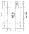
- FIG. 3A shows a graph of the steering angle vs. time in the double lane change maneuver on a road surface having a high mu condition of 0.8.
- FIG. 3B shows a vehicle path graphing longitudinal displacement [m] vs. lateral displacement [m].
- Estimation results are represented by FIGS. 4A, 4B , 5A, and 5B graphing F y [N] vs. time for the rear right, rear left, front right, and front left tires, respectively, for the double lane change maneuver (1).
- the close correlation between the actual and estimated force values validates the accuracy of the estimation approach.
- FIGS. 6A , 6B experimental results are shown for the second extreme cornering maneuver, that of a fish hook.
- the steering angle [Deg] is graphed over time.
- the vehicle path is graphed as longitudinal displacement vs. lateral displacement [m] and approximates the shape of a fishhook.
- Estimation results are represented by FIGS. 7A, 7B , 8A and 8B graphing F y [N] vs. time for the rear right, rear left, front right, and front left tires, respectively, for the fishhook path of maneuver (2).
- the close correlation between the actual and estimated force values validates the accuracy of the subject observer estimation approach.
- observer performance and experimental results are analyzed for a closed loop (y vs. x position) vehicle path followed by an experimental vehicle instrumented with an IMU (Inertial Measurement Unit) and force hubs of a type commercially available.
- An IMU is typically equipped to combine 3-axis accelerometers, 3-axis gyros, and/or 3-axis magnetic sensors for computing and outputting in real-time drift free three dimensional vehicle orientations that are continuous over a complete 360 degrees of motion. From the IMU, measurements of acceleration a x , a y , and yaw rate "r" are provided from the vehicle CAN Bus and inputted into the observer.
- FIG. 10A shows estimation results vs. actual [obtained from a force hub] for lateral tire force front; FIG. 10B for lateral tire force rear. The close correlation between estimated and actual results again confirms the validity of the subject observer-based estimation system and methodology.
- the sensor fusion approach combines the intelligent tire and vehicle information of tire load provided by the tire based TPMS unit 18 and the strain sensors 14 with the CAN bus information (a x , a y , and yaw rate "r") to estimate the individual wheel forces (using the Four-wheel Vehicle Model).
- a road friction estimation algorithm then utilizes the individual wheel forces and slip angle estimation to estimate the road surface coefficient of friction as explained below.
- the friction estimation algorithm utilizes the F x , F y , and F z (longitudinal, lateral, and normal) load estimations applied to the Brush tire model.
- FIG. 11 represents a Gough-plot using the Brush Tire Model.
- the ratio of Fy/Fz is plotted against the ratio -M z /F z Lines of constant friction coefficient (solid), constant side slip angle (dotted) and constant pneumatic trail (dash-dotted) are shown in the diagram of FIG. 11 . It will be noted that a pair of values (F y , M y ) are uniquely defined for each F y /F z coordinate for the model (1) above.
- the side force and self aligning torque are two linearly independent functions of side slip angle and friction coefficient, provided the tire is partially sliding. An estimate of friction can therefore be made as soon as the tire is partially sliding.
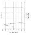
- FIG. 12 represents a graph of tire lateral force [N] vs. slip angle [degrees] for three coefficient of friction mu values of 1, 0.06, and 0.2. It will be appreciated that by determining lateral force vs. slip angle, an estimation of coefficient of friction can be made by solving equations (2) above for ⁇ .
- Friction coefficient estimation results are presented in the table below for three slip angle conditions. From the results, it is shown that the slip angle, normal force, and lateral force values define a unique estimation of friction coefficient for both low and high friction surfaces.
- the subject system and method of estimating a road coefficient of friction utilizes direct measurement of tire variables using wireless sensors 14 embedded inside the tire.
- Existing control systems have limited information regarding tire deformations, traction forces and road surface conditions.
- tire-based sensors provide accurate, reliable and real-time information about the magnitudes, directions, and limits of forces for each tire.
- accurate and real-time estimation of tire variables may be used to avoid tire saturation during an emergency maneuver.
- Early warning systems can benefit from these estimations to inform drivers about diminishing road traction abilities when the vehicle hits a slippery road surface or when the driver makes excessive steering.
- the information produced using the subject system and method namely the magnitudes, directions, and limits of forces for each tire_and estimation of road coefficient of friction, can be used in a predictive control framework in order to design more reliable lateral and longitudinal control systems for active systems.
- a primary disadvantage of the observer based techniques is that they do not work under steady state driving conditions, i.e. when the vehicle speed is constant and the steering wheel angle is close to zero. A minimum acceleration/deceleration or steering of the vehicle is required for tire-road friction coefficient parameter to converge to its correct value. Since the vehicle is not likely to always be accelerating/decelerating or cornering, this means that the friction coefficient cannot be continuously updated.
- a secondary disadvantage in known observer based techniques is that the slip and force observers are usually based on lateral /longitudinal vehicle models whose predictive outputs mis-predict during extreme combined maneuvers.
- the subject invention system and method presents a tire-vehicle integrated tire-road friction coefficient estimation approach which makes use of sensor information from an intelligent tire and vehicle CAN bus information [as shown in FIG. 2 ].
- the sensor signal 16 from an intelligent tire 12 [ FIG. 1 ] are used to estimate the tire dynamic load (F z ) 26 and slip angle 28.
- US-A- 2014/0069181 and US-A-2014/0163816 show estimation systems and methods for estimating load and slip angle based on strain sensor detected tire deformation.
- the vehicle CAN bus information is used to make an estimate of the tire lateral and longitudinal forces (F x , F y ) using a dynamic observer as shown in FIG. 2 .
Abstract
A road friction coefficient estimation system and method for providing or calculating a road friction coefficient estimation is provided. The system comprises at least one first or front tire and at least one second or rear tire supporting a vehicle; a tire load estimation means for estimating a first or front tire load estimation and a second or rear tire load estimation; a tire slip angle estimation means for estimating a first or front tire slip angle estimation and a second or rear tire slip angle estimation; a vehicle-based sensor means for measuring one or more vehicle operational parameters; an observer model for calculating an estimated total first or front tire force estimation and an estimated total second or rear tire force estimation based on the vehicle operational parameters; a load transfer ratio calculating means for calculating an estimated load transfer ratio from the first or front tire load estimation and the second or rear tire load estimation; an individual wheel force estimation means for calculating an individual wheel force estimation based on the estimated total forces on the first or front tire and the second or rear tire; and a model-based friction estimation means for calculating an estimate road surface friction coefficient based on the first or front tire slip angle estimation, the second or rear tire slip angle estimation, and the individual wheel force estimation.
Description
- The invention relates generally to tire monitoring systems for collecting measured tire parameter data during vehicle operation and, more particularly, to a system and method for road friction estimation based upon such measurements.
- Vehicle-mounted tires may be monitored by tire pressure monitoring systems (TPMS) which measure tire parameters such as pressure and temperature during vehicle operation. Data from TPMS tire-equipped systems is used to ascertain the status of a tire based on measured tire parameters and alert the driver of conditions, such as low tire pressure or leakage, which may require remedial maintenance. Sensors within each tire are either installed at a pre-cure stage of tire manufacture or in a post-cure assembly to the tire.
- Other factors such as the condition of the road surface including the road friction coefficient is an important considerations for vehicle operation and safety. It is accordingly further desirable to measure road friction and communicate road friction information to a vehicle operator and/or vehicle systems such as braking and stability.
- The invention relates to a system in accordance with
claim 1 and to a method in accordance withclaim 9. - Dependent claims refer to preferred embodiments of the invention.
- According to a preferred aspect of the invention a road friction coefficient estimation system and method is provided for calculating a road friction coefficient estimation. In a vehicle having a plurality of supporting tires, tire load estimation sensors are attached for estimating a dynamic load estimation on each of the plurality of tires. Tire slip angle calculation is conducted utilizing load estimation sensor data, whereby a dynamic slip angle estimation on each of the plurality of tires is made. From vehicle CAN bus sensors, vehicle acceleration and yaw rate operational parameters are obtained and a dynamic observer model calculates lateral and longitudinal force estimates on each of the plurality of tires. A load transfer ratio is estimated from the estimated dynamic load on each of the plurality of tires; and an individual wheel force estimation is calculated on each of the plurality of tires from the lateral and longitudinal force estimates on each of the plurality of tires. From the dynamic slip angle estimation on each of the plurality of tires and the individual wheel force estimation on each of the plurality of tires, a model-based friction estimation is made.
- In another preferred aspect, the friction estimation is conducted in real time based upon the tire sensor-obtained variables of slip angle and tire load and observer-derived estimations of forces on each of the plurality of tires.
- In a further preferred aspect, the dynamic observer model comprises a single-track, three degree-of-freedom model; the road friction coefficient estimation is made following a four-wheel vehicle model; and the road friction coefficient estimation is made utilizing a Brush-tire model.
- "ANN" or "Artificial Neural Network" is an adaptive tool for non-linear statistical data modeling that changes its structure based on external or internal information that flows through a network during a learning phase. ANN neural networks are non-linear statistical data modeling tools used to model complex relationships between inputs and outputs or to find patterns in data.
- "Axial" and "axially" means lines or directions that are parallel to the axis of rotation of the tire.
- "Brush model" means a one-dimensional quasi-static mechanical analog system used for analysis of rolling resistance. In the Brush model, the contact patch is divided into two sections: a forward static region where the tire tread adheres to the road surface, and an aft slide region where sliding occurs between tire and road.
- "CAN bus" is an abbreviation for controller area network.
- "Circumferential" means lines or directions extending along the perimeter of the surface of the annular tread perpendicular to the axial direction.
- "Equatorial Centerplane (CP)" means the plane perpendicular to the tire's axis of rotation and passing through the center of the tread.
- "Footprint" means the contact patch or area of contact created by the tire tread with a flat surface as the tire rotates or rolls.
- "Inboard side" means the side of the tire nearest the vehicle when the tire is mounted on a wheel and the wheel is mounted on the vehicle.
- "Lateral" means an axial direction.
- "Lateral edges" means a line tangent to the axially outermost tread contact patch or footprint as measured under normal load and tire inflation, the lines being parallel to the equatorial centerplane.
- "Piezoelectric Film Sensor" a device in the form of a film body that uses the piezoelectric effect actuated by a bending of the film body to measure pressure, acceleration, strain or force by converting them to an electrical charge.
- "Radial" and "radially" means directions radially toward or away from the axis of rotation of the tire.
- "Slip Angle" is the angle between a vehicle's direction of ravel and the direction in which the front wheels are pointing. Slip angle is a measurement of the deviation between the plane of tire rotation and the direction of travel of a tire.
- The invention will be described by way of example and with reference to the accompanying drawings in which:
-
FIG. 1 is a block level diagram of the system employed in the estimation of slip angle and load on a vehicle's tires. -
FIG. 2 is a block level diagram of the system for using tire load and slip angle ofFIG. 1 with the vehicle CAN Bus parameters in the estimation of wheel force and coefficient of friction. -
FIG. 3A is a graph of steering angle over time used in conducting system verification. -
FIG. 3B is a graph of lateral displacement [m] vs. longitudinal displacement [m] along a vehicle experimental path. -
FIG. 4A is a graph of lateral force Fy on the rear right tire over the path showing actual force and estimated. -
FIG. 4B is a graph of lateral force Fy on the rear left tire over the path showing actual vs. estimated comparative results. -
FIGS. 5A and 5B are graphs showing lateral force estimated vs. actual for the front right and front left tires, respectively. -
FIG.6A is a graph showing steering angle over time for the experimental vehicle path. -
FIG. 6B is a graph of longitudinal displacement [m] vs. lateral displacement [m] over the experimental vehicle path. -
FIGS. 7A and 7B are graphs showing lateral force estimated vs. actual for the right and left rear tires, respectively. -
FIGS. 8A and 8B are graphs showing lateral force estimated vs. actual for the right and left front tires, respectively. -
FIG.9 is a graph of an experimental vehicle path showing y and x vehicle position coordinates. -
FIGS. 10A and 10B are graphs showing lateral tire force actual (Force Hub) vs. Estimated (Observer) comparative results. -
FIG.11 is a Gough-plot using brush tire model. -
FIG. 12 is a graph of the brush tire model showing tire lateral force vs. slip angle for three coefficient of friction values: 1, 0.6, 0.2 at a normal loading Fz of 4000 N. -
FIG. 13 is a force diagram for a four wheeled vehicle. - Referring first to
FIG. 1 , a strain sensor system and method of estimating a tire load and a tire slip angle is shown in a block level diagram. The load on a vehicle tire may be estimated by a tire based sensor system employing one or, preferably, a pair of strain or bendingsensors 14 mounted to a tire atopposite sidewall locations 30. The strain sensors react to the sidewall deflections of the tire and, in measuring the extent of deflection, provide a basis for estimating both load and slip angle of the tire. Asignal 16 from each of the bendingsensors 14 is transmitted to a signal processor as will be explained. In addition, a tirepressure monitoring system 18 is mounted to the tire and functions to measure and transmittire pressure data 20 to the signal processing unit.. The tire sidewall strain sensor signal(s) are used in parallel signal processing paths; a first path which uses the signal (s) 16 to estimate tire load, indicated bypath 22. The second processing path, indicated atnumeral 24, uses the sidewall deflection information to estimate slip angle.US-A-2014/0069181 teaches the methodology and system ofpath 22 and is incorporated herein in its entirety by reference. The system is used on a vehicle equipped with tires of conventional construction, having a tread component at a tire crown region which contacts a ground surface during rolling operation. The tire mounts to a rim in conventional manner. The sensors are preferably piezoelectric bending sensors, or other suitable strain sensors commercially available, of a type operational to bend and reconfigure when subjected to a bending force and thereupon generate an electrical signal indicative of the magnitude of bending reconfiguration in the sensor body. The bending signals are thus indicative of the magnitude of the bending strain within the sidewall to which the sensor is attached. When the bending force is removed, the sensor resumes its original configuration. By way of example, without intent to limit the scope of the invention, a piezoelectric bending sensor such as bending film sensor commercially offered by Measurement Specialties, Inc. located at 1000 Lucas Way, Hampton, Virginia 23666 may be employed. - In addition, the lateral sidewall deflection of the tire is analyzed for the purpose of estimating the slip angle of the tire as indicated by the
vertical block path 24. "Slip Angle" is the angle between a vehicle's direction of ravel and the direction in which the front wheels are pointing. Slip angle is a measurement of the deviation between the plane of tire rotation and the direction of travel of a tire. The slip angle of a moving vehicle tire is useful information in vehicle control and stability systems. As braking and other control systems in vehicles become more interrelated, an estimation of tire slip angle is useful in stability and control system such as anti-locking brakes. A slip angle estimation system is taught and disclosed byUS-A-2014/0163816 likewise incorporated herein in its entirety by reference. The sensor signal(s) are analyzed by finding the signal peak, extracting the linear portion of the curve, and fitting a line to the extracted curve in a least squares sense. An estimate of the difference in the signal slope provides a basis for concluding the slip angle present in the tire. The signal processing represented by sequential steps ofprocesses tire load processes - In addition to the sensor signals from the inner and outer sidewall sensors, inflation pressure is measured by a tire pressure monitoring system (TPMS) mounted to the tire, of a type commercially available. The TPMS system includes a pressure sensor that mounts to a tire in communication with an internal tire air cavity and functions to measure the air pressure within the tire cavity and transmit the measured pressure data to a receiver. The measurement of the TPMS may further include a temperature sensor that measures tire temperature. Measured pressure value is transmitted by the TPMS system for inclusion in the load and slip
angle estimations - Pursuant to the invention, a modeling procedure is adopted utilizing the load and slip angle estimation of
FIG. 1 in the coefficient of friction estimation system and methodology represented in block diagram form byFIG. 2 . The modeling procedure adopted is summarized in the following table.Table 1 S. No System Modeling Procedure Adopted System Output 1 Vehicle 8- DOF non-linear vehicle model aY, aX, r 2 Tire model + Intelligent tire emulator Combined-slip tire model-Magic Formula and Dugoff tire models FZ, α 3 Driver model Single-point preview driver model δ 4 Observer Sliding mode observer (SMC) - Single-track 3-DOF model based F̂ y Front , F̂ yRear , F̂ yFront 5 Individual wheel force estimation Four-wheel vehicle model F̂ y fl , F̂ xfl , F̂ yfr , F̂ xfr , F̂ yrl , F̂ xrl , F̂ yrr ,F̂ xrr 6 Friction estimation algorithm Artificial neural network (ANN) based µestimated aY : Lateral acceleration
aX : Longitudinal acceleration
r : Yaw rate
Fz : Tire normal load
α : Tire slipangle
F̂ yFront : Totat lateral force on the front tires
F̂ yRear : Total lateral force on the rear tires
F̂ xfront : Total longitudinal force on the front tires
F̂ yfl , F̂ xfl , F̂ yfr , F̂ xfr , F̂ yrl , F̂ xrl , F̂ yrr , F̂ xrr : Individual wheel forces
µestimated : Estimated tire-road friction coefficient - Using the above modeling procedure, the functional block diagram of
FIG. 2 demonstrates coefficient of friction estimation in an exemplary four- wheeledvehicle 34. The system may be adapted to vehicles having more or fewer wheel assemblies if desired. Thevehicle 34 is equipped with four tire/wheel assemblies 12. Vehicle based sensors are employed for the purpose of providing by means of vehicle CANBus 36 lateral and longitudinal acceleration data ax, ay; and yaw rate "r" in a single point preview driver model output δ. Anobserver 38 receives as input CAN Bus acceleration data ax, ay; and yaw rate "r" data. Theobserver 38 is a sliding mode observer (SMC)-Single-track 3 degree of freedom (DOF) model. From the CAN-Bus data, theobserver 38 functions to output total lateral force on the front and rear tires and total longitudinal force on the front tires for estimation ofindividual wheel force 40, using a four-wheel vehicle model as shown inFIG. 13 . - The model may be implemented using any conventional commercial mathematical simulation tool such as, but not limited to Simulink commercially available from The Mathworks, Inc. located at 3 Apple Hill Drive, Natick, Massachusetts 01760. Simulink® is a block diagram environment for multi-domain simulation and model based design. It supports system-level design, simulation, automatic code generation, and continuous test and verification of embedded systems. Simulink provides a graphical editor, customizable block libraries, and solvers for modeling and simulating dynamic systems. It is integrated with MATLAB®, enabling a user to incorporate MATLAB algorithms into models and export simulation results to MATLAB for further analysis.
- From the observer generated lateral and longitudinal force estimations, individual wheel force estimations (block 40) are made using the above four-wheel vehicle model. The individual wheel force estimation outputs are applied to the friction estimation algorithm (Brush-tire model based) as shown by
block 42, resulting in an estimation of road surface coefficient offriction 44. The "Brush Tire Model" represents a one-dimensional quasi-static mechanical analog system used for analysis of rolling resistance. In the Brush model, the contact patch is divided into two sections: a forward static region where the tire tread adheres to the road surface, and an aft slide region where sliding occurs between tire and road. - The observer performance and analytical results were validated experimentally for two extreme cornering maneuvers:
- 1. Double lane change (on high-mu conditions) and
- 2. Fish hook maneuver (on low-mu surface conditions).
- The observer Gains:
- K1 = 100
- K2 = 1000000
- K3 = 10
- K4 = 10000
- K5 = 100
- K6 = 100000
- The observer gains were optimized using an iterative process.
FIG. 3A shows a graph of the steering angle vs. time in the double lane change maneuver on a road surface having a high mu condition of 0.8.FIG. 3B shows a vehicle path graphing longitudinal displacement [m] vs. lateral displacement [m]. Estimation results are represented byFIGS. 4A, 4B ,5A, and 5B graphing Fy [N] vs. time for the rear right, rear left, front right, and front left tires, respectively, for the double lane change maneuver (1). The close correlation between the actual and estimated force values validates the accuracy of the estimation approach. - Referring to
FIGS. 6A ,6B experimental results are shown for the second extreme cornering maneuver, that of a fish hook. InFIG. 6A , with a road surface condition of low mu (approx. 0.2) the steering angle [Deg] is graphed over time. InFIG. 6B , the vehicle path is graphed as longitudinal displacement vs. lateral displacement [m] and approximates the shape of a fishhook. Estimation results are represented byFIGS. 7A, 7B ,8A and 8B graphing Fy [N] vs. time for the rear right, rear left, front right, and front left tires, respectively, for the fishhook path of maneuver (2). As with the lane change path, the close correlation between the actual and estimated force values validates the accuracy of the subject observer estimation approach. - In
FIG. 9 , observer performance and experimental results are analyzed for a closed loop (y vs. x position) vehicle path followed by an experimental vehicle instrumented with an IMU (Inertial Measurement Unit) and force hubs of a type commercially available. An IMU is typically equipped to combine 3-axis accelerometers, 3-axis gyros, and/or 3-axis magnetic sensors for computing and outputting in real-time drift free three dimensional vehicle orientations that are continuous over a complete 360 degrees of motion. From the IMU, measurements of acceleration ax, ay, and yaw rate "r" are provided from the vehicle CAN Bus and inputted into the observer. The observer is set for the purpose of the conducted experiment to have Observer Gains of K1=5, K2=500, K3=50, K4=50, K5=1200 and K6 = 1000.FIG. 10A shows estimation results vs. actual [obtained from a force hub] for lateral tire force front;FIG. 10B for lateral tire force rear. The close correlation between estimated and actual results again confirms the validity of the subject observer-based estimation system and methodology. - Once the vehicle CAN Bus information is used to make an estimate of the tire lateral and longitudinal forces (Fx, Fy) using the dynamic observer 38 (
FIG. 2 ), a sensor fusion approach is used. The sensor fusion approach combines the intelligent tire and vehicle information of tire load provided by the tire basedTPMS unit 18 and thestrain sensors 14 with the CAN bus information (ax, ay, and yaw rate "r") to estimate the individual wheel forces (using the Four-wheel Vehicle Model). A road friction estimation algorithm then utilizes the individual wheel forces and slip angle estimation to estimate the road surface coefficient of friction as explained below. - The friction estimation algorithm utilizes the Fx, Fy, and Fz (longitudinal, lateral, and normal) load estimations applied to the Brush tire model.
-
FIG. 11 represents a Gough-plot using the Brush Tire Model. The ratio of Fy/Fz is plotted against the ratio -Mz/FzLines of constant friction coefficient (solid), constant side slip angle (dotted) and constant pneumatic trail (dash-dotted) are shown in the diagram ofFIG. 11 . It will be noted that a pair of values (Fy, My) are uniquely defined for each Fy/Fz coordinate for the model (1) above. - The following statements apply to the Brush Tire Model analysis:

Where µ =
Substitue express for tan(αsliding) to eq (1) to get:
- The side force and self aligning torque are two linearly independent functions of side slip angle and friction coefficient, provided the tire is partially sliding. An estimate of friction can therefore be made as soon as the tire is partially sliding.
-
FIG. 12 represents a graph of tire lateral force [N] vs. slip angle [degrees] for three coefficient of friction mu values of 1, 0.06, and 0.2. It will be appreciated that by determining lateral force vs. slip angle, an estimation of coefficient of friction can be made by solving equations (2) above for µ. - Friction coefficient estimation results are presented in the table below for three slip angle conditions. From the results, it is shown that the slip angle, normal force, and lateral force values define a unique estimation of friction coefficient for both low and high friction surfaces.
Table 2 Slip Angle (α) Friction Surface Normal Force [N] Lateral Force [N] Friction Coefficient α = 1.5 Low 4000 770 µ = 0.21 α = 1.5 High 4000 1700 µ = 0.83 α = 2.5 Low 4500 990 µ = 0.24 α = 2.5 High 4500 2600 µ = 0.805 α = 4 Low 5000 1015 µ = 0.22 α = 4 High 5000 6950 µ = 0.81 - From the foregoing, it will be appreciated that the subject system and method of estimating a road coefficient of friction utilizes direct measurement of tire variables using
wireless sensors 14 embedded inside the tire. Existing control systems have limited information regarding tire deformations, traction forces and road surface conditions. By implementing an "intelligent" tire technology, elimination of vehicle sensors may be possible as tire-based sensors provide accurate, reliable and real-time information about the magnitudes, directions, and limits of forces for each tire. In addition, accurate and real-time estimation of tire variables may be used to avoid tire saturation during an emergency maneuver. Early warning systems can benefit from these estimations to inform drivers about diminishing road traction abilities when the vehicle hits a slippery road surface or when the driver makes excessive steering. The information produced using the subject system and method, namely the magnitudes, directions, and limits of forces for each tire_and estimation of road coefficient of friction, can be used in a predictive control framework in order to design more reliable lateral and longitudinal control systems for active systems. - Techniques proposed heretofore for the tire slip angle, force and friction coefficient estimations prior to the subject invention, depend chiefly on the vehicle sensors such as engine torque sensor, throttle position sensor, steering angle sensor, wheel speed sensor, yaw rate sensor, GPS receiver, strain gauges, steering torque, etc. The type and number of sensors used change according to the vehicle. The indirect techniques used in the existing control systems are generally known as "observer based techniques", since the tire slip angle and traction force observers are designed based on the vehicle models and the measured vehicle states. The main goal of these observers is to identify the slip-force curve that corresponds to the current operating condition of the tire and thereby estimate the current limit of the traction force, i.e. the tire-road friction coefficient. A primary disadvantage of the observer based techniques is that they do not work under steady state driving conditions, i.e. when the vehicle speed is constant and the steering wheel angle is close to zero. A minimum acceleration/deceleration or steering of the vehicle is required for tire-road friction coefficient parameter to converge to its correct value. Since the vehicle is not likely to always be accelerating/decelerating or cornering, this means that the friction coefficient cannot be continuously updated. A secondary disadvantage in known observer based techniques is that the slip and force observers are usually based on lateral /longitudinal vehicle models whose predictive outputs mis-predict during extreme combined maneuvers.
- In contrast to such known observer based techniques, the subject invention system and method presents a tire-vehicle integrated tire-road friction coefficient estimation approach which makes use of sensor information from an intelligent tire and vehicle CAN bus information [as shown in
FIG. 2 ]. Thesensor signal 16 from an intelligent tire 12 [FIG. 1 ] are used to estimate the tire dynamic load (Fz) 26 andslip angle 28.US-A- 2014/0069181 andUS-A-2014/0163816 show estimation systems and methods for estimating load and slip angle based on strain sensor detected tire deformation.. The vehicle CAN bus information is used to make an estimate of the tire lateral and longitudinal forces (Fx, Fy) using a dynamic observer as shown inFIG. 2 . Thereafter, a sensor fusion approach is used to combine the intelligent tire and vehicle information and make an estimate of the tire-road friction coefficient. The performance of the subject system and method when tested and compared with real experimental data acquired on a test vehicle, demonstrates and verifies the ability of this approach to provide accurate estimation of friction coefficient.
Claims (13)
- A road friction coefficient estimation system for providing or calculating a road friction coefficient estimation, the system comprising:at least one first or front tire and at least one second or rear tire supporting a vehicle;a tire load estimation means for estimating a first or front tire load estimation and a second or rear tire load estimation;a tire slip angle estimation means for estimating a first or front tire slip angle estimation and a second or rear tire slip angle estimation;a vehicle-based sensor means for measuring one or more vehicle operational parameters;an observer model for calculating an estimated total first or front tire force estimation and an estimated total second or rear tire force estimation based on the vehicle operational parameters;a load transfer ratio calculating means for calculating an estimated load transfer ratio from the first or front tire load estimation and the second or rear tire load estimation;an individual wheel force estimation means for calculating an individual wheel force estimation based on the estimated total forces on the first or front tire and the second or rear tire;a model-based friction estimation means for calculating an estimate road surface friction coefficient based on the first or front tire slip angle estimation, the second or rear tire slip angle estimation, and the individual wheel force estimation.
- The road friction coefficient estimation system of claim 1, wherein the vehicle operational parameter measured by the vehicle-based sensor means is one or both of vehicle yaw rate and vehicle acceleration.
- The road friction coefficient estimation system of claim 1 or 2, wherein each of said tires comprises first and second sensing means affixed to opposite respective first and second tire sidewalls of the respective tire to operationally measure a tire strain in the respective first and second sidewalls and operationally generate a strain signal indicative of the measurement of tire strain; and, optionally, wherein the tire slip angle estimation means for calculating the first or front tire slip angle estimation and the second or rear tire slip angle estimation calculates a comparison of the sidewall strain signals from the first and the second strain sensing means of each tire and/or the sidewall strain signals from the first and the second strain sensing means each comprise a signal having a form operably representing a deflection of the respective first and the second sidewalls.
- The road friction coefficient estimation system of at least one of the previous claims, the system comprising
a vehicle having a plurality of supporting tires;
a tire load estimation means for estimating a dynamic load estimation on each of the plurality of tires;
a tire slip angle estimation means for estimating a dynamic slip angle estimation on each of the plurality of tires;
a vehicle CAN bus sensor means for measuring vehicle acceleration and yaw rate operational parameters;
a dynamic observer model for calculating lateral and longitudinal force estimates on each of the plurality of tires;
a load transfer ratio calculating means for calculating an estimated load transfer ratio from the estimated dynamic load on each of the plurality of tires;
an individual wheel force estimation means for calculating an individual wheel force estimation on each of the plurality of tires from the lateral and longitudinal force estimates on each of the plurality of tires; and
a model-based friction estimation means for calculating an estimate road surface friction coefficient based on the dynamic slip angle estimation on each of the plurality of tires and the individual wheel force estimation on each of the plurality of tires. - The road friction coefficient estimation system of at least one of the previous claims, wherein the individual wheel force estimation means comprises a four-wheel vehicle model.
- The road friction coefficient estimation system of at least one of the previous claims, wherein the model-based friction estimation means comprises a Brush-tire model.
- The road friction coefficient estimation system of at least one of the previous claims, wherein the friction estimation means operates in real time based upon tire sensor-obtained variables of slip angle and tire load and observer-derived estimations of forces on each of the respective tires or plurality of tires.
- The road friction coefficient estimation system of at least one of the previous claims, wherein the dynamic observer model comprises a single-track, three degree-of-freedom model.
- A method of estimating a road friction coefficient, the method comprising:equipping each tire in a plurality of tires supporting a vehicle with a dynamic load estimating sensor means for estimating a dynamic load estimation on each of the plurality of tires;equipping each of the plurality of tires with a tire slip angle estimation means for estimating a dynamic slip angle estimation on each of the plurality of tires;measuring vehicle acceleration and yaw rate operational parameters using vehicle CAN bus sensor means;calculating lateral and longitudinal force estimates on each of the plurality of tires using a dynamic observer model;calculating an estimated load transfer ratio from the estimated dynamic load on each of the plurality of tires;calculating an individual wheel force estimation on each of the plurality of tires from the lateral and longitudinal force estimates on each of the plurality of tires; andcalculating an estimate road surface friction coefficient based on the dynamic slip angle estimation on each of the plurality of tires and the individual wheel force estimation on each of the plurality of tires.
- The method of estimating a road friction coefficient of claim 9, further comprising basing the road surface friction coefficient estimation means on real time based tire sensor-obtained variables of slip angle and tire load in combination with observer-derived estimations of forces on each of the plurality of tires.
- The method of estimating a road friction coefficient of claim 9 or 10, further comprising using a single-track, three degree-of-freedom model to calculate the lateral and longitudinal force estimates on the plurality of tires.
- The method of estimating a road friction coefficient of claim 9, 10 or 11, further comprising using a four-wheel vehicle model to calculate the individual wheel force estimation on the plurality of tires.
- The method of estimating road friction coefficient of at least one of the claims 9 to 12, further comprising using a Brush-tire model for calculating the road surface friction coefficient.
Applications Claiming Priority (1)
| Application Number | Priority Date | Filing Date | Title |
|---|---|---|---|
| US14/061,793 US8983749B1 (en) | 2013-10-24 | 2013-10-24 | Road friction estimation system and method |
Publications (1)
| Publication Number | Publication Date |
|---|---|
| EP2865572A1 true EP2865572A1 (en) | 2015-04-29 |
Family
ID=51868758
Family Applications (1)
| Application Number | Title | Priority Date | Filing Date |
|---|---|---|---|
| EP20140189835 Withdrawn EP2865572A1 (en) | 2013-10-24 | 2014-10-22 | Road friction estimation system and method |
Country Status (5)
| Country | Link |
|---|---|
| US (1) | US8983749B1 (en) |
| EP (1) | EP2865572A1 (en) |
| JP (1) | JP2015081090A (en) |
| CN (1) | CN104554274B (en) |
| BR (1) | BR102014025856A2 (en) |
Cited By (2)
| Publication number | Priority date | Publication date | Assignee | Title |
|---|---|---|---|---|
| DE102020200981A1 (en) | 2020-01-28 | 2021-07-29 | Robert Bosch Gesellschaft mit beschränkter Haftung | Prediction of the coefficient of friction for tire-road contact |
| DE102017118407B4 (en) | 2016-08-12 | 2021-09-23 | GM Global Technology Operations LLC | METHODS AND SYSTEMS FOR ESTIMATING ROAD SURFACE FRICTION |
Families Citing this family (44)
| Publication number | Priority date | Publication date | Assignee | Title |
|---|---|---|---|---|
| US20160304100A1 (en) * | 2015-04-16 | 2016-10-20 | GM Global Technology Operations LLC | Methods and systems for computing vehicle reference values |
| CN104773173A (en) * | 2015-05-05 | 2015-07-15 | 吉林大学 | Autonomous driving vehicle traveling status information estimation method |
| EP3106360B1 (en) * | 2015-06-16 | 2018-04-11 | Volvo Car Corporation | Method and arrangement for tire to road friction estimation |
| JP6162762B2 (en) * | 2015-08-27 | 2017-07-12 | 株式会社Subaru | Vehicle control apparatus and vehicle control method |
| CN105083292B (en) * | 2015-09-10 | 2017-10-13 | 吉林大学 | A kind of method for estimating unknown surface friction coefficient |
| CN105270409A (en) * | 2015-09-25 | 2016-01-27 | 江苏大学 | Device and method for testing peak adhesion coefficient of road surface |
| DE102016209984A1 (en) * | 2016-06-07 | 2017-12-07 | Lucas Automotive Gmbh | Method for estimating a probability distribution of the maximum coefficient of friction at a current and / or future waypoint of a vehicle |
| US10011284B2 (en) | 2016-07-13 | 2018-07-03 | Mitsubishi Electric Research Laboratories, Inc. | System and method for determining state of stiffness of tires of vehicle |
| TWI584971B (en) | 2016-07-20 | 2017-06-01 | 明泰科技股份有限公司 | Tire Being Capable of Detecting Pressure Therein |
| CN107650586B (en) * | 2016-07-25 | 2019-08-09 | 明泰科技股份有限公司 | The tire of self detection tire pressure |
| KR101876063B1 (en) * | 2016-10-04 | 2018-07-06 | 현대자동차주식회사 | Method for deciding a road surface using vehicle data |
| DE102016221932A1 (en) * | 2016-11-09 | 2018-05-09 | Robert Bosch Gmbh | Method and device for operating a driver assistance system, driver assistance system |
| KR101897628B1 (en) * | 2017-02-06 | 2018-10-04 | 서울대학교산학협력단 | Method and apparatus for estimating friction coefficient of tire surface in high-speed normal driving situation |
| US10046770B1 (en) * | 2017-04-10 | 2018-08-14 | GM Global Technology Operations LLC | Systems and methods for estimating a road surface friction coefficient and vehicle lateral velocity using a decoupled dynamical model |
| US10603962B2 (en) | 2017-06-29 | 2020-03-31 | The Goodyear Tire & Rubber Company | Tire wear state estimation system and method |
| US20190031231A1 (en) * | 2017-07-27 | 2019-01-31 | Steering Solutions Ip Holding Corporation | Tire load estimation using steering system signals |
| DE102017214030A1 (en) * | 2017-08-11 | 2019-02-14 | Robert Bosch Gmbh | A method for determining a coefficient of friction for a contact between a tire of a vehicle and a road and method for controlling a vehicle function of a vehicle |
| JP6828716B2 (en) * | 2017-10-30 | 2021-02-10 | 株式会社デンソー | Road surface condition estimation device |
| JP6775753B2 (en) * | 2018-01-10 | 2020-10-28 | Azapa株式会社 | Road friction coefficient estimation method, estimation system and estimation program |
| JP6775752B2 (en) * | 2018-01-10 | 2020-10-28 | Azapa株式会社 | Road friction coefficient estimation method, estimation system and estimation program |
| DE102018204893A1 (en) | 2018-03-29 | 2019-10-02 | Deere & Company | Method for the dynamic determination of a tire longitudinal force |
| DE102018220259A1 (en) * | 2018-11-26 | 2020-05-28 | Robert Bosch Gmbh | Method and control device for operating a vehicle |
| US11644386B2 (en) | 2018-12-11 | 2023-05-09 | The Goodyear Tire & Rubber Company | Tire wear state estimation system and method |
| US11498371B2 (en) | 2018-12-12 | 2022-11-15 | The Goodyear Tire & Rubber Company | Tire data information system |
| JP6790142B2 (en) * | 2019-01-31 | 2020-11-25 | Toyo Tire株式会社 | Tire force estimation system and tire force estimation method |
| US11498613B2 (en) * | 2019-02-14 | 2022-11-15 | Steering Solutions Ip Holding Corporation | Road friction coefficient estimation using steering system signals |
| CN109813560A (en) * | 2019-03-18 | 2019-05-28 | 吉林大学 | A kind of simply rolling resistance evaluating characteristics based on tire test mould measurement |
| WO2020198443A1 (en) * | 2019-03-26 | 2020-10-01 | The Penn State Research Foundation | Friction estimation for steering maneuvers for stationary or slow-rolling automobiles |
| JP6748765B1 (en) * | 2019-06-25 | 2020-09-02 | 株式会社ショーワ | Ground load estimating device, control device and ground load estimating method |
| AU2020220060A1 (en) | 2019-08-30 | 2021-03-18 | The Goodyear Tire & Rubber Company | Method for extracting changes in tyre characteristics |
| US11543343B2 (en) | 2019-09-05 | 2023-01-03 | Volvo Car Corporation | Road friction estimation |
| CN112596509A (en) * | 2019-09-17 | 2021-04-02 | 广州汽车集团股份有限公司 | Vehicle control method, device, computer equipment and computer readable storage medium |
| KR102267901B1 (en) * | 2019-10-02 | 2021-06-24 | 한국타이어앤테크놀로지 주식회사 | Road surface condition estimation apparatus and road surface condition estimation method using the same |
| US11318947B2 (en) * | 2019-12-23 | 2022-05-03 | Volvo Car Corporation | Estimating surface friction coefficients using rear-wheel steering excitations |
| EP4090563A1 (en) | 2020-01-15 | 2022-11-23 | Volvo Truck Corporation | Vehicle motion management based on torque request with speed limit |
| KR20220122769A (en) | 2020-01-15 | 2022-09-02 | 볼보 트럭 코퍼레이션 | How to start a heavy vehicle |
| US11396287B2 (en) * | 2020-02-14 | 2022-07-26 | GM Global Technology Operations LLC | Architecture and methodology for real-time target wheel slip identification to optimally manage wheel stability and vehicle lateral grip |
| KR102389160B1 (en) * | 2020-11-30 | 2022-04-25 | 주식회사 뉴로센스 | Method and apparatus for estimating road surface condition based on smart wheel sensor using machine-learning technique |
| CN112644229B (en) * | 2020-12-25 | 2022-11-11 | 宜宾凯翼汽车有限公司 | Indirect tire wear monitoring method and ESP system |
| CN117120283A (en) * | 2021-04-07 | 2023-11-24 | 沃尔沃卡车集团 | Improved vehicle motion management based on dynamic tire models |
| KR102546834B1 (en) * | 2021-06-28 | 2023-06-26 | 한국타이어앤테크놀로지 주식회사 | ABS brake braking method and vehicle ABS brake using the same |
| CN113978476B (en) * | 2021-08-20 | 2022-08-12 | 东南大学 | Wire-controlled automobile tire lateral force estimation method considering sensor data loss |
| WO2023098991A1 (en) | 2021-12-01 | 2023-06-08 | Volvo Truck Corporation | Inverse tyre model adaptation based on tyre thread deflection sensor output data |
| CN114407583B (en) * | 2022-01-20 | 2023-04-21 | 东风汽车集团股份有限公司 | Tire state monitoring method and monitoring system |
Citations (7)
| Publication number | Priority date | Publication date | Assignee | Title |
|---|---|---|---|---|
| US6549842B1 (en) * | 2001-10-31 | 2003-04-15 | Delphi Technologies, Inc. | Method and apparatus for determining an individual wheel surface coefficient of adhesion |
| FR2873811A1 (en) * | 2004-07-30 | 2006-02-03 | Peugeot Citroen Automobiles Sa | Wheel tire`s maximal friction coefficient evaluating method for motor vehicle, involves using sliding speed and internal variable by local observer for forming feedback loop assuring convergence of maximal friction coefficient |
| EP1760451A1 (en) * | 2005-09-01 | 2007-03-07 | GM Global Technology Operations, Inc. | Method and system for road surface friction coefficient estimation |
| DE102009022592A1 (en) * | 2009-05-26 | 2010-12-02 | Volkswagen Ag | Method for determining road surface friction coefficient during operating of motor vehicle, involves providing aligning torques and side forces and/or lateral acceleration as input parameters of computational model stored in vehicle |
| EP2292490A1 (en) * | 2008-06-30 | 2011-03-09 | Nissan Motor Co., Ltd. | Road surface friction coefficient estimating device and road surface friction coefficient estimating method |
| US20140069181A1 (en) | 2012-09-11 | 2014-03-13 | Kanwar Bharat Singh | Tire sidewall load estimation system and method |
| US20140163816A1 (en) | 2012-12-07 | 2014-06-12 | The Goodyear Tire & Rubber Company | Tire slip angle estimation system and method |
Family Cites Families (23)
| Publication number | Priority date | Publication date | Assignee | Title |
|---|---|---|---|---|
| JP3191708B2 (en) * | 1995-12-27 | 2001-07-23 | トヨタ自動車株式会社 | Vehicle skid state quantity detection device |
| DE10130663A1 (en) * | 2001-06-28 | 2003-01-23 | Continental Teves Ag & Co Ohg | Method for modifying a driving stability control of a vehicle |
| JP3940056B2 (en) * | 2002-10-11 | 2007-07-04 | アイシン精機株式会社 | Road surface state estimation device and vehicle motion control device including the device |
| JP4140346B2 (en) * | 2002-11-05 | 2008-08-27 | 株式会社ジェイテクト | Vehicle steering system |
| DE10346673A1 (en) * | 2003-10-08 | 2005-05-12 | Bayerische Motoren Werke Ag | Control system for an at least temporarily four-wheel drive motor vehicle |
| US7552628B2 (en) | 2003-10-24 | 2009-06-30 | Pirelli Pneumatici S.P.A. | Method and system for determining a cornering angle of a tyre during the running of a vehicle |
| JP4680532B2 (en) | 2004-06-02 | 2011-05-11 | 株式会社ブリヂストン | Method and apparatus for estimating dynamic state of tire |
| JP4524597B2 (en) * | 2004-09-27 | 2010-08-18 | 日産自動車株式会社 | Driving force distribution device for four-wheel independent drive vehicle |
| DE102004035004A1 (en) * | 2004-07-20 | 2006-02-16 | Bayerische Motoren Werke Ag | Method for increasing the driving stability of a motor vehicle |
| US8024087B2 (en) | 2004-09-29 | 2011-09-20 | Pirelli Tyre S.P.A. | Method and system for determining a cornering angle of a tyre during the running of a vehicle |
| WO2006101191A1 (en) * | 2005-03-24 | 2006-09-28 | Kabushiki Kaisha Bridgestone | Method for estimating tire slip angle and tire with sensor |
| US8170767B2 (en) * | 2007-10-30 | 2012-05-01 | Ford Global Technologies, Llc | Vehicle stability control system and method |
| WO2009101841A1 (en) * | 2008-02-14 | 2009-08-20 | Sumitomo Rubber Industries, Ltd. | Method of determining parameter used in air pressure reduction detecting method |
| US7845218B2 (en) * | 2008-09-30 | 2010-12-07 | Nissan Motor Co., Ltd. | Tire state estimator and tire state estimation method |
| IT1393072B1 (en) | 2008-10-24 | 2012-04-11 | Pirelli | METHOD AND SYSTEM FOR REPORTING A CONDITION OF AQUAPLANO OF A TIRE ASSEMBLED ON A VEHICLE |
| JP5281368B2 (en) * | 2008-11-21 | 2013-09-04 | 富士重工業株式会社 | Road friction coefficient estimation device |
| US7908112B2 (en) * | 2008-11-24 | 2011-03-15 | GM Global Technology Operations LLC | Dynamic observer for the estimation of vehicle lateral velocity |
| JP5202374B2 (en) * | 2009-02-16 | 2013-06-05 | 本田技研工業株式会社 | Road bank angle estimation device |
| JP5211002B2 (en) * | 2009-09-15 | 2013-06-12 | 日立オートモティブシステムズ株式会社 | Drive control device |
| DE112009005342B4 (en) | 2009-11-04 | 2019-06-27 | Nira Dynamics Ab | Classification of the road surface |
| JP4918149B2 (en) * | 2010-03-05 | 2012-04-18 | 本田技研工業株式会社 | Vehicle motion control device |
| JP5351814B2 (en) * | 2010-03-31 | 2013-11-27 | 本田技研工業株式会社 | Vehicle motion control device |
| US8775006B2 (en) * | 2011-07-14 | 2014-07-08 | GM Global Technology Operations LLC | System and method for enhanced vehicle control |
-
2013
- 2013-10-24 US US14/061,793 patent/US8983749B1/en active Active
-
2014
- 2014-10-16 BR BR102014025856A patent/BR102014025856A2/en not_active IP Right Cessation
- 2014-10-22 EP EP20140189835 patent/EP2865572A1/en not_active Withdrawn
- 2014-10-23 JP JP2014216423A patent/JP2015081090A/en active Pending
- 2014-10-24 CN CN201410572843.9A patent/CN104554274B/en not_active Expired - Fee Related
Patent Citations (7)
| Publication number | Priority date | Publication date | Assignee | Title |
|---|---|---|---|---|
| US6549842B1 (en) * | 2001-10-31 | 2003-04-15 | Delphi Technologies, Inc. | Method and apparatus for determining an individual wheel surface coefficient of adhesion |
| FR2873811A1 (en) * | 2004-07-30 | 2006-02-03 | Peugeot Citroen Automobiles Sa | Wheel tire`s maximal friction coefficient evaluating method for motor vehicle, involves using sliding speed and internal variable by local observer for forming feedback loop assuring convergence of maximal friction coefficient |
| EP1760451A1 (en) * | 2005-09-01 | 2007-03-07 | GM Global Technology Operations, Inc. | Method and system for road surface friction coefficient estimation |
| EP2292490A1 (en) * | 2008-06-30 | 2011-03-09 | Nissan Motor Co., Ltd. | Road surface friction coefficient estimating device and road surface friction coefficient estimating method |
| DE102009022592A1 (en) * | 2009-05-26 | 2010-12-02 | Volkswagen Ag | Method for determining road surface friction coefficient during operating of motor vehicle, involves providing aligning torques and side forces and/or lateral acceleration as input parameters of computational model stored in vehicle |
| US20140069181A1 (en) | 2012-09-11 | 2014-03-13 | Kanwar Bharat Singh | Tire sidewall load estimation system and method |
| US20140163816A1 (en) | 2012-12-07 | 2014-06-12 | The Goodyear Tire & Rubber Company | Tire slip angle estimation system and method |
Cited By (2)
| Publication number | Priority date | Publication date | Assignee | Title |
|---|---|---|---|---|
| DE102017118407B4 (en) | 2016-08-12 | 2021-09-23 | GM Global Technology Operations LLC | METHODS AND SYSTEMS FOR ESTIMATING ROAD SURFACE FRICTION |
| DE102020200981A1 (en) | 2020-01-28 | 2021-07-29 | Robert Bosch Gesellschaft mit beschränkter Haftung | Prediction of the coefficient of friction for tire-road contact |
Also Published As
| Publication number | Publication date |
|---|---|
| US8983749B1 (en) | 2015-03-17 |
| BR102014025856A2 (en) | 2015-12-22 |
| CN104554274B (en) | 2017-12-12 |
| JP2015081090A (en) | 2015-04-27 |
| CN104554274A (en) | 2015-04-29 |
Similar Documents
| Publication | Publication Date | Title |
|---|---|---|
| EP2865572A1 (en) | Road friction estimation system and method | |
| EP3378679B1 (en) | Model based tire wear estimation system and method | |
| US9874496B2 (en) | Tire suspension fusion system for estimation of tire deflection and tire load | |
| EP2927066B1 (en) | Model-based longitudinal stiffness estimation system and method | |
| EP3028909B1 (en) | Intelligent tire-based road friction estimation system and method | |
| US9428013B2 (en) | Tire wear state estimation system utilizing cornering stiffness and method | |
| US9751533B2 (en) | Road surface friction and surface type estimation system and method | |
| US9995654B2 (en) | Tire and vehicle sensor-based vehicle state estimation system and method | |
| EP3023761B1 (en) | Tire cornering stiffness estimation system and method | |
| EP2957440B1 (en) | Tire temperature predictive system and method | |
| US8886395B2 (en) | Dynamic tire slip angle estimation system and method | |
| US11472236B2 (en) | Method, control device, and system for determining a profile depth of a profile of a tire | |
| US8279056B2 (en) | Apparatus, method and computer for detecting decrease in tire air pressure by calculating a gain corresponding to an arbitrary frequency | |
| CN105829185A (en) | Steering spline telescoping shaft, and steering device | |
| EP3501924B1 (en) | Wheel load estimation device | |
| JP2005530649A (en) | Measuring the maximum grip factor by measuring the tire bead stress | |
| Solmaz | A novel method for indirect estimation of tire pressure | |
| Williams et al. | Real time tyre model parameter identification |
Legal Events
| Date | Code | Title | Description |
|---|---|---|---|
| PUAI | Public reference made under article 153(3) epc to a published international application that has entered the european phase |
Free format text: ORIGINAL CODE: 0009012 |
|
| 17P | Request for examination filed |
Effective date: 20141022 |
|
| AK | Designated contracting states |
Kind code of ref document: A1 Designated state(s): AL AT BE BG CH CY CZ DE DK EE ES FI FR GB GR HR HU IE IS IT LI LT LU LV MC MK MT NL NO PL PT RO RS SE SI SK SM TR |
|
| AX | Request for extension of the european patent |
Extension state: BA ME |
|
| STAA | Information on the status of an ep patent application or granted ep patent |
Free format text: STATUS: THE APPLICATION IS DEEMED TO BE WITHDRAWN |
|
| 18D | Application deemed to be withdrawn |
Effective date: 20151030 |