EP2924938B1 - Verfahren und system zur aktualisierung einer mehrfrequenzband-vorverzerrungskoeffizientennachschlagtabelle - Google Patents
Verfahren und system zur aktualisierung einer mehrfrequenzband-vorverzerrungskoeffizientennachschlagtabelle Download PDFInfo
- Publication number
- EP2924938B1 EP2924938B1 EP13857235.9A EP13857235A EP2924938B1 EP 2924938 B1 EP2924938 B1 EP 2924938B1 EP 13857235 A EP13857235 A EP 13857235A EP 2924938 B1 EP2924938 B1 EP 2924938B1
- Authority
- EP
- European Patent Office
- Prior art keywords
- frequency band
- lookup table
- signal
- feedback signal
- distortion coefficient
- Prior art date
- Legal status (The legal status is an assumption and is not a legal conclusion. Google has not performed a legal analysis and makes no representation as to the accuracy of the status listed.)
- Active
Links
Images



Classifications
-
- H—ELECTRICITY
- H04—ELECTRIC COMMUNICATION TECHNIQUE
- H04L—TRANSMISSION OF DIGITAL INFORMATION, e.g. TELEGRAPHIC COMMUNICATION
- H04L1/00—Arrangements for detecting or preventing errors in the information received
- H04L1/004—Arrangements for detecting or preventing errors in the information received by using forward error control
- H04L1/0041—Arrangements at the transmitter end
- H04L1/0043—Realisations of complexity reduction techniques, e.g. use of look-up tables
-
- H—ELECTRICITY
- H03—ELECTRONIC CIRCUITRY
- H03F—AMPLIFIERS
- H03F1/00—Details of amplifiers with only discharge tubes, only semiconductor devices or only unspecified devices as amplifying elements
- H03F1/32—Modifications of amplifiers to reduce non-linear distortion
- H03F1/3241—Modifications of amplifiers to reduce non-linear distortion using predistortion circuits
-
- H—ELECTRICITY
- H03—ELECTRONIC CIRCUITRY
- H03F—AMPLIFIERS
- H03F1/00—Details of amplifiers with only discharge tubes, only semiconductor devices or only unspecified devices as amplifying elements
- H03F1/32—Modifications of amplifiers to reduce non-linear distortion
- H03F1/3241—Modifications of amplifiers to reduce non-linear distortion using predistortion circuits
- H03F1/3247—Modifications of amplifiers to reduce non-linear distortion using predistortion circuits using feedback acting on predistortion circuits
-
- H—ELECTRICITY
- H03—ELECTRONIC CIRCUITRY
- H03F—AMPLIFIERS
- H03F3/00—Amplifiers with only discharge tubes or only semiconductor devices as amplifying elements
- H03F3/20—Power amplifiers, e.g. Class B amplifiers, Class C amplifiers
- H03F3/24—Power amplifiers, e.g. Class B amplifiers, Class C amplifiers of transmitter output stages
- H03F3/245—Power amplifiers, e.g. Class B amplifiers, Class C amplifiers of transmitter output stages with semiconductor devices only
-
- H—ELECTRICITY
- H04—ELECTRIC COMMUNICATION TECHNIQUE
- H04L—TRANSMISSION OF DIGITAL INFORMATION, e.g. TELEGRAPHIC COMMUNICATION
- H04L1/00—Arrangements for detecting or preventing errors in the information received
- H04L1/0001—Systems modifying transmission characteristics according to link quality, e.g. power backoff
- H04L1/0036—Systems modifying transmission characteristics according to link quality, e.g. power backoff arrangements specific to the receiver
-
- H—ELECTRICITY
- H04—ELECTRIC COMMUNICATION TECHNIQUE
- H04L—TRANSMISSION OF DIGITAL INFORMATION, e.g. TELEGRAPHIC COMMUNICATION
- H04L25/00—Baseband systems
- H04L25/02—Details ; arrangements for supplying electrical power along data transmission lines
- H04L25/03—Shaping networks in transmitter or receiver, e.g. adaptive shaping networks
- H04L25/03006—Arrangements for removing intersymbol interference
- H04L25/03159—Arrangements for removing intersymbol interference operating in the frequency domain
-
- H—ELECTRICITY
- H04—ELECTRIC COMMUNICATION TECHNIQUE
- H04L—TRANSMISSION OF DIGITAL INFORMATION, e.g. TELEGRAPHIC COMMUNICATION
- H04L25/00—Baseband systems
- H04L25/02—Details ; arrangements for supplying electrical power along data transmission lines
- H04L25/03—Shaping networks in transmitter or receiver, e.g. adaptive shaping networks
- H04L25/03006—Arrangements for removing intersymbol interference
- H04L25/03343—Arrangements at the transmitter end
-
- H—ELECTRICITY
- H04—ELECTRIC COMMUNICATION TECHNIQUE
- H04L—TRANSMISSION OF DIGITAL INFORMATION, e.g. TELEGRAPHIC COMMUNICATION
- H04L25/00—Baseband systems
- H04L25/38—Synchronous or start-stop systems, e.g. for Baudot code
- H04L25/40—Transmitting circuits; Receiving circuits
- H04L25/49—Transmitting circuits; Receiving circuits using code conversion at the transmitter; using predistortion; using insertion of idle bits for obtaining a desired frequency spectrum; using three or more amplitude levels ; Baseband coding techniques specific to data transmission systems
-
- H—ELECTRICITY
- H04—ELECTRIC COMMUNICATION TECHNIQUE
- H04L—TRANSMISSION OF DIGITAL INFORMATION, e.g. TELEGRAPHIC COMMUNICATION
- H04L27/00—Modulated-carrier systems
- H04L27/26—Systems using multi-frequency codes
- H04L27/2601—Multicarrier modulation systems
- H04L27/2626—Arrangements specific to the transmitter only
- H04L27/2646—Arrangements specific to the transmitter only using feedback from receiver for adjusting OFDM transmission parameters, e.g. transmission timing or guard interval length
-
- H—ELECTRICITY
- H04—ELECTRIC COMMUNICATION TECHNIQUE
- H04L—TRANSMISSION OF DIGITAL INFORMATION, e.g. TELEGRAPHIC COMMUNICATION
- H04L27/00—Modulated-carrier systems
- H04L27/32—Carrier systems characterised by combinations of two or more of the types covered by groups H04L27/02, H04L27/10, H04L27/18 or H04L27/26
- H04L27/34—Amplitude- and phase-modulated carrier systems, e.g. quadrature-amplitude modulated carrier systems
- H04L27/36—Modulator circuits; Transmitter circuits
- H04L27/366—Arrangements for compensating undesirable properties of the transmission path between the modulator and the demodulator
- H04L27/367—Arrangements for compensating undesirable properties of the transmission path between the modulator and the demodulator using predistortion
Definitions
- the present application relates to the field of communication technologies, and particularly to a method and a system for updating multi-frequency band pre-distortion coefficient lookup table.
- the features of the preamble of the independent claims are known from CN 102 299 878 A .
- Related technologies are known from US 2005/162225 A1 and SEYED AIDIN BASSAM ET AL: "Channel-Selective Multi-Cell Digistal Predistorter for Multi-Carrier Transmitters", IEEE TRANSACTIONS ON COMMUNICATIONS, IEEE SERVICE CENTER, PISCATAWAY, NJ. USA, vol. 60, no. 8, 1 August 2012, pages 2344-2352, XP011456615, ISSN: 0090-6778 .
- the DPD processing of signals is performed mainly by pre-distortion coefficients.
- the pre-distortion coefficients are substantially stored in a pre-distortion coefficient LookUp Table (LUT).
- LUT LookUp Table
- q
- r n,m
- Q ( ⁇ ) is a quantization factor
- an input address of LUT depends on a quantized amplitude Q ( r n,m ) of the input signal
- w m,q is a pre-distortion coefficient calculated by DPD adaptive filter, and after calculating the w m,q , a pre-distortion signal may be acquired by a pre-distortion module.
- the technical problem to be solved according to the embodiments of the present application is to provide a method and a system for updating multi-frequency band pre-distortion coefficient lookup table, so as to solve the problems that the calculation complexity of multi-frequency band pre-distortion coefficients is high and the calculated pre-distortion coefficients are unstable.
- An embodiment of the present application discloses a method for updating multi-frequency band pre-distortion coefficient lookup table, including:
- the step of calculating the first frequency band pre-distortion coefficient comprises:
- the step of calculating the first frequency band feedback matrix U 1 according to the first frequency band feedback signal and the second frequency band feedback signal comprises:
- the step of calculating the second frequency band feedback matrix U 2 according to the first frequency band feedback signal and the second frequency band feedback signal comprises:
- the step of performing the phase calibration on the first frequency band pre-distortion coefficient comprises:
- the step of updating a first lookup table according to the first frequency band pre-distortion coefficient performed the phase calibration comprises:
- the method further comprises:
- the step of updating a second lookup table according to the second frequency band pre-distortion coefficient performed the phase calibration comprises:
- the method further comprises:
- the weighting coefficient b k,p is a constant.
- the embodiment of the present application also provides a system for updating multi-frequency band pre-distortion coefficient lookup table, including:
- the calculation module comprises:
- the first matrix calculation module comprises:
- the calibration module comprises:
- the update module comprises:
- the weighting coefficient b k,p is a constant.
- the weighting coefficient b k,p of interaction between the first frequency band and the second frequency band is set to a constant, so as to reduce repeated calculation due to different b k,p in the generation of the DPD coefficient lookup table, simplify the calculation process and reduce the length of DPD coefficient.
- a quantization factor is further provided for the DPD coefficient lookup table, in order to facilitate the realization of FPGA (Field Programmable Gate Array).
- the pre-distortion coefficients are further performed the phase calibration, and then the DPD coefficient lookup tables are updated according to the pre-distortion coefficients performed the phase calibration.
- the phase of the arithmetic sum of the pre-distortion coefficient for each frequency band is zero, such that the phase of superimposed multi-frequency band signals has no deviation when DPD coefficient lookup tables are updated, whereby improving the accuracy of the DPD processing.
- the embodiment of the present application is directed to the processing of the multi-frequency band pre-distortion coefficient lookup table.
- the interaction of signals of two frequency bands is taken into account and the weighting coefficient b k,p of the interaction of the two frequency bands is set to a constant, thereby simplifying calculation process and reducing the length of the DPD coefficient; meanwhile, a phase calibration is performed on the calculated pre-distortion coefficient, improving the accuracy of the DPD processing.
- the DPD processing of signals is usually performed by pre-distortion coefficients, the DPD coefficients are mainly stored in the DPD lookup table, and each time the DPD coefficients are calculated, the DPD lookup table may be updated once, i.e., the DPD coefficients stored in the DPD lookup table may be updated.
- the research on updating the DPD lookup table is mainly directed to single frequency band signals.
- the processing of single frequency band is used for a signal of each frequency, then the calculation complexity will be high and calculated pre-distortion coefficient will be unstable.
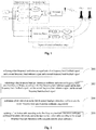
- Figure 1 shows a block diagram of a DPD processing of dual-frequency band in prior art, including a signal extraction and analysis stage, a processing stage and a synthesis stage.
- each length of DPD coefficient c k , j , m 1 and c k , j , m 2 acquired using the above method is as follows:
- C ⁇ c 0,0,0 i c 1,0,0 i c 1,1,0 i ⁇ c i , j ,0 i ... c N , N ,0 i ... c N , N , M ⁇ 1 i T
- the length of the DPD coefficient is M ( K ) K /2. Therefore, the calculation process of the DPD coefficient is very complex, such that it is difficult for the existing system to be realized.
- an embodiment of the present application provides a method for updating multi-frequency band pre-distortion coefficient lookup table.
- Figure 2 shows a flow chart of the method according to the embodiment of the present application.
- the method may particularly include:
- Step 200 collecting a first frequency band reference signal and a first frequency band feedback signal, and a second frequency band reference signal and a second frequency band feedback signal.
- Step 202 calculating a first frequency band pre-distortion coefficient and a second frequency band pre-distortion coefficient, according to the first frequency band reference signal and the first frequency band feedback signal, and the second frequency band reference signal and the second frequency band feedback signal.
- Step 204 performing phase calibration on the first frequency band pre-distortion coefficient and the second frequency band pre-distortion coefficient, respectively.
- Step 206 updating a first lookup table according to the first frequency band pre-distortion coefficient performed the phase calibration, and updating a second lookup table according to the second frequency band pre-distortion coefficient performed the phase calibration.
- the first lookup table is a first frequency band pre-distortion coefficient lookup table
- the second lookup table is a second frequency band pre-distortion coefficient lookup table
- a feedback signal of another frequency band may be introduced, such that the update process of the DPD coefficient lookup table takes into account the interaction of signals of two frequency bands and the calculated DPD coefficient is more accurate.
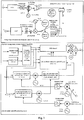
- the overall structure of the multi-frequency band processing will be introduced. As shown in Figure 3 , it may include a first frequency band signal and a second frequency band signal, the frequency bands of which has a difference of 120MHz.
- the upper half of Figure 3 is an analog link section of cross-frequency band DPD processing
- the lower half is a digital processing section of cross-frequency band DPD.
- a synthesis signal Z of the first frequency band and the second frequency band is outputted to an intermediate frequency filter through a Digital to analog converter (DAC), inputted to a quadraphase modulator after filtering, then outputted to a High Power Amplifier (HPA) via the quadraphase modulator, and a radio frequency signal (a signal with frequency band 1 and frequency band 2) is sent out.
- DAC Digital to analog converter
- HPA High Power Amplifier
- the signal outputted from the HPA is coupled to an amplifier coupler in a feedback channel, then splitted into a first frequency band radio frequency signal and a second frequency band radio frequency signal by a power splitter, performed radio frequency analog filtering by a feedback radio frequency filter, respectively; only one of the first frequency band radio frequency signal and the second frequency band radio frequency signal is acquired each time by switch settings; the respectively acquired first frequency band signal and the second frequency band signal subsequently enter a common mixer, an intermediate frequency amplifier and an intermediate frequency feedback anti-aliasing filter, and finally are sent to an ADC for sampling.
- the intermediate frequency amplifier may be regarded as a part of a gain regulator.
- first frequency band radio frequency signal and the second frequency band radio frequency signal are acquired respectively
- a time-sharing collection manner could be employed. That is, the first frequency band signal may be collected first and then the second frequency band signal is collected.
- other collection manners also could be employed, and the embodiment of the present application is not intended to limit thereon.
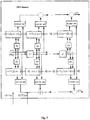
- the process may include:
- the sampled first frequency band signal and second frequency band signal are both down-converted to the base frequency (zero frequency), a low pass filter filters out collected mirror signals by real numbers while retaining effective signals. Since only the first frequency band signal or the second frequency band signal is sampled by the ADC, the single frequency band signal may be filtered and extracted after being down-converted to zero frequency, realizing a restraint on the mirror. Then the filtered signal may be performed a synchronization adjustment and an amplitude alignment calibration, and performed a DPD coefficient calculation and a LUT update processing. During the DPD coefficient calculation and the LUT update processing, the first frequency band signal Z1 and the second frequency band signal Z2 in the DPD channel can be used. At the end, the acquired LUT1 (n) and LUT2 (n) are sent to the DPD channel to perform the DPD processing, and the first frequency band signal Z1 and the second frequency band signal Z2 are superimposed to finally generate an output signal.
- y 1 (n)... y 1 (n-m) is the first frequency band feedback signal
- y 2 (n)... y 2 (n-m) is the second frequency band feedback signal
- z 1 (n) is the first frequency band reference signal
- z 2 (n) is the second frequency band reference signal.
- the first frequency band feedback signal y 1 (n)... y 1 (n-m) and the second frequency band feedback signal y 2 (n)... y 2 (n-m) are performed amplitude adjustment respectively, and then performed pre-distortion parameter training (Adaptive Filtering Algorithm), wherein e (n) is an error signal acquired by comparing z(n) to ⁇ ( n ). The less the error signal is, the more accurate the calculation result is and the better the system performs.
- Adaptive Filtering Algorithm Adaptive Filtering Algorithm
- a DPD coefficient c1 corresponding to the first frequency band signal and a DPD coefficient c2 corresponding to the second frequency band signal can be acquired after training, and then the amplitude
- the LUT1 and the LUT2 acquired through the DPD coefficient calculation and the LUT update processing are inputted to the DPD channel to be processed, while the amplitude
- FIG. 6 shows a flow chart of a method for updating multi-frequency band pre-distortion coefficient lookup table according the embodiment of the present application.
- the method may particularly include:
- Step 600 collecting a first frequency band reference signal and a first frequency band feedback signal, and a second frequency band reference signal and a second frequency band feedback signal.
- the first frequency band reference signal and the first frequency band feedback signal, and the second frequency band reference signal and the second frequency band feedback signal are respectively collected, and during the subsequent calculation of the DPD coefficient of each frequency band, the reference signal and the feedback signal of present frequency band and the feedback signal of another frequency band can be used for calculation.
- Step 602 calculating a first frequency band pre-distortion coefficient and a second frequency band pre-distortion coefficient, according to the first frequency band reference signal and the first frequency band feedback signal, and the second frequency band reference signal and the second frequency band feedback signal.
- the calculation process of the first frequency band pre-distortion coefficient in the Step 602 may particularly include:
- Sub-Step 6021 calculating a first frequency band feedback matrix U 1 , according to the first frequency band feedback signal and the second frequency band feedback signal.
- Sub-Step 6021 may comprise:
- Sub-Step 6022 acquiring a reference matrix z 1 corresponding to the first frequency band reference signal.
- 2 p x 1 (n) is a first frequency band input signal
- x 2 (n) is a second frequency band input signal
- b k,p is a weighting coefficient of interaction between the first frequency band and the second frequency band.
- b k,p is set to a constant, so as to reduce repeated calculation due to different b k,p , simplify the calculation process and reduce the length of DPD coefficient.
- the calculated length of DPD coefficient is relatively long and the calculation complexity is high.
- ⁇ 1 ( n ) U 1 c 1
- ⁇ 1 ( n ) [ z 1 (0),..., z 1 ( N -1)] T .
- the calculation process of the second frequency band pre-distortion coefficient in the Step 602 may particularly include:
- Sub-Step 6024 calculating a second frequency band feedback matrix U 2 , according to the first frequency band feedback signal and the second frequency band feedback signal.
- Sub-Step 6024 may comprise:
- Sub-Step 6025 acquiring a reference matrix z 2 corresponding to the second frequency band reference signal.
- b k,p is also a constant.
- the Sub-Step 6021 to the Sub-Step 6023 is a process of calculating the first frequency band
- the Sub-Step 6024 to the Sub-Step 6026 is a process of calculating the second frequency band
- various steps are not restricted by the sequence, in such a manner that the Sub-Step 6021 to the Sub-Step 6023 can be performed first or the Sub-Step 6024 to the Sub-Step 6026 can be performed first, and the embodiment of the present application is not intended to limit thereon.
- Step 604 performing phase-calibration on the first frequency band pre-distortion coefficient and the second frequency band pre-distortion coefficient, respectively.
- the phase calibration may be further performed on the pre-distortion coefficients.
- the process of performing the phase calibration on the first frequency band pre-distortion coefficient in the Step 604 may particularly include:
- the process of performing the phase calibration on the second frequency band pre-distortion coefficient in the Step 604 may particularly include:
- the Sub-Step 6041 to the Sub-Step 6042 is a process of performing the phase calibration on the first frequency band
- the Sub-Step 6043 to the Sub-Step 6044 is a process of performing the phase calibration on the second frequency band; various steps are not restricted by the sequence, in such a manner that the Sub-Step 6041 to the Sub-Step 6042 can be performed first or the Sub-Step 6043 to the Sub-Step 6044 can be performed first, and the embodiment of the present application is not intended to limit thereon.
- phase of pre-distortion coefficient arithmetic sum for each frequency band is zero, such that the phase of superimposed multi-frequency band signals has no deviation and the pre-distortion calibration of the multi-frequency band signal is more accurate.
- Step 606 updating a first lookup table according to the first frequency band pre-distortion coefficient performed the phase calibration, and updating a second lookup table according to the second frequency band pre-distortion coefficient performed the phase calibration.
- the first lookup table is a first frequency band pre-distortion coefficient lookup table
- the second lookup table is a second frequency band pre-distortion coefficient lookup table
- the process of updating the first lookup table according to the first frequency band pre-distortion coefficient performed the phase calibration may particularly include:
- a quantization factor is further provided for the first lookup table, in order to facilitate the realization of FPGA. Therefore, after generating the first lookup table according to the first frequency band feedback signal and the second frequency band feedback signal, the method may further comprise:
- Sub-Step 6064 of storing the first frequency band pre-distortion coefficient in the first lookup table may comprise:
- the process of updating the second lookup table according to the second frequency band pre-distortion coefficient performed phase calibration in the Step 606 may particularly include:
- a quantization factor is further provided for the second lookup table. Therefore, after generating the second lookup table according to the first frequency band feedback signal and the second frequency band feedback signal, the method may further comprise:
- Sub-Step 6068 of storing the second frequency band pre-distortion coefficient in the second lookup table may comprise:
- the Sub-Step 6061 to the Sub-Step 6064 is a process of updating the first frequency band lookup table
- the Sub-Step 6065 to the Sub-Step 6068 is a process of updating the second frequency band lookup table; various steps are not restricted by the sequence, in such a manner that the Sub-Step 6061 to the Sub-Step 6064 can be performed first or the Sub-Step 6065 to the Sub-Step 6068 can be performed first, and the embodiment of the present application is not intended to limit thereon.
- storage space of the resultant DPD coefficient lookup table has a size of L*L*M.
- the first frequency band as described above may be a F frequency band
- the second frequency band may be an A frequency band; the embodiment of the present application are not intended to limit thereon.
- a feedback signal of another frequency band may be introduced, such that the update process of the DPD coefficient lookup table takes into account the interaction of signals of two frequency bands and the calculated DPD coefficient is more accurate.
- the weighting coefficient b k,p of interaction between the first frequency band and the second frequency band is set to a constant, so as to reduce repeated calculation due to different b k,p in the generation of the DPD coefficient lookup table, simplify the calculation process and reduce the length of DPD coefficient.
- a quantization factor is further provided for the DPD coefficient lookup table, in order to facilitate the realization of FPGA.
- the pre-distortion coefficients are further performed the phase calibration, and then the DPD coefficient lookup tables are updated according to the pre-distortion coefficients performed the phase calibration.
- the phase of the arithmetic sum of the pre-distortion coefficient for each frequency band is zero, such that the phase of superimposed multi-frequency band signals has no deviation when DPD coefficient lookup tables are updated, whereby improving the accuracy of the DPD processing.
- FIG. 7 shows a block diagram of a system for updating multi-frequency band pre-distortion coefficient lookup table according to an embodiment of the present application.
- the system may particularly include: a collection module 10, a calculation module 12, a calibration module 14 and an update module 16.
- the collection module 10 is configured to collect a first frequency band reference signal and a first frequency band feedback signal, and a second frequency band reference signal and a second frequency band feedback signal;
- the calculation module 12 is configured to calculate a first frequency band pre-distortion coefficient and a second frequency band pre-distortion coefficient, according to the first frequency band reference signal and the first frequency band feedback signal, and the second frequency band reference signal and the second frequency band feedback signal.
- the calculation module 12 may particularly comprise:
- a calibration module 14 is configured to perform phase calibration on the first frequency band pre-distortion coefficient and the second frequency band pre-distortion coefficient, respectively;
- the calibration module 14 may particularly include:
- An update module 16 is configured to update a first lookup table according to the first frequency band pre-distortion coefficient performed the phase calibration, and update a second lookup table according to the second frequency band pre-distortion coefficient performed the phase calibration.
- the first lookup table is a first frequency band pre-distortion coefficient lookup table
- the second lookup table is a second frequency band pre-distortion coefficient lookup table
- the update module 16 may include:
- quantization factors of the first lookup table and the second lookup table are provided, and in particular, the update module 16 may further include:
- a feedback signal of another frequency band may be introduced, such that the update process of the DPD coefficient lookup table takes into account the interaction of signals of two frequency bands and the calculated DPD coefficient is more accurate.
- the weighting coefficient b k,p of interaction between the first frequency band and the second frequency band is set to a constant, so as to reduce repeated calculation due to different b k,p in the generation of the DPD coefficient lookup table, simplify the calculation process and reduce the length of DPD coefficient.
- a quantization factor is further provided for the DPD coefficient lookup table, in order to facilitate the realization of FPGA.
- the pre-distortion coefficients are further performed the phase calibration, and then the DPD coefficient lookup tables are updated according to the pre-distortion coefficients performed the phase calibration.
- the phase of the arithmetic sum of the pre-distortion coefficient for each frequency band is zero, such that the phase of superimposed multi-frequency band signals has no deviation when DPD coefficient lookup tables are updated, whereby improving the accuracy of the DPD processing.
- the present application also provides a computer readable recording medium in which a program for executing the method for updating multi-frequency band pre-distortion coefficient lookup table is recorded.
- a program for executing the method for updating multi-frequency band pre-distortion coefficient lookup table is recorded.
- the detailed content of the method for updating multi-frequency band pre-distortion coefficient lookup table could refer to that of the method embodiments, the description of which will be omitted herein.
- the computer readable recording medium may comprise any mechanism for storing or transmitting information in a computing device (e.g., a computer) readable form.
- a computing device e.g., a computer
- the machine readable medium includes Read Only Memory (ROM), Random Access Memory (RAM), magnetic disk storage medium, optical storage medium, flash memory medium, and propagation signals (e.g., carrier wave, infrared signals, digital signals, etc.) in the forms of electrics, optics, acoustics or any other forms.
- the present application can be described in general context of a computer executable instruction which is executed by a computer, such as a program module.
- the program module may include routine, program, object, component, data structure and the like which can perform particular tasks or implement particular abstract data types.
- the present application e can also be practiced in distributed computing environments.
- the program module can be connected to a remote processing device through a communication network to perform the task.
- the program module may be located in local and remote computer storage medium including a memory device.
Landscapes
- Engineering & Computer Science (AREA)
- Power Engineering (AREA)
- Computer Networks & Wireless Communication (AREA)
- Signal Processing (AREA)
- Physics & Mathematics (AREA)
- Nonlinear Science (AREA)
- Spectroscopy & Molecular Physics (AREA)
- Quality & Reliability (AREA)
- Amplifiers (AREA)
Claims (11)
- Verfahren zum Aktualisieren einer Nachschlagetabelle mit Vorverzerrungskoeffizienten für mehrere Frequenzbänder, das umfasst, dass:ein Referenzsignal für ein erstes Frequenzband und ein Rückkopplungssignal für das erste Frequenzband und ein Referenzsignal für ein zweites Frequenzband und ein Rückkopplungssignal für das zweite Frequenzband aufgenommen werden (200, 600);ein Vorverzerrungskoeffizient für das erste Frequenzband und ein Vorverzerrungskoeffizient für das zweite Frequenzband in Übereinstimmung mit dem Referenzsignal für das erste Frequenzband und dem Rückkopplungssignal für das erste Frequenzband und dem Referenzsignal für das zweite Frequenzband und dem Rückkopplungssignal für das zweite Frequenzband berechnet werden (202, 602);dadurch gekennzeichnet, dasseine Phasenkalibrierung jeweils an dem Vorverzerrungskoeffizienten für das erste Frequenzband und an dem Vorverzerrungskoeffizienten für das zweite Frequenzband ausgeführt wird (204, 604);eine erste Nachschlagetabelle in Übereinstimmung mit dem Vorverzerrungskoeffizienten für das erste Frequenzband mit ausgeführter Phasenkalibrierung aktualisiert wird (206, 606), und eine zweite Nachschlagetabelle in Übereinstimmung mit dem Vorverzerrungskoeffizienten für das zweite Frequenzband mit ausgeführter Phasenkalibrierung aktualisiert wird; wobei die erste Nachschlagetabelle eine Nachschlagetabelle mit Vorverzerrungskoeffizienten für das erste Frequenzband ist und die zweite Nachschlagetabelle eine Nachschlagetabelle mit Vorverzerrungskoeffizienten für das zweite Frequenzband ist,
wobeider Schritt des Berechnens des Vorverzerrungskoeffizienten für das erste Frequenzband umfasst, dass:eine Rückkopplungsmatrix U1 für das erste Frequenzband in Übereinstimmung mit dem Rückkopplungssignal für das erste Frequenzband und dem Rückkopplungssignal für das zweite Frequenzband berechnet wird (6021);eine Referenzmatrix z1 beschafft wird (6022), die dem Referenzsignal für das erste Frequenzband entspricht;
eine Matrix ĉ 1, die aus dem Vorverzerrungskoeffizienten für das erste Frequenzband besteht, in Übereinstimmung mit der U1 und der z1 berechnet wird (6023):

 der Schritt des Berechnens des Vorverzerrungskoeffizienten für das zweite Frequenzband umfasst, dass:eine Rückkopplungsmatrix U2 für das zweite Frequenzband in Übereinstimmung mit dem Rückkopplungssignal für das erste Frequenzband und dem Rückkopplungssignal für das zweite Frequenzband berechnet wird (6024);eine Referenzmatrix z2 beschafft wird (6025), die dem Referenzsignal für das zweite Frequenzband entspricht;eine Matrix ĉ 2, die aus dem Vorverzerrungskoeffizienten für das zweite Frequenzband besteht, in Übereinstimmung mit der U2 und der z2 berechnet wird (6026):

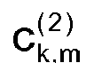
wobeider Schritt des Ausführens der Phasenkalibrierung an dem Vorverzerrungskoeffizienten für das erste Frequenzband umfasst, dass:ein Phasenkalibrierungsfaktor θ(1) für das erste Frequenzband berechnet wird: ein Vorverzerrungskoeffizient
 der Schritt des Ausführens der Phasenkalibrierung an dem Vorverzerrungskoeffizienten für das zweite Frequenzband umfasst, dass:ein Phasenkalibrierungsfaktor θ(2) für das zweite Frequenzband berechnet wird:
 ein Vorverzerrungskoeffizient

- Verfahren nach Anspruch 1, dadurch gekennzeichnet, dass der Schritt des Berechnens der Rückkopplungsmatrix U1 für das erste Frequenzband in Übereinstimmung mit dem Rückkopplungssignal für das erste Frequenzband und dem Rückkopplungssignal für das zweite Frequenzband umfasst, dass:ein Rückkopplungsparameter

 eine transponierte Matrix
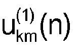
 die Rückkopplungsmatrix U1 für das erste Frequenzband, die aus der

- Verfahren nach Anspruch 1, dadurch gekennzeichnet, dass der Schritt des Berechnens der Rückkopplungsmatrix U2 für das zweite Frequenzband in Übereinstimmung mit dem Rückkopplungssignal für das erste Frequenzband und dem Rückkopplungssignal für das zweite Frequenzband umfasst, dass:ein Rückkopplungsparameter

 eine transponierte Matrix

 die Rückkopplungsmatrix U2 für das zweite Frequenzband, die aus

- Verfahren nach Anspruch 1, dadurch gekennzeichnet, dass der Schritt des Aktualisierens einer ersten Nachschlagetabelle in Übereinstimmung mit dem Vorverzerrungskoeffizienten für das erste Frequenzband mit ausgeführter Phasenkalibrierung umfasst, dass:eine erste Nachschlagetabelle LUT1m(|y1(n-m)|,|y2(-n-m)|), in Übereinstimmung mit dem Rückkopplungssignal für das erste Frequenzband und dem Rückkopplungssignal für das zweite Frequenzband erzeugt wird:
 ein Eingabesignal x1(n) für das erste Frequenzband beschafft wird;eine Amplitude |x1(n-m)| des Eingabesignals für das erste Frequenzband berechnet wird, wenn die Speichertiefe M ist;unter Verwendung der Amplitude |x1(n-m)| des Eingabesignals für das erste Frequenzband als Eingabeadresse der Vorverzerrungskoeffizient für das erste Frequenzband in der ersten Nachschlagetabelle in einer Reihenfolge von Klein zu Groß in Übereinstimmung mit der Eingabeadresse gespeichert wird, um die erste Nachschlagetabelle zu aktualisieren;wobei der Gewichtungskoeffizient bk,p vorzugsweise eine Konstante ist.
 - Verfahren nach Anspruch 4, dadurch gekennzeichnet, dass das Verfahren nach dem Erzeugen der ersten Nachschlagetabelle in Übereinstimmung mit dem Rückkopplungssignal für das erste Frequenzband und dem Rückkopplungssignal für das zweite Frequenzband ferner umfasst, dass:ein Maximalwert mv1 des Eingabesignals für das erste Frequenzband und eine Maximalgröße L1 der ersten Nachschlagetabelle und eine Maximalgröße L2 der zweiten Nachschlagetabelle beschafft werden;der Maximalwert mv1 durch die Maximalgröße L1 dividiert wird und das Berechnungsergebnis als Quantisierungsfaktor Δ1 für das erste Frequenzband verwendet wird;die erste Nachschlagetabelle LUT1m(|y1(n-m)|,|y2(-n-m)|), in Übereinstimmung mit dem Quantisierungsfaktor Δ1 für das erste Frequenzband in LUT1'm(l1Δ1,l2Δ1) transformiert wird:
 der Schritt des Speicherns des Vorverzerrungskoeffizienten für das erste Frequenzband in der ersten Nachschlagetabelle umfasst, dass:der Vorverzerrungskoeffizient für das erste Frequenzband in der transformierten ersten Nachschlagetabelle gespeichert wird.
 - Verfahren nach Anspruch 1, dadurch gekennzeichnet, dass der Schritt des Aktualisierens einer zweiten Nachschlagetabelle in Übereinstimmung mit dem Vorverzerrungskoeffizienten für das zweite Frequenzband mit ausgeführter Phasenkalibrierung umfasst, dass:eine zweite Nachschlagetabelle LUT2m(|y2(n-m)|,|y1(-n-m)|), in Übereinstimmung mit dem Rückkopplungssignal für das erste Frequenzband und dem Rückkopplungssignal für das zweite Frequenzband erzeugt wird, wobei
 ein Eingabesignal x2(n) für das zweite Frequenzband beschafft wird;eine Amplitude |x2(n-m)| des Eingabesignals für das zweite Frequenzband berechnet wird, wenn die Speichertiefe M ist;unter Verwendung der Amplitude |x2(n-m)| des Eingabesignals für das zweite Frequenzband als Eingabeadresse der Vorverzerrungskoeffizient für das zweite Frequenzband in der zweiten Nachschlagetabelle in einer Reihenfolge von Klein zu Groß in Übereinstimmung mit der Eingabeadresse gespeichert wird, um die zweite Nachschlagetabelle zu aktualisieren;wobei der Gewichtungskoeffizient bk,p vorzugsweise eine Konstante ist.
 - Verfahren nach Anspruch 6, dadurch gekennzeichnet, dass das Verfahren nach dem Erzeugen der zweiten Nachschlagetabelle in Übereinstimmung mit dem Rückkopplungssignal für das erste Frequenzband und dem Rückkopplungssignal für das zweite Frequenzband ferner umfasst, dass:ein Maximalwert mv2 des Eingabesignals für das zweite Frequenzband und eine Maximalgröße L2 der zweiten Nachschlagetabelle und eine Maximalgröße L1 der ersten Nachschlagetabelle beschafft werden;der Maximalwert mv2 durch die Maximalgröße L2 dividiert wird und das berechnete Ergebnis als Quantisierungsfaktor Δ2 für das zweite Frequenzband verwendet wird;die zweite Nachschlagetabelle LUT2m(|y2(n-m)|,|y1(-n-m)|), in Übereinstimmung mit dem Quantisierungsfaktor Δ2 für das zweite Frequenzband in LUT2'm(l2Δ2,l1Δ2) transformiert wird, wobei:
 wobei der Schritt des Speicherns des Vorverzerrungskoeffizienten für das zweite Frequenzband in der zweiten Nachschlagetabelle umfasst, dass:der Vorverzerrungskoeffizient für das zweite Frequenzband in der transformierten zweiten Nachschlagetabelle gespeichert wird.
 - System zum Aktualisieren einer Nachschlagetabelle mit Vorverzerrungskoeffizienten für mehrere Frequenzbänder, das umfasst:ein Aufnahmemodul (10), das ausgestaltet ist, um ein Referenzsignal für ein erstes Frequenzband und ein Rückkopplungssignal für das erste Frequenzband und ein Referenzsignal für ein zweites Frequenzband und ein Rückkopplungssignal für das zweite Frequenzband aufzunehmen;ein Berechnungsmodul (12), das ausgestaltet ist, um einen Vorverzerrungskoeffizienten für das erste Frequenzband und einen Vorverzerrungskoeffizienten für das zweite Frequenzband in Übereinstimmung mit dem Referenzsignal für das erste Frequenzband und dem Rückkopplungssignal für das erste Frequenzband und dem Referenzsignal für das zweite Frequenzband und dem Rückkopplungssignal für das zweite Frequenzband zu berechnen;gekennzeichnet durchein Kalibrierungsmodul (14), das ausgestaltet ist, um eine Phasenkalibrierung jeweils an dem Vorverzerrungskoeffizienten für das erste Frequenzband und an dem Vorverzerrungskoeffizienten für das zweite Frequenzband auszuführen;ein Aktualisierungsmodul (16), das ausgestaltet ist, um eine erste Nachschlagetabelle in Übereinstimmung mit dem Vorverzerrungskoeffizienten für das erste Frequenzband mit ausgeführter Phasenkalibrierung zu aktualisieren, und um eine zweite Nachschlagetabelle in Übereinstimmung mit dem Vorverzerrungskoeffizienten für das zweite Frequenzband mit ausgeführter Phasenkalibrierung zu aktualisieren; wobei die erste Nachschlagetabelle eine Nachschlagetabelle mit Vorverzerrungskoeffizienten für das erste Frequenzband ist und die zweite Nachschlagetabelle eine Nachschlagetabelle mit Vorverzerrungskoeffizienten für das zweite Frequenzband ist, wobeidas Berechnungsmodul (12) umfasst:ein erstes Matrixberechnungsmodul, das ausgestaltet ist, um eine Rückkopplungsmatrix U1 für das erste Frequenzband in Übereinstimmung mit dem Rückkopplungssignal für das erste Frequenzband und dem Rückkopplungssignal für das zweite Frequenzband zu berechnen;ein erstes Beschaffungsmodul, das ausgestaltet ist, um eine Referenzmatrix z1 zu beschaffen, die dem Referenzsignal für das erste Frequenzband entspricht;ein erstes Koeffizientenberechnungsmodul, das ausgestaltet ist, um eine Matrix ĉ 1, die aus dem Vorverzerrungskoeffizienten für das erste Frequenzband besteht, in Übereinstimmung mit der U1 und der z1 zu berechnen:


 ein zweites Matrixberechnungsmodul, das ausgestaltet ist, um eine Rückkopplungsmatrix U2 für das zweite Frequenzband in Übereinstimmung mit dem Rückkopplungssignal für das erste Frequenzband und dem Rückkopplungssignal für das zweite Frequenzband zu berechnen;ein zweites Beschaffungsmodul, das ausgestaltet ist, um eine Referenzmatrix z2 zu beschaffen, die dem Referenzsignal für das zweite Frequenzband entspricht;ein zweites Koeffizientenberechnungsmodul, das ausgestaltet ist, um eine Matrix ĉ 2, die aus dem Vorverzerrungskoeffizienten für das zweite Frequenzband besteht, in Übereinstimmung mit der U2 und der z2 zu berechnen:


wobeidas Kalibrierungsmodul (14) umfasst:ein Modul zum Berechnen eines ersten Kalibrierungsfaktors, das ausgestaltet ist, um einen Phasenkalibrierungsfaktor θ(1) für das erste Frequenzband zu berechnen: ein erstes Kalibrierungsmodul, das ausgestaltet ist, um einen Vorverzerrungskoeffizienten
 ein Modul zum Berechnen eines zweiten Kalibrierungsfaktors, das ausgestaltet ist, um einen Phasenkalibrierungsfaktor θ(2) für das zweite Frequenzband zu berechnen:
 ein zweites Kalibrierungsmodul, das ausgestaltet ist, um einen Vorverzerrungskoeffizienten

- System nach Anspruch 8, dadurch gekennzeichnet, dass das erste Matrixberechnungsmodul umfasst:eine Teileinheit zum Berechnen einer ersten Referenz, die ausgestaltet ist, um einen Rückkopplungsparameter

 eine Teileinheit zum Berechnen einer ersten transponierten Matrix, die ausgestaltet ist, um eine transponierte Matrix

 eine Teileinheit zum Berechnen einer ersten Rückkopplungsmatrix, die ausgestaltet ist, um eine Rückkopplungsmatrix U1, die aus
 das zweite Matrixberechnungsmodul umfasst:eine Teileinheit zum Berechnen einer zweiten Referenz, die ausgestaltet ist, um einen Rückkopplungsparameter
 eine Teileinheit zum Berechnen einer zweiten transponierten Matrix, die ausgestaltet ist, um eine transponierte Matrix

 eine Teileinheit zum Berechnen einer zweiten Rückkopplungsmatrix, die ausgestaltet ist, um die Rückkopplungsmatrix U2 für das zweite Frequenzband, die aus

- Verfahren nach Anspruch 8, dadurch gekennzeichnet, dass das Aktualisierungsmodul (16) umfasst:ein erstes Erzeugungsmodul, das ausgestaltet ist, um eine erste Nachschlagetabelle LUT1m(|y1(n-m)|,|y2(n-m)|), in Übereinstimmung mit dem Rückkopplungssignal für das erste Frequenzband und dem Rückkopplungssignal für das zweite Frequenzband zu erzeugen:
 ein Modul zum Beschaffen eines ersten Eingabesignals, das ausgestaltet ist, um ein Eingabesignal x1(n) für das erste Frequenzband zu beschaffen;ein Modul zum Berechnen einer ersten Amplitude, das ausgestaltet ist, um eine Amplitude |x1(n-m)| des Eingabesignals für das erste Frequenzband zu berechnen, wenn die Speichertiefe M ist;ein erstes Aktualisierungsmodul, das ausgestaltet ist, um unter Verwendung der Amplitude |x1(n-m)| des Eingabesignals für das erste Frequenzband als Eingabeadresse den Vorverzerrungskoeffizienten für das erste Frequenzband in der ersten Nachschlagetabelle in einer Reihenfolge von Klein zu Groß in Übereinstimmung mit der Eingabeadresse zu speichern, um die erste Nachschlagetabelle zu aktualisieren;ein zweites Erzeugungsmodul, das ausgestaltet ist, um eine zweite Nachschlagetabelle LUT2m(|y2(n-m)|,|y1(-n-m)|), in Übereinstimmung mit dem Rückkopplungssignal für das erste Frequenzband und mit dem Rückkopplungssignal für das zweite Frequenzband zu erzeugen, wobei
 ein Modul zum Beschaffen eines zweiten Eingabesignals, das ausgestaltet ist, um ein Eingabesignal x2(n) für das zweite Frequenzband zu beschaffen;ein Modul zum Berechnen einer zweiten Amplitude, das ausgestaltet ist, um eine Amplitude |x2(n-m)| des Eingabesignals für das zweite Frequenzband zu berechnen, wenn die Speichertiefe M ist;ein zweites Aktualisierungsmodul, das ausgestaltet ist, um unter Verwendung der Amplitude |x2(n-m)| des Eingabesignals für das zweite Frequenzband als Eingabeadresse den Vorverzerrungskoeffizienten für das zweite Frequenzband in der zweiten Nachschlagetabelle in einer Reihenfolge von Klein zu Groß in Übereinstimmung mit der Eingabeadresse zu speichern, um die zweite Nachschlagetabelle zu aktualisieren;wobei der Gewichtungskoeffizient bk,p vorzugsweise eine Konstante ist.
 - Computerprogrammprodukt, das Anweisungen umfasst, welche, wenn sie auf einer Rechenvorrichtung ausgeführt werden, veranlassen, dass die Rechenvorrichtung alle Verfahrensschritte in Übereinstimmung mit beliebigen der Ansprüche 1 bis 7 ausführt.
Applications Claiming Priority (2)
| Application Number | Priority Date | Filing Date | Title |
|---|---|---|---|
| CN201210487334.7A CN103023842B (zh) | 2012-11-26 | 2012-11-26 | 一种多频段预失真系数查找表更新方法和系统 |
| PCT/CN2013/079532 WO2014079222A1 (zh) | 2012-11-26 | 2013-07-17 | 一种多频段预失真系数查找表更新方法和系统 |
Publications (3)
| Publication Number | Publication Date |
|---|---|
| EP2924938A1 EP2924938A1 (de) | 2015-09-30 |
| EP2924938A4 EP2924938A4 (de) | 2016-08-17 |
| EP2924938B1 true EP2924938B1 (de) | 2018-04-04 |
Family
ID=47971980
Family Applications (1)
| Application Number | Title | Priority Date | Filing Date |
|---|---|---|---|
| EP13857235.9A Active EP2924938B1 (de) | 2012-11-26 | 2013-07-17 | Verfahren und system zur aktualisierung einer mehrfrequenzband-vorverzerrungskoeffizientennachschlagtabelle |
Country Status (4)
| Country | Link |
|---|---|
| US (1) | US9231733B2 (de) |
| EP (1) | EP2924938B1 (de) |
| CN (1) | CN103023842B (de) |
| WO (1) | WO2014079222A1 (de) |
Families Citing this family (24)
| Publication number | Priority date | Publication date | Assignee | Title |
|---|---|---|---|---|
| CN103023842B (zh) * | 2012-11-26 | 2016-08-24 | 大唐移动通信设备有限公司 | 一种多频段预失真系数查找表更新方法和系统 |
| TWI536731B (zh) * | 2013-08-20 | 2016-06-01 | 瑞昱半導體股份有限公司 | 預失真方法、預失真裝置以及機器可讀媒體 |
| CN105763495B (zh) * | 2014-12-16 | 2020-01-31 | 中兴通讯股份有限公司 | 一种数字预失真的方法和装置 |
| US10324169B2 (en) * | 2015-04-06 | 2019-06-18 | The United States Of America As Represented By The Secretary Of The Navy. | Digital compensation for amplifier-induced instability |
| CN104869091A (zh) * | 2015-04-29 | 2015-08-26 | 大唐移动通信设备有限公司 | 一种数字预失真系数训练方法及系统 |
| CN104901914B (zh) * | 2015-05-14 | 2018-11-02 | 大唐移动通信设备有限公司 | 一种多频段联合预失真的处理方法和装置 |
| CN105024960B (zh) * | 2015-06-23 | 2018-11-09 | 大唐移动通信设备有限公司 | 一种dpd系统 |
| CN104980174B (zh) * | 2015-06-30 | 2018-02-06 | 上海华为技术有限公司 | 一种双频段双输入功放发射机 |
| US10338594B2 (en) | 2017-03-13 | 2019-07-02 | Nio Usa, Inc. | Navigation of autonomous vehicles to enhance safety under one or more fault conditions |
| CN107104746B (zh) * | 2017-04-26 | 2021-02-26 | 中国人民解放军国防科技大学 | 跳频电台发信机非线性特性建模方法 |
| US10423162B2 (en) | 2017-05-08 | 2019-09-24 | Nio Usa, Inc. | Autonomous vehicle logic to identify permissioned parking relative to multiple classes of restricted parking |
| US10710633B2 (en) | 2017-07-14 | 2020-07-14 | Nio Usa, Inc. | Control of complex parking maneuvers and autonomous fuel replenishment of driverless vehicles |
| US10369974B2 (en) | 2017-07-14 | 2019-08-06 | Nio Usa, Inc. | Control and coordination of driverless fuel replenishment for autonomous vehicles |
| CN107835140B (zh) * | 2017-10-24 | 2019-11-12 | 东南大学 | 共发双带功率放大器的数字预失真系统及其方法 |
| CN108900207B (zh) * | 2018-08-29 | 2020-03-13 | 京信通信系统(中国)有限公司 | 功放装置、射频信号处理系统和基站 |
| US11113176B2 (en) | 2019-01-14 | 2021-09-07 | Microsoft Technology Licensing, Llc | Generating a debugging network for a synchronous digital circuit during compilation of program source code |
| US11144286B2 (en) | 2019-01-14 | 2021-10-12 | Microsoft Technology Licensing, Llc | Generating synchronous digital circuits from source code constructs that map to circuit implementations |
| US11106437B2 (en) * | 2019-01-14 | 2021-08-31 | Microsoft Technology Licensing, Llc | Lookup table optimization for programming languages that target synchronous digital circuits |
| US11093682B2 (en) | 2019-01-14 | 2021-08-17 | Microsoft Technology Licensing, Llc | Language and compiler that generate synchronous digital circuits that maintain thread execution order |
| US11275568B2 (en) | 2019-01-14 | 2022-03-15 | Microsoft Technology Licensing, Llc | Generating a synchronous digital circuit from a source code construct defining a function call |
| WO2020227905A1 (zh) * | 2019-05-13 | 2020-11-19 | 华为技术有限公司 | 预失真参数更新装置及方法、预失真处理系统 |
| CN113127695B (zh) * | 2020-01-16 | 2024-04-12 | 大唐移动通信设备有限公司 | 一种查找表lut的更新方法及装置 |
| US11245428B2 (en) * | 2020-03-12 | 2022-02-08 | Qualcomm Incorporated | Digital predistortion training procedure for massive array |
| US20250274881A1 (en) * | 2024-02-23 | 2025-08-28 | Samsung Electronics Company, Ltd. | Systems and Methods for Event Triggered Timing Mismatch Calibration in Distributed MIMO Using Historical Measurements |
Family Cites Families (16)
| Publication number | Priority date | Publication date | Assignee | Title |
|---|---|---|---|---|
| KR100480278B1 (ko) * | 2002-12-24 | 2005-04-07 | 삼성전자주식회사 | 광대역 전력 증폭기를 위한 디지털 전치보상기 및 그적응화 방법 |
| US7183847B2 (en) * | 2004-01-28 | 2007-02-27 | Ntt Docomo, Inc. | Multi-band look-up table type predistorter |
| DE102004005130B3 (de) * | 2004-02-02 | 2005-04-14 | Infineon Technologies Ag | Sende-/Empfangsanordnung und Verfahren zur Reduktion von Nichtlinearitäten in Ausgangssignalen einer Sende-/Empfangsanordnung |
| US8081710B2 (en) * | 2007-11-08 | 2011-12-20 | Pine Valley Investments, Inc. | System and method for corrected modulation with nonlinear power amplification |
| US9397396B2 (en) * | 2009-04-01 | 2016-07-19 | Kathrein-Werke Kg | Radio system and a method for relaying packetized radio signals |
| CN102461057B (zh) * | 2009-05-07 | 2015-04-08 | 法国电信公司 | 使用频分双工时间反演的预均衡方法 |
| CN102082752B (zh) * | 2010-02-25 | 2014-03-19 | 电信科学技术研究院 | 一种数字预失真处理方法及设备 |
| US8615208B2 (en) * | 2010-11-02 | 2013-12-24 | Crestcom, Inc. | Transmitter linearized in response to signal magnitude derivative parameter and method therefor |
| CN102014090B (zh) * | 2010-12-13 | 2015-05-13 | 中兴通讯股份有限公司 | 数字预失真方法及装置 |
| JP5707999B2 (ja) * | 2011-02-09 | 2015-04-30 | 富士通株式会社 | 歪補償装置、送信機及び歪補償方法 |
| CN102255835B (zh) * | 2011-07-11 | 2015-03-11 | 电信科学技术研究院 | 多频段宽带dpd查找表生成方法、dpd处理方法和系统 |
| US8503950B1 (en) * | 2011-08-02 | 2013-08-06 | Xilinx, Inc. | Circuit and method for crest factor reduction |
| CN102299878B (zh) * | 2011-09-06 | 2014-03-19 | 电信科学技术研究院 | 一种多频段dpd的实现方法及装置 |
| US8576942B2 (en) * | 2011-09-07 | 2013-11-05 | Panasonic Corporation | High efficiency transmitter |
| CN103023842B (zh) * | 2012-11-26 | 2016-08-24 | 大唐移动通信设备有限公司 | 一种多频段预失真系数查找表更新方法和系统 |
| JP2015142325A (ja) * | 2014-01-30 | 2015-08-03 | 富士通株式会社 | 歪補償装置および歪補償方法 |
-
2012
- 2012-11-26 CN CN201210487334.7A patent/CN103023842B/zh active Active
-
2013
- 2013-07-17 EP EP13857235.9A patent/EP2924938B1/de active Active
- 2013-07-17 WO PCT/CN2013/079532 patent/WO2014079222A1/zh not_active Ceased
- 2013-07-17 US US14/646,733 patent/US9231733B2/en active Active
Non-Patent Citations (1)
| Title |
|---|
| None * |
Also Published As
| Publication number | Publication date |
|---|---|
| EP2924938A4 (de) | 2016-08-17 |
| WO2014079222A1 (zh) | 2014-05-30 |
| CN103023842B (zh) | 2016-08-24 |
| US20150304068A1 (en) | 2015-10-22 |
| US9231733B2 (en) | 2016-01-05 |
| CN103023842A (zh) | 2013-04-03 |
| EP2924938A1 (de) | 2015-09-30 |
Similar Documents
| Publication | Publication Date | Title |
|---|---|---|
| EP2924938A1 (de) | Verfahren und system zur aktualisierung einer mehrfrequenzband-vorverzerrungskoeffizientennachschlagtabelle | |
| CN105556860B (zh) | 用于非线性数字自干扰消除的系统以及方法 | |
| KR100740356B1 (ko) | 진폭 재구성 증폭기를 위한 폐쇄 루프 보정 | |
| US11476809B2 (en) | Polyphase digital signal predistortion in radio transmitter | |
| EP2690787B1 (de) | Fehlanpassungskorrektur eines Zeitverschachtelten Analog-Digital-Wandlers | |
| EP3208938B1 (de) | Vorrichtung und verfahren zur vorverzerrungsverarbeitung | |
| US9647717B2 (en) | Digital pre-distortion parameter obtaining method and pre-distortion system | |
| US10735013B2 (en) | Linear and non-linear calibration for time interleaved digital-to-analog converter | |
| US7415252B2 (en) | Arrangement and method for digital predistortion of a complex baseband input signal | |
| US9385764B2 (en) | Digital pre-distortion for high bandwidth signals | |
| CN103493367A (zh) | 进行预失真的方法和预失真器 | |
| KR20110131299A (ko) | I/q 불균형 보상 방법 및 장치 | |
| EP2755358B1 (de) | Verfahren und vorrichtung zur erfassung von ausgangssignalen mit digitaler vorverzerrung in einem mehrfrequenzband | |
| CN101902258A (zh) | 一种数字预失真处理参数求取的方法及装置 | |
| WO2019018739A1 (en) | COMPACT MODEL NON-LINEAR COMPENSATION OF LIMITED BAND RECEIVER SYSTEMS | |
| CN104639481B (zh) | 一种多频段信号处理方法及设备 | |
| US7693672B2 (en) | Adaptive self-linearization | |
| US20210111707A1 (en) | Digital interpolation filter, corresponding rhythm changing device and receiving equipment | |
| JP2016034121A (ja) | 送信機 | |
| KR102097521B1 (ko) | 고주파 증폭 장치 및 왜곡보상 방법 | |
| EP2897334B1 (de) | Adaptives filterverfahren und system auf der basis von subbandfehlen | |
| EP4113830B1 (de) | Amplituden-/phasenregler, amplituden-/phasenregelungsverfahren, verstärkungsvorrichtung und funksender | |
| CN106341102B (zh) | 一种用于宽带系统的数字式相位非线性校正方法及装置 | |
| CN120415970B (zh) | 一种信号预失真处理方法、装置、电子设备及存储介质 | |
| US20190013828A1 (en) | Method and system for improving spurious free dynamic range of signal processing systems |
Legal Events
| Date | Code | Title | Description |
|---|---|---|---|
| PUAI | Public reference made under article 153(3) epc to a published international application that has entered the european phase |
Free format text: ORIGINAL CODE: 0009012 |
|
| 17P | Request for examination filed |
Effective date: 20150618 |
|
| AK | Designated contracting states |
Kind code of ref document: A1 Designated state(s): AL AT BE BG CH CY CZ DE DK EE ES FI FR GB GR HR HU IE IS IT LI LT LU LV MC MK MT NL NO PL PT RO RS SE SI SK SM TR |
|
| AX | Request for extension of the european patent |
Extension state: BA ME |
|
| DAX | Request for extension of the european patent (deleted) | ||
| RA4 | Supplementary search report drawn up and despatched (corrected) |
Effective date: 20160718 |
|
| RIC1 | Information provided on ipc code assigned before grant |
Ipc: H04L 25/49 20060101AFI20160712BHEP |
|
| GRAP | Despatch of communication of intention to grant a patent |
Free format text: ORIGINAL CODE: EPIDOSNIGR1 |
|
| STAA | Information on the status of an ep patent application or granted ep patent |
Free format text: STATUS: GRANT OF PATENT IS INTENDED |
|
| INTG | Intention to grant announced |
Effective date: 20180104 |
|
| GRAS | Grant fee paid |
Free format text: ORIGINAL CODE: EPIDOSNIGR3 |
|
| GRAA | (expected) grant |
Free format text: ORIGINAL CODE: 0009210 |
|
| STAA | Information on the status of an ep patent application or granted ep patent |
Free format text: STATUS: THE PATENT HAS BEEN GRANTED |
|
| AK | Designated contracting states |
Kind code of ref document: B1 Designated state(s): AL AT BE BG CH CY CZ DE DK EE ES FI FR GB GR HR HU IE IS IT LI LT LU LV MC MK MT NL NO PL PT RO RS SE SI SK SM TR |
|
| REG | Reference to a national code |
Ref country code: GB Ref legal event code: FG4D |
|
| REG | Reference to a national code |
Ref country code: CH Ref legal event code: EP |
|
| REG | Reference to a national code |
Ref country code: AT Ref legal event code: REF Ref document number: 986745 Country of ref document: AT Kind code of ref document: T Effective date: 20180415 |
|
| REG | Reference to a national code |
Ref country code: IE Ref legal event code: FG4D |
|
| REG | Reference to a national code |
Ref country code: DE Ref legal event code: R096 Ref document number: 602013035540 Country of ref document: DE |
|
| REG | Reference to a national code |
Ref country code: FR Ref legal event code: PLFP Year of fee payment: 6 |
|
| REG | Reference to a national code |
Ref country code: NL Ref legal event code: MP Effective date: 20180404 |
|
| REG | Reference to a national code |
Ref country code: LT Ref legal event code: MG4D |
|
| PG25 | Lapsed in a contracting state [announced via postgrant information from national office to epo] |
Ref country code: NL Free format text: LAPSE BECAUSE OF FAILURE TO SUBMIT A TRANSLATION OF THE DESCRIPTION OR TO PAY THE FEE WITHIN THE PRESCRIBED TIME-LIMIT Effective date: 20180404 |
|
| PG25 | Lapsed in a contracting state [announced via postgrant information from national office to epo] |
Ref country code: BG Free format text: LAPSE BECAUSE OF FAILURE TO SUBMIT A TRANSLATION OF THE DESCRIPTION OR TO PAY THE FEE WITHIN THE PRESCRIBED TIME-LIMIT Effective date: 20180704 Ref country code: ES Free format text: LAPSE BECAUSE OF FAILURE TO SUBMIT A TRANSLATION OF THE DESCRIPTION OR TO PAY THE FEE WITHIN THE PRESCRIBED TIME-LIMIT Effective date: 20180404 Ref country code: LT Free format text: LAPSE BECAUSE OF FAILURE TO SUBMIT A TRANSLATION OF THE DESCRIPTION OR TO PAY THE FEE WITHIN THE PRESCRIBED TIME-LIMIT Effective date: 20180404 Ref country code: PL Free format text: LAPSE BECAUSE OF FAILURE TO SUBMIT A TRANSLATION OF THE DESCRIPTION OR TO PAY THE FEE WITHIN THE PRESCRIBED TIME-LIMIT Effective date: 20180404 Ref country code: NO Free format text: LAPSE BECAUSE OF FAILURE TO SUBMIT A TRANSLATION OF THE DESCRIPTION OR TO PAY THE FEE WITHIN THE PRESCRIBED TIME-LIMIT Effective date: 20180704 Ref country code: FI Free format text: LAPSE BECAUSE OF FAILURE TO SUBMIT A TRANSLATION OF THE DESCRIPTION OR TO PAY THE FEE WITHIN THE PRESCRIBED TIME-LIMIT Effective date: 20180404 Ref country code: SE Free format text: LAPSE BECAUSE OF FAILURE TO SUBMIT A TRANSLATION OF THE DESCRIPTION OR TO PAY THE FEE WITHIN THE PRESCRIBED TIME-LIMIT Effective date: 20180404 Ref country code: AL Free format text: LAPSE BECAUSE OF FAILURE TO SUBMIT A TRANSLATION OF THE DESCRIPTION OR TO PAY THE FEE WITHIN THE PRESCRIBED TIME-LIMIT Effective date: 20180404 |
|
| PG25 | Lapsed in a contracting state [announced via postgrant information from national office to epo] |
Ref country code: RS Free format text: LAPSE BECAUSE OF FAILURE TO SUBMIT A TRANSLATION OF THE DESCRIPTION OR TO PAY THE FEE WITHIN THE PRESCRIBED TIME-LIMIT Effective date: 20180404 Ref country code: GR Free format text: LAPSE BECAUSE OF FAILURE TO SUBMIT A TRANSLATION OF THE DESCRIPTION OR TO PAY THE FEE WITHIN THE PRESCRIBED TIME-LIMIT Effective date: 20180705 Ref country code: HR Free format text: LAPSE BECAUSE OF FAILURE TO SUBMIT A TRANSLATION OF THE DESCRIPTION OR TO PAY THE FEE WITHIN THE PRESCRIBED TIME-LIMIT Effective date: 20180404 Ref country code: LV Free format text: LAPSE BECAUSE OF FAILURE TO SUBMIT A TRANSLATION OF THE DESCRIPTION OR TO PAY THE FEE WITHIN THE PRESCRIBED TIME-LIMIT Effective date: 20180404 |
|
| REG | Reference to a national code |
Ref country code: AT Ref legal event code: MK05 Ref document number: 986745 Country of ref document: AT Kind code of ref document: T Effective date: 20180404 |
|
| PG25 | Lapsed in a contracting state [announced via postgrant information from national office to epo] |
Ref country code: PT Free format text: LAPSE BECAUSE OF FAILURE TO SUBMIT A TRANSLATION OF THE DESCRIPTION OR TO PAY THE FEE WITHIN THE PRESCRIBED TIME-LIMIT Effective date: 20180806 |
|
| REG | Reference to a national code |
Ref country code: DE Ref legal event code: R097 Ref document number: 602013035540 Country of ref document: DE |
|
| PG25 | Lapsed in a contracting state [announced via postgrant information from national office to epo] |
Ref country code: SK Free format text: LAPSE BECAUSE OF FAILURE TO SUBMIT A TRANSLATION OF THE DESCRIPTION OR TO PAY THE FEE WITHIN THE PRESCRIBED TIME-LIMIT Effective date: 20180404 Ref country code: RO Free format text: LAPSE BECAUSE OF FAILURE TO SUBMIT A TRANSLATION OF THE DESCRIPTION OR TO PAY THE FEE WITHIN THE PRESCRIBED TIME-LIMIT Effective date: 20180404 Ref country code: CZ Free format text: LAPSE BECAUSE OF FAILURE TO SUBMIT A TRANSLATION OF THE DESCRIPTION OR TO PAY THE FEE WITHIN THE PRESCRIBED TIME-LIMIT Effective date: 20180404 Ref country code: DK Free format text: LAPSE BECAUSE OF FAILURE TO SUBMIT A TRANSLATION OF THE DESCRIPTION OR TO PAY THE FEE WITHIN THE PRESCRIBED TIME-LIMIT Effective date: 20180404 Ref country code: EE Free format text: LAPSE BECAUSE OF FAILURE TO SUBMIT A TRANSLATION OF THE DESCRIPTION OR TO PAY THE FEE WITHIN THE PRESCRIBED TIME-LIMIT Effective date: 20180404 Ref country code: AT Free format text: LAPSE BECAUSE OF FAILURE TO SUBMIT A TRANSLATION OF THE DESCRIPTION OR TO PAY THE FEE WITHIN THE PRESCRIBED TIME-LIMIT Effective date: 20180404 |
|
| PLBE | No opposition filed within time limit |
Free format text: ORIGINAL CODE: 0009261 |
|
| STAA | Information on the status of an ep patent application or granted ep patent |
Free format text: STATUS: NO OPPOSITION FILED WITHIN TIME LIMIT |
|
| PG25 | Lapsed in a contracting state [announced via postgrant information from national office to epo] |
Ref country code: SM Free format text: LAPSE BECAUSE OF FAILURE TO SUBMIT A TRANSLATION OF THE DESCRIPTION OR TO PAY THE FEE WITHIN THE PRESCRIBED TIME-LIMIT Effective date: 20180404 Ref country code: IT Free format text: LAPSE BECAUSE OF FAILURE TO SUBMIT A TRANSLATION OF THE DESCRIPTION OR TO PAY THE FEE WITHIN THE PRESCRIBED TIME-LIMIT Effective date: 20180404 |
|
| REG | Reference to a national code |
Ref country code: CH Ref legal event code: PL |
|
| 26N | No opposition filed |
Effective date: 20190107 |
|
| PG25 | Lapsed in a contracting state [announced via postgrant information from national office to epo] |
Ref country code: MC Free format text: LAPSE BECAUSE OF FAILURE TO SUBMIT A TRANSLATION OF THE DESCRIPTION OR TO PAY THE FEE WITHIN THE PRESCRIBED TIME-LIMIT Effective date: 20180404 Ref country code: LU Free format text: LAPSE BECAUSE OF NON-PAYMENT OF DUE FEES Effective date: 20180717 |
|
| REG | Reference to a national code |
Ref country code: IE Ref legal event code: MM4A |
|
| PG25 | Lapsed in a contracting state [announced via postgrant information from national office to epo] |
Ref country code: LI Free format text: LAPSE BECAUSE OF NON-PAYMENT OF DUE FEES Effective date: 20180731 Ref country code: CH Free format text: LAPSE BECAUSE OF NON-PAYMENT OF DUE FEES Effective date: 20180731 Ref country code: IE Free format text: LAPSE BECAUSE OF NON-PAYMENT OF DUE FEES Effective date: 20180717 |
|
| PG25 | Lapsed in a contracting state [announced via postgrant information from national office to epo] |
Ref country code: SI Free format text: LAPSE BECAUSE OF FAILURE TO SUBMIT A TRANSLATION OF THE DESCRIPTION OR TO PAY THE FEE WITHIN THE PRESCRIBED TIME-LIMIT Effective date: 20180404 |
|
| PG25 | Lapsed in a contracting state [announced via postgrant information from national office to epo] |
Ref country code: MT Free format text: LAPSE BECAUSE OF NON-PAYMENT OF DUE FEES Effective date: 20180717 |
|
| PG25 | Lapsed in a contracting state [announced via postgrant information from national office to epo] |
Ref country code: TR Free format text: LAPSE BECAUSE OF FAILURE TO SUBMIT A TRANSLATION OF THE DESCRIPTION OR TO PAY THE FEE WITHIN THE PRESCRIBED TIME-LIMIT Effective date: 20180404 |
|
| PG25 | Lapsed in a contracting state [announced via postgrant information from national office to epo] |
Ref country code: HU Free format text: LAPSE BECAUSE OF FAILURE TO SUBMIT A TRANSLATION OF THE DESCRIPTION OR TO PAY THE FEE WITHIN THE PRESCRIBED TIME-LIMIT; INVALID AB INITIO Effective date: 20130717 Ref country code: CY Free format text: LAPSE BECAUSE OF FAILURE TO SUBMIT A TRANSLATION OF THE DESCRIPTION OR TO PAY THE FEE WITHIN THE PRESCRIBED TIME-LIMIT Effective date: 20180404 Ref country code: MK Free format text: LAPSE BECAUSE OF NON-PAYMENT OF DUE FEES Effective date: 20180404 |
|
| PG25 | Lapsed in a contracting state [announced via postgrant information from national office to epo] |
Ref country code: IS Free format text: LAPSE BECAUSE OF FAILURE TO SUBMIT A TRANSLATION OF THE DESCRIPTION OR TO PAY THE FEE WITHIN THE PRESCRIBED TIME-LIMIT Effective date: 20180804 |
|
| PGFP | Annual fee paid to national office [announced via postgrant information from national office to epo] |
Ref country code: DE Payment date: 20250722 Year of fee payment: 13 |
|
| PGFP | Annual fee paid to national office [announced via postgrant information from national office to epo] |
Ref country code: GB Payment date: 20250722 Year of fee payment: 13 Ref country code: BE Payment date: 20250718 Year of fee payment: 13 |
|
| PGFP | Annual fee paid to national office [announced via postgrant information from national office to epo] |
Ref country code: FR Payment date: 20250725 Year of fee payment: 13 |