EP2924413A1 - Engine component testing device - Google Patents
Engine component testing device Download PDFInfo
- Publication number
- EP2924413A1 EP2924413A1 EP15000906.6A EP15000906A EP2924413A1 EP 2924413 A1 EP2924413 A1 EP 2924413A1 EP 15000906 A EP15000906 A EP 15000906A EP 2924413 A1 EP2924413 A1 EP 2924413A1
- Authority
- EP
- European Patent Office
- Prior art keywords
- unit
- pipeline
- opening
- actuator
- testing
- Prior art date
- Legal status (The legal status is an assumption and is not a legal conclusion. Google has not performed a legal analysis and makes no representation as to the accuracy of the status listed.)
- Granted
Links
- 238000012360 testing method Methods 0.000 title claims abstract description 87
- 230000007246 mechanism Effects 0.000 claims abstract description 127
- 238000007689 inspection Methods 0.000 claims abstract description 48
- 230000005540 biological transmission Effects 0.000 claims abstract description 13
- 238000006073 displacement reaction Methods 0.000 claims description 7
- 230000003028 elevating effect Effects 0.000 description 21
- 230000002093 peripheral effect Effects 0.000 description 9
- 239000003570 air Substances 0.000 description 8
- 239000012080 ambient air Substances 0.000 description 4
- 238000004891 communication Methods 0.000 description 4
- 210000000078 claw Anatomy 0.000 description 2
- 238000002485 combustion reaction Methods 0.000 description 2
- 238000001514 detection method Methods 0.000 description 2
- 239000000446 fuel Substances 0.000 description 2
- 239000000463 material Substances 0.000 description 2
- 239000002184 metal Substances 0.000 description 2
- 230000009467 reduction Effects 0.000 description 2
- 230000004043 responsiveness Effects 0.000 description 2
- 238000007789 sealing Methods 0.000 description 2
- 230000004308 accommodation Effects 0.000 description 1
- 238000005452 bending Methods 0.000 description 1
- 230000008859 change Effects 0.000 description 1
- 230000008878 coupling Effects 0.000 description 1
- 238000010168 coupling process Methods 0.000 description 1
- 238000005859 coupling reaction Methods 0.000 description 1
- 238000013461 design Methods 0.000 description 1
- 238000005259 measurement Methods 0.000 description 1
- 238000012986 modification Methods 0.000 description 1
- 230000004048 modification Effects 0.000 description 1
- 230000001105 regulatory effect Effects 0.000 description 1
- 238000000926 separation method Methods 0.000 description 1
Images



Classifications
-
- G—PHYSICS
- G01—MEASURING; TESTING
- G01M—TESTING STATIC OR DYNAMIC BALANCE OF MACHINES OR STRUCTURES; TESTING OF STRUCTURES OR APPARATUS, NOT OTHERWISE PROVIDED FOR
- G01M15/00—Testing of engines
- G01M15/04—Testing internal-combustion engines
- G01M15/09—Testing internal-combustion engines by monitoring pressure in fluid ducts, e.g. in lubrication or cooling parts
-
- G—PHYSICS
- G01—MEASURING; TESTING
- G01M—TESTING STATIC OR DYNAMIC BALANCE OF MACHINES OR STRUCTURES; TESTING OF STRUCTURES OR APPARATUS, NOT OTHERWISE PROVIDED FOR
- G01M15/00—Testing of engines
- G01M15/04—Testing internal-combustion engines
- G01M15/08—Testing internal-combustion engines by monitoring pressure in cylinders
-
- G—PHYSICS
- G01—MEASURING; TESTING
- G01M—TESTING STATIC OR DYNAMIC BALANCE OF MACHINES OR STRUCTURES; TESTING OF STRUCTURES OR APPARATUS, NOT OTHERWISE PROVIDED FOR
- G01M15/00—Testing of engines
- G01M15/04—Testing internal-combustion engines
- G01M15/05—Testing internal-combustion engines by combined monitoring of two or more different engine parameters
-
- G—PHYSICS
- G01—MEASURING; TESTING
- G01M—TESTING STATIC OR DYNAMIC BALANCE OF MACHINES OR STRUCTURES; TESTING OF STRUCTURES OR APPARATUS, NOT OTHERWISE PROVIDED FOR
- G01M15/00—Testing of engines
- G01M15/04—Testing internal-combustion engines
- G01M15/10—Testing internal-combustion engines by monitoring exhaust gases or combustion flame
- G01M15/102—Testing internal-combustion engines by monitoring exhaust gases or combustion flame by monitoring exhaust gases
- G01M15/106—Testing internal-combustion engines by monitoring exhaust gases or combustion flame by monitoring exhaust gases using pressure sensors
Definitions
- the present invention relates to a testing device and a testing unit of an engine.
- Japanese Patent No. 4315957 discloses a device for measuring pressure fluctuation of an intake port or an exhaust port by rotating a crank shaft by an electric motor.
- a unit for measuring pressure fluctuation of the intake port and the exhaust port is generally provided with a pipeline connected to the ports, a sensor for detecting a pressure inside the pipeline, and a pipeline valve for opening/closing the pipeline.
- a pipeline on an intake side is opened, while the pipeline on the exhaust side is closed, and pressure fluctuation on the intake side is measured.
- a pipeline on the exhaust side is opened, while the pipeline on the intake side is closed, and pressure fluctuation on the exhaust side is measured.
- a capacity inside the pipeline from the port to the pipeline valve is preferably small. If the capacity in the pipeline is large, responsiveness of pressure fluctuation lowers. Thus, a pipeline length from the port to the pipeline valve is preferably small.
- a valve with actuator such as an air cylinder is used as the pipeline valve in terms of automation of opening/closing of the valve through automatic control.
- the valve with actuator requires an arrangement space for an actuator and has limitation in reduction of the pipeline length.
- the present invention has an object to realize automation of opening/closing of the valve and to further reduce the pipeline length.
- the present invention in its first aspect provides a testing device as specified in claims 1 to 6.
- the present invention in its second aspect provides a testing unit as specified in claim 7.
- an arrow Z indicates a vertical direction
- arrows X and Y indicate horizontal directions orthogonal to each other.
- FIG. 1 is a schematic view of a testing device 1 according to an embodiment of the present invention
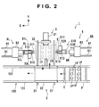
- FIG. 2 is an I-I line arrow view of FIG. 1 .
- Fig. 1 is a front view of the testing device 1
- FIG. 2 corresponds to a plan view excluding a part of the configuration of the testing device 1.
- a specific configuration of a conveying device 100 is omitted.
- the testing device 1 takes in an engine E conveyed in an X-direction by the conveying device 100 which may be a roller conveyer or the like, conducts a test and returns the engine E to the conveying device 100 again after the test.
- the test conducted by the testing device 1 for the engine E is a test conducted in a pseudo driving state without combustion of fuel, and this is a device for conducting a so-called cold test.
- the engine E is a multi-cylinder engine.
- the multi-cylinder engine to which the present invention can be applied is assumed to be a V-type 6-cylinder engine in this embodiment, though the number of cylinders and cylinder arrangement are not particularly limited.
- the engine E has its cylinder row direction in the Y-direction, in which three cylinders each are arranged on one bank.
- One intake port IP is provided in each cylinder independently, and six intake ports IP in total are arranged between the banks.
- an exhaust port EP is a collective exhaust port and provided one port on each bank totaling in two ports. It is needless to say that the present invention can be also applied to a case in which the exhaust port EP is constituted one for each cylinder independently.
- the testing device 1 includes a conveying mechanism 2, a driving unit 3, testing units 4 and 5, a moving mechanism 6, a buffer mechanism 7, and moving mechanisms 8L, 8R, 9L, and 9R.
- Reference character L at the end of reference numeral indicates a configuration corresponding to a test on the left bank when seen in FIG. 1
- reference character R indicates a configuration corresponding to a test on the right bank when seen in FIG. 1 or FIG. 2 .
- These reference characters L and R are omitted in some cases when these configurations do not have to be distinguished. For example, when the moving mechanism 8L and the moving mechanism 8R are not distinguished, they are indicated simply as the moving mechanism 8 in some cases.
- the conveying mechanism 2 is constituted by the conveying device 100 for conveying a pallet P on which the engine E is mounted in the X-direction and a mechanism for taking in the engine E (mounted on the pallet P) conveyed by the conveying device 100 into the testing device 1 or returning the engine E after the test has been completed to the conveying device 100, that is, a movable conveying unit 22.
- the conveying device 100 is constituted by a pair of roller conveyers 101 extended in the X-direction and is provided with a stop device for positioning a work at a predetermined position.
- the movable conveying unit 22 includes an elevation unit 23 for elevating up/down the pallet P, a pair of guide rollers 21 extended in the Y-direction, a slider (not shown) movable along the guide rollers 21, and a driving unit 24 for driving the slider in the Y-direction.
- a known linear driving unit such as a boll screw unit, a linear motor unit and the like, for example, can be cited.
- a free roller can be cited as the guide rollers 21, for example.
- the engine E to be tested is mounted on the pallet P and conveyed on the conveying device 100.
- the pallet P on which the engine E is mounted reaches onto the movable conveying unit 22, the pallet P is positioned at a predetermined position and fixed by the stop device. After that, as the slider is slid by the driving unit 24 to an engagement position with the pallet P, the pallet P is raised by the elevation unit 23. As a result, the pallet P sinks into a lower recessed portion of the slider and is coupled with the pallet P. After that, the slider is slid to the testing device 1 side by the driving unit 24.
- the slider conveys the engine E with the pallet P to a test position (a position of the engine E indicated by a broken line in FIG. 2 ) and stands by during the test. After the test is finished, the slider is slid by the driving unit 24 again to the pallet P side, transfers the pallet P to the conveying device 100 and conveys it. In this way, the continuous testing of the engine E is made possible.
- the driving unit 3 includes a driving source 31 such as an electric motor or the like and a chuck 32 rotated by the driving source 31.
- a driving source 31 such as an electric motor or the like
- a chuck 32 rotated by the driving source 31.
- Testing units 4 and 5 are units for measuring pressure fluctuation of the intake port IP and the exhaust port EP when the engine E is brought into the pseudo driving state.
- the testing unit 4 includes a plurality of pressure inspection units 41L (details will be described later) corresponding to the three intake ports IP on the left bank, one opening/closing mechanism 42L, one support unit 43L, a plurality of pressure inspection units 41R corresponding to the three intake ports IP on the right bank, one opening/closing mechanism 42R, and one support unit 43R as illustrated in FIG. 1 .
- the testing unit 5 includes one pressure inspection unit 51L (details will be described later) corresponding to the one exhaust port EP on the left bank when seen in FIG. 1 , one opening/closing mechanism 52L, one support unit 53L, one pressure inspection unit 51R corresponding to the one exhaust port EP on the right bank, one opening/closing mechanism 52R, and one support unit 53R.
- the moving mechanism 6 moves the testing unit 4 through the buffer mechanism 7.
- the moving mechanism 6 is an elevation mechanism for elevating up/down the testing unit 4 as indicated by an arrow d1 in FIG. 1 and moves the testing unit 4 between an inspection position and a retreated position.
- the inspection position is a position where a pipeline 411 provided in a pressure inspection unit 41 is connected to the intake port IP, while the retreated position is a position where the pipeline 411 is spaced away from the intake port IP.
- the testing unit 4 When the engine E is taken into the testing device 1 from the conveying device 100, the testing unit 4 is moved to the retreated position, and an accommodation space of the engine E is ensured. When a test is to be conducted, the testing unit 4 is moved to the inspection position, and the pipeline 411 is connected to the intake port IP.
- the moving mechanisms 8L and 9L are mechanisms for moving the support unit 53L
- the moving mechanisms 8R and 9R are mechanisms for moving the support unit 53R.
- the pressure inspection unit 51 and the opening/closing mechanism 52 are mounted on the support unit 53.
- the moving mechanisms 8 and 9 move the pressure inspection unit 51 and the opening/closing mechanism 52 between the inspection position and the retreated position by moving the support unit 53.
- FIGs. 1 and 2 exemplify a case in which the pressure inspection unit 51L is at the retreated position and the pressure inspection unit 51R is at the inspection position.
- the inspection position is a position where a tip end of a pipeline 511 provided in the pressure inspection unit 51 is connected to the exhaust port EP
- the retreated position is a position where the pipeline 511 is spaced away from the exhaust port EP.
- the exhaust port EP is opened in an outer wall of the bank, and the outer wall is inclined diagonally downward.
- the moving mechanism 8 advances/retreats the support unit 53 in a direction substantially orthogonal to the outer wall of the bank as indicated by an arrow d3.
- the moving mechanism 9 includes a pair of rails 91 extended in the X-direction and a slider 92 moving by being guided by the rails 91.
- the moving mechanism 8 is mounted on the slider 92 and is moved by the moving mechanism 9 in the X-direction. That is, the support unit 53 is moved in two directions, that is, in the X-direction and a diagonal direction.
- the moving mechanism 8 can be constituted by an air cylinder or an electric cylinder, for example.
- the moving mechanism 9 can be constituted by a driving source such as a motor and the like and a transmission mechanism (a belt transmission mechanism, a ball-screw mechanism, a rack-pinion mechanism and the like, for example) for transmitting a driving force of the driving source, for example.
- the moving mechanism 9 may be constituted by an air cylinder, an electric cylinder or the like.
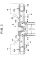
- the pressure inspection units 41 and 51 and prior-art problems will be described by referring to FIG. 3 .
- the same figure illustrates a state at the test by using the pressure inspection units 41 and 51, and the pressure inspection units 41 and 51 are located at the inspection position.
- the exhaust port EP is a collective exhaust port, but for simplification of explanation, it is illustrated as an exhaust port for each cylinder in FIG. 3 .
- the pressure inspection unit 41 is provided one each for the intake port IP. In this embodiment, since six intake ports IP are provided, the pressure inspection units 41 are provided in number of six.
- the pressure inspection unit 41 includes the pipeline 411, a valve 412, and a pressure sensor 413.
- the pipeline 411 is connected to the intake port IP and its internal space communicates with the intake port IP.
- the pipeline 411 is constituted by a metal cylindrical member, for example, and a seal material such as rubber or the like may be provided at its tip end portion 411a so that it is brought into airtight close contact with an opening peripheral edge of the intake port IP.
- a mounting unit 411b on which the pressure sensor 413 is mounted is provided on a peripheral wall of the pipeline 411.
- the mounting unit 411b is formed at a position between the intake port IP and the valve 412.
- the mounting unit 411b is provided by forming a through hole communicating with the internal space of the pipeline 411 in a boss unit where the pressure sensor 413 is fixed by a screw or the like, and a detection unit of the pressure sensor 413 is airtightly inserted into this through hole.
- the pressure sensor 413 is a sensor for measuring an air pressure and detects a pressure of the internal space of the pipeline 411.
- a section opening of the pipeline 411 is opened/closed by opening/closing the valve 412.
- the intake port IP is brought into a communication state with the ambient air, while when it is closed, the intake port IP is brought into a non-communication state with the ambient air.
- the valve 412 is assumed to be a ball valve.
- the valve 412 includes an operation unit 412a and a spherical valve element 412b.
- the operation unit 412a is a valve shaft connected to the valve element 412b, and the valve element 412b is rotated by rotating the operation unit 412a around the shaft so that the valve 412 is opened/closed.
- Rotation ranges of the operation unit 412a and the valve element 412b are assumed to be 90 degrees, and by rotating the operation unit 412a by 90 degrees, the valve element 412b can be switched between an open state and a closed state.
- the rotation of the operation unit 412a is performed by the opening/closing mechanism 42 connected to the operation unit 412a. By driving this opening/closing mechanism 42, the operation unit 412a is rotated, and the valve 412 is opened/closed.
- the opening/closing mechanism 42 is as will be described later.
- the pressure inspection unit 51 is provided one each for each exhaust port EP. In this embodiment, two exhaust ports EP are provided and thus, two pressure inspection units 51 are provided.
- the pressure inspection units 51 have a configuration similar to that of the pressure inspection unit 41.
- the pressure inspection unit 51 includes a pipeline 511, a valve 512, and a pressure sensor 513.
- the pipeline 511 is connected to the exhaust port EP and its internal space communicates with the exhaust port EP.
- the pipeline 511 is constituted by a metal cylindrical member, for example, and its tip end portion 511a can be constituted by a seal material such as rubber or the like so that it is brought into airtight close contact with an opening peripheral edge of the exhaust port EP.
- a mounting unit 511b on which the pressure sensor 513 is mounted is provided on a peripheral wall of the pipeline 511.
- the mounting unit 511b is formed at a position between the exhaust port EP and the valve 512.
- the mounting unit 511b is provided by forming a through hole communicating with the internal space of the pipeline 511 in a boss unit where the pressure sensor 513 is fixed by a screw or the like, and a detection unit of the pressure sensor 513 is airtightly inserted into this through hole.
- the pressure sensor 513 is a sensor for measuring an air pressure and detects a pressure of the internal space of the pipeline 511.
- a section opening of the pipeline 511 is opened/closed by opening/closing the valve 512.
- the exhaust port EP When it is opened, the exhaust port EP is brought into a communication state with the ambient air, while when it is closed, the exhaust port EP is brought into a non-communication state with the ambient air.
- the valve 512 is assumed to be a ball valve.
- the valve 512 includes an operation unit 512a and a spherical valve element 512b.
- the operation unit 512a is a valve shaft connected to the valve element 512b, and the valve element 512b is rotated by rotating the operation unit 512a around the shaft so that the valve 512 is opened/closed.
- Rotation ranges of the operation unit 512a and the valve element 512b are assumed to be 90 degrees, and by rotating the operation unit 512a by 90 degrees, the valve element 512b can be switched between an open state and a closed state.
- the rotation of the operation unit 512a is performed by the opening/closing mechanism 52 connected to the operation unit 512a. By driving this opening/closing mechanism 52, the operation unit 512a is rotated, and the valve 512 is opened/closed.
- the opening/closing mechanism 52 is as will be described later.
- the valve 412 is set in an open state and the valve 512 in a closed state, for example, and the engine E is brought into a pseudo driving state by driving of the driving unit 3.
- Pressure fluctuation of the exhaust port EP is measured by the pressure sensor 513.
- the valve 412 is brought into the closed state and the valve 512 in the open state, for example, and the engine E is brought into the pseudo driving state by driving of the driving unit 3.
- the pressure fluctuation of the intake port IP is measured by the pressure sensor 413.
- valves 412 and 512 need to be brought closer to the intake port IP and the exhaust port EP.
- pressure sensor 413 between the valve 412 and the intake port IP, and an arrangement space for the opening/closing mechanism 42 also needs to be ensured.
- pressure sensor 513 between the valve 512 and the exhaust port EP, and an arrangement space for the opening/closing mechanism 52 also needs to be ensured.
- the ball valve generally has small resistance in opening and high sealing performance in closing and is effective in this type of tests.
- the sealing performance is high, an operation torque required for opening/closing is relatively high, and an actuator which is a driving source becomes large-sized.
- the opening/closing mechanism 42 has a large operation torque and has a tendency that the torque becomes larger as its use frequency increases.
- the opening/closing mechanism 42 is a mechanism which is difficult to be made small-sized. Therefore, in a general configuration in which an actuator for opening/closing the ball valve is provided for each ball valve, a disposition space for the actuator needs to be ensured wide, and there is limitation to reduction of the pipeline lengths L1 and L2.
- the actuator is arranged away from the valve, and the driving force is transmitted through the transmission mechanism.
- automation of opening/closing of the valve can be realized, and the pipeline length can be reduced.
- a configuration on the intake side (the testing unit 4, the moving mechanism 6, and the buffer mechanism 7) will now be described mainly on the configuration of the opening/closing mechanism 42.
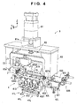
- FIG. 4 is a perspective view of the testing unit 4 and the moving mechanism 6, and
- FIG. 5 is a perspective view of the testing unit 4 and its periphery.
- FIG. 6 is an explanatory view of a lower part of the testing unit 4 and is a partially cutaway view.
- the moving mechanism 6 includes an actuator 61, an elevating body 62, and a support body 63.
- the actuator 61 is an electric cylinder or an air cylinder, for example, and elevates up/down the elevating body 62 by advancing/retreating a rod 61a.
- the testing unit 4 is connected to the elevating body 62.
- the testing unit 4 is suspended from the elevating body 62 through the buffer mechanism 7 and is raised or lowered by elevation of the elevating body 62.
- the support body 63 is fixed to a frame F ( FIG. 1 ) constituting a framework of the testing device 1 and guides elevation of the elevating body 62.
- the buffer mechanism 7 is provided between the support unit 43 of the testing unit 4 and the elevating body 62 of the moving mechanism 6 and connects these relative positions capable of displacement.
- four buffer mechanisms 7 are provided, and two of them are provided between the support unit 43L and the elevating body 62, while the remaining two are provided between the support unit 43R and the elevating body 62. Therefore, the support unit 43R and the support unit 43L are capable of relative displacement in the Z-direction independently of each other with respect to the elevating body 62.
- the elevating body 62 includes four mounting units 62a on which the buffer mechanism 7 is mounted.
- the support unit 43L supports three pressure inspection units 41L and the opening/closing mechanism 42L.
- the support unit 43R supports three pressure inspection units 41R and the opening/closing mechanism 42R.
- the pressure inspection unit 41 and the opening/closing mechanism 42 are also elevated up/down by the elevation of the support unit 43.
- the buffer mechanism 7 includes a rod 71, an elastic member 72, and a stopper 73.
- the rod 71 is a shaft extended in the Z-direction, and the support unit 43 is fixed to its lower end portion.
- An upper end portion of the rod 71 is connected to a part of the elevating body 62.
- a through hole into which the rod 71 is inserted is formed in the mounting unit 62a, and the rod 71 is inserted through this through hole and is extended to above the mounting unit 62a.
- the stopper 73 is fixed to the rod 71 in a part above the mounting unit 62a.
- the stopper 73 regulates a maximum spaced distance of the support unit 43 with respect to the elevating body 62. That is, when the support unit 43 is lowered with respect to the elevating body 62, the rod 71 is also lowered with the support unit 43 but since the stopper 73 is engaged with the mounting unit 62a, lowering of the support unit 43 and the rod 71 is regulated.
- the elastic member 72 is interposed between the mounting unit 62a and the support unit 43 and urges the elevating body 62 and the support unit 43 in a direction in which they are spaced away at all times.
- the elastic member 72 is a coil spring, and the rod 71 is inserted through the elastic member 72.
- the moving mechanism 6 lowers the elevating body 62.
- the pipeline 411 is extended in the Z-direction, and its tip end portion 411a is a lower end portion of the pipeline 411.
- the testing unit 4 is capable of relative displacement in the Z-direction with respect to the elevating body 62.
- an impact when the tip end portion 411a and the opening peripheral edge of the intake port IP are brought into contact with each other is buffered.
- air tightness can be improved by pressing the tip end portion 411a onto the opening peripheral edge of the intake port IP.
- testing unit 4 since it is configured such that the testing unit 4 is connected to the elevating body 62 through the rod 71 and the stopper 73, when the testing unit 4 is to be replaced in association with a model change of the engine E, separation between the elevating body 62 and the testing unit 4 is facilitated, and a replacement work can be performed smoothly.
- elastic member 72 By providing the elastic member 72, in a test operation of the testing unit 4 after replacement, a degree of a force in contact between the pipeline 411 and the opening peripheral edge of the intake port IP is automatically adjusted, and various operation settings required for the test can be facilitated.
- Such a buffer mechanism may be also provided between the testing unit 5 and the moving mechanism 8.
- FIG. 7 is an explanatory view of a lower part of the testing unit 4 and is a partially cutaway view of the opening/closing mechanism 42.
- FIGs. 8A to 8C are operation explanatory views of the opening/closing mechanism 42.
- the opening/closing mechanism 42 includes an actuator 421 and a transmission mechanism 422.
- the actuator 421 outputs a driving force
- the transmission mechanism 422 is connected to the actuator 421 and transmits the driving force to each of the operation units 412a of the plurality of valves 412 (three valves 412 in this embodiment).
- the actuator 421 is provided one each on one opening/closing mechanism 42. That is, the opening/closing mechanisms 42L and 42R include one actuator 421, respectively.
- the actuator 421 is an air cylinder or an electric cylinder in this embodiment and is extended in a direction of a cylinder row (Y-direction) and includes a rod 421a advancing/retreating in the cylinder row direction (Y-direction).
- the actuator 421 is arranged on one end side of the testing unit 4 when seen in the cylinder row direction (Y-direction). In a relation with the pipeline 411, it is arranged away from the pipeline 411 on one end side in a disposition direction of the pipeline 411.
- the disposition space of the actuator 421 is configured not to affect the pipeline lengths L1 and L2 ( FIG. 3 ).
- the transmission mechanism 422 constitutes a link mechanism using the actuator 421 as a driving source in this embodiment.
- the transmission mechanism 422 includes a handle member 4221, a slide member 4222, a link member 4223, and a rail member 4224.
- the handle member 4221 and the link member 4223 are provided for each valve 412. Therefore, the handle members 4221 and the link members 4223 of the opening/closing mechanism 42L are provided in number of three, respectively, and the handle members 4221 and the link members 4223 of the opening/closing mechanism 42R are provided also in number of three, respectively.
- the slide member 4222 and the rail member 4224 are provided one each on one opening/closing mechanism 42. Therefore, the numbers of the slide member 4222 and the rail member 4224 of the opening/closing mechanism 42L are one, respectively, and the numbers of the slide member 4222 and the rail member 4224 of the opening/closing mechanism 42R are one, respectively.
- the handle member 4221 is a plate-shaped member having its one end portion to which the operation unit 412a is connected and extending in a direction orthogonal to the axial direction of the operation unit 412a.
- the operation unit 412a is rotated, and the valve element 412b is rotated.
- a columnar shaped engaging unit 4221a is provided on the other end portion of the handle member 4221.
- the engaging unit 4221a is a roller rotatably fixed to the handle member 4221, for example.
- the slide member 4222 and the rail member 4224 are extended in the cylinder row direction (Y-direction).
- the rail member 4224 is supported by the support unit 43 and guides movement of the slide member 4222 in the cylinder row direction (Y-direction).
- the slide member 4222 is provided on an upper side of the rail member 4224 and is engaged with the rail member 4224 and is slidable in the cylinder row direction (Y-direction).
- a connecting unit 4222a is provided on one end of the slide member 4222, and a tip end of the rod 421a is fixed to this connecting unit 4222a.
- the driving force is transmitted and the slide member 4222 is moved in the cylinder row direction (Y-direction).
- the link member 4223 includes a perpendicular plate-shaped upper part fixed to the slide member 4222, a perpendicular plate-shaped lower part including an engaging unit 4223a, and a horizontal plate-shaped intermediate part connecting the upper part and the lower part.
- the engaging unit 4223a is a groove opened downward in this embodiment, and the lower part of the link member 4223 has a crab claw shape or a spanner shape.
- the engaging unit 4221a of the handle member 4221 is inserted into the engaging unit 4223a and is engaged therewith.
- the engaging unit 4221a of the handle member 4221 may be replaced with a crab claw shape or a spanner shape, while the link member 4223 may be made a roller corresponding to the engaging unit 4221a.
- a coupling structure between the link member 4223 and the slide member 4222 as well as the link member 4223 is not limited to the above-described configuration, and various configurations can be employed.
- FIG. 8A illustrates a state of the opening/closing mechanism 42 when the valve 412 is closed, for example.
- the slide member 4222 is slid to the Y-direction (left direction in FIG. 8A ) and the three link members 4223 coupled to the slide member 4222 are moved in parallel in the Y-direction.
- the engaging unit 4221a of the handle member 4221 is moved and guided along a groove of the engaging unit 4223a and moved to a depth side of the groove and as illustrated in FIG. 8B , the handle member 4221 is rotated around the operation unit 412a.
- the link member 4223 rotates the handle member 4221 around the shaft of the operation unit 412a in conjunction with sliding of the slide member 4222 and rotates the operation unit 412a.
- the valve element 412b is also rotated.
- a state in 8C is brought about.
- the valve 412 is open.
- the three valves 412 are opened/closed at the same time in each bank.
- opening/closing of the valve 412 can be automated.
- the actuator 421 is arranged on one end portion side of the slide member 4222 in the cylinder row direction (Y-direction) and arranged on one end side in the disposition direction of the pipeline 411 away from the pipeline 411 and thus, its disposition space does not affect the pipeline lengths L1 and L2 ( FIG. 3 ). Therefore, when a torque required for opening/closing of the valve 412 increases or higher durability is required in association with an increase in the number of opening/closing times, even if the size of the actuator 421 has to be increased, there is no need to consider an influence on the pipeline lengths L1 and L2, whereby freedom in design is improved.
- valve 412 and the pressure sensor 413 are configured to be adjacent to each other in a direction (horizontal direction, here) orthogonal to a longitudinal direction of the pipeline 411, and a configuration in which the pipeline lengths L1 and L2 ( FIG. 3 ) become shorter is realized.
- the transmission mechanism 422 has the handle member 4221 and the link member 4223 which are a peripheral configuration of the valve 412 constituted by plate-shaped members so as to reduce their dedicated spaces.
- the link member 4223 is formed by bending the upper part, the intermediate part, and the lower part in a crank shape, and a portion adjacent to the valve 412 is only the lower part including the engaging unit 4223a.
- the opening/closing mechanism 52 is different from the opening/closing mechanism 42 in a point that the number of valves to be opened/closed is one, but the other configurations can be the same.
- the opening/closing mechanism 52 can have the handle member 4221 and the link member 4223 one each in the opening/closing mechanism 42, while the others can have the same configuration. If the collective exhaust port assumed in this embodiment is not employed but a plurality of the exhaust ports EP are configured to be provided on one bank, the opening/closing mechanism 52 can have the configuration similar to that of the opening/closing mechanism 42.
Landscapes
- Chemical & Material Sciences (AREA)
- Engineering & Computer Science (AREA)
- Combustion & Propulsion (AREA)
- Physics & Mathematics (AREA)
- General Physics & Mathematics (AREA)
- Testing Of Engines (AREA)
Abstract
Description
- The present invention relates to a testing device and a testing unit of an engine.
- A device for conducting a test without combustion of fuel is proposed as a testing device of an engine. Japanese Patent No.
4315957 - A unit for measuring pressure fluctuation of the intake port and the exhaust port is generally provided with a pipeline connected to the ports, a sensor for detecting a pressure inside the pipeline, and a pipeline valve for opening/closing the pipeline. As a test example, there is a test for checking whether or not responsiveness of the intake/exhaust valve is within a reference value in an overlap zone of the intake/exhaust valve, for example. In this case, a pipeline on an intake side is opened, while the pipeline on the exhaust side is closed, and pressure fluctuation on the intake side is measured. To the contrary, a pipeline on the exhaust side is opened, while the pipeline on the intake side is closed, and pressure fluctuation on the exhaust side is measured.
- From the viewpoint of measurement accuracy of pressure fluctuation, a capacity inside the pipeline from the port to the pipeline valve is preferably small. If the capacity in the pipeline is large,
responsiveness of pressure fluctuation lowers. Thus, a pipeline length from the port to the pipeline valve is preferably small. - On the other hand, a valve with actuator such as an air cylinder is used as the pipeline valve in terms of automation of opening/closing of the valve through automatic control. However, the valve with actuator requires an arrangement space for an actuator and has limitation in reduction of the pipeline length.
- The present invention has an object to realize automation of opening/closing of the valve and to further reduce the pipeline length.
- The present invention in its first aspect provides a testing device as specified in
claims 1 to 6. - The present invention in its second aspect provides a testing unit as specified in
claim 7. - Further features of the present invention will become apparent from the following description of exemplary embodiments (with reference to the attached drawings).
-
-
FIG. 1 is a schematic view of a testing device according to an embodiment of the present invention; -
FIG. 2 is an I-I line arrow view ofFig. 1 ; -
FIG. 3 is an explanatory view of a pressure inspection unit; -
FIG. 4 is a perspective view of a testing unit and a moving mechanism; -
FIG. 5 is a perspective view of the testing unit and its periphery; -
FIG. 6 is an explanatory view of a lower part of the testing unit; -
FIG. 7 is an explanatory view of the lower part of the testing unit; and -
FIGs. 8A to 8C are operation explanatory views of an opening/closing mechanism. - An embodiment of the present invention will be described below. In each figure, an arrow Z indicates a vertical direction, and arrows X and Y indicate horizontal directions orthogonal to each other.
-
Fig. 1 is a schematic view of atesting device 1 according to an embodiment of the present invention, andFIG. 2 is an I-I line arrow view ofFIG. 1 . Assuming thatFig. 1 is a front view of thetesting device 1,FIG. 2 corresponds to a plan view excluding a part of the configuration of thetesting device 1. InFig. 1 , a specific configuration of aconveying device 100 is omitted. - The
testing device 1 takes in an engine E conveyed in an X-direction by theconveying device 100 which may be a roller conveyer or the like, conducts a test and returns the engine E to theconveying device 100 again after the test. The test conducted by thetesting device 1 for the engine E is a test conducted in a pseudo driving state without combustion of fuel, and this is a device for conducting a so-called cold test. - The engine E is a multi-cylinder engine. The multi-cylinder engine to which the present invention can be applied is assumed to be a V-type 6-cylinder engine in this embodiment, though the number of cylinders and cylinder arrangement are not particularly limited. The engine E has its cylinder row direction in the Y-direction, in which three cylinders each are arranged on one bank. One intake port IP is provided in each cylinder independently, and six intake ports IP in total are arranged between the banks. In a case of this embodiment, an exhaust port EP is a collective exhaust port and provided one port on each bank totaling in two ports. It is needless to say that the present invention can be also applied to a case in which the exhaust port EP is constituted one for each cylinder independently.
- The
testing device 1 includes aconveying mechanism 2, a driving unit 3,testing units 4 and 5, amoving mechanism 6, abuffer mechanism 7, andmoving mechanisms FIG. 1 , while reference character R indicates a configuration corresponding to a test on the right bank when seen inFIG. 1 orFIG. 2 . These reference characters L and R are omitted in some cases when these configurations do not have to be distinguished. For example, when themoving mechanism 8L and themoving mechanism 8R are not distinguished, they are indicated simply as the moving mechanism 8 in some cases. - The
conveying mechanism 2 is constituted by theconveying device 100 for conveying a pallet P on which the engine E is mounted in the X-direction and a mechanism for taking in the engine E (mounted on the pallet P) conveyed by theconveying device 100 into thetesting device 1 or returning the engine E after the test has been completed to theconveying device 100, that is, amovable conveying unit 22. Theconveying device 100 is constituted by a pair ofroller conveyers 101 extended in the X-direction and is provided with a stop device for positioning a work at a predetermined position. Themovable conveying unit 22 includes anelevation unit 23 for elevating up/down the pallet P, a pair ofguide rollers 21 extended in the Y-direction, a slider (not shown) movable along theguide rollers 21, and adriving unit 24 for driving the slider in the Y-direction. As thedriving unit 24, a known linear driving unit such as a boll screw unit, a linear motor unit and the like, for example, can be cited. A free roller can be cited as theguide rollers 21, for example. - The engine E to be tested is mounted on the pallet P and conveyed on the
conveying device 100. When the pallet P on which the engine E is mounted reaches onto themovable conveying unit 22, the pallet P is positioned at a predetermined position and fixed by the stop device. After that, as the slider is slid by thedriving unit 24 to an engagement position with the pallet P, the pallet P is raised by theelevation unit 23. As a result, the pallet P sinks into a lower recessed portion of the slider and is coupled with the pallet P. After that, the slider is slid to thetesting device 1 side by thedriving unit 24. - The slider conveys the engine E with the pallet P to a test position (a position of the engine E indicated by a broken line in
FIG. 2 ) and stands by during the test. After the test is finished, the slider is slid by thedriving unit 24 again to the pallet P side, transfers the pallet P to theconveying device 100 and conveys it. In this way, the continuous testing of the engine E is made possible. - The driving unit 3 includes a
driving source 31 such as an electric motor or the like and achuck 32 rotated by thedriving source 31. When the engine E reaches the test position, a crank shaft of the engine E and thedriving source 31 are coupled by thechuck 32. As thedriving source 31 is driven, the crank shaft is rotated, and the engine E can be brought into a pseudo driving state. -
Testing units 4 and 5 are units for measuring pressure fluctuation of the intake port IP and the exhaust port EP when the engine E is brought into the pseudo driving state. - The
testing unit 4 includes a plurality ofpressure inspection units 41L (details will be described later) corresponding to the three intake ports IP on the left bank, one opening/closing mechanism 42L, onesupport unit 43L, a plurality ofpressure inspection units 41R corresponding to the three intake ports IP on the right bank, one opening/closing mechanism 42R, and onesupport unit 43R as illustrated inFIG. 1 . - The testing unit 5 includes one
pressure inspection unit 51L (details will be described later) corresponding to the one exhaust port EP on the left bank when seen inFIG. 1 , one opening/closing mechanism 52L, onesupport unit 53L, onepressure inspection unit 51R corresponding to the one exhaust port EP on the right bank, one opening/closing mechanism 52R, and onesupport unit 53R. - The moving
mechanism 6 moves thetesting unit 4 through thebuffer mechanism 7. In this embodiment, an example of arrangement in which the intake port IP is opened substantially upward on an upper part of the engine E is used as an example. Thus, in this embodiment, the movingmechanism 6 is an elevation mechanism for elevating up/down thetesting unit 4 as indicated by an arrow d1 inFIG. 1 and moves thetesting unit 4 between an inspection position and a retreated position. The inspection position is a position where apipeline 411 provided in a pressure inspection unit 41 is connected to the intake port IP, while the retreated position is a position where thepipeline 411 is spaced away from the intake port IP. When the engine E is taken into thetesting device 1 from the conveyingdevice 100, thetesting unit 4 is moved to the retreated position, and an accommodation space of the engine E is ensured. When a test is to be conducted, thetesting unit 4 is moved to the inspection position, and thepipeline 411 is connected to the intake port IP. - The moving
mechanisms support unit 53L, and the movingmechanisms support unit 53R. Thepressure inspection unit 51 and the opening/closing mechanism 52 are mounted on the support unit 53. The moving mechanisms 8 and 9 move thepressure inspection unit 51 and the opening/closing mechanism 52 between the inspection position and the retreated position by moving the support unit 53.FIGs. 1 and2 exemplify a case in which thepressure inspection unit 51L is at the retreated position and thepressure inspection unit 51R is at the inspection position. The inspection position is a position where a tip end of apipeline 511 provided in thepressure inspection unit 51 is connected to the exhaust port EP, and the retreated position is a position where thepipeline 511 is spaced away from the exhaust port EP. - The exhaust port EP is opened in an outer wall of the bank, and the outer wall is inclined diagonally downward. The moving mechanism 8 advances/retreats the support unit 53 in a direction substantially orthogonal to the outer wall of the bank as indicated by an arrow d3. The moving mechanism 9 includes a pair of
rails 91 extended in the X-direction and aslider 92 moving by being guided by therails 91. The moving mechanism 8 is mounted on theslider 92 and is moved by the moving mechanism 9 in the X-direction. That is, the support unit 53 is moved in two directions, that is, in the X-direction and a diagonal direction. - The moving mechanism 8 can be constituted by an air cylinder or an electric cylinder, for example. The moving mechanism 9 can be constituted by a driving source such as a motor and the like and a transmission mechanism (a belt transmission mechanism, a ball-screw mechanism, a rack-pinion mechanism and the like, for example) for transmitting a driving force of the driving source, for example. The moving mechanism 9 may be constituted by an air cylinder, an electric cylinder or the like.
- The
pressure inspection units 41 and 51 and prior-art problems will be described by referring toFIG. 3 . The same figure illustrates a state at the test by using thepressure inspection units 41 and 51, and thepressure inspection units 41 and 51 are located at the inspection position. In this embodiment, as described above, it is assumed that the exhaust port EP is a collective exhaust port, but for simplification of explanation, it is illustrated as an exhaust port for each cylinder inFIG. 3 . - The pressure inspection unit 41 is provided one each for the intake port IP. In this embodiment, since six intake ports IP are provided, the pressure inspection units 41 are provided in number of six. The pressure inspection unit 41 includes the
pipeline 411, avalve 412, and apressure sensor 413. - The
pipeline 411 is connected to the intake port IP and its internal space communicates with the intake port IP. Thepipeline 411 is constituted by a metal cylindrical member, for example, and a seal material such as rubber or the like may be provided at itstip end portion 411a so that it is brought into airtight close contact with an opening peripheral edge of the intake port IP. - A mounting
unit 411b on which thepressure sensor 413 is mounted is provided on a peripheral wall of thepipeline 411. The mountingunit 411b is formed at a position between the intake port IP and thevalve 412. The mountingunit 411b is provided by forming a through hole communicating with the internal space of thepipeline 411 in a boss unit where thepressure sensor 413 is fixed by a screw or the like, and a detection unit of thepressure sensor 413 is airtightly inserted into this through hole. Thepressure sensor 413 is a sensor for measuring an air pressure and detects a pressure of the internal space of thepipeline 411. - A section opening of the
pipeline 411 is opened/closed by opening/closing thevalve 412. When it is opened, the intake port IP is brought into a communication state with the ambient air, while when it is closed, the intake port IP is brought into a non-communication state with the ambient air. In this embodiment, thevalve 412 is assumed to be a ball valve. Thevalve 412 includes anoperation unit 412a and aspherical valve element 412b. In this embodiment, theoperation unit 412a is a valve shaft connected to thevalve element 412b, and thevalve element 412b is rotated by rotating theoperation unit 412a around the shaft so that thevalve 412 is opened/closed. Rotation ranges of theoperation unit 412a and thevalve element 412b are assumed to be 90 degrees, and by rotating theoperation unit 412a by 90 degrees, thevalve element 412b can be switched between an open state and a closed state. The rotation of theoperation unit 412a is performed by the opening/closing mechanism 42 connected to theoperation unit 412a. By driving this opening/closing mechanism 42, theoperation unit 412a is rotated, and thevalve 412 is opened/closed. The opening/closing mechanism 42 is as will be described later. - The
pressure inspection unit 51 is provided one each for each exhaust port EP. In this embodiment, two exhaust ports EP are provided and thus, twopressure inspection units 51 are provided. Thepressure inspection units 51 have a configuration similar to that of the pressure inspection unit 41. - The
pressure inspection unit 51 includes apipeline 511, avalve 512, and apressure sensor 513. Thepipeline 511 is connected to the exhaust port EP and its internal space communicates with the exhaust port EP. Thepipeline 511 is constituted by a metal cylindrical member, for example, and itstip end portion 511a can be constituted by a seal material such as rubber or the like so that it is brought into airtight close contact with an opening peripheral edge of the exhaust port EP. - A mounting
unit 511b on which thepressure sensor 513 is mounted is provided on a peripheral wall of thepipeline 511. The mountingunit 511b is formed at a position between the exhaust port EP and thevalve 512. The mountingunit 511b is provided by forming a through hole communicating with the internal space of thepipeline 511 in a boss unit where thepressure sensor 513 is fixed by a screw or the like, and a detection unit of thepressure sensor 513 is airtightly inserted into this through hole. Thepressure sensor 513 is a sensor for measuring an air pressure and detects a pressure of the internal space of thepipeline 511. - A section opening of the
pipeline 511 is opened/closed by opening/closing thevalve 512. When it is opened, the exhaust port EP is brought into a communication state with the ambient air, while when it is closed, the exhaust port EP is brought into a non-communication state with the ambient air. In this embodiment, thevalve 512 is assumed to be a ball valve. Thevalve 512 includes anoperation unit 512a and aspherical valve element 512b. In this embodiment, theoperation unit 512a is a valve shaft connected to thevalve element 512b, and thevalve element 512b is rotated by rotating theoperation unit 512a around the shaft so that thevalve 512 is opened/closed. Rotation ranges of theoperation unit 512a and thevalve element 512b are assumed to be 90 degrees, and by rotating theoperation unit 512a by 90 degrees, thevalve element 512b can be switched between an open state and a closed state. The rotation of theoperation unit 512a is performed by the opening/closing mechanism 52 connected to theoperation unit 512a. By driving this opening/closing mechanism 52, theoperation unit 512a is rotated, and thevalve 512 is opened/closed. The opening/closing mechanism 52 is as will be described later. - In a test of the engine E, the
valve 412 is set in an open state and thevalve 512 in a closed state, for example, and the engine E is brought into a pseudo driving state by driving of the driving unit 3. Pressure fluctuation of the exhaust port EP is measured by thepressure sensor 513. Alternatively, thevalve 412 is brought into the closed state and thevalve 512 in the open state, for example, and the engine E is brought into the pseudo driving state by driving of the driving unit 3. The pressure fluctuation of the intake port IP is measured by thepressure sensor 413. - In order to measure the pressure fluctuation of each port more instantaneously, a higher pressure is required, and this depends on the capacity in each port and the capacities of the internal spaces of the
pipelines pipelines valve 412 and a pipeline length L2 from the exhaust port EP to thevalve 512 are made shorter. - In order to make the pipeline lengths L1 and L2 shorter, the
valves pressure sensor 413 between thevalve 412 and the intake port IP, and an arrangement space for the opening/closing mechanism 42 also needs to be ensured. Similarly, there is thepressure sensor 513 between thevalve 512 and the exhaust port EP, and an arrangement space for the opening/closing mechanism 52 also needs to be ensured. - The ball valve generally has small resistance in opening and high sealing performance in closing and is effective in this type of tests. However, since the sealing performance is high, an operation torque required for opening/closing is relatively high, and an actuator which is a driving source becomes large-sized. Moreover, the opening/
closing mechanism 42 has a large operation torque and has a tendency that the torque becomes larger as its use frequency increases. Thus, the opening/closing mechanism 42 is a mechanism which is difficult to be made small-sized. Therefore, in a general configuration in which an actuator for opening/closing the ball valve is provided for each ball valve, a disposition space for the actuator needs to be ensured wide, and there is limitation to reduction of the pipeline lengths L1 and L2. - In this embodiment, the actuator is arranged away from the valve, and the driving force is transmitted through the transmission mechanism. As a result, automation of opening/closing of the valve can be realized, and the pipeline length can be reduced. A configuration on the intake side (the
testing unit 4, the movingmechanism 6, and the buffer mechanism 7) will now be described mainly on the configuration of the opening/closing mechanism 42. - By referring to
FIGs. 1 and4 to 6 , the configurations of thetesting unit 4, the movingmechanism 6, and thebuffer mechanism 7 will be described.FIG. 4 is a perspective view of thetesting unit 4 and the movingmechanism 6, andFIG. 5 is a perspective view of thetesting unit 4 and its periphery.FIG. 6 is an explanatory view of a lower part of thetesting unit 4 and is a partially cutaway view. - The moving
mechanism 6 includes anactuator 61, an elevatingbody 62, and asupport body 63. Theactuator 61 is an electric cylinder or an air cylinder, for example, and elevates up/down the elevatingbody 62 by advancing/retreating arod 61a. To the elevatingbody 62, thetesting unit 4 is connected through thebuffer mechanism 7. Thetesting unit 4 is suspended from the elevatingbody 62 through thebuffer mechanism 7 and is raised or lowered by elevation of the elevatingbody 62. Thesupport body 63 is fixed to a frame F (FIG. 1 ) constituting a framework of thetesting device 1 and guides elevation of the elevatingbody 62. - The
buffer mechanism 7 is provided between the support unit 43 of thetesting unit 4 and the elevatingbody 62 of the movingmechanism 6 and connects these relative positions capable of displacement. In this embodiment, fourbuffer mechanisms 7 are provided, and two of them are provided between thesupport unit 43L and the elevatingbody 62, while the remaining two are provided between thesupport unit 43R and the elevatingbody 62. Therefore, thesupport unit 43R and thesupport unit 43L are capable of relative displacement in the Z-direction independently of each other with respect to the elevatingbody 62. The elevatingbody 62 includes four mountingunits 62a on which thebuffer mechanism 7 is mounted. Thesupport unit 43L supports threepressure inspection units 41L and the opening/closing mechanism 42L. Thesupport unit 43R supports threepressure inspection units 41R and the opening/closing mechanism 42R. The pressure inspection unit 41 and the opening/closing mechanism 42 are also elevated up/down by the elevation of the support unit 43. - The
buffer mechanism 7 includes arod 71, anelastic member 72, and astopper 73. Therod 71 is a shaft extended in the Z-direction, and the support unit 43 is fixed to its lower end portion. An upper end portion of therod 71 is connected to a part of the elevatingbody 62. A through hole into which therod 71 is inserted is formed in the mountingunit 62a, and therod 71 is inserted through this through hole and is extended to above the mountingunit 62a. - The
stopper 73 is fixed to therod 71 in a part above the mountingunit 62a. Thestopper 73 regulates a maximum spaced distance of the support unit 43 with respect to the elevatingbody 62. That is, when the support unit 43 is lowered with respect to the elevatingbody 62, therod 71 is also lowered with the support unit 43 but since thestopper 73 is engaged with the mountingunit 62a, lowering of the support unit 43 and therod 71 is regulated. - The
elastic member 72 is interposed between the mountingunit 62a and the support unit 43 and urges the elevatingbody 62 and the support unit 43 in a direction in which they are spaced away at all times. In this embodiment, theelastic member 72 is a coil spring, and therod 71 is inserted through theelastic member 72. - When the
testing unit 4 is to be moved to the inspection position, the movingmechanism 6 lowers the elevatingbody 62. In relation with arrangement of the intake port IP, as illustrated inFIG. 6 , thepipeline 411 is extended in the Z-direction, and itstip end portion 411a is a lower end portion of thepipeline 411. When thetip end portion 411a of thepipeline 411 is brought into contact with the opening peripheral edge of the intake port IP, thetesting unit 4 is capable of relative displacement in the Z-direction with respect to the elevatingbody 62. Thus, an impact when thetip end portion 411a and the opening peripheral edge of the intake port IP are brought into contact with each other is buffered. By urging of theelastic member 72, air tightness can be improved by pressing thetip end portion 411a onto the opening peripheral edge of the intake port IP. - In addition, since it is configured such that the
testing unit 4 is connected to the elevatingbody 62 through therod 71 and thestopper 73, when thetesting unit 4 is to be replaced in association with a model change of the engine E, separation between the elevatingbody 62 and thetesting unit 4 is facilitated, and a replacement work can be performed smoothly. By providing theelastic member 72, in a test operation of thetesting unit 4 after replacement, a degree of a force in contact between thepipeline 411 and the opening peripheral edge of the intake port IP is automatically adjusted, and various operation settings required for the test can be facilitated. Such a buffer mechanism may be also provided between the testing unit 5 and the moving mechanism 8. - Next, a configuration of the opening/
closing mechanism 42 will be described. In this embodiment, the opening/closing mechanism 42 is provided on each cylinder row (each one side of the banks) of the engine E. The opening/closing mechanism 42L corresponds to the left bank when seen inFIGs. 1 and2 , and the opening/closing mechanism 42R corresponds to the right bank. The opening/closing mechanism 42L and the opening/closing mechanism 42R have the similar configuration. By referring toFIGs. 4 to 8C , the configuration of the opening/closing mechanism 42 will be described below.FIG. 7 is an explanatory view of a lower part of thetesting unit 4 and is a partially cutaway view of the opening/closing mechanism 42.FIGs. 8A to 8C are operation explanatory views of the opening/closing mechanism 42. - The opening/
closing mechanism 42 includes anactuator 421 and atransmission mechanism 422. Theactuator 421 outputs a driving force, and thetransmission mechanism 422 is connected to theactuator 421 and transmits the driving force to each of theoperation units 412a of the plurality of valves 412 (threevalves 412 in this embodiment). - The
actuator 421 is provided one each on one opening/closing mechanism 42. That is, the opening/closing mechanisms actuator 421, respectively. - The
actuator 421 is an air cylinder or an electric cylinder in this embodiment and is extended in a direction of a cylinder row (Y-direction) and includes arod 421a advancing/retreating in the cylinder row direction (Y-direction). Theactuator 421 is arranged on one end side of thetesting unit 4 when seen in the cylinder row direction (Y-direction). In a relation with thepipeline 411, it is arranged away from thepipeline 411 on one end side in a disposition direction of thepipeline 411. In this embodiment as described above, the disposition space of theactuator 421 is configured not to affect the pipeline lengths L1 and L2 (FIG. 3 ). - The
transmission mechanism 422 constitutes a link mechanism using theactuator 421 as a driving source in this embodiment. Thetransmission mechanism 422 includes ahandle member 4221, aslide member 4222, alink member 4223, and arail member 4224. Thehandle member 4221 and thelink member 4223 are provided for eachvalve 412. Therefore, thehandle members 4221 and thelink members 4223 of the opening/closing mechanism 42L are provided in number of three, respectively, and thehandle members 4221 and thelink members 4223 of the opening/closing mechanism 42R are provided also in number of three, respectively. - The
slide member 4222 and therail member 4224 are provided one each on one opening/closing mechanism 42. Therefore, the numbers of theslide member 4222 and therail member 4224 of the opening/closing mechanism 42L are one, respectively, and the numbers of theslide member 4222 and therail member 4224 of the opening/closing mechanism 42R are one, respectively. - As illustrated in
FIGs. 8A to 8C , thehandle member 4221 is a plate-shaped member having its one end portion to which theoperation unit 412a is connected and extending in a direction orthogonal to the axial direction of theoperation unit 412a. By rotating thehandle member 4221 around the axial direction of theoperation unit 412a, theoperation unit 412a is rotated, and thevalve element 412b is rotated. On the other end portion of thehandle member 4221, a columnar shaped engagingunit 4221a is provided. The engagingunit 4221a is a roller rotatably fixed to thehandle member 4221, for example. - The
slide member 4222 and therail member 4224 are extended in the cylinder row direction (Y-direction). Therail member 4224 is supported by the support unit 43 and guides movement of theslide member 4222 in the cylinder row direction (Y-direction). Theslide member 4222 is provided on an upper side of therail member 4224 and is engaged with therail member 4224 and is slidable in the cylinder row direction (Y-direction). - A connecting
unit 4222a is provided on one end of theslide member 4222, and a tip end of therod 421a is fixed to this connectingunit 4222a. When therod 421a is advanced/retreated by driving of theactuator 421, the driving force is transmitted and theslide member 4222 is moved in the cylinder row direction (Y-direction). - Three
link members 4223 are connected to oneslide member 4222. Thelink member 4223 includes a perpendicular plate-shaped upper part fixed to theslide member 4222, a perpendicular plate-shaped lower part including an engagingunit 4223a, and a horizontal plate-shaped intermediate part connecting the upper part and the lower part. The engagingunit 4223a is a groove opened downward in this embodiment, and the lower part of thelink member 4223 has a crab claw shape or a spanner shape. The engagingunit 4221a of thehandle member 4221 is inserted into the engagingunit 4223a and is engaged therewith. As a configuration to the contrary, the engagingunit 4221a of thehandle member 4221 may be replaced with a crab claw shape or a spanner shape, while thelink member 4223 may be made a roller corresponding to the engagingunit 4221a. - A coupling structure between the
link member 4223 and theslide member 4222 as well as thelink member 4223 is not limited to the above-described configuration, and various configurations can be employed. - The opening/closing operation of the
valve 412 by the opening/closing mechanism 42 will be described by referring toFIGs. 8A to 8C. FIG. 8A illustrates a state of the opening/closing mechanism 42 when thevalve 412 is closed, for example. When therod 421a advances by means of driving of theactuator 421, theslide member 4222 is slid to the Y-direction
(left direction inFIG. 8A ) and the threelink members 4223 coupled to theslide member 4222 are moved in parallel in the Y-direction. - At this time, the engaging
unit 4221a of thehandle member 4221 is moved and guided along a groove of the engagingunit 4223a and moved to a depth side of the groove and as illustrated inFIG. 8B , thehandle member 4221 is rotated around theoperation unit 412a. In this way, thelink member 4223 rotates thehandle member 4221 around the shaft of theoperation unit 412a in conjunction with sliding of theslide member 4222 and rotates theoperation unit 412a. As a result, thevalve element 412b is also rotated. - When the
handle member 4221 is rotated in proportion with a slide amount of theslide member 4222, and thehandle member 4221 is rotated by 90 degrees from a state inFIG. 8A , a state in 8C is brought about. At this time, thevalve 412 is open. By retreating therod 421a by driving theactuator 421, the state inFIG. 8C can be returned to the state inFIG. 8A . The threevalves 412 are opened/closed at the same time in each bank. - In this way, in this embodiment, opening/closing of the
valve 412 can be automated. Theactuator 421 is arranged on one end portion side of theslide member 4222 in the cylinder row direction (Y-direction) and arranged on one end side in the disposition direction of thepipeline 411 away from thepipeline 411 and thus, its disposition space does not affect the pipeline lengths L1 and L2 (FIG. 3 ). Therefore, when a torque required for opening/closing of thevalve 412 increases or higher durability is required in association with an increase in the number of opening/closing times, even if the size of theactuator 421 has to be increased, there is no need to consider an influence on the pipeline lengths L1 and L2, whereby freedom in design is improved. - As a result, as illustrated in
FIG. 6 , in this embodiment, thevalve 412 and thepressure sensor 413 are configured to be adjacent to each other in a direction (horizontal direction, here) orthogonal to a longitudinal direction of thepipeline 411, and a configuration in which the pipeline lengths L1 and L2 (FIG. 3 ) become shorter is realized. - The
transmission mechanism 422 has thehandle member 4221 and thelink member 4223 which are a peripheral configuration of thevalve 412 constituted by plate-shaped members so as to reduce their dedicated spaces. Particularly, thelink member 4223 is formed by bending the upper part, the intermediate part, and the lower part in a crank shape, and a portion adjacent to thevalve 412 is only the lower part including the engagingunit 4223a. As a result, a configuration in which thehandle member 4221 and the lower part of thelink member 4223 are arranged in a gap (narrow space) between thevalve 412 and thepressure sensor 413 is realized. - The opening/
closing mechanism 52 is different from the opening/closing mechanism 42 in a point that the number of valves to be opened/closed is one, but the other configurations can be the same. For example, the opening/closing mechanism 52 can have thehandle member 4221 and thelink member 4223 one each in the opening/closing mechanism 42, while the others can have the same configuration. If the collective exhaust port assumed in this embodiment is not employed but a plurality of the exhaust ports EP are configured to be provided on one bank, the opening/closing mechanism 52 can have the configuration similar to that of the opening/closing mechanism 42. - While the present invention has been described with reference to exemplary embodiments, it is to be understood that the invention is not limited to the disclosed exemplary embodiments. The scope of the following claims is to be accorded the broadest interpretation so as to encompass all such modifications and equivalent structures and functions.
Claims (13)
- A testing device (1) configured to test a multi-cylinder engine (E) including a plurality of ports including an intake port (IP) and an exhaust port (EP) in a pseudo driving state, comprising:a plurality of pressure inspection units (41); andat least one opening/closing mechanism (42),wherein each of said plurality of pressure inspection units includes:a pipeline (411) connected to one of the plurality of ports;a sensor (413) for detecting a pressure in the pipeline; anda valve (412) for opening/closing the pipeline, andwherein said opening/closing mechanism includes:one actuator (421); anda transmission mechanism (422) connected to the actuator and transmitting a driving force of the actuator to an operation unit (412a) of each of the plurality of valves to open and close the plurality of valves.
- The testing device according to claim 1, wherein each of the plurality of ports includes a plurality of intake ports (IP);
each pressure inspection unit (41) of the plurality of pressure inspection units is provided on each intake port of the plurality of intake ports; and
said opening/closing mechanism is provided on each cylinder row. - The testing device according to claim 1 or 2, wherein
the operation unit comprises a valve shaft,
the transmission mechanism includes:a plurality of handle members (4221), each handle member being connected to the valve shaft;a slide member (4222) slidable in a cylinder row direction; anda plurality of link members (4223), each link member being coupled to the handle member and the slide member and rotating the handle member around the valve shaft in conjunction with slide of the slide member, andthe actuator is arranged on one end portion side in a cylinder row direction of the slide member and urges the slide member in the cylinder row direction. - The testing device according to any one of claims 1 to 3, further comprising:a support unit (43) configured to support the plurality of pressure inspection units; anda moving mechanism (6) configured to move the support unit between an inspection position where the pipeline is connected to the port and a retreated position where the pipeline is spaced away from the port.
- The testing device according to claim 4, further comprising:a buffer mechanism (7) provided between the support unit and the moving mechanism and connecting these relative positions capable of displacement.
- The testing device according to claim 4 or 5, further comprising:an elevation mechanism configured to elevate up/down the support unit as the moving mechanism (6); anda buffer mechanism (7) provided between the support unit and the elevation mechanism and connecting these relative positions capable of displacement.
- A testing unit (4) configured to test a multi-cylinder engine (E) provided with a plurality of ports including an intake port (IP) and an exhaust port (EP) in a pseudo driving state, comprising:a plurality of pressure inspection units (41); andat least one opening/closing mechanism (42),wherein each of said plurality of pressure inspection units includes:a pipeline (411) connected to one of the plurality of ports; anda valve (412) for opening/closing the pipeline,wherein the pipeline includes a mounting unit (411b) to which a sensor (413) for detecting a pressure in the pipeline is capable of being mounted; andwherein said opening/closing mechanism includes:one actuator (421); anda transmission mechanism (422) connected to the actuator and transmitting a driving force of the actuator to an operation unit (412a) of each of the plurality of valves to open and close the plurality of valves.
- The testing unit according to claim 7, wherein each of the plurality of ports includes a plurality of intake ports (IP);
each pressure inspection unit (41) of the plurality of pressure inspection units is provided on each intake port of the plurality of intake ports; and
said opening/closing mechanism is provided on each cylinder row. - The testing unit according to claim 7 or 8, wherein
the operation unit comprises a valve shaft,
the transmission mechanism includes:a plurality of handle members (4221), each handle member being connected to the valve shaft;a slide member (4222) slidable in a cylinder row direction; anda plurality of link members (4223), each link member being coupled to the handle member and the slide member and rotating the handle member around the valve shaft in conjunction with slide of the slide member, andthe actuator is arranged on one end portion side in a cylinder row direction of the slide member and urges the slide member in the cylinder row direction. - The testing unit according to any one of claims 7 to 9, further comprising:a support unit (43) configured to support the plurality of pressure inspection units; anda moving mechanism (6) configured to move the support unit between an inspection position where the pipeline is connected to the port and a retreated position where the pipeline is spaced away from the port.
- The testing unit according to claim 10, further comprising:a buffer mechanism (7) provided between the support unit and the moving mechanism and connecting these relative positions capable of displacement.
- The testing unit according to claim 10 or 11, further comprising:an elevation mechanism configured to elevate up/down the support unit as the moving mechanism (6); anda buffer mechanism (7) provided between the support unit and the elevation mechanism and connecting these relative positions capable of displacement.
- The testing unit according to any one of claims 7 to 12, further comprising:a sensor (413) for detecting a pressure in the pipeline.
Applications Claiming Priority (1)
| Application Number | Priority Date | Filing Date | Title |
|---|---|---|---|
| JP2014066733A JP6276085B2 (en) | 2014-03-27 | 2014-03-27 | Test equipment and test unit |
Publications (2)
| Publication Number | Publication Date |
|---|---|
| EP2924413A1 true EP2924413A1 (en) | 2015-09-30 |
| EP2924413B1 EP2924413B1 (en) | 2017-08-09 |
Family
ID=52823428
Family Applications (1)
| Application Number | Title | Priority Date | Filing Date |
|---|---|---|---|
| EP15000906.6A Not-in-force EP2924413B1 (en) | 2014-03-27 | 2015-03-27 | Engine component testing device |
Country Status (4)
| Country | Link |
|---|---|
| US (1) | US9804056B2 (en) |
| EP (1) | EP2924413B1 (en) |
| JP (1) | JP6276085B2 (en) |
| CN (1) | CN104949837A (en) |
Families Citing this family (6)
| Publication number | Priority date | Publication date | Assignee | Title |
|---|---|---|---|---|
| CN105223024A (en) * | 2015-11-09 | 2016-01-06 | 攀钢集团矿业有限公司 | For the testing table of engine thermal break-in |
| KR101819896B1 (en) * | 2016-12-01 | 2018-02-28 | (주)모토닉 | Apparatus and Method for testing engine CVV duration mechanism |
| JP6480080B1 (en) * | 2017-03-31 | 2019-03-06 | 平田機工株式会社 | Engine test equipment |
| CN111175051A (en) * | 2018-11-13 | 2020-05-19 | 上海华依科技集团股份有限公司 | Compression pressure test system and test method for engine cold test |
| CN111337271A (en) * | 2020-03-31 | 2020-06-26 | 昆山顺扬工业成套设备有限公司 | Oval car strength testing device |
| US11635349B1 (en) * | 2021-11-30 | 2023-04-25 | Honda Motor Co., Ltd. | Valve testing apparatus |
Citations (2)
| Publication number | Priority date | Publication date | Assignee | Title |
|---|---|---|---|---|
| US5417109A (en) * | 1993-09-30 | 1995-05-23 | Lucas Automation & Control Engineering, Inc. | Methods and apparatus for testing engines |
| EP1693661A1 (en) * | 2003-12-12 | 2006-08-23 | Hirata Corporation | Test equipment of engine motoring |
Family Cites Families (10)
| Publication number | Priority date | Publication date | Assignee | Title |
|---|---|---|---|---|
| JPS5759342U (en) * | 1980-09-25 | 1982-04-08 | ||
| JPH0721638Y2 (en) | 1992-03-03 | 1995-05-17 | 有限会社トシヒロ産業 | Interlocking switching valve |
| JP2724942B2 (en) * | 1992-07-06 | 1998-03-09 | 本田技研工業株式会社 | Engine valve timing measurement device |
| US5492006A (en) * | 1993-11-29 | 1996-02-20 | Bauer Associates, Inc. | Method of testing internal combustion engine |
| JP3624589B2 (en) * | 1996-11-21 | 2005-03-02 | トヨタ自動車株式会社 | Engine inspection method |
| CN1296689C (en) | 1996-07-19 | 2007-01-24 | 丰田自动车株式会社 | Method of testing assembled internal combustion engine |
| JP3122391B2 (en) * | 1997-07-01 | 2001-01-09 | 三菱重工業株式会社 | Multi-valve interlocking switching device |
| JP3906833B2 (en) | 2003-10-14 | 2007-04-18 | マツダ株式会社 | Engine exhaust pressure detector |
| JP4827902B2 (en) | 2008-09-08 | 2011-11-30 | 平田機工株式会社 | Method and apparatus for measuring and adjusting valve clearance |
| CN102022142B (en) | 2009-09-23 | 2013-09-11 | 上海电气电站设备有限公司 | Built-in steam extraction controlling and regulating valve set for steam turbine |
-
2014
- 2014-03-27 JP JP2014066733A patent/JP6276085B2/en not_active Expired - Fee Related
-
2015
- 2015-03-26 US US14/670,052 patent/US9804056B2/en not_active Expired - Fee Related
- 2015-03-27 EP EP15000906.6A patent/EP2924413B1/en not_active Not-in-force
- 2015-03-27 CN CN201510140473.6A patent/CN104949837A/en active Pending
Patent Citations (3)
| Publication number | Priority date | Publication date | Assignee | Title |
|---|---|---|---|---|
| US5417109A (en) * | 1993-09-30 | 1995-05-23 | Lucas Automation & Control Engineering, Inc. | Methods and apparatus for testing engines |
| EP1693661A1 (en) * | 2003-12-12 | 2006-08-23 | Hirata Corporation | Test equipment of engine motoring |
| JP4315957B2 (en) | 2003-12-12 | 2009-08-19 | 平田機工株式会社 | Engine motoring test equipment |
Also Published As
| Publication number | Publication date |
|---|---|
| US9804056B2 (en) | 2017-10-31 |
| US20150276551A1 (en) | 2015-10-01 |
| EP2924413B1 (en) | 2017-08-09 |
| JP6276085B2 (en) | 2018-02-07 |
| CN104949837A (en) | 2015-09-30 |
| JP2015190797A (en) | 2015-11-02 |
Similar Documents
| Publication | Publication Date | Title |
|---|---|---|
| EP2924413B1 (en) | Engine component testing device | |
| US7849734B2 (en) | Test equipment of engine motoring | |
| CN104030028A (en) | Conveyor for tire testing machine | |
| US8467989B2 (en) | Clearance measuring method and measuring unit | |
| KR20100047926A (en) | Micro robot mechanism for nondestructive aging evaluation of cable | |
| WO2010026797A1 (en) | Method and device for measuring and adjusting valve clearance | |
| TWM469491U (en) | Inspection device with dual-axis positioning mechanism | |
| CN108955468A (en) | A kind of three reference circle fluid torque-converter screw hole automatic detection devices | |
| WO2017022968A1 (en) | Bidirectional gate valve | |
| CN204330016U (en) | Integration commutator detecting device | |
| CN210014738U (en) | Go-no go gauge detection mechanism for product inner diameter detection | |
| KR102088788B1 (en) | Engine test device | |
| KR102618032B1 (en) | Rotor inspection equipment | |
| CN203751677U (en) | Valve assembly line | |
| TWM448687U (en) | Testing apparatus with turn-over device | |
| KR101129056B1 (en) | Apparatus for inspection of the internal diameter of small sized compression spring | |
| CN209399875U (en) | A kind of three reference circle fluid torque-converter screw hole automatic detection devices | |
| CN118491881A (en) | A bearing appearance inspection machine | |
| KR101238392B1 (en) | Apparatus and method for measuring thickness of taper leaf spring for vehicle | |
| CN116429050A (en) | Camshaft axiality detecting system | |
| CN209945217U (en) | Inner diameter passing detection device | |
| CN221959467U (en) | Adaptive adjustment device of ultrasonic thickness gauge probe for water-cooled wall inspection | |
| CN206192314U (en) | Piston pin size detection device | |
| CN119870975B (en) | Pressing plate and guide flat key assembling and bore closing combined machining equipment | |
| TW202026548A (en) | Linear transimission device |
Legal Events
| Date | Code | Title | Description |
|---|---|---|---|
| PUAI | Public reference made under article 153(3) epc to a published international application that has entered the european phase |
Free format text: ORIGINAL CODE: 0009012 |
|
| AK | Designated contracting states |
Kind code of ref document: A1 Designated state(s): AL AT BE BG CH CY CZ DE DK EE ES FI FR GB GR HR HU IE IS IT LI LT LU LV MC MK MT NL NO PL PT RO RS SE SI SK SM TR |
|
| AX | Request for extension of the european patent |
Extension state: BA ME |
|
| 17P | Request for examination filed |
Effective date: 20160329 |
|
| RBV | Designated contracting states (corrected) |
Designated state(s): AL AT BE BG CH CY CZ DE DK EE ES FI FR GB GR HR HU IE IS IT LI LT LU LV MC MK MT NL NO PL PT RO RS SE SI SK SM TR |
|
| 17Q | First examination report despatched |
Effective date: 20161114 |
|
| REG | Reference to a national code |
Ref country code: DE Ref legal event code: R079 Ref document number: 602015003917 Country of ref document: DE Free format text: PREVIOUS MAIN CLASS: G01M0015080000 Ipc: G01M0015050000 |
|
| GRAP | Despatch of communication of intention to grant a patent |
Free format text: ORIGINAL CODE: EPIDOSNIGR1 |
|
| RIC1 | Information provided on ipc code assigned before grant |
Ipc: G01M 15/08 20060101ALI20170208BHEP Ipc: G01M 15/05 20060101AFI20170208BHEP Ipc: G01M 15/10 20060101ALI20170208BHEP Ipc: G01M 15/09 20060101ALI20170208BHEP |
|
| INTG | Intention to grant announced |
Effective date: 20170223 |
|
| GRAS | Grant fee paid |
Free format text: ORIGINAL CODE: EPIDOSNIGR3 |
|
| GRAA | (expected) grant |
Free format text: ORIGINAL CODE: 0009210 |
|
| RAP1 | Party data changed (applicant data changed or rights of an application transferred) |
Owner name: HIRATA CORPORATION |
|
| RIN1 | Information on inventor provided before grant (corrected) |
Inventor name: UCHIDA, TSUYOSHI Inventor name: SUEOKA, HISAYUKI |
|
| AK | Designated contracting states |
Kind code of ref document: B1 Designated state(s): AL AT BE BG CH CY CZ DE DK EE ES FI FR GB GR HR HU IE IS IT LI LT LU LV MC MK MT NL NO PL PT RO RS SE SI SK SM TR |
|
| REG | Reference to a national code |
Ref country code: GB Ref legal event code: FG4D |
|
| REG | Reference to a national code |
Ref country code: CH Ref legal event code: EP Ref country code: AT Ref legal event code: REF Ref document number: 917367 Country of ref document: AT Kind code of ref document: T Effective date: 20170815 |
|
| REG | Reference to a national code |
Ref country code: IE Ref legal event code: FG4D |
|
| REG | Reference to a national code |
Ref country code: DE Ref legal event code: R096 Ref document number: 602015003917 Country of ref document: DE |
|
| REG | Reference to a national code |
Ref country code: NL Ref legal event code: MP Effective date: 20170809 |
|
| REG | Reference to a national code |
Ref country code: LT Ref legal event code: MG4D |
|
| REG | Reference to a national code |
Ref country code: AT Ref legal event code: MK05 Ref document number: 917367 Country of ref document: AT Kind code of ref document: T Effective date: 20170809 |
|
| PG25 | Lapsed in a contracting state [announced via postgrant information from national office to epo] |
Ref country code: FI Free format text: LAPSE BECAUSE OF FAILURE TO SUBMIT A TRANSLATION OF THE DESCRIPTION OR TO PAY THE FEE WITHIN THE PRESCRIBED TIME-LIMIT Effective date: 20170809 Ref country code: AT Free format text: LAPSE BECAUSE OF FAILURE TO SUBMIT A TRANSLATION OF THE DESCRIPTION OR TO PAY THE FEE WITHIN THE PRESCRIBED TIME-LIMIT Effective date: 20170809 Ref country code: SE Free format text: LAPSE BECAUSE OF FAILURE TO SUBMIT A TRANSLATION OF THE DESCRIPTION OR TO PAY THE FEE WITHIN THE PRESCRIBED TIME-LIMIT Effective date: 20170809 Ref country code: NO Free format text: LAPSE BECAUSE OF FAILURE TO SUBMIT A TRANSLATION OF THE DESCRIPTION OR TO PAY THE FEE WITHIN THE PRESCRIBED TIME-LIMIT Effective date: 20171109 Ref country code: NL Free format text: LAPSE BECAUSE OF FAILURE TO SUBMIT A TRANSLATION OF THE DESCRIPTION OR TO PAY THE FEE WITHIN THE PRESCRIBED TIME-LIMIT Effective date: 20170809 Ref country code: LT Free format text: LAPSE BECAUSE OF FAILURE TO SUBMIT A TRANSLATION OF THE DESCRIPTION OR TO PAY THE FEE WITHIN THE PRESCRIBED TIME-LIMIT Effective date: 20170809 Ref country code: HR Free format text: LAPSE BECAUSE OF FAILURE TO SUBMIT A TRANSLATION OF THE DESCRIPTION OR TO PAY THE FEE WITHIN THE PRESCRIBED TIME-LIMIT Effective date: 20170809 |
|
| PG25 | Lapsed in a contracting state [announced via postgrant information from national office to epo] |
Ref country code: RS Free format text: LAPSE BECAUSE OF FAILURE TO SUBMIT A TRANSLATION OF THE DESCRIPTION OR TO PAY THE FEE WITHIN THE PRESCRIBED TIME-LIMIT Effective date: 20170809 Ref country code: BG Free format text: LAPSE BECAUSE OF FAILURE TO SUBMIT A TRANSLATION OF THE DESCRIPTION OR TO PAY THE FEE WITHIN THE PRESCRIBED TIME-LIMIT Effective date: 20171109 Ref country code: ES Free format text: LAPSE BECAUSE OF FAILURE TO SUBMIT A TRANSLATION OF THE DESCRIPTION OR TO PAY THE FEE WITHIN THE PRESCRIBED TIME-LIMIT Effective date: 20170809 Ref country code: IS Free format text: LAPSE BECAUSE OF FAILURE TO SUBMIT A TRANSLATION OF THE DESCRIPTION OR TO PAY THE FEE WITHIN THE PRESCRIBED TIME-LIMIT Effective date: 20171209 Ref country code: PL Free format text: LAPSE BECAUSE OF FAILURE TO SUBMIT A TRANSLATION OF THE DESCRIPTION OR TO PAY THE FEE WITHIN THE PRESCRIBED TIME-LIMIT Effective date: 20170809 Ref country code: LV Free format text: LAPSE BECAUSE OF FAILURE TO SUBMIT A TRANSLATION OF THE DESCRIPTION OR TO PAY THE FEE WITHIN THE PRESCRIBED TIME-LIMIT Effective date: 20170809 Ref country code: GR Free format text: LAPSE BECAUSE OF FAILURE TO SUBMIT A TRANSLATION OF THE DESCRIPTION OR TO PAY THE FEE WITHIN THE PRESCRIBED TIME-LIMIT Effective date: 20171110 |
|
| PG25 | Lapsed in a contracting state [announced via postgrant information from national office to epo] |
Ref country code: RO Free format text: LAPSE BECAUSE OF FAILURE TO SUBMIT A TRANSLATION OF THE DESCRIPTION OR TO PAY THE FEE WITHIN THE PRESCRIBED TIME-LIMIT Effective date: 20170809 Ref country code: DK Free format text: LAPSE BECAUSE OF FAILURE TO SUBMIT A TRANSLATION OF THE DESCRIPTION OR TO PAY THE FEE WITHIN THE PRESCRIBED TIME-LIMIT Effective date: 20170809 Ref country code: CZ Free format text: LAPSE BECAUSE OF FAILURE TO SUBMIT A TRANSLATION OF THE DESCRIPTION OR TO PAY THE FEE WITHIN THE PRESCRIBED TIME-LIMIT Effective date: 20170809 |
|
| REG | Reference to a national code |
Ref country code: DE Ref legal event code: R097 Ref document number: 602015003917 Country of ref document: DE |
|
| PG25 | Lapsed in a contracting state [announced via postgrant information from national office to epo] |
Ref country code: IT Free format text: LAPSE BECAUSE OF FAILURE TO SUBMIT A TRANSLATION OF THE DESCRIPTION OR TO PAY THE FEE WITHIN THE PRESCRIBED TIME-LIMIT Effective date: 20170809 Ref country code: SK Free format text: LAPSE BECAUSE OF FAILURE TO SUBMIT A TRANSLATION OF THE DESCRIPTION OR TO PAY THE FEE WITHIN THE PRESCRIBED TIME-LIMIT Effective date: 20170809 Ref country code: EE Free format text: LAPSE BECAUSE OF FAILURE TO SUBMIT A TRANSLATION OF THE DESCRIPTION OR TO PAY THE FEE WITHIN THE PRESCRIBED TIME-LIMIT Effective date: 20170809 Ref country code: SM Free format text: LAPSE BECAUSE OF FAILURE TO SUBMIT A TRANSLATION OF THE DESCRIPTION OR TO PAY THE FEE WITHIN THE PRESCRIBED TIME-LIMIT Effective date: 20170809 |
|
| PLBE | No opposition filed within time limit |
Free format text: ORIGINAL CODE: 0009261 |
|
| STAA | Information on the status of an ep patent application or granted ep patent |
Free format text: STATUS: NO OPPOSITION FILED WITHIN TIME LIMIT |
|
| 26N | No opposition filed |
Effective date: 20180511 |
|
| PG25 | Lapsed in a contracting state [announced via postgrant information from national office to epo] |
Ref country code: SI Free format text: LAPSE BECAUSE OF FAILURE TO SUBMIT A TRANSLATION OF THE DESCRIPTION OR TO PAY THE FEE WITHIN THE PRESCRIBED TIME-LIMIT Effective date: 20170809 |
|
| REG | Reference to a national code |
Ref country code: CH Ref legal event code: PL |
|
| PG25 | Lapsed in a contracting state [announced via postgrant information from national office to epo] |
Ref country code: MC Free format text: LAPSE BECAUSE OF FAILURE TO SUBMIT A TRANSLATION OF THE DESCRIPTION OR TO PAY THE FEE WITHIN THE PRESCRIBED TIME-LIMIT Effective date: 20170809 |
|
| REG | Reference to a national code |
Ref country code: BE Ref legal event code: MM Effective date: 20180331 |
|
| REG | Reference to a national code |
Ref country code: IE Ref legal event code: MM4A |
|
| PG25 | Lapsed in a contracting state [announced via postgrant information from national office to epo] |
Ref country code: LU Free format text: LAPSE BECAUSE OF NON-PAYMENT OF DUE FEES Effective date: 20180327 |
|
| PG25 | Lapsed in a contracting state [announced via postgrant information from national office to epo] |
Ref country code: IE Free format text: LAPSE BECAUSE OF NON-PAYMENT OF DUE FEES Effective date: 20180327 |
|
| PG25 | Lapsed in a contracting state [announced via postgrant information from national office to epo] |
Ref country code: BE Free format text: LAPSE BECAUSE OF NON-PAYMENT OF DUE FEES Effective date: 20180331 Ref country code: CH Free format text: LAPSE BECAUSE OF NON-PAYMENT OF DUE FEES Effective date: 20180331 Ref country code: LI Free format text: LAPSE BECAUSE OF NON-PAYMENT OF DUE FEES Effective date: 20180331 |
|
| PG25 | Lapsed in a contracting state [announced via postgrant information from national office to epo] |
Ref country code: FR Free format text: LAPSE BECAUSE OF NON-PAYMENT OF DUE FEES Effective date: 20180331 |
|
| GBPC | Gb: european patent ceased through non-payment of renewal fee |
Effective date: 20190327 |
|
| PG25 | Lapsed in a contracting state [announced via postgrant information from national office to epo] |
Ref country code: GB Free format text: LAPSE BECAUSE OF NON-PAYMENT OF DUE FEES Effective date: 20190327 Ref country code: MT Free format text: LAPSE BECAUSE OF NON-PAYMENT OF DUE FEES Effective date: 20180327 |
|
| PG25 | Lapsed in a contracting state [announced via postgrant information from national office to epo] |
Ref country code: TR Free format text: LAPSE BECAUSE OF FAILURE TO SUBMIT A TRANSLATION OF THE DESCRIPTION OR TO PAY THE FEE WITHIN THE PRESCRIBED TIME-LIMIT Effective date: 20170809 |
|
| PG25 | Lapsed in a contracting state [announced via postgrant information from national office to epo] |
Ref country code: PT Free format text: LAPSE BECAUSE OF FAILURE TO SUBMIT A TRANSLATION OF THE DESCRIPTION OR TO PAY THE FEE WITHIN THE PRESCRIBED TIME-LIMIT Effective date: 20170809 |
|
| PG25 | Lapsed in a contracting state [announced via postgrant information from national office to epo] |
Ref country code: HU Free format text: LAPSE BECAUSE OF FAILURE TO SUBMIT A TRANSLATION OF THE DESCRIPTION OR TO PAY THE FEE WITHIN THE PRESCRIBED TIME-LIMIT; INVALID AB INITIO Effective date: 20150327 Ref country code: CY Free format text: LAPSE BECAUSE OF FAILURE TO SUBMIT A TRANSLATION OF THE DESCRIPTION OR TO PAY THE FEE WITHIN THE PRESCRIBED TIME-LIMIT Effective date: 20170809 Ref country code: MK Free format text: LAPSE BECAUSE OF NON-PAYMENT OF DUE FEES Effective date: 20170809 |
|
| PG25 | Lapsed in a contracting state [announced via postgrant information from national office to epo] |
Ref country code: AL Free format text: LAPSE BECAUSE OF FAILURE TO SUBMIT A TRANSLATION OF THE DESCRIPTION OR TO PAY THE FEE WITHIN THE PRESCRIBED TIME-LIMIT Effective date: 20170809 |
|
| PGFP | Annual fee paid to national office [announced via postgrant information from national office to epo] |
Ref country code: DE Payment date: 20210316 Year of fee payment: 7 |
|
| REG | Reference to a national code |
Ref country code: DE Ref legal event code: R119 Ref document number: 602015003917 Country of ref document: DE |
|
| PG25 | Lapsed in a contracting state [announced via postgrant information from national office to epo] |
Ref country code: DE Free format text: LAPSE BECAUSE OF NON-PAYMENT OF DUE FEES Effective date: 20221001 |