JP6276085B2 - Test equipment and test unit - Google Patents
Test equipment and test unit Download PDFInfo
- Publication number
- JP6276085B2 JP6276085B2 JP2014066733A JP2014066733A JP6276085B2 JP 6276085 B2 JP6276085 B2 JP 6276085B2 JP 2014066733 A JP2014066733 A JP 2014066733A JP 2014066733 A JP2014066733 A JP 2014066733A JP 6276085 B2 JP6276085 B2 JP 6276085B2
- Authority
- JP
- Japan
- Prior art keywords
- pipe
- opening
- test
- actuator
- unit
- Prior art date
- Legal status (The legal status is an assumption and is not a legal conclusion. Google has not performed a legal analysis and makes no representation as to the accuracy of the status listed.)
- Expired - Fee Related
Links
Images


Classifications
-
- G—PHYSICS
- G01—MEASURING; TESTING
- G01M—TESTING STATIC OR DYNAMIC BALANCE OF MACHINES OR STRUCTURES; TESTING OF STRUCTURES OR APPARATUS, NOT OTHERWISE PROVIDED FOR
- G01M15/00—Testing of engines
- G01M15/04—Testing internal-combustion engines
- G01M15/09—Testing internal-combustion engines by monitoring pressure in fluid ducts, e.g. in lubrication or cooling parts
-
- G—PHYSICS
- G01—MEASURING; TESTING
- G01M—TESTING STATIC OR DYNAMIC BALANCE OF MACHINES OR STRUCTURES; TESTING OF STRUCTURES OR APPARATUS, NOT OTHERWISE PROVIDED FOR
- G01M15/00—Testing of engines
- G01M15/04—Testing internal-combustion engines
- G01M15/05—Testing internal-combustion engines by combined monitoring of two or more different engine parameters
-
- G—PHYSICS
- G01—MEASURING; TESTING
- G01M—TESTING STATIC OR DYNAMIC BALANCE OF MACHINES OR STRUCTURES; TESTING OF STRUCTURES OR APPARATUS, NOT OTHERWISE PROVIDED FOR
- G01M15/00—Testing of engines
- G01M15/04—Testing internal-combustion engines
- G01M15/08—Testing internal-combustion engines by monitoring pressure in cylinders
-
- G—PHYSICS
- G01—MEASURING; TESTING
- G01M—TESTING STATIC OR DYNAMIC BALANCE OF MACHINES OR STRUCTURES; TESTING OF STRUCTURES OR APPARATUS, NOT OTHERWISE PROVIDED FOR
- G01M15/00—Testing of engines
- G01M15/04—Testing internal-combustion engines
- G01M15/10—Testing internal-combustion engines by monitoring exhaust gases or combustion flame
- G01M15/102—Testing internal-combustion engines by monitoring exhaust gases or combustion flame by monitoring exhaust gases
- G01M15/106—Testing internal-combustion engines by monitoring exhaust gases or combustion flame by monitoring exhaust gases using pressure sensors
Description
本発明はエンジンの試験装置及び試験ユニットに関する。 The present invention relates to an engine test apparatus and a test unit.
エンジンの試験装置として、燃料の燃焼を伴わずに試験を行う装置が提案されている。例えば、特許文献1にはクランク軸を電動モータで回転させ、吸気ポートや排気ポートの圧力変動を計測する装置が開示されている。
As an engine test apparatus, an apparatus that performs a test without burning fuel has been proposed. For example,
吸気ポートや排気ポートの圧力変動を計測するユニットは、一般に、ポートに接続される配管と、配管内の圧力を検出するセンサと、配管を開閉する配管用バルブとを備える。試験例として、例えば、吸排気バルブのオーバラップゾーンにおいて、吸排気バルブの応答性が基準値内に収まっているか否かを確認する試験がある。この場合、吸気側の配管を開放し、排気側の配管を閉鎖して吸気側の圧力変動を計測し、逆に、排気側の配管を開放し、吸気側の配管を閉鎖して排気側の圧力変動を計測する。 A unit that measures pressure fluctuations in an intake port and an exhaust port generally includes a pipe connected to the port, a sensor that detects a pressure in the pipe, and a pipe valve that opens and closes the pipe. As a test example, for example, there is a test for confirming whether the response of the intake / exhaust valve is within a reference value in the overlap zone of the intake / exhaust valve. In this case, open the intake side pipe, close the exhaust side pipe and measure the intake side pressure fluctuation, and conversely open the exhaust side pipe, close the intake side pipe and close the exhaust side pipe. Measure pressure fluctuations.
圧力変動の計測精度の点で、ポートから配管用バルブに至る配管内の容積は小さい方が好ましい。配管内の容積が大きいと圧力変動の応答性が低下する。そこで、ポートから配管用バルブに至る配管長はできるだけ短い方が好ましい。 From the viewpoint of pressure fluctuation measurement accuracy, it is preferable that the volume in the pipe from the port to the pipe valve is small. If the volume in the pipe is large, the response to pressure fluctuations will decrease. Therefore, it is preferable that the piping length from the port to the piping valve is as short as possible.
一方、配管用バルブとしては、自動制御によるバルブの開閉の自動化の点で、エアシリンダ等のアクチュエータ付きのバルブが用いられる。しかし、アクチュエータ付きのバルブは、アクチュエータの配置スペースが必要とされ、配管長を短くするのに限界がある。 On the other hand, as a valve for piping, a valve with an actuator such as an air cylinder is used in terms of automating the opening and closing of the valve by automatic control. However, a valve with an actuator requires a space for arranging the actuator, and there is a limit to shortening the pipe length.
本発明の目的は、バルブの開閉の自動化を可能とし、かつ、配管長をより短くすることにある。 An object of the present invention is to enable automatic opening / closing of a valve and to shorten a pipe length.
本発明によれば、吸気ポート及び排気ポートを含む複数のポートを備える多気筒エンジンを、擬似的な駆動状態で試験するための試験ユニットであって、複数の圧力検査ユニットと、少なくとも一つの開閉機構と、を備え、前記複数の圧力検査ユニットは、それぞれ、前記複数のポートのうちの一つに接続される配管と、前記配管を開閉するバルブと、を備え、前記配管は、前記吸気ポート又は前記排気ポートと前記バルブとの間の位置に設けられ、前記配管内の圧力を検出するセンサが取り付けられる取付部を備え、前記開閉機構は、一つのアクチュエータと、前記アクチュエータに接続され、前記アクチュエータの駆動力を複数の前記バルブの各操作部に伝達して、前記複数のバルブを開閉する伝達機構と、を備え、前記伝達機構は、前記アクチュエータの駆動により、気筒列方向にスライド自在なスライド部材と、複数の前記バルブの各操作部に一方端部がそれぞれ接続されるハンドル部材と、先端側が該ハンドル部材の他方端部にそれぞれ係合され、根元側が前記スライド部材にそれぞれ固定されるリンク部材と、を備える、ことを特徴とする試験ユニットが提供される。
また、本発明によれば、吸気ポート及び排気ポートを含む複数のポートを備えた多気筒エンジンを、擬似的な駆動状態で試験する試験装置であって、複数の圧力検査ユニットと、少なくとも一つの開閉機構と、を備え、前記複数の圧力検査ユニットは、それぞれ、前記複数のポートのうちの一つに接続される配管と、前記配管内の圧力を検出するセンサと、前記配管を開閉するバルブと、を備え、前記試験装置は、前記複数の圧力検査ユニットを支持する支持ユニットと、前記配管が前記ポートに接続される検査位置と、前記配管が前記ポートから離間した退避位置との間で、前記支持ユニットを移動させる移動機構と、前記支持ユニットと前記移動機構との間に設けられ、これらの相対位置を変位可能に接続する緩衝機構と、を更に備え、前記開閉機構は、一つのアクチュエータと、前記アクチュエータに接続され、前記アクチュエータの駆動力を複数の前記バルブの各操作部に伝達して、前記複数のバルブを開閉する伝達機構と、を備える、ことを特徴とする試験装置が提供される。
また、本発明によれば、吸気ポート及び排気ポートを含む複数のポートを備えた多気筒エンジンを、擬似的な駆動状態で試験する試験装置であって、複数の圧力検査ユニットと、少なくとも一つの開閉機構と、を備え、前記複数の圧力検査ユニットは、それぞれ、前記複数のポートのうちの一つに接続される配管と、前記配管内の圧力を検出するセンサと、前記配管を開閉するバルブと、を備え、前記試験装置は、前記複数の圧力検査ユニットを支持する支持ユニットと、前記配管が前記ポートに接続される検査位置と、前記配管が前記ポートから離間した退避位置との間で、前記支持ユニットを昇降させる昇降機構と、前記支持ユニットと前記昇降機構との間に設けられ、これらの相対位置を変位可能に接続する緩衝機構と、を更に備え、前記開閉機構は、一つのアクチュエータと、前記アクチュエータに接続され、前記アクチュエータの駆動力を複数の前記バルブの各操作部に伝達して、前記複数のバルブを開閉する伝達機構と、を備える、ことを特徴とする試験装置が提供される。
According to the present invention, there is provided a test unit for testing a multi-cylinder engine having a plurality of ports including an intake port and an exhaust port in a pseudo drive state, and a plurality of pressure inspection units and at least one open / close Each of the plurality of pressure inspection units includes a pipe connected to one of the plurality of ports and a valve for opening and closing the pipe, and the pipe includes the intake port. Or an attachment portion provided at a position between the exhaust port and the valve, to which a sensor for detecting a pressure in the pipe is attached, and the opening / closing mechanism is connected to one actuator and the actuator, the driving force of the actuator is transmitted to the operation units of the plurality of valves, e Bei and a transmission mechanism for opening and closing said plurality of valves, the transmission mechanism, before A slide member that is slidable in the cylinder row direction by driving of the actuator, a handle member that is connected to each operation portion of the plurality of valves, and a tip end side that engages with the other end portion of the handle member And a link member whose root side is fixed to the slide member, respectively, is provided .
Further, according to the present invention, there is provided a test apparatus for testing a multi-cylinder engine having a plurality of ports including an intake port and an exhaust port in a pseudo driving state, including a plurality of pressure inspection units and at least one pressure inspection unit. An opening / closing mechanism, wherein each of the plurality of pressure inspection units includes a pipe connected to one of the plurality of ports, a sensor for detecting a pressure in the pipe, and a valve for opening / closing the pipe. The test apparatus includes a support unit that supports the plurality of pressure inspection units, an inspection position where the pipe is connected to the port, and a retracted position where the pipe is separated from the port. A moving mechanism that moves the support unit; and a buffer mechanism that is provided between the support unit and the moving mechanism and that displaceably connects these relative positions. The opening / closing mechanism includes one actuator and a transmission mechanism that is connected to the actuator and transmits the driving force of the actuator to each operation unit of the plurality of valves to open and close the plurality of valves. A test device is provided .
Further, according to the present invention, there is provided a test apparatus for testing a multi-cylinder engine having a plurality of ports including an intake port and an exhaust port in a pseudo driving state, including a plurality of pressure inspection units and at least one pressure inspection unit. An opening / closing mechanism, wherein each of the plurality of pressure inspection units includes a pipe connected to one of the plurality of ports, a sensor for detecting a pressure in the pipe, and a valve for opening / closing the pipe. The test apparatus includes a support unit that supports the plurality of pressure inspection units, an inspection position where the pipe is connected to the port, and a retracted position where the pipe is separated from the port. An elevating mechanism that elevates and lowers the support unit; and a buffer mechanism that is provided between the support unit and the elevating mechanism and that displaceably connects these relative positions. The opening / closing mechanism includes one actuator and a transmission mechanism that is connected to the actuator and transmits the driving force of the actuator to each operation unit of the plurality of valves to open and close the plurality of valves. A test device is provided .
本発明によれば、バルブの開閉の自動化を可能とし、かつ、配管長をより短くすることができる。 According to the present invention, the opening and closing of the valve can be automated, and the piping length can be further shortened.
以下、本発明の実施形態について説明する。各図において、矢印Zは上下方向を示し、矢印X及びYは互いに直交する水平方向を示す。 Hereinafter, embodiments of the present invention will be described. In each figure, an arrow Z indicates a vertical direction, and arrows X and Y indicate horizontal directions orthogonal to each other.
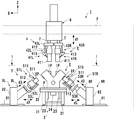
図1は本発明の一実施形態に係る試験装置1の模式図であり、図2は図1のI−I線矢視図である。図1を試験装置1の正面図とすると図2は試験装置1の一部の構成を除いた平面図に相当する。なお、図1において、搬送装置100の具体的構成は省略している。
FIG. 1 is a schematic view of a
試験装置1は、ローラコンベヤ等の搬送装置100によってX方向に搬送されるエンジンEを取り込み、その試験を行い、試験後には再び搬送装置100にエンジンEを戻す。試験装置1がエンジンEに対して行う試験は、燃料の燃焼を伴わない、擬似的な駆動状態で行う試験であり、いわゆるコールドテストを行う装置である。
The
エンジンEは、多気筒エンジンである。本発明が適用可能な多気筒エンジンは、気筒数、気筒配置に特に制約はないが本実施形態ではV型6気筒エンジンを想定している。エンジンEは気筒列方向がY方向とされて、片方のバンクに3気筒ずつ配置されている。吸気ポートIPは、気筒毎に一つずつ独立して設けられ、合計6つの吸気ポートIPがバンク間に配置されている。本実施形態の場合、排気ポートEPは集合排気ポートとしており、バンク毎に一つ、合計2つ設けられている。なお、排気ポートEPが気筒毎に一つずつ独立して構成されている場合についても本発明を適用できることはいうまでもない。 The engine E is a multi-cylinder engine. The multi-cylinder engine to which the present invention is applicable is not particularly limited in the number of cylinders and the cylinder arrangement, but in the present embodiment, a V-type 6-cylinder engine is assumed. In the engine E, the cylinder row direction is the Y direction, and three cylinders are arranged in one bank. One intake port IP is provided independently for each cylinder, and a total of six intake ports IP are arranged between the banks. In the case of this embodiment, the exhaust port EP is a collective exhaust port, and is provided in total, two for each bank. Needless to say, the present invention can also be applied to the case where the exhaust port EP is independently configured for each cylinder.
<試験装置の構成>
試験装置1は、搬送機構2、駆動ユニット3、試験ユニット4及び5、移動機構6、緩衝機構7、及び、移動機構8L、8R、9L及び9Rを備える。なお、符号の末尾につく、符号Lは図1で見て左側のバンクの試験に対応する構成を示し、符号Rは図1又は図2で見て右側のバンクの試験に対応する構成を示す。これらの符号L、Rは、これらの構成を区別する必要がない場合は省略する場合がある。例えば、移動機構8Lと移動機構8Rとを区別しない場合、単に移動機構8と示す場合がある。
<Configuration of test equipment>
The
搬送機構2は、エンジンEを搭載するパレットPをX方向に搬送する搬送装置100と、搬送装置100にて搬送されるエンジンE(パレットPに搭載)を試験装置1内に取り込み、また、試験完了後のエンジンEを搬送装置100に戻す機構、すなわち可動搬送ユニット22とで構成される。搬送装置100は、X方向に延設された一対のローラコンベア101で構成され、ワークを所定の位置で位置決めする停止装置を備える。可動搬送ユニット22は、パレットPを昇降させる昇降ユニット23と、Y方向に延設された一対のガイドローラ21と、ガイドローラ21に沿って移動自在なスライダ(図示せず)と、スライダをY方向に駆動させる駆動ユニット24とを備える。駆動ユニット24としては、例えば、ボールネジユニット、リニアモータユニットなどの公知のリニア駆動ユニットが挙げられる。また、ガイドローラ21としては、例えば、フリーローラが挙げられる。
The
試験対象であるエンジンEはパレットPに搭載されて搬送装置100上を搬送される。可動搬送ユニット22上にエンジンEを搭載したパレットPが到達すると、停止装置によりパレットPが所定の位置に位置決め、固定される。その後、駆動ユニット24によりスライダがパレットPとの係合位置にスライドされると共に、昇降ユニット23によりパレットPが上昇する。これにより、パレットPがスライダの下側凹部に潜り込んでパレットPと連結される。その後、駆動ユニット24によりスライダが試験装置1側にスライドされる。
The engine E to be tested is mounted on the pallet P and is transported on the
スライダは、パレットPと共にエンジンEを試験位置(図2で破線で示すエンジンEの位置)まで搬送し、試験中、そのまま待機する。試験が終了後、再び駆動ユニット24によりスライダをパレットP側にスライドさせ、パレットPを搬送装置100へ移載し、搬送する。こうして、連続的にエンジンEの試験が可能である。
The slider conveys the engine E together with the pallet P to the test position (the position of the engine E indicated by a broken line in FIG. 2), and waits as it is during the test. After the test is completed, the slider is again slid to the pallet P side by the
駆動ユニット3は、電動モータ等の駆動源31と、駆動源31により回転されるチャック32とを備える。エンジンEが試験位置に到達すると、チャック32によりエンジンEのクランク軸と駆動源31とが連結される。駆動源31を駆動することによりクランク軸が回転し、エンジンEを擬似的な駆動状態とすることができる。
The drive unit 3 includes a
試験ユニット4及び5は、エンジンEを擬似的な駆動状態とした場合における吸気ポートIP、排気ポートEPの圧力変動を計測するユニットである。
The
試験ユニット4は、図1に示すように、左側のバンクの三つの吸気ポートIPに対応する複数の圧力検査ユニット41L(詳細は後述する。)、一つの開閉機構42L及び一つの支持ユニット43Lと、右側のバンクの三つの吸気ポートIPに対応する複数の圧力検査ユニット41R、一つの開閉機構42R及び一つの支持ユニット43Rと、を備えている。
As shown in FIG. 1, the test unit 4 includes a plurality of
試験ユニット5は、図1で見て左側のバンクの一つの排気ポートEPに対応する一つの圧力検査ユニット51L(詳細は後述)、一つの開閉機構52L及び一つの支持ユニット53Lと、右側のバンクの一つの排気ポートEPに対応する一つの圧力検査ユニット51R、一つの開閉機構52R及び一つの支持ユニット53Rと、を備えている。
The
移動機構6は、緩衝機構7を介して試験ユニット4を移動させる。本実施形態においては、吸気ポートIPがエンジンEの上部において略上向きに開口した配置した場合を例に挙げている。このため、本実施形態では移動機構6は図1で矢印d1で示すように試験ユニット4を昇降させる昇降機構であり、試験ユニット4を検査位置と退避位置との間で移動させる。検査位置とは圧力検査ユニット41が備える配管411が吸気ポートIPに接続される位置であり、退避位置とは配管411が吸気ポートIPから離間した位置である。エンジンEを搬送装置100から試験装置1へと取り込む場合、試験ユニット4は退避位置に移動され、エンジンEの収容空間が確保される。試験を行う場合には、試験ユニット4は検査位置に移動され、配管411が吸気ポートIPに接続される。
The moving
移動機構8L、9Lは支持ユニット53Lを移動させる機構であり、移動機構8R、9Rは支持ユニット53Rを移動させる機構である。圧力検査ユニット51及び開閉機構52は支持ユニット53に搭載されている。移動機構8及び9は支持ユニット53を移動することで、圧力検査ユニット51及び開閉機構52を検査位置と退避位置との間で移動させる。図1及び図2は、圧力検査ユニット51Lが退避位置にあり、圧力検査ユニット51Rが検査位置にある場合を例示している。検査位置とは、圧力検査ユニット51が備える配管511の先端が排気ポートEPに接続される位置であり、退避位置とは配管511が排気ポートEPから離間した位置である。
The moving
排気ポートEPはバンクの外壁に開口しており、外壁は斜め下向きに傾斜している。移動機構8は、矢印d3で示すように、バンクの外壁に略直交する方向に支持ユニット53を進退させる。移動機構9はX方向に延設された一対のレール91と、レール91の案内により移動するスライダ92とを備える。移動機構8はスライダ92に搭載されており、移動機構9によってX方向に移動される。つまり、支持ユニット53はX方向と斜め方向との2方向に移動される。
The exhaust port EP opens to the outer wall of the bank, and the outer wall is inclined obliquely downward. The moving mechanism 8 advances and retracts the support unit 53 in a direction substantially orthogonal to the outer wall of the bank as indicated by an arrow d3. The moving mechanism 9 includes a pair of
移動機構8は例えばエアシリンダや電動シリンダから構成することができる。移動機構9は、例えば、モータ等の駆動源と、駆動源の駆動力を伝達する伝達機構(例えば、ベルト伝達機構、ボールネジ機構、ラック−ピニオン機構等)と、から構成することができる。また、移動機構9は、エアシリンダや電動シリンダ等で構成しても良い。 The moving mechanism 8 can be composed of, for example, an air cylinder or an electric cylinder. The moving mechanism 9 can be composed of, for example, a driving source such as a motor and a transmission mechanism (for example, a belt transmission mechanism, a ball screw mechanism, a rack-pinion mechanism, etc.) that transmits the driving force of the driving source. Further, the moving mechanism 9 may be constituted by an air cylinder, an electric cylinder or the like.
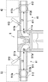
<圧力検査ユニット>
圧力検査ユニット41、51及び従来の課題について図3を参照して説明する。同図は圧力検査ユニット41、51による試験時の態様を示しており、圧力検査ユニット41、51は検査位置に位置している。なお、本実施形態の場合、上記のとおり、排気ポートEPは集合排気ポートである場合を想定しているが、説明を簡単にするため、図3においては、図形上、気筒毎の排気ポートとして示している。
<Pressure inspection unit>
The
圧力検査ユニット41は、吸気ポートIP毎に一つずつ設けられる。本実施形態の場合、吸気ポートIPは六つ設けられているので、圧力検査ユニット41も六つ設けられている。圧力検査ユニット41は、配管411と、バルブ412と、圧力センサ413と、を備える。
One
配管411は、吸気ポートIPに接続され、その内部空間が吸気ポートIPに連通する。配管411は、例えば金属製の筒状部材から構成されるが、その先端部411aに、吸気ポートIPの開口周縁に気密に密接するよう、ゴム等のシール材を設けてもよい。
The
配管411の周壁には、圧力センサ413を取り付けられる取付部411bが設けられている。取付部411bは、吸気ポートIPとバルブ412との間の位置に形成されている。取付部411bは、圧力センサ413がネジ等で締結されるボス部に、配管411の内部空間と連通する貫通孔を形成したものであり、圧力センサ413の検知部はこの貫通孔に気密に挿入される。圧力センサ413は気圧を計測するセンサであり、配管411の内部空間の圧力を検出する。
The peripheral wall of the
バルブ412の開閉により、配管411の断面開口を開放/閉塞する。開放時には吸気ポートIPが大気と連通状態となり、閉塞時には吸気ポートIPが大気と非連通状態となる。バルブ412は、本実施形態の場合、ボールバルブを想定している。バルブ412は操作部412aと、球状の弁体412bとを備える。本実施形態の場合、操作部412aは、弁体412bに接続された弁軸であり、操作部412aをその軸周りに回転させることで弁体412bが回転し、バルブ412が開閉される。操作部412a及び弁体412bの回転範囲は90度を想定しており、操作部412aを90度回転させることで弁体412bを開状態と閉状態とで切り替えることができる。操作部412aの回転は、操作部412aに接続される開閉機構42により行われる。この開閉機構42の駆動により、操作部412aが回転され、バルブ412が開閉される。開閉機構42は後述する通りである。
By opening and closing the
圧力検査ユニット51は、排気ポートEP毎に一つずつ設けられる。本実施形態の場合、排気ポートEPは二つ設けられているので、圧力検査ユニット51も二つ設けられている。圧力検査ユニット51は、圧力検査ユニット41と同様の構成である。
One
圧力検査ユニット51は、配管511と、バルブ512と、圧力センサ513と、を備える。配管511は、排気ポートEPに接続され、その内部空間が排気ポートEPに連通する。配管511は、例えば金属製の筒状部材から構成されるが、その先端部511aは、排気ポートEPの開口周縁に気密に密接するよう、ゴム等のシール材料から構成することができる。
The
配管511の周壁には、圧力センサ513が取付けられる取付部511bが設けられている。取付部511bは、排気ポートEPとバルブ512との間の位置に形成されている。取付部511bは、圧力センサ513がネジ等で締結されるボス部に、配管511の内部空間と連通する貫通孔を形成したものであり、圧力センサ513の検知部はこの貫通孔に気密に挿入される。圧力センサ513は気圧を計測するセンサであり、配管511の内部空間の圧力を検出する。
An
バルブ512の開閉により、配管511の断面開口を開放/閉塞する。開放時には排気ポートEPが大気と連通状態となり、閉鎖時には排気ポートEPが大気と非連通状態となる。バルブ512は、本実施形態の場合、ボールバルブを想定している。バルブ512は操作部512aと、球状の弁体512bとを備える。本実施形態の場合、操作部512aは、弁体512bに接続された弁軸であり、操作部512aをその軸周りに回転させることで弁体512bが回転し、バルブ512が開閉される。操作部512a及び弁体512bの回転範囲は90度を想定しており、操作部512aを90度回転させることで弁体512bを開状態と閉状態とで切り替えることができる。操作部512aの回転は、操作部512aに接続される開閉機構52により行われる。この開閉機構52の駆動により、操作部512aが回転され、バルブ512が開閉される。開閉機構52は後述する通りである。
By opening and closing the
エンジンEの試験においては、例えば、バルブ412を開状態と、バルブ512を閉状態とし、駆動ユニット3の駆動によりエンジンEを擬似的な駆動状態とする。そして、圧力センサ513により排気ポートEPの圧力変動を計測する。また、例えば、バルブ412を閉状態とし、バルブ512を開状態とし、駆動ユニット3の駆動によりエンジンEを擬似的な駆動状態とする。そして、圧力センサ413により吸気ポートIPの圧力変動を計測する。
In the test of the engine E, for example, the
各ポートの圧力変動をより瞬時に計測するためには、より高い圧力が必要であり、これは、各ポート内の容積と、配管411、511の内部空間の容積に依存し、配管411、511の内部空間の容積をできるだけ小さくすることが有効となる。つまり、吸気ポートIPからバルブ412までの配管長L1及び排気ポートEPからバルブ512までの配管長L2をより短くすることが有効である。
In order to measure the pressure fluctuation of each port more instantaneously, a higher pressure is required, which depends on the volume in each port and the volume of the internal space of the
配管長L1、L2を短くするためには、バルブ412、512を吸気ポートIP、排気ポートEPに近づける必要がある。しかし、バルブ412と吸気ポートIPとの間には、圧力センサ413が存在し、また、開閉機構42の配置スペースを確保する必要がある。同様に、バルブ512と排気ポートEPとの間には、圧力センサ513が存在し、また、開閉機構52の配置スペースを確保する必要がある。
In order to shorten the pipe lengths L1 and L2, it is necessary to bring the
ボールバルブは、一般に、開放時に抵抗が小さく、閉塞時にはシール性が高いことから、この種の試験に有効である。ただし、シール性が高い分、開閉に必要な作動トルクが比較的高く、駆動源となるアクチュエータが大型のものとなる。また、開閉機構42は、その作動トルクが大きく、使用頻度が高い程、大きさが大きくなる傾向にあり、小型化が難しい機構である。よって、ボールバルブを開閉するアクチュエータを、ボールバルブ毎に設けた一般的な構成においては、アクチュエータの配設スペースを広く確保する必要があり、配管長L1、L2を短くするのに限界がある。
Ball valves are generally effective for this type of test because they have a low resistance when opened and a high sealing property when closed. However, since the sealing performance is high, the operating torque required for opening and closing is relatively high, and the actuator serving as the drive source is large. The opening /
本実施形態は、アクチュエータをバルブから離して配置し、伝達機構を介して駆動力を伝達させる。これによりバルブの開閉の自動化を可能とし、かつ、配管長をより短くすることができる。以下、開閉機構42の構成を中心に吸気側の構成(試験ユニット4、移動機構6及び緩衝機構7)について説明する。
In the present embodiment, the actuator is disposed away from the valve, and the driving force is transmitted via the transmission mechanism. Thereby, the opening and closing of the valve can be automated, and the pipe length can be further shortened. Hereinafter, the configuration on the intake side (the test unit 4, the moving
<吸気側の構成>
図1、図4〜図6を参照して、試験ユニット4、移動機構6及び緩衝機構7の構成について説明する。図4は試験ユニット4及び移動機構6の斜視図であり、図5は試験ユニット4及びその周辺の斜視図である。図6は試験ユニット4の下部の説明図であり、一部破断図である。
<Intake side configuration>
The configuration of the test unit 4, the moving
移動機構6は、アクチュエータ61と、昇降体62と、支持体63とを備える。アクチュエータ61は、例えば、電動シリンダやエアシリンダであり、ロッド61aを進退させることで、昇降体62を昇降する。昇降体62には緩衝機構7を介して試験ユニット4が接続されている。試験ユニット4は、緩衝機構7を介して昇降体62に吊り下げられており、昇降体62の昇降によって昇降する。支持体63は、試験装置1の骨格を構成するフレームF(図1)に固定されると共に、昇降体62の昇降を案内する。
The moving
緩衝機構7は、試験ユニット4の支持ユニット43と、移動機構6の昇降体62との間に設けられ、これらの相対位置を変位可能に接続する。本実施形態の場合、4つの緩衝機構7が設けられており、そのうちの二つは支持ユニット43Lと昇降体62との間に設けられ、残りの二つは支持ユニット43Rと昇降体62との間に設けられている。したがって、昇降体62に対して、支持ユニット43Rと支持ユニット43Lとは、それぞれ独立してZ方向に相対変位可能になっている。昇降体62は、緩衝機構7が取付けられる取付部62aを四つ備えている。支持ユニット43Lは、三つの圧力検査ユニット41Lと、開閉機構42Lとを支持する。支持ユニット43Rは、三つの圧力検査ユニット41Rと開閉機構42Rとを支持する。支持ユニット43の昇降により圧力検査ユニット41、開閉機構42も昇降する。
The
緩衝機構7は、ロッド71と、弾性部材72と、ストッパ73とを備える。ロッド71はZ方向に延設された軸であり、その下端部には支持ユニット43が固定されている。また、ロッド71の上端部は、昇降体62の一部に接続される。取付部62aにはロッド71が挿通する貫通孔が形成されており、ロッド71はこの貫通孔を挿通して取付部62aの上方まで延設されている。
The
ストッパ73は取付部62aよりも上方の部位においてロッド71に固定されている。ストッパ73は、昇降体62に対する支持ユニット43の最大離間距離を規定する。すなわち、支持ユニット43が昇降体62に対して降下するとロッド71も支持ユニット43と共に降下するが、ストッパ73が取付部62aと係合することで、支持ユニット43及びロッド71の降下が規制されることになる。
The
弾性部材72は、取付部62aと支持ユニット43との間に介在しており、昇降体62と支持ユニット43とを、これらが離間する方向に常時付勢する。本実施形態の場合、弾性部材72はコイルスプリングであり、ロッド71は弾性部材72を挿通している。
The
試験ユニット4を検査位置に移動する場合、移動機構6は昇降体62を降下させる。吸気ポートIPの配置との関係で、図6に示すように、配管411はZ方向に延設されており、その先端部411aは配管411の下端部となっている。配管411の先端部411aが吸気ポートIPの開口周縁に当接する際、昇降体62に対して試験ユニット4がZ方向に相対変位可能であることから、先端部411aと吸気ポートIPの開口周縁との当接時の衝撃が緩衝される。また、弾性部材72の付勢により、先端部411aを吸気ポートIPの開口周縁に押し付けて気密性を向上できる。
When moving the test unit 4 to the inspection position, the moving
加えて、試験ユニット4をロッド71、ストッパ73を介して昇降体62に接続する構成としたので、エンジンEの機種変更に伴って試験ユニット4を交換する場合にも、昇降体62と試験ユニット4との分離が容易化し、交換作業を円滑に行える。また、弾性部材72を設けたことにより、交換後の試験ユニット4のテスト動作の際、配管411と吸気ポートIPの開口周縁との当接時の力加減が自動調整されるので、試験に必要な各種の動作設定も容易化する。なお、このような緩衝機構は、試験ユニット5と移動機構8との間にも設けてもよい。
In addition, since the test unit 4 is connected to the elevating
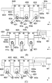
次に、開閉機構42の構成について説明する。開閉機構42は本実施形態の場合、エンジンEの気筒列毎(片バンク毎)に設けられている。開閉機構42Lは、図1及び図2で見て左側のバンクに対応し、開閉機構42Rは右側のバンクに対応している。開閉機構42Lと開閉機構42Rとは同様の構成である。以下、図4〜図8を参照して開閉機構42の構成について説明する。図7は試験ユニット4の下部の説明図であり、開閉機構42の一部破断図である。図8(A)〜(C)は開閉機構42の動作説明図である。
Next, the configuration of the opening /
開閉機構42は、アクチュエータ421と、伝達機構422と、を備える。アクチュエータ421は駆動力を出力し、伝達機構422はアクチュエータ421に接続されてその駆動力を複数のバルブ412(本実施形態では三つのバルブ412)の各操作部412aに伝達する。
The opening /
アクチュエータ421は、一つの開閉機構42に一つ設けられている。つまり、開閉機構42L、42Rは、それぞれ一つのアクチュエータ421を備える。
One
アクチュエータ421は、本実施形態の場合、エアシリンダや電動シリンダであり、気筒列方向(Y方向)に延設されると共に、気筒列方向(Y方向)に進退するロッド421aを備える。アクチュエータ421は、気筒列方向(Y方向)で見て、試験ユニット4の一端側に配置されている。配管411との関係でみると、配管411の配列方向で一端側に配管411から離れて配置されている。このように本実施形態ではアクチュエータ421の配設スペースが配管長L1、L2(図3)に影響しない構成としている。
In the present embodiment, the
伝達機構422は、本実施形態の場合、アクチュエータ421を駆動源としたリンク機構を構成している。伝達機構422は、ハンドル部材4221と、スライド部材4222と、リンク部材4223と、レール部材4224とを備える。ハンドル部材4221とリンク部材4223とは、バルブ412毎に設けられている。したがって、開閉機構42Lのハンドル部材4221とリンク部材4223はそれぞれ三つであり、開閉機構42Rのハンドル部材4221とリンク部材4223もそれぞれ三つである。
In this embodiment, the
スライド部材4222とレール部材4224は、一つの開閉機構42に一つ設けられている。したがって、開閉機構42Lのスライド部材4222とレール部材4224はそれぞれ一つであり、開閉機構42Rのスライド部材4222とレール部材4224もそれぞれ一つである。
One
図8に示すように、ハンドル部材4221は、その一方端部に操作部412aが接続され、操作部412aの軸方向と直交する方向に延びる板状の部材である。ハンドル部材4221を操作部412aの軸方向周りに回動させることで操作部412aが回転し、弁体412bが回転する。ハンドル部材4221の他方端部には円柱形状の係合部4221aが設けられている。係合部4221aは例えば、回転自在にハンドル部材4221に固定されたローラである。
As shown in FIG. 8, the
スライド部材4222及びレール部材4224は、気筒列方向(Y方向)に延設されている。レール部材4224は支持ユニット43に支持されており、スライド部材4222の気筒列方向(Y方向)の移動を案内する。スライド部材4222は、レール部材4224の上側に設けられ、レール部材4224と係合すると共に気筒列方向(Y方向)にスライド自在となっている。
The
スライド部材4222の一端には接続部4222aが設けられており、この接続部4222aにはロッド421aの先端が固定されている。アクチュエータ421の駆動により、ロッド421aが進退駆動すると、その駆動力が伝達されてスライド部材4222が気筒列方向(Y方向)に移動することになる。
A
一つのスライド部材4222には、三つのリンク部材4223が連結されている。リンク部材4223は、スライド部材4222と固定される垂直な板状の上部と、係合部4223aを備える垂直な板状の下部と、上部と下部を接続する水平な板状の中間部とを備える。係合部4223aは本実施形態の場合、下方に開口した溝であり、リンク部材4223の下部はカニ爪形状或いはスパナ形状を呈している。ハンドル部材4221の係合部4221aは、係合部4223aに挿入されて互いに係合する。なお、逆の構成として、ハンドル部材4221の係合部4221aをカニ爪形状或いはスパナ形状に置換し、リンク部材4223に係合部4221aに相当するローラとしても構わない。
Three
なお、リンク部材4223と、スライド部材4222及びリンク部材4223との連結構造は上述した構成に限られず、様々な構成が採用可能である。
Note that the connection structure of the
図8(A)〜(C)を参照して開閉機構42によるバルブ412の開閉動作について説明する。図8(A)は例えば、バルブ412を閉じているときの開閉機構42の態様を示している。アクチュエータ421の駆動により、ロッド421aが前進するとスライド部材4222がY方向(図8中では左方向)にスライドし、スライド部材4222に連結されている三つのリンク部材4223がY方向に平行移動する。
The opening / closing operation of the
このとき、ハンドル部材4221の係合部4221aは、係合部4223aの溝に沿って移動案内されて溝奥側に移動し、図8(B)に示すようにハンドル部材4221を操作部412aを中心として回動させる。こうして、リンク部材4223はスライド部材4222のスライドに連動してハンドル部材4221を操作部412aの軸周りに回動させ、操作部412aを回転させることになる。この結果、弁体412bも回転する。
At this time, the engaging
スライド部材4222のスライド量に比例してハンドル部材4221が回動し、ハンドル部材4221が図8(A)の状態から90度回動すると図8(C)の状態となる。この時、バルブ412は開放状態となる。アクチュエータ421の駆動により、ロッド421aを後退させると、図8(C)の状態から図8(A)の状態に戻ることができる。三つのバルブ412はバンク毎にそれぞれ同時に開閉される。
When the
こうして本実施形態ではバルブ412の開閉の自動化が可能である。アクチュエータ421は、スライド部材4222の気筒列方向(Y方向)の一端部側に配置されており、配管411の配列方向で一端側に配管411から離れて配置されているので、その配設スペースが配管長L1、L2(図3)に影響しない。したがって、バルブ412の開閉に必要なトルクが増大したり、開閉回数の増加に伴ってより高い耐久性が必要とされる場合に、アクチュエータ421を大型化せざる得ない場合であっても、配管長L1、L2への影響を考慮する必要がなく、設計の自由度が向上する。
Thus, in this embodiment, the opening and closing of the
その結果、図6に示すように、本実施形態では、バルブ412と圧力センサ413とが配管411の長手方向に直交する方向(ここでは水平方向)に隣接する構成としており、配管長L1、L2(図3)がより短くなる構成を実現している。
As a result, as shown in FIG. 6, in this embodiment, the
伝達機構422は、バルブ412の周辺の構成であるハンドル部材4221とリンク部材4223とを板状の部材で構成し、これらの専有スペースを小さくしている。特に、リンク部材4223は、上部、中間部及び下部をクランク状に折曲して形成し、バルブ412に隣接する部分を係合部4223aを備える下部のみとしている。この結果、ハンドル部材4221とリンク部材4223の下部とをバルブ412と圧力センサ413との隙間(狭い空間)に配置した構成を実現している。
In the
<排気側の構成>
開閉機構52は、開閉するバルブの数が一つである点で開閉機構42と異なるが、他は同様の構成とすることができる。例えば、開閉機構52は、開閉機構42において、ハンドル部材4221とリンク部材4223を一つとし、その他は同じ構成とすることができる。本実施形態で想定した集合排気ポートを採用せず、片バンクに排気ポートEPを複数設けた構成の場合、開閉機構52は開閉機構42と同様の構成とすることができる。
<Exhaust side configuration>
The opening /
Claims (8)
複数の圧力検査ユニットと、
少なくとも一つの開閉機構と、を備え、
前記複数の圧力検査ユニットは、それぞれ、
前記複数のポートのうちの一つに接続される配管と、
前記配管を開閉するバルブと、を備え、
前記配管は、前記吸気ポート又は前記排気ポートと前記バルブとの間の位置に設けられ、前記配管内の圧力を検出するセンサが取り付けられる取付部を備え、
前記開閉機構は、
一つのアクチュエータと、
前記アクチュエータに接続され、前記アクチュエータの駆動力を複数の前記バルブの各操作部に伝達して、前記複数のバルブを開閉する伝達機構と、を備え、
前記伝達機構は、
前記アクチュエータの駆動により、気筒列方向にスライド自在なスライド部材と、
複数の前記バルブの各操作部に一方端部がそれぞれ接続されるハンドル部材と、
先端側が該ハンドル部材の他方端部にそれぞれ係合され、根元側が前記スライド部材にそれぞれ固定されるリンク部材と、を備える、
ことを特徴とする試験ユニット。 A test unit for testing a multi-cylinder engine having a plurality of ports including an intake port and an exhaust port in a simulated driving state,
Multiple pressure testing units;
And at least one opening and closing mechanism,
Each of the plurality of pressure inspection units includes:
Piping connected to one of the plurality of ports;
A valve for opening and closing the pipe,
The pipe is provided at a position between the intake port or the exhaust port and the valve, and includes a mounting portion to which a sensor for detecting a pressure in the pipe is attached.
The opening and closing mechanism is
One actuator,
Which is connected to the actuator, and transmits the driving force of the actuator to the operating portion of the plurality of valves, Bei example and a transmission mechanism for opening and closing said plurality of valves,
The transmission mechanism is
A sliding member that is slidable in the cylinder row direction by driving the actuator;
A handle member having one end connected to each operation portion of the plurality of valves;
A distal end side is engaged with the other end portion of the handle member, and a base side is provided with a link member fixed to the slide member, respectively.
A test unit characterized by that.
複数の前記リンク部材はクランク形に折り曲げて設けられ、上部、中間部、及び下部を備え、該下部が前記係合部を備える、
ことを特徴とする試験ユニット。 The test unit according to claim 1,
The plurality of link members are provided to be bent in a crank shape, and include an upper portion, an intermediate portion, and a lower portion, and the lower portion includes the engaging portion.
A test unit characterized by that .
前記取付部に設けられ、前記配管内の圧力を検出するセンサを備える、
ことを特徴とする試験ユニット。 The test unit according to claim 1,
Provided with a sensor for detecting a pressure in the pipe provided in the mounting portion;
A test unit characterized by that .
前記複数のポートは、複数の吸気ポートを含み、
前記複数の圧力検査ユニットの各圧力検査ユニットは、前記複数の吸気ポートの各吸気ポートに設けられ、
前記開閉機構は気筒列毎に設けられる、
ことを特徴とする試験ユニット。 The test unit according to any one of claims 1 to 3 ,
The plurality of ports includes a plurality of intake ports,
Each pressure inspection unit of the plurality of pressure inspection units is provided in each intake port of the plurality of intake ports,
The opening / closing mechanism is provided for each cylinder row,
A test unit characterized by that.
前記操作部は弁軸であり、
前記ハンドル部材は、前記弁軸に接続され、
前記リンク部材は、前記スライド部材のスライドに連動して前記ハンドル部材を前記弁軸周りに回動させ、
前記アクチュエータは、前記スライド部材の気筒列方向の一端部側に配置され、前記スライド部材を前記気筒列方向に付勢する、
ことを特徴とする試験ユニット。 The test unit according to any one of claims 1 to 4 ,
The operating portion is a valve stem;
The handle member is connected to the valve stem ;
The link member rotates the handle member around the valve shaft in conjunction with the slide of the slide member ,
The actuator is disposed on one end side in the cylinder row direction of the slide member, and biases the slide member in the cylinder row direction.
A test unit characterized by that.
前記複数の圧力検査ユニットを支持する支持ユニットと、
前記配管が前記ポートに接続される検査位置と、前記配管が前記ポートから離間した退避位置との間で、前記支持ユニットを移動させる移動機構と、を備える、
ことを特徴とする試験ユニット。 The test unit according to any one of claims 1 to 3,
A support unit for supporting the plurality of pressure inspection units;
A moving mechanism for moving the support unit between an inspection position where the pipe is connected to the port and a retracted position where the pipe is separated from the port;
A test unit characterized by that.
複数の圧力検査ユニットと、
少なくとも一つの開閉機構と、を備え、
前記複数の圧力検査ユニットは、それぞれ、
前記複数のポートのうちの一つに接続される配管と、
前記配管内の圧力を検出するセンサと、
前記配管を開閉するバルブと、を備え、
前記試験装置は、
前記複数の圧力検査ユニットを支持する支持ユニットと、
前記配管が前記ポートに接続される検査位置と、前記配管が前記ポートから離間した退避位置との間で、前記支持ユニットを移動させる移動機構と、
前記支持ユニットと前記移動機構との間に設けられ、これらの相対位置を変位可能に接続する緩衝機構と、を更に備え、
前記開閉機構は、
一つのアクチュエータと、
前記アクチュエータに接続され、前記アクチュエータの駆動力を複数の前記バルブの各操作部に伝達して、前記複数のバルブを開閉する伝達機構と、を備える、
ことを特徴とする試験装置。 A test apparatus for testing a multi-cylinder engine having a plurality of ports including an intake port and an exhaust port in a pseudo drive state,
Multiple pressure testing units;
And at least one opening and closing mechanism,
Each of the plurality of pressure inspection units includes:
Piping connected to one of the plurality of ports;
A sensor for detecting the pressure in the pipe;
A valve for opening and closing the pipe,
The test apparatus comprises:
A support unit for supporting the plurality of pressure inspection units;
A moving mechanism for moving the support unit between an inspection position where the pipe is connected to the port and a retracted position where the pipe is separated from the port;
Said support unit and provided between said moving mechanism further example Preparations and buffer mechanism, a connecting these relative positions displaceably,
The opening and closing mechanism is
One actuator,
A transmission mechanism that is connected to the actuator and transmits a driving force of the actuator to each operation unit of the plurality of valves to open and close the plurality of valves.
A test apparatus characterized by that.
複数の圧力検査ユニットと、
少なくとも一つの開閉機構と、を備え、
前記複数の圧力検査ユニットは、それぞれ、
前記複数のポートのうちの一つに接続される配管と、
前記配管内の圧力を検出するセンサと、
前記配管を開閉するバルブと、を備え、
前記試験装置は、
前記複数の圧力検査ユニットを支持する支持ユニットと、
前記配管が前記ポートに接続される検査位置と、前記配管が前記ポートから離間した退避位置との間で、前記支持ユニットを昇降させる昇降機構と、
前記支持ユニットと前記昇降機構との間に設けられ、これらの相対位置を変位可能に接続する緩衝機構と、を更に備え、
前記開閉機構は、
一つのアクチュエータと、
前記アクチュエータに接続され、前記アクチュエータの駆動力を複数の前記バルブの各操作部に伝達して、前記複数のバルブを開閉する伝達機構と、を備える、
ことを特徴とする試験装置。 A test apparatus for testing a multi-cylinder engine having a plurality of ports including an intake port and an exhaust port in a pseudo drive state,
Multiple pressure testing units;
And at least one opening and closing mechanism,
Each of the plurality of pressure inspection units includes:
Piping connected to one of the plurality of ports;
A sensor for detecting the pressure in the pipe;
A valve for opening and closing the pipe,
The test apparatus comprises:
A support unit for supporting the plurality of pressure inspection units;
A test position in which the pipe is connected to the port, the lifting mechanism the pipe between a retracted position spaced from said port, for elevating the support unit,
Said support unit and disposed between said lifting mechanism further example Preparations and buffer mechanism, a connecting these relative positions displaceably,
The opening and closing mechanism is
One actuator,
A transmission mechanism that is connected to the actuator and transmits a driving force of the actuator to each operation unit of the plurality of valves to open and close the plurality of valves.
A test apparatus characterized by that.
Priority Applications (4)
| Application Number | Priority Date | Filing Date | Title |
|---|---|---|---|
| JP2014066733A JP6276085B2 (en) | 2014-03-27 | 2014-03-27 | Test equipment and test unit |
| US14/670,052 US9804056B2 (en) | 2014-03-27 | 2015-03-26 | Testing unit for testing a multi-cylinder engine |
| CN201510140473.6A CN104949837A (en) | 2014-03-27 | 2015-03-27 | Testing device and testing unit |
| EP15000906.6A EP2924413B1 (en) | 2014-03-27 | 2015-03-27 | Engine component testing device |
Applications Claiming Priority (1)
| Application Number | Priority Date | Filing Date | Title |
|---|---|---|---|
| JP2014066733A JP6276085B2 (en) | 2014-03-27 | 2014-03-27 | Test equipment and test unit |
Publications (3)
| Publication Number | Publication Date |
|---|---|
| JP2015190797A JP2015190797A (en) | 2015-11-02 |
| JP2015190797A5 JP2015190797A5 (en) | 2017-04-06 |
| JP6276085B2 true JP6276085B2 (en) | 2018-02-07 |
Family
ID=52823428
Family Applications (1)
| Application Number | Title | Priority Date | Filing Date |
|---|---|---|---|
| JP2014066733A Expired - Fee Related JP6276085B2 (en) | 2014-03-27 | 2014-03-27 | Test equipment and test unit |
Country Status (4)
| Country | Link |
|---|---|
| US (1) | US9804056B2 (en) |
| EP (1) | EP2924413B1 (en) |
| JP (1) | JP6276085B2 (en) |
| CN (1) | CN104949837A (en) |
Families Citing this family (5)
| Publication number | Priority date | Publication date | Assignee | Title |
|---|---|---|---|---|
| CN105223024A (en) * | 2015-11-09 | 2016-01-06 | 攀钢集团矿业有限公司 | For the testing table of engine thermal break-in |
| KR101819896B1 (en) * | 2016-12-01 | 2018-02-28 | (주)모토닉 | Apparatus and Method for testing engine CVV duration mechanism |
| BR112018014224B1 (en) * | 2017-03-31 | 2022-12-06 | Hirata Corporation | ENGINE TESTING DEVICE |
| CN111337271A (en) * | 2020-03-31 | 2020-06-26 | 昆山顺扬工业成套设备有限公司 | Oval car strength testing device |
| US11635349B1 (en) * | 2021-11-30 | 2023-04-25 | Honda Motor Co., Ltd. | Valve testing apparatus |
Family Cites Families (12)
| Publication number | Priority date | Publication date | Assignee | Title |
|---|---|---|---|---|
| JPS5759342U (en) * | 1980-09-25 | 1982-04-08 | ||
| JPH0721638Y2 (en) * | 1992-03-03 | 1995-05-17 | 有限会社トシヒロ産業 | Interlocking switching valve |
| JP2724942B2 (en) * | 1992-07-06 | 1998-03-09 | 本田技研工業株式会社 | Engine valve timing measurement device |
| US5417109A (en) * | 1993-09-30 | 1995-05-23 | Lucas Automation & Control Engineering, Inc. | Methods and apparatus for testing engines |
| US5492006A (en) * | 1993-11-29 | 1996-02-20 | Bauer Associates, Inc. | Method of testing internal combustion engine |
| JP3624589B2 (en) * | 1996-11-21 | 2005-03-02 | トヨタ自動車株式会社 | Engine inspection method |
| US6481269B2 (en) | 1996-07-19 | 2002-11-19 | Toyota Jidosha Kabushiki Kaisha | Method of testing assembled internal combustion engine |
| JP3122391B2 (en) * | 1997-07-01 | 2001-01-09 | 三菱重工業株式会社 | Multi-valve interlocking switching device |
| JP3906833B2 (en) | 2003-10-14 | 2007-04-18 | マツダ株式会社 | Engine exhaust pressure detector |
| JP4315957B2 (en) | 2003-12-12 | 2009-08-19 | 平田機工株式会社 | Engine motoring test equipment |
| JP4827902B2 (en) | 2008-09-08 | 2011-11-30 | 平田機工株式会社 | Method and apparatus for measuring and adjusting valve clearance |
| CN102022142B (en) | 2009-09-23 | 2013-09-11 | 上海电气电站设备有限公司 | Built-in steam extraction controlling and regulating valve set for steam turbine |
-
2014
- 2014-03-27 JP JP2014066733A patent/JP6276085B2/en not_active Expired - Fee Related
-
2015
- 2015-03-26 US US14/670,052 patent/US9804056B2/en not_active Expired - Fee Related
- 2015-03-27 EP EP15000906.6A patent/EP2924413B1/en not_active Not-in-force
- 2015-03-27 CN CN201510140473.6A patent/CN104949837A/en active Pending
Also Published As
| Publication number | Publication date |
|---|---|
| US9804056B2 (en) | 2017-10-31 |
| EP2924413A1 (en) | 2015-09-30 |
| EP2924413B1 (en) | 2017-08-09 |
| CN104949837A (en) | 2015-09-30 |
| US20150276551A1 (en) | 2015-10-01 |
| JP2015190797A (en) | 2015-11-02 |
Similar Documents
| Publication | Publication Date | Title |
|---|---|---|
| JP6276085B2 (en) | Test equipment and test unit | |
| JP4827902B2 (en) | Method and apparatus for measuring and adjusting valve clearance | |
| US7849734B2 (en) | Test equipment of engine motoring | |
| JP5563718B2 (en) | Piston supply device and piston supply method | |
| US8467989B2 (en) | Clearance measuring method and measuring unit | |
| TWM469491U (en) | Inspection device with dual-axis positioning mechanism | |
| KR102088788B1 (en) | Engine test device | |
| KR20160053232A (en) | Apparatus for detecting defective camshaft | |
| CN105378237A (en) | Modular system for checking a valve seat and a valve guide in cylinder heads of internal combustion engines | |
| CN110017947A (en) | A kind of airtight leakage detection apparatus of girth joint being compatible with more specification inner liners and detection method | |
| CN106855382B (en) | A kind of ammunition fuze automatically tightens measuring apparatus | |
| KR20150070878A (en) | Valve clearance measurement apparatus for engine | |
| CN209639908U (en) | A kind of airtight leakage detection apparatus of girth joint being compatible with more specification inner liners | |
| KR20190072982A (en) | Can container leakage inspection system | |
| KR101129056B1 (en) | Apparatus for inspection of the internal diameter of small sized compression spring | |
| CN111972703A (en) | Modularized cigarette appearance detection device | |
| CN214503665U (en) | Valve rotating speed detection device | |
| KR100246299B1 (en) | Automatic inspection device of valve face of engine | |
| CN218538456U (en) | Rotary conveying mechanism | |
| KR101999816B1 (en) | Valve clearance measuring apparatus | |
| CN220334045U (en) | Automatic feeding and discharging detection production line | |
| CN209673064U (en) | A kind of length automatic detection device of copper pipe | |
| CN109458896B (en) | Adjustment mechanism and spline ring gauge detection device | |
| KR100683240B1 (en) | Pace flicker automatic tester of engine valve | |
| KR101380915B1 (en) | Engine valve clearance measuring method and its apparatus |
Legal Events
| Date | Code | Title | Description |
|---|---|---|---|
| A521 | Request for written amendment filed |
Free format text: JAPANESE INTERMEDIATE CODE: A523 Effective date: 20170301 |
|
| A621 | Written request for application examination |
Free format text: JAPANESE INTERMEDIATE CODE: A621 Effective date: 20170301 |
|
| A977 | Report on retrieval |
Free format text: JAPANESE INTERMEDIATE CODE: A971007 Effective date: 20170911 |
|
| A131 | Notification of reasons for refusal |
Free format text: JAPANESE INTERMEDIATE CODE: A131 Effective date: 20170915 |
|
| A521 | Request for written amendment filed |
Free format text: JAPANESE INTERMEDIATE CODE: A523 Effective date: 20171109 |
|
| TRDD | Decision of grant or rejection written | ||
| A01 | Written decision to grant a patent or to grant a registration (utility model) |
Free format text: JAPANESE INTERMEDIATE CODE: A01 Effective date: 20180104 |
|
| A61 | First payment of annual fees (during grant procedure) |
Free format text: JAPANESE INTERMEDIATE CODE: A61 Effective date: 20180111 |
|
| R150 | Certificate of patent or registration of utility model |
Ref document number: 6276085 Country of ref document: JP Free format text: JAPANESE INTERMEDIATE CODE: R150 |
|
| LAPS | Cancellation because of no payment of annual fees |