EP2924185B1 - Knieschiene - Google Patents
Knieschiene Download PDFInfo
- Publication number
- EP2924185B1 EP2924185B1 EP15160706.6A EP15160706A EP2924185B1 EP 2924185 B1 EP2924185 B1 EP 2924185B1 EP 15160706 A EP15160706 A EP 15160706A EP 2924185 B1 EP2924185 B1 EP 2924185B1
- Authority
- EP
- European Patent Office
- Prior art keywords
- substantially planar
- panel member
- fold region
- elongated structural
- panel
- Prior art date
- Legal status (The legal status is an assumption and is not a legal conclusion. Google has not performed a legal analysis and makes no representation as to the accuracy of the status listed.)
- Not-in-force
Links
- 210000003127 knee Anatomy 0.000 title description 4
- 239000000463 material Substances 0.000 claims description 6
- 230000000087 stabilizing effect Effects 0.000 claims description 2
- 238000009432 framing Methods 0.000 description 14
- 230000001154 acute effect Effects 0.000 description 4
- 239000002023 wood Substances 0.000 description 4
- 238000010276 construction Methods 0.000 description 3
- 239000002184 metal Substances 0.000 description 3
- 239000003381 stabilizer Substances 0.000 description 2
- 229910000831 Steel Inorganic materials 0.000 description 1
- 230000000295 complement effect Effects 0.000 description 1
- 239000000470 constituent Substances 0.000 description 1
- 238000004519 manufacturing process Methods 0.000 description 1
- 239000010959 steel Substances 0.000 description 1
- 238000005728 strengthening Methods 0.000 description 1
- 239000002699 waste material Substances 0.000 description 1
Images

Classifications
-
- E—FIXED CONSTRUCTIONS
- E04—BUILDING
- E04B—GENERAL BUILDING CONSTRUCTIONS; WALLS, e.g. PARTITIONS; ROOFS; FLOORS; CEILINGS; INSULATION OR OTHER PROTECTION OF BUILDINGS
- E04B1/00—Constructions in general; Structures which are not restricted either to walls, e.g. partitions, or floors or ceilings or roofs
- E04B1/18—Structures comprising elongated load-supporting parts, e.g. columns, girders, skeletons
- E04B1/26—Structures comprising elongated load-supporting parts, e.g. columns, girders, skeletons the supporting parts consisting of wood
- E04B1/2604—Connections specially adapted therefor
- E04B1/2608—Connectors made from folded sheet metal
-
- E—FIXED CONSTRUCTIONS
- E04—BUILDING
- E04B—GENERAL BUILDING CONSTRUCTIONS; WALLS, e.g. PARTITIONS; ROOFS; FLOORS; CEILINGS; INSULATION OR OTHER PROTECTION OF BUILDINGS
- E04B1/00—Constructions in general; Structures which are not restricted either to walls, e.g. partitions, or floors or ceilings or roofs
- E04B1/38—Connections for building structures in general
- E04B1/388—Separate connecting elements
-
- E—FIXED CONSTRUCTIONS
- E04—BUILDING
- E04B—GENERAL BUILDING CONSTRUCTIONS; WALLS, e.g. PARTITIONS; ROOFS; FLOORS; CEILINGS; INSULATION OR OTHER PROTECTION OF BUILDINGS
- E04B2/00—Walls, e.g. partitions, for buildings; Wall construction with regard to insulation; Connections specially adapted to walls
- E04B2/56—Load-bearing walls of framework or pillarwork; Walls incorporating load-bearing elongated members
- E04B2/70—Load-bearing walls of framework or pillarwork; Walls incorporating load-bearing elongated members with elongated members of wood
-
- E—FIXED CONSTRUCTIONS
- E04—BUILDING
- E04B—GENERAL BUILDING CONSTRUCTIONS; WALLS, e.g. PARTITIONS; ROOFS; FLOORS; CEILINGS; INSULATION OR OTHER PROTECTION OF BUILDINGS
- E04B7/00—Roofs; Roof construction with regard to insulation
- E04B7/02—Roofs; Roof construction with regard to insulation with plane sloping surfaces, e.g. saddle roofs
- E04B7/04—Roofs; Roof construction with regard to insulation with plane sloping surfaces, e.g. saddle roofs supported by horizontal beams or the equivalent resting on the walls
- E04B7/045—Roofs; Roof construction with regard to insulation with plane sloping surfaces, e.g. saddle roofs supported by horizontal beams or the equivalent resting on the walls with connectors made of sheet metal for connecting the roof structure to the supporting wall
-
- F—MECHANICAL ENGINEERING; LIGHTING; HEATING; WEAPONS; BLASTING
- F16—ENGINEERING ELEMENTS AND UNITS; GENERAL MEASURES FOR PRODUCING AND MAINTAINING EFFECTIVE FUNCTIONING OF MACHINES OR INSTALLATIONS; THERMAL INSULATION IN GENERAL
- F16B—DEVICES FOR FASTENING OR SECURING CONSTRUCTIONAL ELEMENTS OR MACHINE PARTS TOGETHER, e.g. NAILS, BOLTS, CIRCLIPS, CLAMPS, CLIPS OR WEDGES; JOINTS OR JOINTING
- F16B15/00—Nails; Staples
- F16B15/0023—Nail plates
- F16B15/0053—Nail plates with separate nails attached to the plate
-
- F—MECHANICAL ENGINEERING; LIGHTING; HEATING; WEAPONS; BLASTING
- F16—ENGINEERING ELEMENTS AND UNITS; GENERAL MEASURES FOR PRODUCING AND MAINTAINING EFFECTIVE FUNCTIONING OF MACHINES OR INSTALLATIONS; THERMAL INSULATION IN GENERAL
- F16B—DEVICES FOR FASTENING OR SECURING CONSTRUCTIONAL ELEMENTS OR MACHINE PARTS TOGETHER, e.g. NAILS, BOLTS, CIRCLIPS, CLAMPS, CLIPS OR WEDGES; JOINTS OR JOINTING
- F16B7/00—Connections of rods or tubes, e.g. of non-circular section, mutually, including resilient connections
- F16B7/04—Clamping or clipping connections
- F16B7/044—Clamping or clipping connections for rods or tubes being in angled relationship
- F16B7/048—Clamping or clipping connections for rods or tubes being in angled relationship for rods or for tubes without using the innerside thereof
- F16B7/0486—Clamping or clipping connections for rods or tubes being in angled relationship for rods or for tubes without using the innerside thereof forming an abutting connection of at least one tube
-
- E—FIXED CONSTRUCTIONS
- E04—BUILDING
- E04B—GENERAL BUILDING CONSTRUCTIONS; WALLS, e.g. PARTITIONS; ROOFS; FLOORS; CEILINGS; INSULATION OR OTHER PROTECTION OF BUILDINGS
- E04B1/00—Constructions in general; Structures which are not restricted either to walls, e.g. partitions, or floors or ceilings or roofs
- E04B1/18—Structures comprising elongated load-supporting parts, e.g. columns, girders, skeletons
- E04B1/24—Structures comprising elongated load-supporting parts, e.g. columns, girders, skeletons the supporting parts consisting of metal
- E04B1/2403—Connection details of the elongated load-supporting parts
- E04B2001/2415—Brackets, gussets, joining plates
-
- E—FIXED CONSTRUCTIONS
- E04—BUILDING
- E04B—GENERAL BUILDING CONSTRUCTIONS; WALLS, e.g. PARTITIONS; ROOFS; FLOORS; CEILINGS; INSULATION OR OTHER PROTECTION OF BUILDINGS
- E04B1/00—Constructions in general; Structures which are not restricted either to walls, e.g. partitions, or floors or ceilings or roofs
- E04B1/18—Structures comprising elongated load-supporting parts, e.g. columns, girders, skeletons
- E04B1/26—Structures comprising elongated load-supporting parts, e.g. columns, girders, skeletons the supporting parts consisting of wood
- E04B1/2604—Connections specially adapted therefor
- E04B2001/2644—Brackets, gussets or joining plates
-
- E—FIXED CONSTRUCTIONS
- E04—BUILDING
- E04B—GENERAL BUILDING CONSTRUCTIONS; WALLS, e.g. PARTITIONS; ROOFS; FLOORS; CEILINGS; INSULATION OR OTHER PROTECTION OF BUILDINGS
- E04B1/00—Constructions in general; Structures which are not restricted either to walls, e.g. partitions, or floors or ceilings or roofs
- E04B1/38—Connections for building structures in general
- E04B1/388—Separate connecting elements
- E04B2001/389—Brackets
Definitions
- the present invention provides a light-frame structural connection; in particular, the present invention provides a connector for connecting two light framing members at an acute angle, the connector itself occupying the complementary outside obtuse angle.
- the present invention provides a connector that can be used to connect two members to each other and in particular two members that are at an acute angle to each other such as in the creation of brace.
- the connector is particularly adapted for making a strong connection between members at a variety of acute angles.
- the present connector is an improved knee-brace stabilizer that makes a structural connection between a first elongated structural member in the form of knee bracing and a second elongated structural member in the form of columns or beams to help stabilize free-standing structures and to comply with many prescriptive deck bracing requirements such as the American Wood Council's "Design for Code Acceptance 6 - Prescriptive Residential Wood Deck Construction Guide”.
- the connector is particularly adapted for bracing 2x, 4x and 6x in line post-to-beam configurations.
- the present invention provides a connector that has a first substantially planar member connected to a second substantially planar member by means of a fold region or line between the first and second substantially planar members.
- the fold region allows the first substantially planar member and the second substantially planar member to be bent relative to each other at the fold between them so that the first substantially planar member and the second substantially planar member are disposed at one of an unlimited variety of selected angles to one another.
- the first substantially planar member has a first longitudinal axis with the fold being at one end of the axis while a distal end of the first substantially planar member is at the opposite end of the axis.
- the second substantially planar member has a second longitudinal axis with the fold being at one end of the axis while a distal end of the second substantially planar member is at the opposite end of the axis.
- the distal ends of the two substantially planar members generally face away from each other.
- a first panel member is connected to the first planar member at a first angular juncture or bend line
- a second panel member is connected to the second planar member at a second angular juncture or bend line.
- the first bend line is disposed orthogonally to the fold line, and the second bend line is also disposed orthogonally to the fold line, and when the first and second planar members are disposed at an angle of 180 degrees to each other, such that they lie in a single plane, the first and second bend lines are aligned.
- the first bend line is laterally disposed away from the longitudinal axis of the first substantially planar member and the second bend line is laterally disposed away from the longitudinal axis of the second substantially planar member.
- the first panel member is disposed at an angle to the first substantially planar member such that they do not lie in the same plane and the second panel is disposed at an angle to the second substantially planar member such that they do not lie in the same plane.
- the first and second panel members occupy substantially the same plane.
- the first panel member is formed with a proximal end and a distal end with the proximal end disposed near the fold between the first and second members and the distal end disposed away from the fold.
- the second panel member is formed with a proximal end and a distal end with the proximal end disposed near the fold between the first and second members and the distal end disposed away from the fold.
- the proximal end of the first panel is formed with a first extension that extends away from the first panel member and extends beyond the fold between the first and second members.
- the proximal end of the second panel is formed with a second extension that extends beyond the fold between the first and second members.
- This object is achieved in part by forming the connector from a generally rectangular metal blank, such that the lateral edges of the first and second panel members are aligned when the first and second members are aligned in the same plane.
- This object is further achieved by forming the first extension of the first panel member by notching the material of the second panel member, and similarly forming the second extension of the second panel member by notching the material of the first panel member.
- the present invention also provides a connection between a first elongated framing member and a second elongated framing member, the first connection having a connector that attaches to the first and second framing members by means of fasteners inserted through the connector into the first and second framing members.
- the first elongated framing member is formed with a first planar attachment face and a lateral attachment face disposed at an angle to the first planar attachment face.
- the second elongated framing member is formed with a second planar attachment face and a lateral attachment face disposed at an angle to the second planar attachment face.
- One or both of the first and second elongated framing members is also formed with a planar abutment face when the first and second framing members are connected at an angle of less than ninety degrees.
- the abutment face of either the first or second elongated framing members is in an interfacing or abutting relation with either the first planar attachment face of the first elongated framing member, if the abutment face is formed on the second elongated framing member, or it is in an interfacing or abutting relation with the second planar attachment face of the second elongated framing member if the abutment face is formed on the first elongated framing member.
- the connector is attached to coplanar faces of the first and second structural members that are adjacent to each other. In such an arrangement, the connector is unbent, with both the first and second substantially planar members occupying the same plane.
- the first attachment surface of the first structural member interfaces with the attachment surface of the first planar member of the connector
- the second attachment surface of the second structural member interfaces with the attachment surface of the second planar member of the connector
- the fold line between the first and second planar members is disposed at the interface between the first and second elongated members.
- At least one of the first and second substantially planar members with an extension for most acute-angle connections will have fasteners in both structural members.
- both planar members will have fasteners in both structural members.
- the side panel members of the connector have edges that closely face each other in the connector blank and when the connector is unbent.
- the narrow space between them forms a S-curve that cuts back along the juncture between one side panel member and one of the planar members so that neither side panel member is attached to a planar member immediately adjacent the fold region that separates the two planar members.
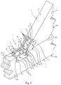
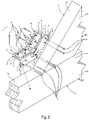
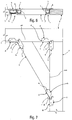
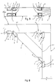
- the present invention is a structural connection 1 comprising a first elongated structural member 50 , a second elongated structural member 50 , a plurality of fasteners 4 , and a connector 5 .
- the connector 5 is a knee-brace stabilizer 5 that makes a structural connection 1 between a first elongated structural member 50 in the form of knee bracing 50 and a second elongated structural member 50 in the form of columns 50 or beams 50 to help stabilize free-standing structures and to comply with many prescriptive deck bracing requirements such as the American Wood Council's "Design for Code Acceptance 6 - Prescriptive Residential Wood Deck Construction Guide".
- the connector 5 preferably braces 2x, 4x and 6x in line post-to-beam configurations.
- the first elongated structural member 50 preferably has a first attachment surface 201 and a second attachment surface 202 angularly related to the first attachment surface 201.
- the second elongated structural member 50 has a third attachment surface 301 and a fourth attachment surface 302 angularly related to the third attachment surface 301.
- the plurality of fasteners 4 preferably are eight-penny (8d) nails; Simpson Strong-Tie Strong -Drive® SD9x1 1/2 (0.131"x1 11.2") screws can be substituted for eight-penny nails.
- the connector 5 is attached with a total of 12 eight-penny nails.
- the first and second substantially planar members 6 and the first and second panel members 9 are formed with fastener openings 16 that provide the optimal fastener arrangement.
- the connector 5 stabilizes the connection 1 between the first elongated structural member 50 and the second elongated structural member 50 in cooperation with the plurality of fasteners 4.
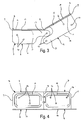
- the connector 5 preferably has first and second substantially planar members 6, a first panel member 9, and a second panel member 9.
- the first and second substantially planar members 6 are formed from a rigid material, preferably galvanized sheet steel.
- the first substantially planar member 6 preferably includes a first end 7
- the second substantially planar member 6 includes a second end 7, and there is a fold region 8 disposed between the first end 7 and the second end 7 whereby the first end 7 and the second end 7 are adapted to be disposed at a selectable angle to one another.
- the first substantially planar member 6 is attached to the first attachment surface 201 of the first elongated structural member 50 by at least one fastener 4 between the first end 7 and the fold region 8 and the second substantially planar member 6 is attached to the third attachment surface 301 of the second elongated structural member 50 by at least one fastener 4 between the second end 7 and the fold region 8.
- the connector 5 is preferably factory-formed with the fold region 8 bent at a 45-degree angle.
- the fold region 8 can be field bent to other angles, with the caveat that it should be field bent only once.
- the first panel member 9 is disposed near the first end 7 of the first substantially planar member 6.
- the first panel member 9 preferably has a first distal end 10 and a first inboard end 11 , the first inboard end 11 adjoining the first substantially planar member 6 at a first angular juncture 12 .
- the second panel member 9 is disposed near the second end 7, the second panel member 9 having a second distal end 10 and a second inboard end 11, the second inboard end 11 adjoining the second substantially planar member 6 at a second angular juncture 12.
- the first panel member 9 and the second panel member 9 are preferably divided from from one another near the fold region 8.
- the first panel member 9 has a first tab extension 13 near the first substantially planar member 6 and the first inboard end 11 and projecting toward the second panel member 9 when the fold region 8 is not folded.
- the first tab extension 13 is preferably attached to one of the second attachment surface 202 and the fourth attachment surface 302 by at least one fastener 4.
- the second panel member 9 has a second tab extension 13 near the second distal end 10 and projecting toward the first panel member 9 when the fold region 8 is not folded, the second tab extension 13 also being attached to one of the second attachment surface 202 and the fourth attachment surface 302 by at least one fastener 4.
- the first tab extension 13 preferably lies between the second tab extension 13 and the substantially planar member 6 when the fold region 8 is not folded.
- the spacial relationships of the constituent parts of the connector 5 of course change as the angle of fold region 8 is changed.
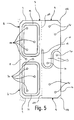
- the first panel member 9 and the second panel member 9 are bounded by a rectangle 100 when the fold region 8 is not folded.
- the flat blank 17 of the entire connector 5 is substantially rectangular, so that material waste is minimized in manufacturing.
- the connector 5 is preferably formed on automated sheet metal forming machinery.
- the width of the first panel member 9 between the first distal end 10 and the first inboard end 11 is preferably the same as the width of the second panel member 9 between the second distal end 10 and the second inboard end 11.
- the first tab extension 13 and the second tab extension 13 are together substantially as wide as the first panel member 9 between the first distal end 10 and the first inboard end 11.
- the first tab extension 13 and the second tab extension 13 preferably are together substantially as wide as the second panel member 9 between the second distal end 10 and the second inboard end 11.
- At least one of the first tab extension 13 and the second tab extension 13 extends past the fold region 8.
- the fold region 8 laterally divides the first and second substantially planar members 6 and one or both of the first and second tab extensions 13 can reach past that division alongside the first and second substantially planar members 6.
- the first panel member 9 and the second panel member 9 are preferably separated by a narrow s-curved gap 15 when the fold region 8 is not folded.
- the first and second panel members 9 draw away from each other but the first and second tab extensions 13 remain in close proximity as one rotates around the end of the other.
- the first panel member 9 is substantially planar and the second panel member 9 is also substantially planar.
- the first panel member 9 is preferably orthogonal to the portion of the first substantially planar member 6 between the first end 7 and the fold region 8.
- the second panel member 9 is also orthogonal to the portion of the second substantially planar member 6 between the second end 7 and the fold region 8.
- the fold region 8 preferably can be folded to any angle between 180 degrees and 90 degrees.
- the substantially planar member 6 of the connector 5 is embossed.
- the substantially planar member 6 of the connector 5 preferably has a first embossment 14 between the first end 7 and the fold region 8, at least one fastener 4 is located within the first embossment 14.
- the substantially planar member 6 of the connector 5 preferably has a second embossment 14 between the second end 7 and the fold region 8, at least one fastener 4 is located within the second embossment 14.
- the embossments 14 are preferably formed as annular rectangles with rounded corners with an un-embossed portion inside each annular rectangle where the fasteners 4 are located.
- the embossments 14 preferably are discrete elements that do not cross the fold region 8.
- one of the first elongated structural member 50 and the second elongated structural member 50 is a vertical post.
- One of the first elongated structural member 50 and the second elongated structural member 50 preferably is a vertical post and the other of the first elongated structural member 50 and the second elongated structural member 50 is a diagonal bracing member.
- one of the first elongated structural member 50 and the second elongated structural member 50 is a vertical post and the other of the first elongated structural member 50 and the second elongated structural member 50 is a horizontal beam.
- At least one of the first panel member 9 and the second panel member 9 is additionally attached to one of the first elongated structural member 50 and the second elongated structural member 50 with a fastener 4 that is not in its corresponding tab extension 13.
- At least one of the first panel member 9 and the second panel member 9 is preferably attached to one of the first elongated structural member 50 and the second elongated structural member 50 with the fastener 4 that is in its corresponding tab extension 13, and the same panel member 9 is attached to the other of the first elongated structural member 50 and the second elongated structural member 50 with the fastener 4 that is not in its corresponding tab extension 13.
- both the first and second tab extensions 13 extend past the fold region 8.
- the first panel member 9 and the second panel member 9 are preferably separated by a narrow gap 15 when the fold region 8 is not folded.
- the first angular juncture 12 does not extend to the fold region 8 such that the narrow gap 15 also separates the first panel member 9 from the first substantially planar member 6 between the fold region 8 and the first end 7 of the substantially planar member 6 adjacent the fold region 8. This effectively separates the first tab extension 13 from the first substantially planar member 6, and not joining the first panel member 9 to the substantially planar member 6 adjacent the fold region 8 substantially increases the strength of the connector 5 because the connector 5 would otherwise be prone to failure by tearing along the first angular juncture 12 adjacent the fold region 8.
- one of the first elongated structural member 50 and the second elongated structural member 50 has an end surface 400 that abuts one of the attachment surfaces 201 or 301 of the other of the first elongated structural member 50 and the second elongated structural member 50.
- the typically connection made with the connector 5 of the present invention is a knee brace where an elongated structural member 2 is disposed at an acute angle to two orthogonally disposed elongated structural members 3 , further strengthening the connection between the orthogonally disposed, elongated structural members 3.
Landscapes
- Engineering & Computer Science (AREA)
- Architecture (AREA)
- General Engineering & Computer Science (AREA)
- Physics & Mathematics (AREA)
- Electromagnetism (AREA)
- Civil Engineering (AREA)
- Structural Engineering (AREA)
- Mechanical Engineering (AREA)
- Joining Of Building Structures In Genera (AREA)
Claims (18)
- Strukturelle Verbindung (1), umfassend:a. ein erstes längliches strukturelles Element (50) mit einer ersten Anbringungsfläche (201) und einer zweiten Anbringungsfläche (202), welche abgewinkelt bezogen auf die erste Anbringungsfläche (201) ist;b. ein zweites längliches strukturelles Element (50) mit einer dritten Anbringungsfläche (301) und einer vierten Anbringungsfläche (302), welche abgewinkelt bezogen auf die dritte Anbringungsfläche (301) ist;d. eine Mehrzahl von Befestigungselementen (4); undc. ein Verbindungselement (5) zum Stabilisieren der Verbindung (1) zwischen dem ersten länglichen strukturellen Element (50) und dem zweiten länglichen strukturellen Element (50) in Zusammenwirkung mit der Mehrzahl von Befestigungselementen (4), wobei das Verbindungselement (5) aufweist:i. erste und zweite im Wesentlichen planare Elemente (6), welche aus einem steifen Material gebildet sind, wobei das erste im Wesentlichen planare Element (6) ein erstes Ende (7) umfasst, wobei das zweite im Wesentlichen planare Element (6) ein zweites Ende (7) umfasst, sowie einen Falzbereich (8), welcher zwischen dem ersten Ende (7) und dem zweiten Ende (7) angeordnet ist, wodurch das erste Ende (7) und das zweite Ende (7) dazu eingerichtet sind, in einem wählbaren Winkel zueinander angeordnet zu sein, wobei das erste im Wesentlichen planare Element (6) an der ersten Anbringungsfläche (201) des ersten länglichen strukturellen Elements (50) durch wenigstens ein Befestigungselement (4) zwischen dem ersten Ende (7) und dem Falzbereich (8) angebracht ist und das zweite im Wesentlichen planare Element (6) an der dritten Anbringungsfläche (301) des zweiten länglichen strukturellen Elements (50) durch wenigstens ein Befestigungselement (4) zwischen dem zweiten Ende (7) und dem Falzbereich (8) angebracht ist;ii. ein erstes Paneelelement (9) nahe dem ersten Ende (7), wobei das erste Paneelelement (9) ein distales Ende (10) und ein erstes inneres Ende (11) aufweist, wobei das erste innere Ende (11) an das erste im Wesentlichen planare Element (6) an einem ersten Winkel-Verbindungselement (12) anliegt; undiii. ein zweites Paneelelement (9) nahe dem zweiten Ende (7), wobei das zweite Paneelelement (9) ein zweites distales Ende (10) und ein zweites inneres Ende (11) aufweist, wobei das zweite innere Ende (11) an das zweite im Wesentlichen planare Element (6) an einem zweiten Winkel-Verbindungselement (12) anliegt;wobei
das erste Paneelelement (9) und das zweite Paneelelement (9) voneinander nahe dem Falzbereich (8) getrennt sind;
dadurch gekennzeichnet, dass
das erste Paneelelement (9) eine erste Streifenverlängerung (13) nahe dem im Wesentlichen planaren Element (6) und dem ersten inneren Ende (11) aufweist und in Richtung des zweiten Paneelelements (9) vorsteht, wenn der Falzbereich (8) nicht gefaltet ist, wobei die erste Streifenverlängerung (13) an eine aus der zweiten Anbringungsfläche (202) und der vierten Anbringungsfläche (302) durch wenigstens ein Befestigungselement (4) angebracht ist; und
das zweite Paneelelement (9) eine zweite Streifenverlängerung (13) nahe dem zweiten distalen Ende (10) aufweist und in Richtung des ersten Paneelelements (9) vorsteht, wenn der Falzbereich (8) nicht gefaltet ist, wobei die zweite Streifenverlängerung (13) an eine aus der zweiten Anbringungsfläche (202) und der vierten Anbringungsfläche (302) durch wenigstens ein Befestigungselement (4) angebracht ist. - Strukturelle Verbindung (1) nach Anspruch 1, wobei:a. die erste Streifenverlängerung (13) zwischen der zweiten Streifenverlängerung (13) und dem im Wesentlichen planaren Element (6) liegt, wenn der Falzbereich (8) nicht gefaltet ist.
- Strukturelle Verbindung (1) nach Anspruch 1 oder Anspruch 2, wobei:a. das erste Paneelelement (9) und das zweite Paneelelement (9) durch ein Rechteck (100) begrenzt sind, wenn der Falzbereich (8) nicht gefaltet ist.
- Strukturelle Verbindung (1) nach einem der vorhergehenden Ansprüche, wobei:a. die Breite des ersten Paneelelements (9) zwischen dem ersten distalen Ende (10) und dem ersten inneren Ende (11) dieselbe ist wie die Breite des zweiten Paneelelements (9) zwischen dem zweiten distalen Ende (10) und dem zweiten inneren Ende (11);b. die erste Streifenverlängerung (13) und die zweite Streifenverlängerung (13) zusammen im Wesentlichen so breit sind wie das erste Paneelelement (9) zwischen dem ersten distalen Ende (10) und dem ersten inneren Ende (11); undc. die erste Streifenverlängerung (13) und die zweite Streifenverlängerung (13) zusammen im Wesentlichen so breit sind wie das zweite Paneelelement (9) zwischen dem zweiten distalen Ende (10) und dem zweiten inneren Ende (11).
- Strukturelle Komponente (1) nach einem der vorhergehenden Ansprüche, wobei:a. wenigstens eine aus der ersten Streifenverlängerung (13) und der zweiten Streifenverlängerung (13) sich über den Falzbereich (8) hinaus erstreckt.
- Strukturelle Verbindung (1) nach einem der vorhergehenden Ansprüche, wobei:a. das erste Paneelelement (9) und das zweite Paneelelement (9) durch einen schmalen S-Kurven-Freiraum (15) getrennt sind, wenn der Falzbereich (8) nicht gefaltet ist.
- Strukturelle Verbindung (1) nach einem der vorhergehenden Ansprüche, wobei:a. das erste Paneelelement (9) im Wesentlichen planar ist; undb. das zweite Paneelelement (9) im Wesentlichen planar ist.
- Strukturelle Verbindung (1) nach einem der vorhergehenden Ansprüche, wobei:a. das erste Paneelelement (9) orthogonal zu dem Abschnitt des im Wesentlichen planaren Elements (6) zwischen dem ersten Ende (7) und dem Falzbereich (8) ist; undb. das zweite Paneelelement (9) orthogonal zu dem Abschnitt des im Wesentlichen planaren Elements (6) zwischen dem zweiten Ende (7) und dem Falzbereich (8) ist.
- Strukturelle Verbindung (1) nach einem der vorhergehenden Ansprüche, wobei:a. der Falzbereich (8) auf jeden Winkel zwischen 180 Grad und 90 Grad gefaltet werden kann.
- Strukturelle Verbindung (1) nach einem der vorhergehenden Ansprüche, wobei:a. eines aus dem ersten länglichen strukturellen Element (50) und dem zweiten länglichen strukturellen Element (50) ein vertikaler Pfahl ist.
- Strukturelle Verbindung (1) nach einem der vorhergehenden Ansprüche, wobei:a. das erste und zweite im Wesentlichen planare Element (6) des Verbindungselements (5) geprägt sind.
- Strukturelle Verbindung (1) nach einem der vorhergehenden Ansprüche, wobei:a. das erste im Wesentlichen planare Element (6) des Verbindungselements (5) eine erste diskrete Prägung (14) zwischen dem ersten Ende (7) und dem Falzbereich (8) aufweist; undb. das zweite im Wesentlichen planare Element (6) des Verbindungselements (5) eine zweite diskrete Prägung (14) zwischen dem zweiten Ende (7) und dem Falzbereich (8) aufweist.
- Strukturelle Verbindung (1) nach einem der vorhergehenden Ansprüche, wobei:a. eines aus dem ersten länglichen strukturellen Element (50) und dem zweiten länglichen strukturellen Element (50) ein vertikaler Pfahl ist; undb. das andere aus dem ersten länglichen strukturellen Element (50) und dem zweiten länglichen strukturellen Element (50) ein diagonales Versteifungselement ist.
- Strukturelle Verbindung (1) nach einem der Ansprüche 1 bis 12, wobei:a. eines aus dem ersten länglichen strukturellen Element (50) und dem zweiten länglichen strukturellen Element (50) ein vertikaler Pfahl ist; undb. das andere aus dem ersten länglichen strukturellen Element (50) und dem zweiten länglichen strukturellen Element (50) ein horizontaler Balken ist.
- Strukturelle Verbindung (1) nach einem der vorhergehenden Ansprüche, wobei:a. wenigstens eines aus dem ersten Paneelelement (9) und dem zweiten Paneelelement (9) zusätzlich an einem aus dem ersten länglichen strukturellen Element (50) und dem zweiten länglichen strukturellen Element (50) mit einem Befestigungselement (4) angebracht ist, welches sich nicht in seiner entsprechenden Streifenverlängerung (13) befindet.
- Strukturelle Verbindung (1) nach einem der vorhergehenden Ansprüche, wobei:a. wenigstens eines aus dem ersten Paneelelement (9) und dem zweiten Paneelelement (9) an einem aus dem ersten länglichen strukturellen Element (50) und dem zweiten länglichen strukturellen Element (50) mit dem Befestigungselement (4) angebracht ist, welches sich in seiner entsprechenden Streifenverlängerung (13) befindet, und das selbe Paneelelement (9) an dem anderen aus dem ersten länglichen strukturellen Element (50) und dem zweiten länglichen strukturellen Element (50) mit dem Befestigungselement (4) angebracht ist, welches sich nicht in seiner entsprechenden Streifenverlängerung (13) befindet.
- Strukturelle Verbindung (1) nach einem der vorhergehenden Ansprüche, wobei:a. sich die erste Streifenverlängerung (13) über den Falzbereich (8) hinaus erstreckt;b. das erste Paneelelement (9) und das zweite Paneelelement (9) durch einen schmalen Freiraum (15) getrennt sind, wenn der Falzbereich (8) nicht gefaltet ist; undb. sich das erste Winkel-Verbindungselement (12) nicht bis zu dem Falzbereich (8) erstreckt, so dass der schmale Freiraum (15) ebenfalls das erste Paneelelement (9) von dem ersten im Wesentlichen planaren Element (6) entlang einem Abschnitt des ersten im Wesentlichen planaren Elements (6) zwischen dem Falzbereich (8) und dem ersten Ende (7) des ersten im Wesentlichen planaren Elements (6) benachbart zu dem Falzbereich (8) trennt.
- Strukturelle Verbindung (1) nach einem der vorhergehenden Ansprüche, wobei:a. eines aus dem ersten länglichen strukturellen Element (50) und dem zweiten länglichen strukturellen Element (50) eine Endfläche (400) aufweist, welche gegen eine der Anbringungsflächen (201, 202, 301, 302) des anderen aus dem ersten länglichen strukturellen Element (50) und dem zweiten länglichen strukturellen Element (50) anliegt.
Applications Claiming Priority (1)
| Application Number | Priority Date | Filing Date | Title |
|---|---|---|---|
| US14/225,265 US9045895B1 (en) | 2014-03-25 | 2014-03-25 | Knee brace |
Publications (2)
| Publication Number | Publication Date |
|---|---|
| EP2924185A1 EP2924185A1 (de) | 2015-09-30 |
| EP2924185B1 true EP2924185B1 (de) | 2018-03-07 |
Family
ID=53054856
Family Applications (1)
| Application Number | Title | Priority Date | Filing Date |
|---|---|---|---|
| EP15160706.6A Not-in-force EP2924185B1 (de) | 2014-03-25 | 2015-03-25 | Knieschiene |
Country Status (5)
| Country | Link |
|---|---|
| US (1) | US9045895B1 (de) |
| EP (1) | EP2924185B1 (de) |
| JP (1) | JP2015183513A (de) |
| AU (1) | AU2015201535A1 (de) |
| CA (1) | CA2886169C (de) |
Families Citing this family (7)
| Publication number | Priority date | Publication date | Assignee | Title |
|---|---|---|---|---|
| DE102014222107B4 (de) * | 2014-07-23 | 2021-03-25 | Adient Luxembourg Holding S.À R.L. | Verbindungselement, Profilsystem und Verfahren zur Herstellung eines solchen Profilsystems |
| DE102015007267A1 (de) * | 2015-06-10 | 2016-12-15 | Gebr. Schmidt GbR (vertretungsber. Gesellschafter: Andreas Schmidt, 33649 Bielefeld | Verbindungselement für Wandbauelemente |
| US9809974B1 (en) * | 2016-07-20 | 2017-11-07 | Columbia Insurance Company | Adjustable deck tension tie |
| US11131088B2 (en) * | 2018-01-26 | 2021-09-28 | Simpson Strong-Tie Company Inc. | Hinged connector |
| WO2020150281A1 (en) * | 2019-01-14 | 2020-07-23 | Simpson Strong-Tie Company Inc. | Reinforced hinge connector |
| US11118349B2 (en) | 2020-01-29 | 2021-09-14 | Laura Montoya | Rafter reinforcement bracket apparatus |
| US11512485B2 (en) * | 2020-07-02 | 2022-11-29 | Thomas B. Coates, JR. | Column bracket assembly and related methods and structures |
Family Cites Families (84)
| Publication number | Priority date | Publication date | Assignee | Title |
|---|---|---|---|---|
| US230438A (en) | 1880-07-27 | poeter | ||
| US493882A (en) | 1893-03-21 | Corner-brace | ||
| US1161432A (en) | 1914-11-09 | 1915-11-23 | Aaron Wolf | Corner-post fastening. |
| US1471159A (en) | 1922-05-16 | 1923-10-16 | Howie Thomas | Joint member for screen frames and the like |
| US1607166A (en) | 1925-08-03 | 1926-11-16 | Mccall Benjamin Bartley | Building construction |
| US1945925A (en) * | 1932-11-08 | 1934-02-06 | Stiefel William | Metallic tie structure |
| US2037736A (en) | 1934-12-14 | 1936-04-21 | Crane Packing Co | Jointed structure |
| US2141107A (en) | 1937-12-29 | 1938-12-20 | Gerald G Greulich | Splice for steel bearing piles |
| US2203987A (en) | 1938-12-07 | 1940-06-11 | Galante Ermanno | Corner piece for frames |
| US2268681A (en) | 1940-01-17 | 1942-01-06 | William F Vernon | Advertising door brace |
| US2473217A (en) | 1946-09-06 | 1949-06-14 | Peoples Company | Rod clamp or the like |
| US2590159A (en) | 1947-04-05 | 1952-03-25 | William E Davis | Corner fitting for knockdown structures |
| US2638643A (en) | 1949-06-02 | 1953-05-19 | Kenneth T Snow | Building bracket |
| US2661822A (en) | 1950-06-10 | 1953-12-08 | Wisco Inc | Door corner |
| US2867302A (en) | 1956-10-11 | 1959-01-06 | Verner M Miller | Connecting clip |
| US3062570A (en) | 1959-11-04 | 1962-11-06 | Schwartz Metal Company Inc | Connector |
| US3102616A (en) | 1961-08-31 | 1963-09-03 | Tiffany Stand Company | Support construction |
| US3184800A (en) | 1961-10-23 | 1965-05-25 | Lynn H Ewing | Rafter support |
| US3305252A (en) | 1962-11-21 | 1967-02-21 | Automated Building Components | Corner connector |
| US3365222A (en) | 1965-04-19 | 1968-01-23 | Polyak Jack | Wall brace |
| US3423898A (en) | 1966-07-28 | 1969-01-28 | Intern Enterprises Inc | Roof framing system |
| JPS4832320A (de) * | 1971-08-28 | 1973-04-28 | ||
| US3914062A (en) | 1974-07-30 | 1975-10-21 | Gem Industries | Welded corner construction |
| US3912407A (en) | 1974-07-30 | 1975-10-14 | Gem Industries | Corner connector |
| US4036149A (en) | 1975-08-04 | 1977-07-19 | Miner Enterprises, Inc. | Fabricated hopper car outlet door frame |
| US4120600A (en) | 1976-04-12 | 1978-10-17 | Rees Gordon H | Corner bracket |
| US4039137A (en) | 1976-05-11 | 1977-08-02 | Smith Edward J | Bend or break shelf support |
| US4022537A (en) | 1976-07-12 | 1977-05-10 | Simpson Manufacturing Co., Inc. | Knee brace for glulam and heavy timber construction |
| US4148164A (en) * | 1977-10-17 | 1979-04-10 | Humphrey Gerald A | Fascia board support |
| US4202649A (en) | 1978-12-04 | 1980-05-13 | Efficiency Production, Inc. | Front plate for trench boxes |
| US4344366A (en) | 1979-11-28 | 1982-08-17 | The Youngstown Steel Door Company | Railway car door driver |
| DE3115355A1 (de) | 1981-04-16 | 1982-11-18 | Artur Dr.H.C. 7244 Waldachtal Fischer | Zusammensteckbarer, als fruehbeet zu verwendender kastenfoermiger behaelter |
| US4514950A (en) | 1981-11-27 | 1985-05-07 | Goodson Jr Albert A | Building framing system and method |
| JPS5913503U (ja) * | 1982-07-19 | 1984-01-27 | 根本 繁雄 | 通気リブつき接合部材 |
| JPS5954602U (ja) * | 1982-10-04 | 1984-04-10 | 根本 繁雄 | 建築用接合具 |
| US4513554A (en) | 1982-12-27 | 1985-04-30 | Lawrence Brothers, Inc. | Barn door framing system |
| US4480941A (en) | 1983-03-04 | 1984-11-06 | Simpson Strong-Tie Company, Inc. | Double shear angled fastener connector |
| US4688358A (en) | 1983-05-23 | 1987-08-25 | Madray Herbert R | Construction system |
| US4592672A (en) | 1984-03-07 | 1986-06-03 | Ruch Jr Asher G | Structural joint apparatus |
| US4572695A (en) | 1984-08-20 | 1986-02-25 | Simpson Strong-Tie Company, Inc. | Six finger wood jointing connector |
| US4699547A (en) | 1985-03-15 | 1987-10-13 | Seegmiller Ben L | Mine truss structures and method |
| US4637195A (en) | 1985-12-16 | 1987-01-20 | Davis Roy E | Reinforcing member for wooden structure |
| US4683698A (en) | 1986-07-11 | 1987-08-04 | Butler Manufacturing Company | Load transfer clip for roof panel support trusses |
| US4812075A (en) | 1986-12-04 | 1989-03-14 | Lavin Sr Gerald P | Inside corner bracket |
| US4805315A (en) | 1988-02-29 | 1989-02-21 | Nesbitt Hugh M | Free standing squaring tool with open corners |
| FI82120C (fi) | 1988-09-21 | 1991-01-10 | Mauri Maekinen | Hoernfogstycke. |
| US5217317A (en) | 1989-06-23 | 1993-06-08 | United Steel Products Company | Bracket with angled nailing feature |
| AU6222390A (en) | 1989-09-06 | 1991-03-21 | Arthur Raymond Turner | Connectors for timber building components |
| AU6222290A (en) | 1989-09-06 | 1991-03-14 | Arthur Raymond Turner | Developments in building |
| US4957186A (en) | 1989-12-11 | 1990-09-18 | T J International, Inc. | Span-adjustable open-web support bracket |
| US5010709A (en) * | 1990-02-28 | 1991-04-30 | Felix Paz | Bendable channel construction element |
| US5312078A (en) | 1991-06-05 | 1994-05-17 | Tenn-Tex, Inc. | Cabinet corner brace |
| US5104252A (en) | 1991-10-31 | 1992-04-14 | Simpson Strong-Tie Company, Inc. | Hanger connection |
| US5335469A (en) * | 1992-10-13 | 1994-08-09 | Simpson Strong-Tie Company, Inc. | Rafter to plate connection |
| USD364331S (en) | 1993-08-18 | 1995-11-21 | Simpson Strong-Tie Company, Inc. | Structural connector |
| US5380115A (en) * | 1993-10-14 | 1995-01-10 | Simpson Strong-Tie Co., Inc. | Hip corner plate connection |
| US5380116A (en) * | 1993-10-14 | 1995-01-10 | Simpson Strong-Tie Company, Inc. | Hip ridge connection |
| US5603580A (en) | 1995-05-30 | 1997-02-18 | Simpson Strong-Tie Company, Inc. | Positive angle fastener device |
| US5639150A (en) | 1995-09-22 | 1997-06-17 | Amco Engineering Co. | Electronic component enclosure and method |
| USD374165S (en) | 1995-11-07 | 1996-10-01 | Thomas O. Marshall | Deck seat mounting bracket |
| US5806265A (en) | 1996-01-25 | 1998-09-15 | Sluiter; Scott E. | Metal truss joining gusset |
| US5797694A (en) | 1996-03-29 | 1998-08-25 | Alpine Engineered Products, Inc. | Adjustable ridge connector |
| US5827947A (en) | 1997-01-17 | 1998-10-27 | Advanced Technology Materials, Inc. | Piezoelectric sensor for hydride gases, and fluid monitoring apparatus comprising same |
| USD406813S (en) | 1997-04-24 | 1999-03-16 | Thomas & Betts International, Inc. | Electrical ground connector for meter panel |
| US6408482B1 (en) | 1997-09-09 | 2002-06-25 | Kimball International, Inc. | Standardized furniture unit and bracket therefor |
| USD429001S (en) | 1997-11-19 | 2000-08-01 | Robert Bosch Gmbh | Frame profile |
| CA2231483A1 (en) | 1998-03-06 | 1999-09-06 | Mga Construction Hardware & Steel Fabricating Ltd. | Joist bracing apparatus |
| USD427894S (en) | 1998-09-07 | 2000-07-11 | Robert Bosch Gmbh | Fastening angle |
| US6230467B1 (en) * | 1999-02-18 | 2001-05-15 | Simpson Strong-Tie Co., Inc. | Steel joist hanger |
| US6260402B1 (en) | 1999-03-10 | 2001-07-17 | Simpson Strong-Tie Company, Inc. | Method for forming a short-radius bend in flanged sheet metal member |
| US6397552B1 (en) | 1999-07-23 | 2002-06-04 | Michael Bourque | Deck attachment bracket and method of attaching a deck to a building |
| USD430006S (en) | 1999-12-20 | 2000-08-29 | Finger Jr Paul Alton | Connector for sign panels |
| US6772570B2 (en) | 2000-10-18 | 2004-08-10 | Edward Horne | Variable pitch connector brackets for use in attaching supporting members to bearing members in roofs |
| US20020112439A1 (en) | 2001-02-16 | 2002-08-22 | Rosas Ted A. | Framing fastener for connecting construction support members |
| US20020124483A1 (en) | 2001-03-09 | 2002-09-12 | Rosas Ted A. | Framing fastener for connecting construction support members |
| JP2003129568A (ja) * | 2001-10-19 | 2003-05-08 | Ishida Komuten:Kk | 木造建物の火打ち構造および方杖構造ならびに内法構造 |
| US20030154685A1 (en) | 2002-02-20 | 2003-08-21 | Williams Troy D. | Truss joint reinforcement plate |
| US7788873B2 (en) * | 2002-10-26 | 2010-09-07 | Simpson Strong-Tie Co., I{umlaut over (n)}c. | Gable end brace |
| US7293390B2 (en) * | 2003-10-23 | 2007-11-13 | Simpson Strong-Tie Co., Inc. | Roof boundary clip |
| EP1692404A4 (de) | 2003-11-26 | 2008-04-09 | Carinya Mfg Co Pty Ltd | Verbesserungen bei der bildung von halterungsstreifen |
| US7631463B2 (en) | 2006-08-21 | 2009-12-15 | United Steel Products Company | Stair hanger |
| US7805894B2 (en) * | 2006-12-08 | 2010-10-05 | Andrew Contasti | Construction connectors incorporating hardware |
| US8443569B2 (en) * | 2009-11-06 | 2013-05-21 | Simpson Strong-Tie Company, Inc. | Four-way radial connector |
| US8528268B1 (en) | 2010-12-02 | 2013-09-10 | Component Manufacturing Company | Trilateral bracing structure for reinforcing a building frame structure |
-
2014
- 2014-03-25 US US14/225,265 patent/US9045895B1/en active Active
-
2015
- 2015-03-24 JP JP2015060471A patent/JP2015183513A/ja not_active Ceased
- 2015-03-24 CA CA2886169A patent/CA2886169C/en active Active
- 2015-03-25 AU AU2015201535A patent/AU2015201535A1/en not_active Abandoned
- 2015-03-25 EP EP15160706.6A patent/EP2924185B1/de not_active Not-in-force
Non-Patent Citations (1)
| Title |
|---|
| None * |
Also Published As
| Publication number | Publication date |
|---|---|
| EP2924185A1 (de) | 2015-09-30 |
| CA2886169C (en) | 2022-03-08 |
| AU2015201535A1 (en) | 2015-10-15 |
| JP2015183513A (ja) | 2015-10-22 |
| US9045895B1 (en) | 2015-06-02 |
| CA2886169A1 (en) | 2015-09-25 |
Similar Documents
| Publication | Publication Date | Title |
|---|---|---|
| EP2924185B1 (de) | Knieschiene | |
| JP6427163B2 (ja) | 涙滴状切込み及びオフセットした切込み付きブリッジコネクタ | |
| US5004369A (en) | Slope and skew hanger | |
| AU2013205474B2 (en) | A Hanger Bracket | |
| EP0913535B1 (de) | Starrer Innenverbinder | |
| US5217317A (en) | Bracket with angled nailing feature | |
| US8484927B2 (en) | Right-angle girder tie | |
| EP3318684A1 (de) | Verborgener unterzugbinder mit abgeschrägtem mittelflansch | |
| US20080209845A1 (en) | Quadruple mono truss connection | |
| US20050284060A1 (en) | Rigid foam building panel | |
| EP1760212A2 (de) | Abgeschrägte Fachwerkträgerbefestigung | |
| KR102414815B1 (ko) | 외장재의 부착구 및 건물의 외장 구조 | |
| EP2924186B1 (de) | Verbinding für gebäude mit nagelplattenhängevorrichtung mit biegbarer lasche | |
| USH1795H (en) | Gusset angle corner connection | |
| CN108019008B (zh) | 柱板插扣式安装结构及其安装方法 | |
| NZ706317A (en) | Knee brace | |
| US5275449A (en) | Elongated member for joining ducts | |
| JP6393539B2 (ja) | 壁面取付用ベース部材、壁面取付用ベースパネルおよび壁面取付システム | |
| KR100271081B1 (ko) | 선반 유니트용 골조(framework for shelving unit) | |
| EP2500487B2 (de) | Dachfenster mit Eckmontagewinkel | |
| KR101308647B1 (ko) | 가구용 프레임 다리구조 | |
| JP2019105030A (ja) | 野縁接続金物 | |
| JP7340435B2 (ja) | 鋼管柱の継手構造 | |
| CN212536335U (zh) | 一种高强度连接件 | |
| JP3088396U (ja) | 引寄せ金物 |
Legal Events
| Date | Code | Title | Description |
|---|---|---|---|
| PUAI | Public reference made under article 153(3) epc to a published international application that has entered the european phase |
Free format text: ORIGINAL CODE: 0009012 |
|
| AK | Designated contracting states |
Kind code of ref document: A1 Designated state(s): AL AT BE BG CH CY CZ DE DK EE ES FI FR GB GR HR HU IE IS IT LI LT LU LV MC MK MT NL NO PL PT RO RS SE SI SK SM TR |
|
| AX | Request for extension of the european patent |
Extension state: BA ME |
|
| 17P | Request for examination filed |
Effective date: 20160329 |
|
| RBV | Designated contracting states (corrected) |
Designated state(s): AL AT BE BG CH CY CZ DE DK EE ES FI FR GB GR HR HU IE IS IT LI LT LU LV MC MK MT NL NO PL PT RO RS SE SI SK SM TR |
|
| GRAP | Despatch of communication of intention to grant a patent |
Free format text: ORIGINAL CODE: EPIDOSNIGR1 |
|
| RIC1 | Information provided on ipc code assigned before grant |
Ipc: E04B 1/24 20060101ALN20160811BHEP Ipc: E04B 1/26 20060101AFI20160811BHEP |
|
| INTG | Intention to grant announced |
Effective date: 20160831 |
|
| GRAJ | Information related to disapproval of communication of intention to grant by the applicant or resumption of examination proceedings by the epo deleted |
Free format text: ORIGINAL CODE: EPIDOSDIGR1 |
|
| GRAP | Despatch of communication of intention to grant a patent |
Free format text: ORIGINAL CODE: EPIDOSNIGR1 |
|
| INTC | Intention to grant announced (deleted) | ||
| INTG | Intention to grant announced |
Effective date: 20170529 |
|
| RIC1 | Information provided on ipc code assigned before grant |
Ipc: E04B 1/26 20060101AFI20170512BHEP Ipc: E04B 1/24 20060101ALN20170512BHEP |
|
| GRAS | Grant fee paid |
Free format text: ORIGINAL CODE: EPIDOSNIGR3 |
|
| GRAA | (expected) grant |
Free format text: ORIGINAL CODE: 0009210 |
|
| AK | Designated contracting states |
Kind code of ref document: B1 Designated state(s): AL AT BE BG CH CY CZ DE DK EE ES FI FR GB GR HR HU IE IS IT LI LT LU LV MC MK MT NL NO PL PT RO RS SE SI SK SM TR |
|
| REG | Reference to a national code |
Ref country code: GB Ref legal event code: FG4D |
|
| RIN1 | Information on inventor provided before grant (corrected) |
Inventor name: LIN, JIN-JIE Inventor name: STAUFFER, TIMOTHY M. |
|
| REG | Reference to a national code |
Ref country code: CH Ref legal event code: EP Ref country code: AT Ref legal event code: REF Ref document number: 976713 Country of ref document: AT Kind code of ref document: T Effective date: 20180315 |
|
| REG | Reference to a national code |
Ref country code: IE Ref legal event code: FG4D |
|
| REG | Reference to a national code |
Ref country code: DE Ref legal event code: R096 Ref document number: 602015008515 Country of ref document: DE |
|
| REG | Reference to a national code |
Ref country code: NL Ref legal event code: MP Effective date: 20180307 |
|
| REG | Reference to a national code |
Ref country code: LT Ref legal event code: MG4D |
|
| PG25 | Lapsed in a contracting state [announced via postgrant information from national office to epo] |
Ref country code: NO Free format text: LAPSE BECAUSE OF FAILURE TO SUBMIT A TRANSLATION OF THE DESCRIPTION OR TO PAY THE FEE WITHIN THE PRESCRIBED TIME-LIMIT Effective date: 20180607 Ref country code: FI Free format text: LAPSE BECAUSE OF FAILURE TO SUBMIT A TRANSLATION OF THE DESCRIPTION OR TO PAY THE FEE WITHIN THE PRESCRIBED TIME-LIMIT Effective date: 20180307 Ref country code: HR Free format text: LAPSE BECAUSE OF FAILURE TO SUBMIT A TRANSLATION OF THE DESCRIPTION OR TO PAY THE FEE WITHIN THE PRESCRIBED TIME-LIMIT Effective date: 20180307 Ref country code: CY Free format text: LAPSE BECAUSE OF FAILURE TO SUBMIT A TRANSLATION OF THE DESCRIPTION OR TO PAY THE FEE WITHIN THE PRESCRIBED TIME-LIMIT Effective date: 20180307 Ref country code: LT Free format text: LAPSE BECAUSE OF FAILURE TO SUBMIT A TRANSLATION OF THE DESCRIPTION OR TO PAY THE FEE WITHIN THE PRESCRIBED TIME-LIMIT Effective date: 20180307 Ref country code: ES Free format text: LAPSE BECAUSE OF FAILURE TO SUBMIT A TRANSLATION OF THE DESCRIPTION OR TO PAY THE FEE WITHIN THE PRESCRIBED TIME-LIMIT Effective date: 20180307 |
|
| REG | Reference to a national code |
Ref country code: AT Ref legal event code: MK05 Ref document number: 976713 Country of ref document: AT Kind code of ref document: T Effective date: 20180307 |
|
| PG25 | Lapsed in a contracting state [announced via postgrant information from national office to epo] |
Ref country code: BG Free format text: LAPSE BECAUSE OF FAILURE TO SUBMIT A TRANSLATION OF THE DESCRIPTION OR TO PAY THE FEE WITHIN THE PRESCRIBED TIME-LIMIT Effective date: 20180607 Ref country code: GR Free format text: LAPSE BECAUSE OF FAILURE TO SUBMIT A TRANSLATION OF THE DESCRIPTION OR TO PAY THE FEE WITHIN THE PRESCRIBED TIME-LIMIT Effective date: 20180608 Ref country code: LV Free format text: LAPSE BECAUSE OF FAILURE TO SUBMIT A TRANSLATION OF THE DESCRIPTION OR TO PAY THE FEE WITHIN THE PRESCRIBED TIME-LIMIT Effective date: 20180307 Ref country code: SE Free format text: LAPSE BECAUSE OF FAILURE TO SUBMIT A TRANSLATION OF THE DESCRIPTION OR TO PAY THE FEE WITHIN THE PRESCRIBED TIME-LIMIT Effective date: 20180307 Ref country code: RS Free format text: LAPSE BECAUSE OF FAILURE TO SUBMIT A TRANSLATION OF THE DESCRIPTION OR TO PAY THE FEE WITHIN THE PRESCRIBED TIME-LIMIT Effective date: 20180307 |
|
| REG | Reference to a national code |
Ref country code: DE Ref legal event code: R119 Ref document number: 602015008515 Country of ref document: DE |
|
| PG25 | Lapsed in a contracting state [announced via postgrant information from national office to epo] |
Ref country code: NL Free format text: LAPSE BECAUSE OF FAILURE TO SUBMIT A TRANSLATION OF THE DESCRIPTION OR TO PAY THE FEE WITHIN THE PRESCRIBED TIME-LIMIT Effective date: 20180307 Ref country code: RO Free format text: LAPSE BECAUSE OF FAILURE TO SUBMIT A TRANSLATION OF THE DESCRIPTION OR TO PAY THE FEE WITHIN THE PRESCRIBED TIME-LIMIT Effective date: 20180307 Ref country code: EE Free format text: LAPSE BECAUSE OF FAILURE TO SUBMIT A TRANSLATION OF THE DESCRIPTION OR TO PAY THE FEE WITHIN THE PRESCRIBED TIME-LIMIT Effective date: 20180307 Ref country code: IT Free format text: LAPSE BECAUSE OF FAILURE TO SUBMIT A TRANSLATION OF THE DESCRIPTION OR TO PAY THE FEE WITHIN THE PRESCRIBED TIME-LIMIT Effective date: 20180307 Ref country code: AL Free format text: LAPSE BECAUSE OF FAILURE TO SUBMIT A TRANSLATION OF THE DESCRIPTION OR TO PAY THE FEE WITHIN THE PRESCRIBED TIME-LIMIT Effective date: 20180307 Ref country code: PL Free format text: LAPSE BECAUSE OF FAILURE TO SUBMIT A TRANSLATION OF THE DESCRIPTION OR TO PAY THE FEE WITHIN THE PRESCRIBED TIME-LIMIT Effective date: 20180307 |
|
| REG | Reference to a national code |
Ref country code: CH Ref legal event code: PL |
|
| PG25 | Lapsed in a contracting state [announced via postgrant information from national office to epo] |
Ref country code: SK Free format text: LAPSE BECAUSE OF FAILURE TO SUBMIT A TRANSLATION OF THE DESCRIPTION OR TO PAY THE FEE WITHIN THE PRESCRIBED TIME-LIMIT Effective date: 20180307 Ref country code: CZ Free format text: LAPSE BECAUSE OF FAILURE TO SUBMIT A TRANSLATION OF THE DESCRIPTION OR TO PAY THE FEE WITHIN THE PRESCRIBED TIME-LIMIT Effective date: 20180307 Ref country code: AT Free format text: LAPSE BECAUSE OF FAILURE TO SUBMIT A TRANSLATION OF THE DESCRIPTION OR TO PAY THE FEE WITHIN THE PRESCRIBED TIME-LIMIT Effective date: 20180307 Ref country code: SM Free format text: LAPSE BECAUSE OF FAILURE TO SUBMIT A TRANSLATION OF THE DESCRIPTION OR TO PAY THE FEE WITHIN THE PRESCRIBED TIME-LIMIT Effective date: 20180307 |
|
| REG | Reference to a national code |
Ref country code: BE Ref legal event code: MM Effective date: 20180331 |
|
| REG | Reference to a national code |
Ref country code: IE Ref legal event code: MM4A |
|
| PG25 | Lapsed in a contracting state [announced via postgrant information from national office to epo] |
Ref country code: PT Free format text: LAPSE BECAUSE OF FAILURE TO SUBMIT A TRANSLATION OF THE DESCRIPTION OR TO PAY THE FEE WITHIN THE PRESCRIBED TIME-LIMIT Effective date: 20180709 Ref country code: LU Free format text: LAPSE BECAUSE OF NON-PAYMENT OF DUE FEES Effective date: 20180325 |
|
| PLBE | No opposition filed within time limit |
Free format text: ORIGINAL CODE: 0009261 |
|
| STAA | Information on the status of an ep patent application or granted ep patent |
Free format text: STATUS: NO OPPOSITION FILED WITHIN TIME LIMIT |
|
| PG25 | Lapsed in a contracting state [announced via postgrant information from national office to epo] |
Ref country code: DK Free format text: LAPSE BECAUSE OF FAILURE TO SUBMIT A TRANSLATION OF THE DESCRIPTION OR TO PAY THE FEE WITHIN THE PRESCRIBED TIME-LIMIT Effective date: 20180307 Ref country code: DE Free format text: LAPSE BECAUSE OF NON-PAYMENT OF DUE FEES Effective date: 20181002 Ref country code: IE Free format text: LAPSE BECAUSE OF NON-PAYMENT OF DUE FEES Effective date: 20180325 Ref country code: MC Free format text: LAPSE BECAUSE OF FAILURE TO SUBMIT A TRANSLATION OF THE DESCRIPTION OR TO PAY THE FEE WITHIN THE PRESCRIBED TIME-LIMIT Effective date: 20180307 |
|
| 26N | No opposition filed |
Effective date: 20181210 |
|
| PG25 | Lapsed in a contracting state [announced via postgrant information from national office to epo] |
Ref country code: CH Free format text: LAPSE BECAUSE OF NON-PAYMENT OF DUE FEES Effective date: 20180331 Ref country code: SI Free format text: LAPSE BECAUSE OF FAILURE TO SUBMIT A TRANSLATION OF THE DESCRIPTION OR TO PAY THE FEE WITHIN THE PRESCRIBED TIME-LIMIT Effective date: 20180307 Ref country code: LI Free format text: LAPSE BECAUSE OF NON-PAYMENT OF DUE FEES Effective date: 20180331 Ref country code: BE Free format text: LAPSE BECAUSE OF NON-PAYMENT OF DUE FEES Effective date: 20180331 |
|
| PG25 | Lapsed in a contracting state [announced via postgrant information from national office to epo] |
Ref country code: FR Free format text: LAPSE BECAUSE OF NON-PAYMENT OF DUE FEES Effective date: 20180507 |
|
| GBPC | Gb: european patent ceased through non-payment of renewal fee |
Effective date: 20190325 |
|
| PG25 | Lapsed in a contracting state [announced via postgrant information from national office to epo] |
Ref country code: MT Free format text: LAPSE BECAUSE OF NON-PAYMENT OF DUE FEES Effective date: 20180325 Ref country code: GB Free format text: LAPSE BECAUSE OF NON-PAYMENT OF DUE FEES Effective date: 20190325 |
|
| PG25 | Lapsed in a contracting state [announced via postgrant information from national office to epo] |
Ref country code: TR Free format text: LAPSE BECAUSE OF FAILURE TO SUBMIT A TRANSLATION OF THE DESCRIPTION OR TO PAY THE FEE WITHIN THE PRESCRIBED TIME-LIMIT Effective date: 20180307 |
|
| PG25 | Lapsed in a contracting state [announced via postgrant information from national office to epo] |
Ref country code: MK Free format text: LAPSE BECAUSE OF NON-PAYMENT OF DUE FEES Effective date: 20180307 Ref country code: HU Free format text: LAPSE BECAUSE OF FAILURE TO SUBMIT A TRANSLATION OF THE DESCRIPTION OR TO PAY THE FEE WITHIN THE PRESCRIBED TIME-LIMIT; INVALID AB INITIO Effective date: 20150325 |
|
| PG25 | Lapsed in a contracting state [announced via postgrant information from national office to epo] |
Ref country code: IS Free format text: LAPSE BECAUSE OF FAILURE TO SUBMIT A TRANSLATION OF THE DESCRIPTION OR TO PAY THE FEE WITHIN THE PRESCRIBED TIME-LIMIT Effective date: 20180707 |