EP2923788B1 - Plaquette de coupe pour fraisage - Google Patents
Plaquette de coupe pour fraisage Download PDFInfo
- Publication number
- EP2923788B1 EP2923788B1 EP13857233.4A EP13857233A EP2923788B1 EP 2923788 B1 EP2923788 B1 EP 2923788B1 EP 13857233 A EP13857233 A EP 13857233A EP 2923788 B1 EP2923788 B1 EP 2923788B1
- Authority
- EP
- European Patent Office
- Prior art keywords
- cutting edge
- cutting
- minor
- flat
- major
- Prior art date
- Legal status (The legal status is an assumption and is not a legal conclusion. Google has not performed a legal analysis and makes no representation as to the accuracy of the status listed.)
- Active
Links
- 238000003801 milling Methods 0.000 title claims description 17
- 230000003746 surface roughness Effects 0.000 claims description 15
- 230000015572 biosynthetic process Effects 0.000 description 5
- 230000000052 comparative effect Effects 0.000 description 2
- 230000000694 effects Effects 0.000 description 2
- 239000011195 cermet Substances 0.000 description 1
- 238000005516 engineering process Methods 0.000 description 1
- 238000000227 grinding Methods 0.000 description 1
- 239000000463 material Substances 0.000 description 1
- 238000005259 measurement Methods 0.000 description 1
- 238000000034 method Methods 0.000 description 1
- 238000005245 sintering Methods 0.000 description 1
Images
Classifications
-
- B—PERFORMING OPERATIONS; TRANSPORTING
- B23—MACHINE TOOLS; METAL-WORKING NOT OTHERWISE PROVIDED FOR
- B23C—MILLING
- B23C5/00—Milling-cutters
- B23C5/02—Milling-cutters characterised by the shape of the cutter
- B23C5/06—Face-milling cutters, i.e. having only or primarily a substantially flat cutting surface
-
- B—PERFORMING OPERATIONS; TRANSPORTING
- B23—MACHINE TOOLS; METAL-WORKING NOT OTHERWISE PROVIDED FOR
- B23C—MILLING
- B23C5/00—Milling-cutters
- B23C5/16—Milling-cutters characterised by physical features other than shape
- B23C5/20—Milling-cutters characterised by physical features other than shape with removable cutter bits or teeth or cutting inserts
- B23C5/202—Plate-like cutting inserts with special form
-
- B—PERFORMING OPERATIONS; TRANSPORTING
- B23—MACHINE TOOLS; METAL-WORKING NOT OTHERWISE PROVIDED FOR
- B23C—MILLING
- B23C2200/00—Details of milling cutting inserts
- B23C2200/04—Overall shape
- B23C2200/0455—Square
-
- B—PERFORMING OPERATIONS; TRANSPORTING
- B23—MACHINE TOOLS; METAL-WORKING NOT OTHERWISE PROVIDED FOR
- B23C—MILLING
- B23C2200/00—Details of milling cutting inserts
- B23C2200/04—Overall shape
- B23C2200/0455—Square
- B23C2200/0461—Square rounded
-
- B—PERFORMING OPERATIONS; TRANSPORTING
- B23—MACHINE TOOLS; METAL-WORKING NOT OTHERWISE PROVIDED FOR
- B23C—MILLING
- B23C2200/00—Details of milling cutting inserts
- B23C2200/12—Side or flank surfaces
-
- B—PERFORMING OPERATIONS; TRANSPORTING
- B23—MACHINE TOOLS; METAL-WORKING NOT OTHERWISE PROVIDED FOR
- B23C—MILLING
- B23C2200/00—Details of milling cutting inserts
- B23C2200/20—Top or side views of the cutting edge
- B23C2200/201—Details of the nose radius and immediately surrounding areas
-
- B—PERFORMING OPERATIONS; TRANSPORTING
- B23—MACHINE TOOLS; METAL-WORKING NOT OTHERWISE PROVIDED FOR
- B23C—MILLING
- B23C2200/00—Details of milling cutting inserts
- B23C2200/20—Top or side views of the cutting edge
- B23C2200/208—Wiper, i.e. an auxiliary cutting edge to improve surface finish
-
- B—PERFORMING OPERATIONS; TRANSPORTING
- B23—MACHINE TOOLS; METAL-WORKING NOT OTHERWISE PROVIDED FOR
- B23C—MILLING
- B23C2200/00—Details of milling cutting inserts
- B23C2200/28—Angles
-
- B—PERFORMING OPERATIONS; TRANSPORTING
- B23—MACHINE TOOLS; METAL-WORKING NOT OTHERWISE PROVIDED FOR
- B23C—MILLING
- B23C2200/00—Details of milling cutting inserts
- B23C2200/36—Other features of the milling insert not covered by B23C2200/04 - B23C2200/32
- B23C2200/368—Roughened surfaces
-
- Y—GENERAL TAGGING OF NEW TECHNOLOGICAL DEVELOPMENTS; GENERAL TAGGING OF CROSS-SECTIONAL TECHNOLOGIES SPANNING OVER SEVERAL SECTIONS OF THE IPC; TECHNICAL SUBJECTS COVERED BY FORMER USPC CROSS-REFERENCE ART COLLECTIONS [XRACs] AND DIGESTS
- Y10—TECHNICAL SUBJECTS COVERED BY FORMER USPC
- Y10T—TECHNICAL SUBJECTS COVERED BY FORMER US CLASSIFICATION
- Y10T407/00—Cutters, for shaping
- Y10T407/23—Cutters, for shaping including tool having plural alternatively usable cutting edges
Definitions
- the present invention relates to milling cutting inserts to be included in milling cutters, and more specifically to a milling cutting insert according to the preamble of claim 1 having a function of suppressing beforehand the formation of burrs that may occur at a corner portion of a machined surface in a face milling process.
- a milling cutting insert is known from EP 0 160 278 A2 .
- burrs may be formed at a corner portion of a machined surface (a corner portion formed between an end surface of a workpiece toward which the workpiece is cut through and the machined surface) during the process.
- Known technologies provided with a deburring function include, for example, a rotary cutting tool disclosed by PTL 1 listed below.
- the rotary cutting tool disclosed by PTL 1 includes, in addition to a major cutting insert that is responsible for major cutting, a so-called circular cutting insert having a circular cutting edge. Burrs, if formed, are removed by the circular cutting insert.
- the rotary cutting tool disclosed by PTL 1 removes burrs that have been formed, rather than suppressing the formation of burrs.
- a tool needs to be used as a combination of a major cutting insert and a deburring-exclusive cutting insert. That is, two kinds of cutting inserts are used, which is inevitably disadvantageous in terms of productivity, cost, controlling the inventory of cutting inserts, and so forth.
- the present invention is to suppress the formation of burrs at a corner portion of a machined surface in a face milling process and to provide a cutting insert that does not tend to form burrs.
- the present invention provides a milling cutting insert according to claim 1 including cutting edges provided as ridges each defined by an upper or lower face and a side face that intersect each other, the cutting edges including a flat cutting edge provided at one of corner portions.
- the cutting edges include a major cutting edge provided between adjacent ones of the corner portions, the flat cutting edge provided at the corner portion, and a minor cutting edge provided between the major cutting edge and the flat cutting edge and inclining with respect to the flat cutting edge.
- An arithmetic mean surface roughness of a side face that is continuous with the major cutting edge is higher than an arithmetic mean surface roughness of a side face that is continuous with the minor cutting edge.
- the side face that is continuous with the major cutting edge is an unground surface that is left as a sintered surface, and it is preferred that an arithmetic mean roughness of the side face that is continuous with the minor cutting edge be Ra 0.1 ⁇ m to 0.3 ⁇ m. It is also preferred that an inclination angle ⁇ of the minor cutting edge with respect to the flat cutting edge be 10° to 30°.
- the milling cutting insert be an edge-interchangeable cutting insert whose upper and lower faces each have a substantially polygonal shape.
- the major cutting edge, the flat cutting edge, and the minor cutting edge are one of a plurality of major cutting edges, one of a plurality of flat cutting edges, and one of a plurality of minor cutting edges, respectively.
- positions of the respective cutting edges are interchangeable by changing the corner to be used.
- the cutting insert according to the present invention includes the minor cutting edge between the major cutting edge and the flat cutting edge. Furthermore, the surface roughness of the side face on the side of the minor cutting edge and the surface roughness of the side face on the side of the major cutting edge are different from each other. Therefore, chips generated by forming a wall surface corresponding to a lateral side portion with the major cutting edge are broken into pieces without being fed toward a machined surface corresponding to a bottom surface.
- the cutting insert according to the present invention includes the minor cutting edge between the major cutting edge and the flat cutting edge. The presence of the minor cutting edge suppresses the probability that the chips generated by forming the wall surface corresponding to the lateral side portion of the workpiece may be fed toward the machined surface corresponding to the bottom surface.
- the angle formed between the minor cutting edge and the flat cutting edge is smaller than the angle formed between the flat cutting edge and the major cutting edge. Therefore, chips generated by the minor cutting edge tend to curl toward a direction away from the corner of the machined surface.
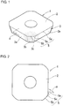
- a cutting insert 1 illustrated is obtained by applying the present invention to a four-cornered, positive, edge-interchangeable cutting insert.
- the cutting insert 1 includes an upper face 2 as a rake face and side faces 3 as flank faces and is mounted on a mounting seat provided around the outer circumference of the tip of a cutter body. Cutting is performed at cutting edges 5 provided as ridges each defined by the upper face 2 and a corresponding one of the side faces 3 that intersect each other.
- the cutting insert 1 is formed by sintering a material such as cemented carbide or cermet.
- the upper face 2 and a lower face 4 each basically have a square shape.
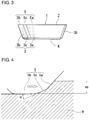
- the cutting edges 5 include major cutting edges 5a each extending linearly between adjacent ones of corners, flat cutting edges 5b provided at the respective corner portions, and minor cutting edges 5c each provided between a corresponding one of the major cutting edges 5a and a corresponding one of the flat cutting edges 5b.
- the major cutting edges 5a are intended for forming a wall surface corresponding to a lateral side portion of a workpiece and each incline at an angle of 45° with respect to the flat cutting edge 5b. This inclination angle is a typical value for a face milling cutter.
- the flat cutting edges 5b are each a cutting edge intended for cutting off feed marks that may be formed in a bottom surface corresponding to a machined surface of the workpiece and thus improving the surface roughness of the bottom surface.
- the minor cutting edges 5c each provided between the major cutting edge 5a and the flat cutting edge 5b may be linear cutting edges or approximately linear curved cutting edges.
- the side faces 3 include side faces 3a that are continuous with the respective major cutting edges 5a, side faces 3b that are continuous with the respective flat cutting edges 5b, and side faces 3c that are continuous with the respective minor cutting edges 5c.
- the side faces 3a, the side faces 3b, and the side faces 3c form a continuous surface while being at angles with respect to one another.
- the side faces 3a that are continuous with the major cutting edges 5a each have higher surface roughness than the side faces 3c that are continuous with the minor cutting edges 5c.
- each minor cutting edge 5c with respect to the flat cutting edge 5b is 10° to 30°. If the inclination angle ⁇ is 10° or larger, chips generated by the minor cutting edges 5c are prevented from becoming too thin. If chips generated by the minor cutting edges 5c become too thin, burrs tend to be formed at the corner portion of the machined surface. Therefore, the inclination angle ⁇ is preferably 10° or larger.
- chips can each have a suitable width in a tool-feeding direction. If chips each have a width that is too small in the tool-feeding direction, the chips are difficult to break. Such chips generated by forming the wall surface corresponding to the lateral side portion of the workpiece tend to reach the machined surface corresponding to the bottom surface and to form burrs. If the inclination angle ⁇ is 30° or smaller, such a problem does not tend to occur.
- the cutting insert to which the present invention is applied is not limited to those basically having square shapes.
- the cutting insert may basically have an equilateral triangular shape, a rectangular shape, or a polygonal shape having four or more corners, or may be a negative cutting insert.
- the illustrated edge-interchangeable cutting insert including a plurality of major cutting edges, a plurality of flat cutting edges, and a plurality of minor cutting edges and in which the positions of the cutting edges are interchangeable by changing the corner to be used is economically superior.
- the effect of suppressing the formation of burrs is also exerted even if the cutting insert includes only one set of a major cutting edge, a flat cutting edge, and a minor cutting edge.
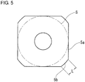
- a cutting insert A (a comparative product), illustrated in Fig. 5 , having a diameter of an inscribed circle S of 13.34 mm and a length L of each flat cutting edge 5b of 3 mm and including no minor cutting edges
- a cutting insert B (a product according to the present invention) obtained by replacing a portion of the flat cutting edge of the cutting insert A with a minor cutting edge having a length of 1 mm and being at an inclination angle ⁇ of 22°30' with respect to the flat cutting edge were experimentally prepared for comparison of the performance of suppressing the formation of burrs.
Landscapes
- Engineering & Computer Science (AREA)
- Mechanical Engineering (AREA)
- Milling Processes (AREA)
Claims (4)
- Plaquette de découpe pour fraisage (1) comprenant des bords de découpe conçus sous forme d'arêtes chacune définie par une face supérieure ou inférieure (2) et une face latérale (3, 3a, 3b, 3c) s'entrecoupant les unes les autres, les bords de découpe comportant un bord de découpe plat (5b) agencé au niveau de l'une des parties de coin, le bord de découpe comprenant un bord de découpe principal (5a) agencé entre des parties adjacentes des parties de coin ; le bord de découpe plat (5b) agencé au niveau de la partie de coin ; et un bord de découpe mineur (5c) agencé entre le bord de découpe principal et le bord de découpe plat et incliné par rapport au bord de découpe plat, caractérisée en ce que
une rugosité moyenne arithmétique de surface d'une face latérale (3a, 3b) qui est continue avec le bord de découpe principal est supérieure à une rugosité moyenne arithmétique de surface d'une face latérale (3c) qui est continue avec le bord de découpe mineur,
dans laquelle la face latérale (3a, 3b) qui est continue avec le bord de découpe principal est une surface non broyée qui est laissée sous la forme d'une surface frittée et la face latérale (3c) qui est continue avec le bord de découpe mineur est une surface broyée. - Plaquette de découpe pour fraisage selon la revendication 1, dans laquelle une rugosité moyenne arithmétique de la face latérale qui est continue avec le bord de découpe mineur (5c) est comprise entre Ra 0,1 µm et 0,3 µm.
- Plaquette de découpe pour fraisage selon la revendication 1 ou 2, dans laquelle un angle d'inclinaison α du bord de découpe mineur (5c) par rapport au bord de découpe plat (5b) est compris entre 10° et 30°.
- Plaquette de découpe pour fraisage selon l'une quelconque des revendications 1 à 3, dans laquelle le bord de découpe principal, le bord de découpe plat (5b) et le bord de découpe mineur (5c) sont l'un d'une pluralité de bords de découpe principaux (5a), l'un d'une pluralité de bords de découpe plats, et l'un d'une pluralité de bords de découpe mineurs, respectivement, et la plaquette de découpe pour fraisage est une plaquette de découpe à bords interchangeables dont les faces supérieure et inférieure ont chacune une forme sensiblement polygonale et dans laquelle les bords de découpe respectifs sont interchangeables en modifiant le coin à utiliser.
Applications Claiming Priority (2)
| Application Number | Priority Date | Filing Date | Title |
|---|---|---|---|
| JP2012257204 | 2012-11-26 | ||
| PCT/JP2013/077884 WO2014080708A1 (fr) | 2012-11-26 | 2013-10-15 | Plaquette de coupe pour fraisage |
Publications (3)
| Publication Number | Publication Date |
|---|---|
| EP2923788A1 EP2923788A1 (fr) | 2015-09-30 |
| EP2923788A4 EP2923788A4 (fr) | 2015-12-30 |
| EP2923788B1 true EP2923788B1 (fr) | 2019-04-03 |
Family
ID=50775897
Family Applications (1)
| Application Number | Title | Priority Date | Filing Date |
|---|---|---|---|
| EP13857233.4A Active EP2923788B1 (fr) | 2012-11-26 | 2013-10-15 | Plaquette de coupe pour fraisage |
Country Status (6)
| Country | Link |
|---|---|
| US (1) | US10124425B2 (fr) |
| EP (1) | EP2923788B1 (fr) |
| JP (1) | JP6217045B2 (fr) |
| CN (1) | CN104203470B (fr) |
| ES (1) | ES2728472T3 (fr) |
| WO (1) | WO2014080708A1 (fr) |
Families Citing this family (8)
| Publication number | Priority date | Publication date | Assignee | Title |
|---|---|---|---|---|
| SE536590C2 (sv) * | 2012-07-05 | 2014-03-11 | Sandvik Intellectual Property | Frässkär med primär och sekundär släppningsyta samt periferisk, smal spånyta |
| US10160083B2 (en) * | 2013-03-29 | 2018-12-25 | Sumitomo Electric Hardmetal Corp. | Method for manufacturing cubic boron nitride cutting tool and cubic boron nitride cutting tool |
| CN106457422A (zh) * | 2014-07-10 | 2017-02-22 | 住友电工硬质合金株式会社 | 切削刀具和面铣刀 |
| EP3023178B1 (fr) * | 2014-11-24 | 2022-05-11 | Sandvik Intellectual Property AB | Procédé de meulage d'un insert de rainurage/séparation et insert de rainurage/séparation |
| JP6457257B2 (ja) * | 2014-12-18 | 2019-01-23 | Dmg森精機株式会社 | フライス工具、及びこれを用いた加工方法 |
| JP6853240B2 (ja) * | 2016-04-25 | 2021-03-31 | 京セラ株式会社 | 切削工具 |
| JP6618025B2 (ja) * | 2016-12-20 | 2019-12-11 | 住友電工ハードメタル株式会社 | 切削工具及びその製造方法 |
| TW202130433A (zh) * | 2020-02-12 | 2021-08-16 | 以色列商艾斯卡公司 | 用於桿件剝層的方形嵌件、及用於它的嵌件固持工具 |
Family Cites Families (17)
| Publication number | Priority date | Publication date | Assignee | Title |
|---|---|---|---|---|
| JPS5112154B2 (fr) * | 1972-02-17 | 1976-04-16 | ||
| JPS60175516U (ja) | 1984-04-28 | 1985-11-20 | 三菱マテリアル株式会社 | 転削工具用スロ−アウエイチツプ |
| GB9010769D0 (en) * | 1990-05-14 | 1990-07-04 | Iscar Hartmetall | Cutting insert |
| SE502541C2 (sv) * | 1992-02-05 | 1995-11-06 | Sandvik Ab | Spånavskiljande skär med exakta lägesbestämmande mått, samt förfarande för dess framställning |
| SE470093B (sv) * | 1992-04-02 | 1993-11-08 | Sandvik Ab | Skär för skiv- eller planfräsar, samt fräsverktyg för sådana skär |
| JP3269245B2 (ja) * | 1994-03-09 | 2002-03-25 | 三菱マテリアル株式会社 | スローアウェイチップ及び切削工具 |
| JP3348534B2 (ja) | 1994-08-12 | 2002-11-20 | 三菱マテリアル株式会社 | スローアウェイ式転削工具 |
| DE69619378T2 (de) * | 1995-07-18 | 2002-10-10 | Sandvik Ab | Werkzeug für metallbearbeitung |
| US5957755A (en) * | 1996-09-30 | 1999-09-28 | Laflamme; Robert | Remanufactured cutting insert and method of remanufacturing the same |
| US6161990A (en) * | 1998-11-12 | 2000-12-19 | Kennametal Inc. | Cutting insert with improved flank surface roughness and method of making the same |
| JP2000288803A (ja) * | 1999-03-31 | 2000-10-17 | Ngk Spark Plug Co Ltd | スローアウェイチップ |
| JP4721644B2 (ja) * | 2004-02-25 | 2011-07-13 | 京セラ株式会社 | ミーリング工具およびその検査方法 |
| JP4511226B2 (ja) * | 2004-03-29 | 2010-07-28 | 京セラ株式会社 | スローアウェイチップ |
| SE530090C2 (sv) | 2006-06-27 | 2008-02-26 | Sandvik Intellectual Property | Planfrässkär med flera bågformiga deleggar och konvexa släppningsytor |
| JP5082422B2 (ja) * | 2006-12-13 | 2012-11-28 | 株式会社タンガロイ | 切削工具 |
| KR100978424B1 (ko) * | 2008-06-26 | 2010-08-26 | 대구텍 유한회사 | 절삭 삽입체 및 그 제조방법 |
| WO2010147157A1 (fr) | 2009-06-16 | 2010-12-23 | 株式会社タンガロイ | Insert de coupe et fraise à surfacer |
-
2013
- 2013-10-15 ES ES13857233T patent/ES2728472T3/es active Active
- 2013-10-15 US US14/382,045 patent/US10124425B2/en active Active
- 2013-10-15 WO PCT/JP2013/077884 patent/WO2014080708A1/fr active Application Filing
- 2013-10-15 CN CN201380016858.0A patent/CN104203470B/zh active Active
- 2013-10-15 EP EP13857233.4A patent/EP2923788B1/fr active Active
- 2013-10-15 JP JP2013557978A patent/JP6217045B2/ja active Active
Non-Patent Citations (1)
| Title |
|---|
| None * |
Also Published As
| Publication number | Publication date |
|---|---|
| CN104203470A (zh) | 2014-12-10 |
| JP6217045B2 (ja) | 2017-10-25 |
| EP2923788A1 (fr) | 2015-09-30 |
| EP2923788A4 (fr) | 2015-12-30 |
| US10124425B2 (en) | 2018-11-13 |
| CN104203470B (zh) | 2017-04-05 |
| JPWO2014080708A1 (ja) | 2017-01-05 |
| US20150043981A1 (en) | 2015-02-12 |
| WO2014080708A1 (fr) | 2014-05-30 |
| ES2728472T3 (es) | 2019-10-24 |
Similar Documents
| Publication | Publication Date | Title |
|---|---|---|
| EP2923788B1 (fr) | Plaquette de coupe pour fraisage | |
| US9555489B2 (en) | Cutting insert and indexable cutting tool | |
| EP2435204B1 (fr) | Plaquette de coupe | |
| JP5844906B2 (ja) | フライス用両面切削インサート | |
| EP2799172B1 (fr) | Fraise en bout arrondie | |
| EP2818269B1 (fr) | Plaquette de coupe et outil de coupe doté d'un bord de coupe remplaçable | |
| JP5853613B2 (ja) | 切削インサート | |
| EP2070620B1 (fr) | Insert de découpe, outil de découpe utilisant cet insert, et procédé de découpe | |
| JP6241636B2 (ja) | 切削インサートおよび刃先交換式切削工具 | |
| EP2431115B1 (fr) | Plaquette de coupe et outil de fraisage à face amovible | |
| US20130129430A1 (en) | Cutting insert and cutting tool | |
| EP2832477B1 (fr) | Plaquette de coupe | |
| CN102548694A (zh) | 切削镶刀及切削工具、以及使用该切削工具的切削加工物的制造方法 | |
| CN110035856B (zh) | 切削刀片和肩铣刀具 | |
| WO2019088125A1 (fr) | Plaquette de coupe et outil de coupe de type à remplacement de bord de coupe | |
| JP2017504495A (ja) | 両面フライス切削インサートおよびフライス工具 | |
| US10525540B2 (en) | Cutting insert and cutting tool | |
| CN103282150A (zh) | 具有限定多个支撑面的开槽面的切削刀片 | |
| KR20110070802A (ko) | 미세 밀링용 정면 밀 | |
| WO2009096516A1 (fr) | Insert de coupe, outil de coupe et méthode de coupe | |
| EP3260225B1 (fr) | Insert de tournage | |
| JP2017530022A (ja) | 旋削用工具の切削インサート及び旋削用工具 | |
| CN105290484A (zh) | 具有可再磨削的切削刀片的旋转切削工具 | |
| JP5196077B2 (ja) | 切削用インサートおよび刃先交換式転削工具 | |
| JP6852258B2 (ja) | 切削インサートおよび刃先交換式切削工具 |
Legal Events
| Date | Code | Title | Description |
|---|---|---|---|
| PUAI | Public reference made under article 153(3) epc to a published international application that has entered the european phase |
Free format text: ORIGINAL CODE: 0009012 |
|
| 17P | Request for examination filed |
Effective date: 20140924 |
|
| AK | Designated contracting states |
Kind code of ref document: A1 Designated state(s): AL AT BE BG CH CY CZ DE DK EE ES FI FR GB GR HR HU IE IS IT LI LT LU LV MC MK MT NL NO PL PT RO RS SE SI SK SM TR |
|
| AX | Request for extension of the european patent |
Extension state: BA ME |
|
| RIC1 | Information provided on ipc code assigned before grant |
Ipc: B23C 5/06 20060101ALI20151109BHEP Ipc: B23C 5/20 20060101AFI20151109BHEP |
|
| RA4 | Supplementary search report drawn up and despatched (corrected) |
Effective date: 20151127 |
|
| DAX | Request for extension of the european patent (deleted) | ||
| GRAP | Despatch of communication of intention to grant a patent |
Free format text: ORIGINAL CODE: EPIDOSNIGR1 |
|
| STAA | Information on the status of an ep patent application or granted ep patent |
Free format text: STATUS: GRANT OF PATENT IS INTENDED |
|
| INTG | Intention to grant announced |
Effective date: 20181123 |
|
| GRAS | Grant fee paid |
Free format text: ORIGINAL CODE: EPIDOSNIGR3 |
|
| GRAA | (expected) grant |
Free format text: ORIGINAL CODE: 0009210 |
|
| STAA | Information on the status of an ep patent application or granted ep patent |
Free format text: STATUS: THE PATENT HAS BEEN GRANTED |
|
| AK | Designated contracting states |
Kind code of ref document: B1 Designated state(s): AL AT BE BG CH CY CZ DE DK EE ES FI FR GB GR HR HU IE IS IT LI LT LU LV MC MK MT NL NO PL PT RO RS SE SI SK SM TR |
|
| REG | Reference to a national code |
Ref country code: GB Ref legal event code: FG4D |
|
| REG | Reference to a national code |
Ref country code: CH Ref legal event code: EP Ref country code: AT Ref legal event code: REF Ref document number: 1115116 Country of ref document: AT Kind code of ref document: T Effective date: 20190415 |
|
| REG | Reference to a national code |
Ref country code: DE Ref legal event code: R096 Ref document number: 602013053458 Country of ref document: DE |
|
| REG | Reference to a national code |
Ref country code: IE Ref legal event code: FG4D |
|
| REG | Reference to a national code |
Ref country code: NL Ref legal event code: MP Effective date: 20190403 |
|
| REG | Reference to a national code |
Ref country code: LT Ref legal event code: MG4D |
|
| REG | Reference to a national code |
Ref country code: AT Ref legal event code: MK05 Ref document number: 1115116 Country of ref document: AT Kind code of ref document: T Effective date: 20190403 |
|
| PG25 | Lapsed in a contracting state [announced via postgrant information from national office to epo] |
Ref country code: NL Free format text: LAPSE BECAUSE OF FAILURE TO SUBMIT A TRANSLATION OF THE DESCRIPTION OR TO PAY THE FEE WITHIN THE PRESCRIBED TIME-LIMIT Effective date: 20190403 |
|
| REG | Reference to a national code |
Ref country code: ES Ref legal event code: FG2A Ref document number: 2728472 Country of ref document: ES Kind code of ref document: T3 Effective date: 20191024 |
|
| PG25 | Lapsed in a contracting state [announced via postgrant information from national office to epo] |
Ref country code: FI Free format text: LAPSE BECAUSE OF FAILURE TO SUBMIT A TRANSLATION OF THE DESCRIPTION OR TO PAY THE FEE WITHIN THE PRESCRIBED TIME-LIMIT Effective date: 20190403 Ref country code: LT Free format text: LAPSE BECAUSE OF FAILURE TO SUBMIT A TRANSLATION OF THE DESCRIPTION OR TO PAY THE FEE WITHIN THE PRESCRIBED TIME-LIMIT Effective date: 20190403 Ref country code: AL Free format text: LAPSE BECAUSE OF FAILURE TO SUBMIT A TRANSLATION OF THE DESCRIPTION OR TO PAY THE FEE WITHIN THE PRESCRIBED TIME-LIMIT Effective date: 20190403 Ref country code: CZ Free format text: LAPSE BECAUSE OF FAILURE TO SUBMIT A TRANSLATION OF THE DESCRIPTION OR TO PAY THE FEE WITHIN THE PRESCRIBED TIME-LIMIT Effective date: 20190403 Ref country code: SE Free format text: LAPSE BECAUSE OF FAILURE TO SUBMIT A TRANSLATION OF THE DESCRIPTION OR TO PAY THE FEE WITHIN THE PRESCRIBED TIME-LIMIT Effective date: 20190403 Ref country code: NO Free format text: LAPSE BECAUSE OF FAILURE TO SUBMIT A TRANSLATION OF THE DESCRIPTION OR TO PAY THE FEE WITHIN THE PRESCRIBED TIME-LIMIT Effective date: 20190703 Ref country code: HR Free format text: LAPSE BECAUSE OF FAILURE TO SUBMIT A TRANSLATION OF THE DESCRIPTION OR TO PAY THE FEE WITHIN THE PRESCRIBED TIME-LIMIT Effective date: 20190403 Ref country code: PT Free format text: LAPSE BECAUSE OF FAILURE TO SUBMIT A TRANSLATION OF THE DESCRIPTION OR TO PAY THE FEE WITHIN THE PRESCRIBED TIME-LIMIT Effective date: 20190803 |
|
| PG25 | Lapsed in a contracting state [announced via postgrant information from national office to epo] |
Ref country code: GR Free format text: LAPSE BECAUSE OF FAILURE TO SUBMIT A TRANSLATION OF THE DESCRIPTION OR TO PAY THE FEE WITHIN THE PRESCRIBED TIME-LIMIT Effective date: 20190704 Ref country code: PL Free format text: LAPSE BECAUSE OF FAILURE TO SUBMIT A TRANSLATION OF THE DESCRIPTION OR TO PAY THE FEE WITHIN THE PRESCRIBED TIME-LIMIT Effective date: 20190403 Ref country code: LV Free format text: LAPSE BECAUSE OF FAILURE TO SUBMIT A TRANSLATION OF THE DESCRIPTION OR TO PAY THE FEE WITHIN THE PRESCRIBED TIME-LIMIT Effective date: 20190403 Ref country code: RS Free format text: LAPSE BECAUSE OF FAILURE TO SUBMIT A TRANSLATION OF THE DESCRIPTION OR TO PAY THE FEE WITHIN THE PRESCRIBED TIME-LIMIT Effective date: 20190403 Ref country code: BG Free format text: LAPSE BECAUSE OF FAILURE TO SUBMIT A TRANSLATION OF THE DESCRIPTION OR TO PAY THE FEE WITHIN THE PRESCRIBED TIME-LIMIT Effective date: 20190703 |
|
| PG25 | Lapsed in a contracting state [announced via postgrant information from national office to epo] |
Ref country code: AT Free format text: LAPSE BECAUSE OF FAILURE TO SUBMIT A TRANSLATION OF THE DESCRIPTION OR TO PAY THE FEE WITHIN THE PRESCRIBED TIME-LIMIT Effective date: 20190403 Ref country code: IS Free format text: LAPSE BECAUSE OF FAILURE TO SUBMIT A TRANSLATION OF THE DESCRIPTION OR TO PAY THE FEE WITHIN THE PRESCRIBED TIME-LIMIT Effective date: 20190803 |
|
| REG | Reference to a national code |
Ref country code: DE Ref legal event code: R097 Ref document number: 602013053458 Country of ref document: DE |
|
| PG25 | Lapsed in a contracting state [announced via postgrant information from national office to epo] |
Ref country code: EE Free format text: LAPSE BECAUSE OF FAILURE TO SUBMIT A TRANSLATION OF THE DESCRIPTION OR TO PAY THE FEE WITHIN THE PRESCRIBED TIME-LIMIT Effective date: 20190403 Ref country code: RO Free format text: LAPSE BECAUSE OF FAILURE TO SUBMIT A TRANSLATION OF THE DESCRIPTION OR TO PAY THE FEE WITHIN THE PRESCRIBED TIME-LIMIT Effective date: 20190403 Ref country code: DK Free format text: LAPSE BECAUSE OF FAILURE TO SUBMIT A TRANSLATION OF THE DESCRIPTION OR TO PAY THE FEE WITHIN THE PRESCRIBED TIME-LIMIT Effective date: 20190403 Ref country code: SK Free format text: LAPSE BECAUSE OF FAILURE TO SUBMIT A TRANSLATION OF THE DESCRIPTION OR TO PAY THE FEE WITHIN THE PRESCRIBED TIME-LIMIT Effective date: 20190403 |
|
| PLBE | No opposition filed within time limit |
Free format text: ORIGINAL CODE: 0009261 |
|
| STAA | Information on the status of an ep patent application or granted ep patent |
Free format text: STATUS: NO OPPOSITION FILED WITHIN TIME LIMIT |
|
| PG25 | Lapsed in a contracting state [announced via postgrant information from national office to epo] |
Ref country code: SM Free format text: LAPSE BECAUSE OF FAILURE TO SUBMIT A TRANSLATION OF THE DESCRIPTION OR TO PAY THE FEE WITHIN THE PRESCRIBED TIME-LIMIT Effective date: 20190403 |
|
| 26N | No opposition filed |
Effective date: 20200106 |
|
| PG25 | Lapsed in a contracting state [announced via postgrant information from national office to epo] |
Ref country code: TR Free format text: LAPSE BECAUSE OF FAILURE TO SUBMIT A TRANSLATION OF THE DESCRIPTION OR TO PAY THE FEE WITHIN THE PRESCRIBED TIME-LIMIT Effective date: 20190403 |
|
| PG25 | Lapsed in a contracting state [announced via postgrant information from national office to epo] |
Ref country code: MC Free format text: LAPSE BECAUSE OF FAILURE TO SUBMIT A TRANSLATION OF THE DESCRIPTION OR TO PAY THE FEE WITHIN THE PRESCRIBED TIME-LIMIT Effective date: 20190403 Ref country code: SI Free format text: LAPSE BECAUSE OF FAILURE TO SUBMIT A TRANSLATION OF THE DESCRIPTION OR TO PAY THE FEE WITHIN THE PRESCRIBED TIME-LIMIT Effective date: 20190403 |
|
| REG | Reference to a national code |
Ref country code: CH Ref legal event code: PL |
|
| PG25 | Lapsed in a contracting state [announced via postgrant information from national office to epo] |
Ref country code: LU Free format text: LAPSE BECAUSE OF NON-PAYMENT OF DUE FEES Effective date: 20191015 Ref country code: LI Free format text: LAPSE BECAUSE OF NON-PAYMENT OF DUE FEES Effective date: 20191031 Ref country code: CH Free format text: LAPSE BECAUSE OF NON-PAYMENT OF DUE FEES Effective date: 20191031 |
|
| REG | Reference to a national code |
Ref country code: BE Ref legal event code: MM Effective date: 20191031 |
|
| PG25 | Lapsed in a contracting state [announced via postgrant information from national office to epo] |
Ref country code: BE Free format text: LAPSE BECAUSE OF NON-PAYMENT OF DUE FEES Effective date: 20191031 |
|
| GBPC | Gb: european patent ceased through non-payment of renewal fee |
Effective date: 20191015 |
|
| PG25 | Lapsed in a contracting state [announced via postgrant information from national office to epo] |
Ref country code: IE Free format text: LAPSE BECAUSE OF NON-PAYMENT OF DUE FEES Effective date: 20191015 Ref country code: GB Free format text: LAPSE BECAUSE OF NON-PAYMENT OF DUE FEES Effective date: 20191015 |
|
| PG25 | Lapsed in a contracting state [announced via postgrant information from national office to epo] |
Ref country code: CY Free format text: LAPSE BECAUSE OF FAILURE TO SUBMIT A TRANSLATION OF THE DESCRIPTION OR TO PAY THE FEE WITHIN THE PRESCRIBED TIME-LIMIT Effective date: 20190403 |
|
| PG25 | Lapsed in a contracting state [announced via postgrant information from national office to epo] |
Ref country code: HU Free format text: LAPSE BECAUSE OF FAILURE TO SUBMIT A TRANSLATION OF THE DESCRIPTION OR TO PAY THE FEE WITHIN THE PRESCRIBED TIME-LIMIT; INVALID AB INITIO Effective date: 20131015 Ref country code: MT Free format text: LAPSE BECAUSE OF FAILURE TO SUBMIT A TRANSLATION OF THE DESCRIPTION OR TO PAY THE FEE WITHIN THE PRESCRIBED TIME-LIMIT Effective date: 20190403 |
|
| PGFP | Annual fee paid to national office [announced via postgrant information from national office to epo] |
Ref country code: IT Payment date: 20210910 Year of fee payment: 9 Ref country code: FR Payment date: 20210913 Year of fee payment: 9 |
|
| PG25 | Lapsed in a contracting state [announced via postgrant information from national office to epo] |
Ref country code: MK Free format text: LAPSE BECAUSE OF FAILURE TO SUBMIT A TRANSLATION OF THE DESCRIPTION OR TO PAY THE FEE WITHIN THE PRESCRIBED TIME-LIMIT Effective date: 20190403 |
|
| P01 | Opt-out of the competence of the unified patent court (upc) registered |
Effective date: 20230515 |
|
| PG25 | Lapsed in a contracting state [announced via postgrant information from national office to epo] |
Ref country code: FR Free format text: LAPSE BECAUSE OF NON-PAYMENT OF DUE FEES Effective date: 20221031 |
|
| PG25 | Lapsed in a contracting state [announced via postgrant information from national office to epo] |
Ref country code: IT Free format text: LAPSE BECAUSE OF NON-PAYMENT OF DUE FEES Effective date: 20221015 |
|
| PGFP | Annual fee paid to national office [announced via postgrant information from national office to epo] |
Ref country code: ES Payment date: 20231102 Year of fee payment: 11 |
|
| PGFP | Annual fee paid to national office [announced via postgrant information from national office to epo] |
Ref country code: DE Payment date: 20230830 Year of fee payment: 11 |