EP2923211B1 - Verfahren und vorrichtung zum prüfen eines werkstücks - Google Patents
Verfahren und vorrichtung zum prüfen eines werkstücks Download PDFInfo
- Publication number
- EP2923211B1 EP2923211B1 EP13811135.6A EP13811135A EP2923211B1 EP 2923211 B1 EP2923211 B1 EP 2923211B1 EP 13811135 A EP13811135 A EP 13811135A EP 2923211 B1 EP2923211 B1 EP 2923211B1
- Authority
- EP
- European Patent Office
- Prior art keywords
- testing
- holder
- pin
- test
- workpiece
- Prior art date
- Legal status (The legal status is an assumption and is not a legal conclusion. Google has not performed a legal analysis and makes no representation as to the accuracy of the status listed.)
- Active
Links
Images


Classifications
-
- G—PHYSICS
- G01—MEASURING; TESTING
- G01R—MEASURING ELECTRIC VARIABLES; MEASURING MAGNETIC VARIABLES
- G01R31/00—Arrangements for testing electric properties; Arrangements for locating electric faults; Arrangements for electrical testing characterised by what is being tested not provided for elsewhere
- G01R31/28—Testing of electronic circuits, e.g. by signal tracer
- G01R31/2801—Testing of printed circuits, backplanes, motherboards, hybrid circuits or carriers for multichip packages [MCP]
- G01R31/2806—Apparatus therefor, e.g. test stations, drivers, analysers, conveyors
- G01R31/2808—Holding, conveying or contacting devices, e.g. test adapters, edge connectors, extender boards
-
- G—PHYSICS
- G01—MEASURING; TESTING
- G01R—MEASURING ELECTRIC VARIABLES; MEASURING MAGNETIC VARIABLES
- G01R1/00—Details of instruments or arrangements of the types included in groups G01R5/00 - G01R13/00 and G01R31/00
- G01R1/02—General constructional details
- G01R1/06—Measuring leads; Measuring probes
- G01R1/067—Measuring probes
- G01R1/06705—Apparatus for holding or moving single probes
Definitions
- the invention relates to a method and a device for testing a workpiece, in particular a printed circuit board, according to the preamble of claim 1 and 4, respectively, as well as to a use of an intrinsically active polymer according to claim 9.
- testing devices are known and commercially available in a wide variety of forms and designs.
- the present invention relates to any testing device with which a workpiece is to be scanned by a plurality of test pins arranged in a specific relationship to one another, although this arrangement may need to be changed.
- the present invention relates to testing devices for examining electronic circuit boards for defects and functionality before they are installed in electronic devices.
- contact pins or needles are pressed into predetermined locations (contact positions) on the circuit board and then subjected to test signals according to a predetermined control system by a test computer to determine the functionality of the populated circuit board.
- a test computer to determine the functionality of the populated circuit board.
- Such testing facilities are used, for example, in DE 11 2006 003 034 T5 or the DE 196 46 252 A1 or the DE 44 16 151 B described.
- all of these devices require that the circuit boards to be tested be precisely assigned to the test pins. Since a large number of such tests must be performed within a single time unit, significant problems arise with the positioning of the circuit board in relation to the test pins.
- test adapter with the test pins must also be subsequently redesigned, which takes a long time because, for example, the angle of attack and the arrangement of the test pins relative to each other must be recalculated. and the corresponding supports, e.g. perforated plates, must be redesigned.
- a test probe is moved by an actuator.
- This essentially consists of a coil that generates a magnetic field and causes the test probe to deflect.
- test pin is known that is equipped with two tips, one of which is arranged eccentrically to the first. When the test pin is rotated, this second tip rotates around the first tip.
- Corresponding test needles are coupled with carriages which can pivot the needles in the X and Y directions.
- microactuators are embedded in a substrate, which can be a hydrogel polymer.
- This hydrogel polymer is designed to react to environmental influences. As a result of these environmental influences, the microactuators move from a first to a second position due to a change in the volume of the hydrogel polymer.
- the WO 2008 113372 A2 shows a device with an actuator made of an electroactive polymer.
- the device has two parts that are separated from each other by the actuator.
- the object of the present invention is to develop a method and a device of the above-mentioned type that facilitate and, in particular, accelerate changes in the relative arrangement of test pins.
- the object of the present invention is also to improve the movement of test pins, especially in the field of electronics but also in micromechanics.
- Intrinsically active polymers are plastics that change their material properties in a defined manner when exposed to certain physical (e.g., temperature, light of a specific wavelength, electric and magnetic fields) or chemical (substance concentrations, pH) environmental parameters. These include, in particular, phase-reversible polymers (e.g., stimulus-sensitive hydrogels, polymer brushes), phase-change polymers, conductive polymers, and bielectric elastomers. Other examples of intrinsically active polymers include shape memory polymers, piezoelectric polymers, electrostrictive polymers, and ferroelectric polymers.
- the present invention primarily utilizes electroactive or so-called stimuli-sensitive hydrogels. These materials are solid-state effect carriers with the largest volume change usable for actuators and are therefore extremely easy to miniaturize.
- the temperature-sensitive poly-(N-isopropylacrylamide) (PNIPAAm) is used as the basis.
- the mechanical and actuator properties of the actuator material are tailored to specific drive tasks.
- the expected The mechanical stresses will exceed the achievable properties of the PNIPAAm homopolymer. Therefore, the polymer is functionalized with special nanomaterials from the group of layered silicates, which leads to an improvement in the mechanical-actuating hydrogel properties by more than an order of magnitude.
- the parameters of the active polymer are optimized by varying the crosslinking conditions and specifically modifying the starting materials, the degree of crosslinking, and the porosity of the crosslinking points.
- the hydrogel actuators In their unmodified state, the hydrogel actuators can be switched from a fully swollen to a fully deflated state within their volume phase transition region by varying the actuator temperature by just 5 K. To achieve high-precision actuator control, it may be necessary to expand the volume phase transition range, for example, to 10 K. This can be achieved by copolymerizing the N-isopropylacrylamide or by varying the thermodynamic quality of the solvent.
- the actuator material should be microstructureable.
- the invention uses radical photopolymerization, which not only synthesizes the hydrogel but also microstructures it to give it its shape.
- actuator material Another aspect is the actuator material's ability to integrate into a higher-level system. This involves ensuring the necessary material compatibility and finding suitable adhesion promoter systems for covalent adhesion.
- the main purpose of the present invention is to apply these polymers to a holder using a screen-printing process so that they can surround the corresponding test pins. When they are then confronted with or exposed to a corresponding physical or chemical environmental parameter, they change their position in a defined manner like a muscle, thereby moving the test pin.
- the idea is, of course, to precisely monitor the changes in the test pins. This is done using appropriate cameras.
- the main idea is that the test pin is guided directly through a camera lens, so that the camera can precisely observe the movement of the test pin.
- test pin 2 is located on a holder 1, whereby it can naturally be assumed that a plurality of such test pins 2 are generally provided on this holder 1.
- This test pin 2 is intended to test a printed circuit board 3.
- the test pin 2 with a shaft 4 penetrates the holder 1, which is designed as a perforated plate.
- This shaft 4 is arranged in a corresponding recess in the perforated plate 1, rotatable about an axis A.
- a test probe 5 is located eccentrically to this axis A, the position of which relative to the workpiece (circuit board 3) can be changed when the shaft 4 is rotated.
- the recess could be an elongated hole or the like.
- a magnet 6 is provided on the shaft 4.
- the perforated plate 1 is preferably at least partially magnetic, so that an attractive force acts between the magnet 6 and the perforated plate 1, as indicated by the arrows.
- the shaft 4 is turned by a key (not shown in detail) which is attached to an auxiliary square adjustment 7 can be placed. If a different position of the test probe 5 relative to the circuit board 3 is desired, the key can be used to rotate the test pin 2 about its axis A and to move the test probe 5 in a circular motion. At the same time, or in addition, it is also possible to move either the perforated plate 1 and/or the circuit board 3 horizontally two-dimensionally, so that each point on the circuit board 3 can be approached with the test probe 5. Such a movement mechanism for the circuit board 3 is described, for example, in the DE 10 2012 106 291.9 shown.
- the perforated plate 1 is additionally assigned a fixing plate 8, wherein a distance a between the perforated plate 1 and the fixing plate 8 is adjustable.
- This fixing plate 8 has, among other things, the task of fixing the individual test pins 2 relative to the perforated plate 1 after they have been adjusted, ie it essentially supports the magnet 6 so that the test pins 2 are not lifted off the perforated plate 1 when they are lowered onto the circuit board 3 and the position of the test pins 2 is not accidentally changed.
- a semi-magnetic plate is used as the holder 1.1. This means that the basic position of the test pins 2.1 in this case does not depend on the hole pattern of a perforated plate, but rather the test pin 2.1 can be moved freely along a bottom surface 9 of the holder 1.1.
- Rotation of the test pin 2.1 about its axis A is effected by a drive magnet 10, which is assigned to the holder 1.1 beyond the test pin 2.1.
- This drive magnet 10 can be moved in any direction along the holder 1.1, but can also be rotated so that the magnet 6 follows it, thus allowing the test pin 2.1 to be aligned with a printed circuit board (not shown).
- a magnetically conductive fixing plate 8.1 is provided, with which the entire arrangement can be fixed.
- the device for testing a workpiece according to Figure 4 differs from that according to Figure 3 only by arranging an additional tool 11 with which another task can be performed.
- this could be a spring-loaded hold-down device that presses against the workpiece or a camera that monitors the test probe 5.
- test pin 2.2 is located on a carriage 11, which can be moved in any way.
- a carriage 11 which can be moved in any way.
- the DE 10 2012 106 291.9 The movement of the carriage 11 or the position of the test pin 2.2 relative to the circuit board 3 can be observed and monitored by a separate camera 12 and/or by a camera 13 assigned to the carriage 11.
- test pin 2 or a test probe 5 directly penetrates the lens 14 of a camera, so that this lens 14 is directly aligned with an impact point 15 of the test probe 5 on the circuit board 3.
- EAP electroactive polymers
- a corresponding test pin 2 is guided in a perforated plate 1.
- the corresponding EAP actuator surrounds the test pin 2, with the EAP actuator 16 itself being Figure 10 is exposed to an electric field from four sides. This causes, for example, Figure 11 that a central region of the EAP actuator bulges and thereby lifts the test pin 2.
- a rotation of the test pin 2 can also be caused.
- test pin 2 is integrated into a housing 17, wherein the test pin 2 is surrounded by an EAP actuator 16 in the upper area or within the housing 17.
- test pins 2 protrude from the housing 17. These contact needles or test pins 2 are enclosed by a polymer reactor 16, which is embedded in the housing 17.
- This hydrogel-based actuator has the task of positioning the contact needle freely in the xy plane with a positioning accuracy of approximately 25 ⁇ m and maximum positioning ranges of +/- 500 ⁇ m starting from the normal position.
- This complex multi-axial positioning can be achieved with a flexible solid-state reactor, which, when appropriately controlled, deforms in an analog manner so that it can move to any point in the positioning plane via the contact needle. This requires finding a suitable structural design and dimensions.
- the achievable positioning accuracy is also determined by the performance of the actuator control electrodes.
- the resistive control electrodes are segmented and control the temperature field, which can be electronically rotated through 360°. Key investigation criteria are the number of electrodes required to position the contact needles with sufficient precision, the required heating power, the course of the thermal field, the heat coupling, and the thermal management to stabilize the controlled temperature field.
- the contact needle positioning drive is only responsible for the actual positioning process. Once the contact needle has reached its final position, a locking mechanism is activated, securing the needles in place.
- Active temperature management can be achieved, for example, using Peltier elements or active water cooling.
- the drive housing not only provides mechanical protection for the positioning drive, but also carries its mechanical and electrical interfaces.
- the head must also have adjustment options to enable it to be optimally set or pre-positioned.
- adjustment options to enable it to be optimally set or pre-positioned.
- For the positioning drives Ideally, a global adjustment can be realized; alternatively, concepts for individual adjustment are investigated.
Landscapes
- Engineering & Computer Science (AREA)
- Physics & Mathematics (AREA)
- General Physics & Mathematics (AREA)
- Computer Hardware Design (AREA)
- Microelectronics & Electronic Packaging (AREA)
- General Engineering & Computer Science (AREA)
- Measuring Leads Or Probes (AREA)
- Investigating Strength Of Materials By Application Of Mechanical Stress (AREA)
- Tests Of Electronic Circuits (AREA)
Description
- Die Erfindung betrifft ein Verfahren und eine Vorrichtung zum Prüfen eines Werkstücks, insbesondere einer Leiterplatte, entsprechend dem Oberbegriff von Anspruch 1 bzw. 4, sowie eine Verwendung von einem intrinsisch aktiven Polymer nach Anspruch 9.
- In vielen Fällen des täglichen Lebens müssen Gegenstände bewegt werden. Nur beispielsweise wird nachfolgend auf elektronische Prüfvorrichtungen verwiesen. Darauf soll aber für die Erfindung nicht beschränkt sein. Die Beschreibung ist nur beispielhaft zu sehen. Ebenfalls nicht einschränkend bezieht sich die vorliegende Erfindung auf Bewegungen, die in Miniaturbereichen stattfinden. Hierfür ist sie besonders gut geeignet.
- Derartige Prüfvorrichtungen sind in vielfältiger Form und Ausführung bekannt und auf dem Markt. Die vorliegende Erfindung bezieht sich auf jede Prüfvorrichtung, mit der ein Werkstück durch eine Mehrzahl von Prüfstiften abgetastet werden soll, die in einem bestimmten Verhältnis zueinander angeordnet sind, diese Anordnung aber ggf. geändert werden muss. Vor allem, aber nicht ausschliesslich bezieht sich die vorliegende Erfindung auf Prüfvorrichtungen zum Untersuchen von elektronischen Leiterplatten auf Fehler und Funktion vor dem Einbau in elektronische Geräte.
- In solchen Vorrichtungen werden Kontaktstifte oder -nadeln an vorbestimmten Stellen (Kontaktpositionen) der Leiterplatte angedrückt und dann entsprechend einer vorbestimmten Steuerung durch einen Prüfcomputer mit Prüfsignalen beaufschlagt, um die Funktionstüchtigkeit der bestückten Leiterplatte zu ermitteln. Um einen einwandfreien, elektrischen Kontakt zwischen den Kontaktnadeln und Kontaktstellen auf einer Leiterplatte herzustellen, die eine grosse Anzahl von Kontaktpositionen abgreift, sind oftmals mehrere tausend Kontaktnadeln notwendig bzw. möglich.
- Derartige Prüfeinrichtungen sind beispielsweise in der
DE 11 2006 003 034 T5 oder auch derDE 196 46 252 A1 oder derDE 44 16 151 B beschrieben. All diese Geräte setzen aber voraus, dass die zu prüfenden Leiterplatten exakt den Prüfstiften zugeordnet werden. Da innerhalb einer Zeiteinheit auch eine Vielzahl derartiger Prüfungen stattfinden müssen, kommt es zu erheblichen Problemen bei der Positionierung der Leiterplatte im Verhältnis zu den Prüfstiften. - Ein häufig auftretendes Problem bei derartigen Prüfeinrichtung, insbesondere für Leiterplatten, ist, dass das zu prüfende Werkstück nachträglich abgeändert wird. Das bedeutet, dass auch der Prüfadapter mit den Prüfstiften nachträglich neu designed werden muss, was lange Zeit in Anspruch nimmt, da z.B. Anstellwinkel und Anordnung der Prüfstifte zueinander neu berechnet werden müssen und auch die entsprechenden Halterungen, z.B. Lochplatten, neu designed werden müssen.
- Aus der
US 5 635 849 A ist beispielsweise bekannt, dass eine Prüfspitze durch einen Aktuator bewegt wird. Dieser beinhaltet im wesentlichen eine Spule, die ein magnetisches Feld erzeugt und eine Deflektion der Prüfspitze bewirkt. - Aus der
US 7 091 730 B1 ist ein Prüfstift bekannt, der mit zwei Spitzen versehen ist, wobei eine Prüfspitze exzentrisch zur ersten angeordnet ist. Bei Drehen des Prüfstifts dreht sich diese zweite Spitze um die erste Spitze. - Aus der
US 2002/0013667 A1 ist eine elektrische Testeinrichtung für eine Leiterplatte bekannt, wobei eine Vielzahl von Prüfstiften vorgesehen sind, die auf elektromagnetischem Wege in allen drei Richtungen bewegt werden können. - Bei der
DE 195 03 329 A1 sind entsprechende Prüfnadeln mit Schlitten gekoppelt, welche die Nadeln in X- und Y-Richtung schwenken können. - Aus der
WO 2012 075033 A2 ist eine Strukturanordnung bekannt, welche Mikroaktuatoren aufweist. Diese sind eingebettet in ein Substrat, welches ein Hydrogelpolymer sein kann. Dieses Hydrogelpolymer soll auf Umwelteinflüsse reagieren. Infolge dieser Umwelteinflüsse bewegen sich die Mikroaktuatoren von einer ersten in eine zweite Position aufgrund von einem Volumenwechsel des Hydrogelpolymers. - Die
WO 2008 113372 A2 zeigt eine Vorrichtung mit einem Aktuator aus einem elektroaktiven Polymer. Dabei weist die Vorrichtung zwei Teile auf, welche durch den Aktuator voneinander getrennt werden. - Aufgabe der vorliegenden Erfindung ist es, ein Verfahren und eine Vorrichtung der o.g. Art zu entwickeln, mit denen eine Änderung der Anordnung der Prüfstifte zueinander erleichtert und insbesondere beschleunigt wird. Aufgabe der vorliegenden Erfindung ist es auch, die Bewegung von Prüfstiften vor allem auf dem Gebiete der Elektronik aber auch der Mikromechanik zu verbessern.
- Zur Lösung der Aufgabe führen die Merkmale des Anspruchs 1, 4 bzw. 9.
- Intrinsisch aktive Polymere sind Kunststoffe, welche bei Einwirken bestimmter physikalischer (z.B. Temperatur, Licht bestimmter Wellenlänge, elektrische und magnetische Feldgrössen) oder chemischer (Stoffkonzentrationen, pH-Wert) Umgebungsgrössen Materialeigenschaften definiert ändern. Vor allem sind dies phasenreversible Polymere (z.B. stimuli-sensitive Hydrogele, Polymerbürsten) phasenveränderliche Polymere, leitfähige Polymere sowie bi-lektrische Elastomere. Weitere Vertreter der intrinsisch aktiven Polymere sind Formgedächtnispolymere, piezoelektrische Polymere, elektrostrikitve Polymere sowie ferroelektrische Polymere.
- Die vorliegende Erfindung verwendet vor allem elektroaktive oder sogenannte stimuli-sensitive Hydrogele. Diese Materialien sind Festkörpereffektträger mit der grössten aktorisch nutzbaren Volumenänderung und deshalb ausserordentlich gut miniaturisierbar.
- Als Basis wird das temperatursensitive Poly-(N-Isopropylacrylamid) (PNIPAAm) genutzt.
- In einem ersten Schritt gemäss der vorliegenden Erfindung werden die mechanischen und aktorischen Eigenschaften des Aktormaterials auf spezifizierte Antriebsaufgaben zugeschnitten. Die zu erwartenden mechanischen Beanspruchungen werden die erreichbaren Eigenschaften des Homopolymers PNIPAAm übersteigen. Deshalb wird das Polymer mit speziellen Nanomaterialien aus der Gruppe der Schichtsilikate funktionalisiert, was zu einer Verbesserung der mechanisch-aktorischen Hydrogeleigenschaften um mehr als eine Grössenordnung führt. Die Parameteroptimierung des aktiven Polymers erfolgt durch Variation der Vernetzungsbedingungen und spezifische Modifikation der Ausgangsstoffe, des Vernetzungsgrades und der Porosität der Vernetzungspunkte.
- Des weiteren wurde die Steuerbarkeit der Aktormaterialien optimiert. Im unmodifizierten Zustand lassen sich die Hydrogelaktoren im Bereich ihres Volumenphasenübergangs durch Variation der Aktortemperatur um lediglich 5 K vom vollständig gequollenen zum völlig entquollenen Zustand schalten. Um die Aktorsteuerung hochpräzise durchzuführen, kann der Bedarf entstehen, den Volumenphasenübergangsbereich z.B. auf 10 K aufzuweiten. Dies ist einerseits durch Co-Polymerisation des N-Isopropylacrylamids, andererseits aber auch durch die Variation der thermodynamischen Qualität des Lösungsmittels erreichbar.
- Darüber hinaus sollte das Aktormaterial mikrostrukturierbar sein. Dafür wird erfindungsgemäss eine radikalische Photopolymerisation verwendet, mit der das Hydrogel nicht nur synthetisiert, sondern auch formgebend mikrostrukturiert wird.
- Ein weiterer Aspekt ist die Integrationsfähigkeit des Aktormaterials in ein übergeordnetes System. Hier sind einerseits die erforderlichen Materialkompatibilitäten zu gewährleisten, andererseits für die kovalente Haftung geeignete Haftvermittlersysteme zu finden.
- Eine Vorrichtung bzw. ein Positionierantrieb zur Durchführung des Verfahrens ist als kompaktes, voll integriertes System konzipiert und umfasst folgende Baugruppen:
- (i) zumindest ein Aktor,
- (ii) Aktor-Steuerelektroden,
- (iii) einen Arretiermechanismus,
- (iv) ein Antriebsgehäuse inklusive mechanische Schnittstellen,
- (v) zumindest eine Schnittstellen zu übergeordneten Systemen und
- (vi) eine hard- und softwarebasierte Steuerung des Positionierantriebs.
- Im Rahmen der vorliegenden Erfindung liegt vor allem, diese Polymere im Siebdruckverfahren auf eine Halterung aufzubringen, damit sie dort die entsprechenden Prüfstifte umgeben können. Werden sie dann mit einer entsprechenden physikalischen oder chemischen Umgebungsgrösse konfrontiert bzw. beaufschlagt, ändern sie definiert Ihre Lage wie ein Muskel und bewegen dabei den Prüfstift.
- Insgesamt ist natürlich daran gedacht, die Änderungen der Prüfstifte genauestens zu beobachten. Dies geschieht durch entsprechende Kameras, wobei im Rahmen der vorliegenden Erfindung vor allem daran gedacht ist, dass der Prüfstift direkt durch ein Objektiv der Kamera hindurchgeführt ist, so dass diese Kamera genauestens die Bewegung des Prüfstiftes beobachten kann.
- Weitere Vorteile, Merkmale und Einzelheiten der Erfindung ergeben sich aus der nachfolgenden Beschreibung bevorzugter Ausführungsbeispiele sowie anhand der Zeichnung; diese zeigt in
-
Figur 1 eine schematische Seitenansicht auf einen Teil einer Vorrichtung zum Prüfen eines Werkstücks; -
Figur 2 - 5 schematische Seitenansichten von weiteren Ausführungsbeispielen von Vorrichtungen zum Prüfen von Werkstücks; -
Figur 6 eine schematische Seitenansicht einer Anordnung zum Beobachten von Prüfstiften; -
Figur 7 eine schematische Seitenansicht einer weiteren Anordnung zum Überwachen der Tätigkeit von Prüfstiften; -
Figur 8 eine schematisch dargestellte Seitenansicht eines weiteren Ausführungsbeispiels eines Teils einer Vorrichtung zum Prüfen eines Werkstücks; -
Figur 9 eine Draufsicht auf eine Halterung für Prüfstifte; -
Figur 10 und 11 eine schematisch dargestellte Draufsicht und Seitenansicht auf einen Ausschnitt vonFigur 9 mit elektroaktiven Polymeraktivatoren; -
Figur 12 eine perspektivisch dargestellte Draufsicht auf einen prinzipiellen Aufbau eines mehraxialen Positionierantriebs; -
Figur 13 eine perspektivisch dargestellte Seitenansicht eines erfindungsgemässen Kontaktnadelkopfes; - Figur 14 eine perspektivische Ansicht eines Kontaktnadelkopfes;
- Figur 15 eine perspektivische Ansicht eines mehraxialen Positionierantriebs mit Kontaktnadel.
- Gemäss
Figur 1 befindet sich an einer Halterung 1 ein Prüfstift 2, wobei natürlich davon auszugehen ist, dass an dieser Halterung 1 in der Regel eine Vielzahl derartiger Prüfstifte 2 vorgesehen ist. Mit diesem Prüfstift 2 soll eine Leiterplatte 3 geprüft werden. - Der Prüfstift 2 durchsetzt mit einem Schaft 4 die Halterung 1, die als Lochplatte ausgebildet ist. Dieser Schaft 4 ist in einer entsprechenden Ausnehmung in der Lochplatte 1 drehbar um eine Achse A angeordnet. Zu dieser Achse A exzentrisch befindet sich eine Prüfspitze 5, die bei Drehung des Schaftes 4 in ihrer Lage gegenüber dem Werkstück (Leiterplatte 3) verändert werden kann. Selbstverständlich ist es zusätzlich möglich, auch die Ausnehmung in der Lochplatte 1, welche von dem Schaft 4 durchsetzt wird, entsprechend auszubilden, so dass zusätzlich die Lage der Prüfspitze 5 verändert werden kann. Beispielsweise könnte die Ausnehmung ein Langloch od. dgl. sein.
- Zur Fixierung des Prüfstifts 2 gegenüber der Lochplatte 1 ist ein Magnet 6 auf dem Schaft 4 vorgesehen. In diesem Fall ist bevorzugt die Lochplatte 1 zumindest teilweise magnetisch ausgebildet, so dass zwischen dem Magnet 6 und der Lochplatte 1, wie durch die Pfeile angedeutet, eine Anziehungskraft wirkt.
- Es geschieht das Drehen des Schaftes 4 durch einen nicht näher gezeigten Schlüssel, der auf einen Justage-Hilfsvierkant 7 aufgesetzt werden kann. Wird somit eine andere Lage der Prüfspitze 5 gegenüber der Leiterplatte 3 gewünscht, so kann durch den Schlüssel der Prüfstift 2 um seine Achse A gedreht und die Prüfspitze 5 kreisförmig bewegt werden. Gleichzeitig bzw. zusätzlich ist auch daran gedacht, entweder die Lochplatte 1 und/oder die Leiterplatte 3 in der Waagrechten zweidimensional zu bewegen, so dass dadurch jeder Punkt auf der Leiterplatte 3 mit der Prüfspitze 5 angefahren werden kann. Ein derartiger Bewegungsmechanismus für die Leiterplatte 3 ist beispielsweise in der
DE 10 2012 106 291.9 gezeigt. - Bei der Vorrichtung zum Prüfen eines Werkstücks gemäss
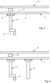
Figur 3 ist der Lochplatte 1 zusätzlich eine Fixierplatte 8 zugeordnet, wobei ein Abstand a zwischen Lochplatte 1 und Fixierplatte 8 veränderbar ist. Diese Fixierplatte 8 hat u.a. die Aufgabe, nach der Einstellung der einzelnen Prüfstifte 2, diese gegenüber der Lochplatte 1 festzulegen, d.h., sie unterstützt im wesentlichen den Magnet 6, damit die Prüfstifte 2 beim Absenken auf die Leiterplatte 3 nicht von der Lochplatte 1 abgehoben werden und die Lage der Prüfstifte 2 versehentlich verändert wird. - In der Vorrichtung zum Prüfen von Werkstücken gemäss
Figur 3 wird als Halterung 1.1 nicht eine Lochplatte sondern eine halbmagnetische Platte verwendet. Das bedeutet, dass die grundsätzliche Position der Prüfstifte 2.1 in diesem Fall nicht vom Lochraster einer Lochplatte abhängt, sondern der Prüfstift 2.1 frei entlang einer Unterseite 9 der Halterung 1.1 bewegt werden kann. - Eine Drehung des Prüfstiftes 2.1 um seine Achse A wird durch einen Antriebsmagnet 10 bewirkt, der jenseits vom Prüfstift 2.1 der Halterung 1.1 zugeordnet ist. Dieser Antriebsmagnet 10 kann entlang der Halterung 1.1 in beliebiger Richtung bewegt, aber auch gedreht werden, so dass ihm der Magnet 6 folgt und so eine Ausrichtung des Prüfstifts 2.1 gegenüber einer nicht gezeigten Leiterplatte erfolgen kann.
- Oberhalb des Antriebsmagnets 10 ist noch eine magnetisch leitende Fixierplatte 8.1 vorgesehen, mit der die gesamte Anordnung festgelegt werden kann.
- Die Vorrichtung zum Prüfen eines Werkstücks gemäss
Figur 4 unterscheidet sich von derjenigen nachFigur 3 nur durch die Anordnung eines zusätzlichen Werkzeugs 11, mit dem eine weitere Tätigkeit vorgenommen werden kann. Beispielsweise kann es sich dabei um einen gefederten Niederhalter handeln, der auf das Werkstück drückt oder aber auch um eine Kamera, welche die Prüfspitze 5 beobachtet. - Bei der Vorrichtung zum Prüfen eines Werkstücks 3 gemäss
Figur 5 befindet sich der Prüfstift 2.2 an einem Schlitten 11, der in beliebiger Weise bewegt werden kann. Nur beispielsweise wird hier wiederum auf dieDE 10 2012 106 291.9 verwiesen. Die Bewegung des Schlittens 11 bzw. die Lage des Prüfstifts 2.2 gegenüber der Leiterplatte 3 kann durch eine separate Kamera 12 und/oder auch durch eine dem Schlitten 11 zugeordnete Kamera 13 beobachtet und kontrolliert werden. - In
Figur 6 ist angedeutet, dass die Tätigkeit des Prüfstifts 2 durch zwei schräggestellte Kameras 12.1 und 12.2 beobachtet wird. - In
Figur 7 durchsetzt der Prüfstift 2 bzw. eine Prüfspitze 5 das Objektiv 14 einer Kamera direkt, so dass dieses Objektiv 14 direkt auf einen Auftreffpunkt 15 der Prüfspitze 5 auf der Leiterplatte 3 ausgerichtet ist. - Eine Ausführungsform der vorliegenden Erfindung wird in den
Figuren 8 bis 13 aufgezeigt. Dabei handelt es sich um die Möglichkeit der Bewegung eines Prüfstiftes 2 mittels elektroaktiver Polymere 16, die als Aktuatoren für den Prüfstift 2 wirken. - In den
Figuren 9 bis 13 wird eine weitere Möglichkeit der Bewegung der Prüfstifte 2 aufgezeigt, die durch sogenannte intrinsisch aktive Polymere bewirkt wird. Sie bewegen sich muskelähnlich. Für den vorliegenden Erfindungsgedanken werden vor allem elektroaktive Polymere (EAP) bevorzugt, da mittels einer elektrischen Feldgrösse das Polymer direkt und gezielt beeinflusst werden kann. - Gemäss
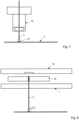
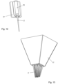
Figur 9 wird ein entsprechender Prüfstift 2 in einer Lochplatte 1 geführt. Auf bzw. über der Lochplatte 1 befinden EAP-Aktuatoren 16.1 und 16.2, welche den Prüfstift 2 angreifen. Schematisch ist dies vor allem in denFiguren 10 und 11 dargestellt. Der entsprechende EAP-Aktuator umgibt den Prüfstift 2, wobei der EAP-Aktuator 16 selbst gemässFigur 10 von vier Seiten her mit einer elektrischen Feldgrösse beaufschlagt wird. Diese bewirkt beispielsweise gemässFigur 11 , dass sich ein mittlerer Bereich des EAP-Aktuators aufwölbt und dabei den Prüfstift 2 anhebt. Durch entsprechende Beaufschlagung des EAP-Aktuators mit der elektrischen Feldgrösse kann auch eine Drehung des Prüfstifts 2 bewirkt werden. - In den
Figuren 12 und 13 ist dargestellt, wie ein entsprechender Prüfstift 2 in ein Gehäuse 17 integriert ist, wobei der Prüfstift 2 im oberen Bereich bzw. innerhalb des Gehäuses 17 von einem EAP-Aktuator 16 umgeben ist. - Dabei ragen aus dem Gehäuse 17 eine Mehrzahl von Prüfstiften 2 heraus. Diese Kontaktnadeln oder Prüfstifte 2 sind von einem Polymerreaktor 16 umfangen, der in das Gehäuse 17 eingebettet ist.
- Dieser hydrogelbasierte Aktor besitzt die Aufgabe, die Kontaktnadel mit einer Positioniergenauigkeit von ca. 25 µm frei in der x-y-Ebene bei maximalen Positionierwegen von +/- 500 µm ausgehend von der Normalposition zu stellen. Diese komplizierte mehraxiale Positionierung lässt sich mit einem flexiblen Festkörperreaktor realisieren, der sich bei entsprechender Ansteuerung in analoger Weise so deformiert, dass er über die Kontaktnadel jeden beliebigen Punkt in der Positionierebene anfahren kann. Dies erfordert das Finden einer geeigneten konstruktiven Gestaltung und Dimensionierung. Die erreichbare Positioniergenauigkeit wird darüber hinaus von der Leistungsfähigkeit der Aktor-Steuerelektroden bestimmt. Die resistiven Steuerelektroden sind segmentiert und realisieren ein Steuern des Temperaturfelds, welches elektronisch um 360° drehbar ist. Wesentliche Untersuchungskriterien sind die notwendige Elektrodenanzahl, um die Kontaktnadeln hinreichend genau positionieren zu können, die benötigte Heizleistung, der Verlauf des Wärmefeldes, die Wärmeeinkopplung und das Wärmemanagement zum Stabilisieren des steuernden Temperaturfeldes.
- Der Kontaktnadel-Positionierantrieb ist nur für den eigentlichen Positioniervorgang zuständig. Sollte die Kontaktnadel ihre Endposition erreicht haben, wird ein Arretiermechanismus aktiviert, welcher die Nadeln in ihrer Position fixieren.
- Während der Nadelpositionierung ist sicherzustellen, dass der Kopf im Bereich der Positionierantriebe eine gleichbleibende, definierte Temperatur aufweist, um die Unabhängigkeit der Positioniervorgänge von eventuellen Schwankungen der Umgebungstemperatur zu gewährleisten. Das aktive Temperaturmanagement lässt sich z.B. durch Peltierelemente oder eine aktive Wasserkühlung realisieren.
- Das Antriebsgehäuse sorgt nicht nur für den mechanischen Schutz des Positionierantriebs, sondern trägt auch dessen mechanische und elektrische Schnittstellen.
- Der Kopf muss zudem über Justagemöglichkeiten verfügen, um ihn optimal einstellen bzw. vorpositionieren zu können. Für die Positionierantriebe lässt sich im Idealfall eine globale Justage realisieren, alternativ werden Konzepte der Einzeljustage untersucht.
- Für den Arretiermechanismus scheinen vor allem kraftschlüssige Prinzipien geeignet.
-
1 Halterung 34 67 2 Prüfstift 35 68 3 Leiterplatte 36 69 4 Schaft 37 70 5 Prüfspitze 38 71 6 Magnet 39 72 7 Hilfsvierkant 40 73 8 Fixierplatte 41 74 9 Unterseite 42 75 10 Antriebsmagnet 43 76 11 Schlitten 44 77 12 Kamera 45 78 13 Kamera 46 79 14 Objektiv 47 15 Auftreffpunkt 48 16 EAP-Aktuator 49 17 Gehäuse 50 18 PCB-Platte 51 19 Werkzeug 52 A Achse 20 53 21 54 a Abstand 22 55 23 56 24 57 25 58 26 59 27 60 28 61 29 62 30 63 31 64 32 65 33 66
Claims (9)
- Verfahren zum Prüfen eines Werkstücks (3), insbesondere einer Leiterplatte, mittels einem mit einem Schaft (4) eine Halterung (1) durchsetzenden Prüfstift (2), der eine vorbestimmte Position auf oder in dem Werkstück (3) anfährt, wobei eine Lage des Prüfstifts (2) gegenüber der Halterung (1) verändert wird,
dadurch gekennzeichnet,
dass eine Veränderung der Lage des Prüfstifts (2) gegenüber der Halterung (1) durch ein intrinsisch aktives Polymer erfolgt, das den Schaft (4) des Prüfstifts (2) zumindest teilweise umfängt, wobei die intrinsisch aktiven Polymere im Siebdruckverfahren auf die Halterung (1) aufgebracht werden. - Verfahren nach Anspruch 1, dadurch gekennzeichnet, dass die Veränderung der Lage des Prüfstifts (2) beobachtet wird.
- Verfahren nach Anspruch 2, dadurch gekennzeichnet, dass die Veränderung der Lage des Prüfstifts (2) dadurch beobachtet wird, dass der Prüfstift (2) durch das Objektiv (14) einer Kamera geführt wird.
- Vorrichtung zum Prüfen eines Werkstücks (3), insbesondere einer Leiterplatte, mittels einem mit einem Schaft (4) eine Halterung (1) durchsetzenden Prüfstift (2), der eine vorbestimmte Position auf oder in dem Werkstück (3) anfährt, wobei eine Lage des Prüfstifts (2) gegenüber der Halterung (1) veränderbar ist, dadurch gekennzeichnet, dass dem Prüfstift (2) ein intrinsisch aktives Polymer (16) zugeordnet ist, das dazu ausgebildet ist, die Lage des Prüfstifts (2) gegenüber der Halterung (1) zu verändern, und welches den Schaft (4) des Prüfstifts (2) zumindest teilweise umfängt, wobei das intrinsisch aktive Polymere (16) im Siebdruckverfahren auf die Halterung (1) aufgebracht ist.
- Vorrichtung nach Anspruch 4, dadurch gekennzeichnet, dass das intrinsisch aktive Polymer (16) ein elektroaktives Polymer ist.
- Vorrichtung nach Anspruch 5, dadurch gekennzeichnet, dass das Polymer von vier Seiten her mit einer elektrischen Feldgröße beaufschlagt wird.
- Vorrichtung nach Anspruch 4, dadurch gekennzeichnet, dass das Polymer (16) ein stimuli-sensitives Hydrogel ist.
- Vorrichtung nach Anspruch 7, dadurch gekennzeichnet, dass das intrinsisch aktive Polymer (16) ein temperatursensitives Poly(N-Isopropylacrylamid) (PNIPAAm) ist.
- Verwendung von einem intrinsisch aktiven Polymer (16) zur Bewegung von Prüfstiften (2), die mit einem Schaft (4) eine Halterung (1) durchsetzen und der Prüfung von Werkstücken (3), insbesondere von Leiterplatten dienen, wobei die Prüfstifte (2) eine vorbestimmte Position auf oder in dem Werkstück (3) anfahren, wobei eine Veränderung der Lage jedes Prüfstifts (2) gegenüber der Halterung (1) durch das intrinsisch aktives Polymer erfolgt, wobei das intrinsisch aktive Polymer (16) den Schaft (4) des Prüfstifts (2) zumindest teilweise umfängt, wobei das intrinsisch aktive Polymere (16) im Siebdruckverfahren auf die Halterung (1) aufgebracht ist.
Applications Claiming Priority (3)
| Application Number | Priority Date | Filing Date | Title |
|---|---|---|---|
| DE201210111215 DE102012111215A1 (de) | 2012-11-21 | 2012-11-21 | Verfahren und Vorrichtung zum Prüfen eines Werkstücks |
| DE201210111216 DE102012111216A1 (de) | 2012-11-21 | 2012-11-21 | Verfahren zum Bewegen eines Gegenstandes |
| PCT/EP2013/074348 WO2014079913A1 (de) | 2012-11-21 | 2013-11-21 | Verfahren und vorrichtung zum prüfen eines werkstücks |
Publications (2)
| Publication Number | Publication Date |
|---|---|
| EP2923211A1 EP2923211A1 (de) | 2015-09-30 |
| EP2923211B1 true EP2923211B1 (de) | 2025-03-19 |
Family
ID=49841633
Family Applications (1)
| Application Number | Title | Priority Date | Filing Date |
|---|---|---|---|
| EP13811135.6A Active EP2923211B1 (de) | 2012-11-21 | 2013-11-21 | Verfahren und vorrichtung zum prüfen eines werkstücks |
Country Status (4)
| Country | Link |
|---|---|
| US (1) | US9739826B2 (de) |
| EP (1) | EP2923211B1 (de) |
| CN (2) | CN104969080B (de) |
| WO (1) | WO2014079913A1 (de) |
Families Citing this family (3)
| Publication number | Priority date | Publication date | Assignee | Title |
|---|---|---|---|---|
| CN106093752B (zh) * | 2016-06-20 | 2019-03-12 | 定颖电子(黄石)有限公司 | 一种应用于集成电路的测试探针卡 |
| DE102016123122B3 (de) * | 2016-11-30 | 2018-03-15 | Michael Konrad | Haptic-Test-Messvorrichtung und Verfahren zur Ermittlung einer Kraft-Weg-Kurve bei einer Haptic-Test-Messung |
| CN113484722B (zh) * | 2021-07-06 | 2022-07-08 | 广州弘高科技股份有限公司 | 一种手机pcb板的测试装置及测试方法 |
Citations (2)
| Publication number | Priority date | Publication date | Assignee | Title |
|---|---|---|---|---|
| WO2008113372A2 (en) * | 2007-03-16 | 2008-09-25 | Micromuscle Ab | Electroactive polymer actuator devices and systems comprising such devices |
| WO2012075033A2 (en) * | 2010-11-29 | 2012-06-07 | President And Fellows Of Harvard College | Environmentally responsive optical microstructured hybrid actuator assemblies and applications thereof |
Family Cites Families (37)
| Publication number | Priority date | Publication date | Assignee | Title |
|---|---|---|---|---|
| US3851249A (en) * | 1973-06-04 | 1974-11-26 | Electroglass Inc | Microcircuit test device with multi-axes probe control and probe stop means |
| DE2628428C3 (de) | 1976-06-24 | 1979-02-15 | Siemens Ag, 1000 Berlin Und 8000 Muenchen | Adapter zum Verbinden von Anschluß- und/oder Prüfpunkten einer Baugruppe mit einer Mefischaltung |
| DE2800775A1 (de) | 1978-01-09 | 1979-07-12 | Luther & Maelzer Gmbh | Verfahrensanordnung und vorrichtung zur aufnahme und funktionsmessueberpruefung von unbestueckten leiterplatten |
| FR2418466A1 (fr) * | 1978-02-24 | 1979-09-21 | Telecommunications Sa | Appareil pour etablir des prises de contact temporaires sur des circuits electriques |
| US4527119A (en) * | 1982-05-17 | 1985-07-02 | Testamatic, Incorporated | High speed, low mass, movable probe and/or instrument positioner, tool and like items suitable for use in a controlled environment chamber |
| US4884024A (en) * | 1985-11-19 | 1989-11-28 | Teradyne, Inc. | Test pin assembly for circuit board tester |
| US5345170A (en) * | 1992-06-11 | 1994-09-06 | Cascade Microtech, Inc. | Wafer probe station having integrated guarding, Kelvin connection and shielding systems |
| US5502397A (en) * | 1992-11-12 | 1996-03-26 | Advanced Micro Devices, Inc. | Integrated circuit testing apparatus and method |
| US5255979A (en) * | 1993-02-01 | 1993-10-26 | Ferrari R Keith | Medical temperature probe cover |
| US5394100A (en) * | 1993-05-06 | 1995-02-28 | Karl Suss America, Incorporated | Probe system with automatic control of contact pressure and probe alignment |
| DE4416151C1 (de) | 1994-05-09 | 1995-07-27 | Ingun Pruefmittelbau | Vorrichtung zum Kontaktieren von Prüfpunkten einer elektronischen Leiterplatte o. dgl. Prüfling |
| DE19503329C2 (de) * | 1995-02-02 | 2000-05-18 | Ita Ingb Testaufgaben Gmbh | Testvorrichtung für elektronische Flachbaugruppen |
| US5532611A (en) | 1995-05-26 | 1996-07-02 | International Business Machines Corporation | Miniature probe positioning actuator |
| US5867032A (en) * | 1995-11-30 | 1999-02-02 | Motorola, Inc. | Process for testing a semiconductor device |
| KR0176627B1 (ko) * | 1995-12-30 | 1999-05-15 | 김광호 | 인쇄회로기판의 통전검사용 프로브 장치 |
| US6051982A (en) | 1996-08-02 | 2000-04-18 | International Business Machines Corporation | Electronic component test apparatus with rotational probe and conductive spaced apart means |
| DE19646252A1 (de) | 1996-11-08 | 1998-05-14 | Ingun Pruefmittelbau | Prüfvorrichtung |
| US6664718B2 (en) * | 2000-02-09 | 2003-12-16 | Sri International | Monolithic electroactive polymers |
| AU2001272733A1 (en) * | 2000-07-19 | 2002-02-05 | Orbotech Ltd. | Apparatus and method for electrical testing of electrical circuits |
| US7202690B2 (en) * | 2001-02-19 | 2007-04-10 | Nidec-Read Corporation | Substrate inspection device and substrate inspecting method |
| DE10160119A1 (de) * | 2001-12-07 | 2003-10-02 | Atg Test Systems Gmbh | Prüfsonde für einen Fingertester |
| DE10220343B4 (de) * | 2002-05-07 | 2007-04-05 | Atg Test Systems Gmbh & Co. Kg Reicholzheim | Vorrichtung und Verfahren zum Prüfen von Leiterplatten und Prüfsonde |
| CN1696710A (zh) * | 2004-05-15 | 2005-11-16 | 鸿富锦精密工业(深圳)有限公司 | 检测装置 |
| JP2008533441A (ja) * | 2005-02-08 | 2008-08-21 | ナノネクサス インク | Icパッケージおよび相互接続アゼンブリのための高密度の相互接続システム |
| US7091730B1 (en) * | 2005-07-15 | 2006-08-15 | Huntron, Inc. | Dual probe assembly for a printed circuit board test apparatus |
| WO2007057944A1 (ja) | 2005-11-15 | 2007-05-24 | Advantest Corporation | 電子部品試験装置及び電子部品試験装置へのパフォーマンスボードの装着方法 |
| KR20080078681A (ko) * | 2005-12-20 | 2008-08-27 | 코닌클리케 필립스 일렉트로닉스 엔.브이. | 유전성 폴리머 액추에이터를 사용하는 카메라 조리개 및렌즈 위치지정 시스템 |
| JP2007303826A (ja) * | 2006-05-08 | 2007-11-22 | Tokyo Electron Ltd | プローブ |
| TWI305828B (en) * | 2006-12-28 | 2009-02-01 | Ind Tech Res Inst | Phase-sensitive probing apparatus |
| US8870144B2 (en) * | 2007-05-04 | 2014-10-28 | GM Global Technology Operations LLC | Active material adaptive object holders |
| JPWO2009107558A1 (ja) * | 2008-02-26 | 2011-06-30 | 電気化学工業株式会社 | プローブの検査方法及び硬化性樹脂組成物 |
| KR20090117097A (ko) | 2008-05-08 | 2009-11-12 | 삼성전자주식회사 | 재배선 탐침 구조물을 갖는 프로브 카드 및 이를 이용하는프로브 카드 모듈 |
| US7898266B2 (en) * | 2008-06-04 | 2011-03-01 | Seagate Technology Llc | Probe with electrostatic actuation and capacitive sensor |
| US8011931B2 (en) * | 2008-10-14 | 2011-09-06 | Cheng Uei Precision Industry Co., Ltd. | Probe connector |
| US8222799B2 (en) * | 2008-11-05 | 2012-07-17 | Bayer Materialscience Ag | Surface deformation electroactive polymer transducers |
| US8390305B2 (en) * | 2009-05-08 | 2013-03-05 | GM Global Technology Operations LLC | Methods of determining mid-stroke positions of active material actuated loads |
| US8297421B2 (en) * | 2009-11-17 | 2012-10-30 | GM Global Technology Operations LLC | Active materials actuated one-way clutch |
-
2013
- 2013-11-21 CN CN201380068866.XA patent/CN104969080B/zh active Active
- 2013-11-21 EP EP13811135.6A patent/EP2923211B1/de active Active
- 2013-11-21 US US14/646,424 patent/US9739826B2/en active Active
- 2013-11-21 WO PCT/EP2013/074348 patent/WO2014079913A1/de not_active Ceased
- 2013-11-21 CN CN201910032760.3A patent/CN110031658B/zh active Active
Patent Citations (2)
| Publication number | Priority date | Publication date | Assignee | Title |
|---|---|---|---|---|
| WO2008113372A2 (en) * | 2007-03-16 | 2008-09-25 | Micromuscle Ab | Electroactive polymer actuator devices and systems comprising such devices |
| WO2012075033A2 (en) * | 2010-11-29 | 2012-06-07 | President And Fellows Of Harvard College | Environmentally responsive optical microstructured hybrid actuator assemblies and applications thereof |
Also Published As
| Publication number | Publication date |
|---|---|
| CN110031658B (zh) | 2021-11-30 |
| CN104969080B (zh) | 2019-02-15 |
| CN110031658A (zh) | 2019-07-19 |
| CN104969080A (zh) | 2015-10-07 |
| HK1211088A1 (en) | 2016-05-13 |
| US20160011253A1 (en) | 2016-01-14 |
| US9739826B2 (en) | 2017-08-22 |
| EP2923211A1 (de) | 2015-09-30 |
| WO2014079913A1 (de) | 2014-05-30 |
Similar Documents
| Publication | Publication Date | Title |
|---|---|---|
| DE102005032520B4 (de) | Konfigurierbarer Prober zum Testen eines TFT LCD Arrays | |
| DE102010025760A1 (de) | Vorrichtung zum Testen einer integrierten Schaltung | |
| EP3332261A1 (de) | Positioniereinrichtung für einen paralleltester zum testen von leiterplatten und paralleltester zum testen von leiterplatten | |
| DE102008038184A1 (de) | Verfahren und Vorrichtung zur temporären elektrischen Kontaktierung einer Solarzelle | |
| DE2559004C2 (de) | Anordnung zur Prüfung von elektrischen Prüflingen mit einer Vielzahl von Prüfkontakten | |
| EP2923211B1 (de) | Verfahren und vorrichtung zum prüfen eines werkstücks | |
| DE102008009017B4 (de) | Verfahren zur Messung eines Halbleitersubstrats | |
| EP0831332B1 (de) | Adapter zum Prüfen von elektrischen Leiterplatten | |
| EP0315707B1 (de) | Adapter für eine Vorrichtung zur elektronischen Prüfung von Leiterplatten | |
| EP0222345B1 (de) | Verfahren zur Prüfung einer Leiterplatte | |
| DE60217619T2 (de) | Vorrichtung zur Abtastprüfung von Leiterplatten | |
| DE60115272T2 (de) | Abtaster für genaue bewegung und niedrige leistungsaufnahme | |
| DE10010392B4 (de) | Piezoelekronisches X-Y-Mikropositioniersystem | |
| DE112022004532T5 (de) | Robotervorrichtung und steuerverfahren dafür | |
| DE102008043543A1 (de) | Siebdruckvorrichtung | |
| WO2014108464A1 (de) | Mechanische schnittstelle, modulsystem und maschine | |
| EP1793231A2 (de) | Elektrische Prüfvorrichtung für die Prüfung eines elektrischen Prüflings sowie entsprechendes Verfahren | |
| DE102007060796A1 (de) | Halterung für eine Mikropipette | |
| DE102012111215A1 (de) | Verfahren und Vorrichtung zum Prüfen eines Werkstücks | |
| EP1954115B1 (de) | Mehrfach-Bestückkopf mit kollektivem Drehantrieb und verfahrbarem Hubantrieb für Bauelement-Halteeinrichtungen | |
| WO2010031685A1 (de) | Verfahren zur prüfung elektronischer bauelemente einer wiederholstruktur unter definierten thermischen bedingungen | |
| EP3847466A1 (de) | Verfahren zur positionierung von testsubstrat, sonden und inspektionseinheit relativ zueinander und prober zu dessen ausführung | |
| DE69626527T2 (de) | Verfahren zur kontrolle von leiterplatten | |
| WO2004021757A1 (de) | Vorrichtung zum selektiven bewegen von haltevorrichtungen und bestückkopf zum transportieren von bauelementen | |
| DE102012111216A1 (de) | Verfahren zum Bewegen eines Gegenstandes |
Legal Events
| Date | Code | Title | Description |
|---|---|---|---|
| PUAI | Public reference made under article 153(3) epc to a published international application that has entered the european phase |
Free format text: ORIGINAL CODE: 0009012 |
|
| 17P | Request for examination filed |
Effective date: 20150622 |
|
| AK | Designated contracting states |
Kind code of ref document: A1 Designated state(s): AL AT BE BG CH CY CZ DE DK EE ES FI FR GB GR HR HU IE IS IT LI LT LU LV MC MK MT NL NO PL PT RO RS SE SI SK SM TR |
|
| AX | Request for extension of the european patent |
Extension state: BA ME |
|
| DAX | Request for extension of the european patent (deleted) | ||
| STAA | Information on the status of an ep patent application or granted ep patent |
Free format text: STATUS: EXAMINATION IS IN PROGRESS |
|
| 17Q | First examination report despatched |
Effective date: 20180405 |
|
| GRAP | Despatch of communication of intention to grant a patent |
Free format text: ORIGINAL CODE: EPIDOSNIGR1 |
|
| STAA | Information on the status of an ep patent application or granted ep patent |
Free format text: STATUS: GRANT OF PATENT IS INTENDED |
|
| INTG | Intention to grant announced |
Effective date: 20241016 |
|
| GRAS | Grant fee paid |
Free format text: ORIGINAL CODE: EPIDOSNIGR3 |
|
| GRAA | (expected) grant |
Free format text: ORIGINAL CODE: 0009210 |
|
| STAA | Information on the status of an ep patent application or granted ep patent |
Free format text: STATUS: THE PATENT HAS BEEN GRANTED |
|
| AK | Designated contracting states |
Kind code of ref document: B1 Designated state(s): AL AT BE BG CH CY CZ DE DK EE ES FI FR GB GR HR HU IE IS IT LI LT LU LV MC MK MT NL NO PL PT RO RS SE SI SK SM TR |
|
| REG | Reference to a national code |
Ref country code: GB Ref legal event code: FG4D Free format text: NOT ENGLISH |
|
| REG | Reference to a national code |
Ref country code: CH Ref legal event code: EP |
|
| REG | Reference to a national code |
Ref country code: DE Ref legal event code: R096 Ref document number: 502013016578 Country of ref document: DE |
|
| REG | Reference to a national code |
Ref country code: IE Ref legal event code: FG4D Free format text: LANGUAGE OF EP DOCUMENT: GERMAN |
|
| PG25 | Lapsed in a contracting state [announced via postgrant information from national office to epo] |
Ref country code: RS Free format text: LAPSE BECAUSE OF FAILURE TO SUBMIT A TRANSLATION OF THE DESCRIPTION OR TO PAY THE FEE WITHIN THE PRESCRIBED TIME-LIMIT Effective date: 20250619 |
|
| PG25 | Lapsed in a contracting state [announced via postgrant information from national office to epo] |
Ref country code: FI Free format text: LAPSE BECAUSE OF FAILURE TO SUBMIT A TRANSLATION OF THE DESCRIPTION OR TO PAY THE FEE WITHIN THE PRESCRIBED TIME-LIMIT Effective date: 20250319 |
|
| REG | Reference to a national code |
Ref country code: LT Ref legal event code: MG9D |
|
| PG25 | Lapsed in a contracting state [announced via postgrant information from national office to epo] |
Ref country code: NO Free format text: LAPSE BECAUSE OF FAILURE TO SUBMIT A TRANSLATION OF THE DESCRIPTION OR TO PAY THE FEE WITHIN THE PRESCRIBED TIME-LIMIT Effective date: 20250619 |
|
| PG25 | Lapsed in a contracting state [announced via postgrant information from national office to epo] |
Ref country code: HR Free format text: LAPSE BECAUSE OF FAILURE TO SUBMIT A TRANSLATION OF THE DESCRIPTION OR TO PAY THE FEE WITHIN THE PRESCRIBED TIME-LIMIT Effective date: 20250319 |
|
| PG25 | Lapsed in a contracting state [announced via postgrant information from national office to epo] |
Ref country code: LV Free format text: LAPSE BECAUSE OF FAILURE TO SUBMIT A TRANSLATION OF THE DESCRIPTION OR TO PAY THE FEE WITHIN THE PRESCRIBED TIME-LIMIT Effective date: 20250319 |
|
| PG25 | Lapsed in a contracting state [announced via postgrant information from national office to epo] |
Ref country code: GR Free format text: LAPSE BECAUSE OF FAILURE TO SUBMIT A TRANSLATION OF THE DESCRIPTION OR TO PAY THE FEE WITHIN THE PRESCRIBED TIME-LIMIT Effective date: 20250620 Ref country code: BG Free format text: LAPSE BECAUSE OF FAILURE TO SUBMIT A TRANSLATION OF THE DESCRIPTION OR TO PAY THE FEE WITHIN THE PRESCRIBED TIME-LIMIT Effective date: 20250319 |
|
| REG | Reference to a national code |
Ref country code: NL Ref legal event code: MP Effective date: 20250319 |
|
| PG25 | Lapsed in a contracting state [announced via postgrant information from national office to epo] |
Ref country code: NL Free format text: LAPSE BECAUSE OF FAILURE TO SUBMIT A TRANSLATION OF THE DESCRIPTION OR TO PAY THE FEE WITHIN THE PRESCRIBED TIME-LIMIT Effective date: 20250319 |
|
| PG25 | Lapsed in a contracting state [announced via postgrant information from national office to epo] |
Ref country code: SE Free format text: LAPSE BECAUSE OF FAILURE TO SUBMIT A TRANSLATION OF THE DESCRIPTION OR TO PAY THE FEE WITHIN THE PRESCRIBED TIME-LIMIT Effective date: 20250319 |
|
| PG25 | Lapsed in a contracting state [announced via postgrant information from national office to epo] |
Ref country code: SM Free format text: LAPSE BECAUSE OF FAILURE TO SUBMIT A TRANSLATION OF THE DESCRIPTION OR TO PAY THE FEE WITHIN THE PRESCRIBED TIME-LIMIT Effective date: 20250319 |
|
| PG25 | Lapsed in a contracting state [announced via postgrant information from national office to epo] |
Ref country code: ES Free format text: LAPSE BECAUSE OF FAILURE TO SUBMIT A TRANSLATION OF THE DESCRIPTION OR TO PAY THE FEE WITHIN THE PRESCRIBED TIME-LIMIT Effective date: 20250319 Ref country code: PT Free format text: LAPSE BECAUSE OF FAILURE TO SUBMIT A TRANSLATION OF THE DESCRIPTION OR TO PAY THE FEE WITHIN THE PRESCRIBED TIME-LIMIT Effective date: 20250721 |
|
| PG25 | Lapsed in a contracting state [announced via postgrant information from national office to epo] |
Ref country code: IT Free format text: LAPSE BECAUSE OF FAILURE TO SUBMIT A TRANSLATION OF THE DESCRIPTION OR TO PAY THE FEE WITHIN THE PRESCRIBED TIME-LIMIT Effective date: 20250319 Ref country code: PL Free format text: LAPSE BECAUSE OF FAILURE TO SUBMIT A TRANSLATION OF THE DESCRIPTION OR TO PAY THE FEE WITHIN THE PRESCRIBED TIME-LIMIT Effective date: 20250319 |
|
| PG25 | Lapsed in a contracting state [announced via postgrant information from national office to epo] |
Ref country code: EE Free format text: LAPSE BECAUSE OF FAILURE TO SUBMIT A TRANSLATION OF THE DESCRIPTION OR TO PAY THE FEE WITHIN THE PRESCRIBED TIME-LIMIT Effective date: 20250319 Ref country code: CZ Free format text: LAPSE BECAUSE OF FAILURE TO SUBMIT A TRANSLATION OF THE DESCRIPTION OR TO PAY THE FEE WITHIN THE PRESCRIBED TIME-LIMIT Effective date: 20250319 |
|
| PG25 | Lapsed in a contracting state [announced via postgrant information from national office to epo] |
Ref country code: RO Free format text: LAPSE BECAUSE OF FAILURE TO SUBMIT A TRANSLATION OF THE DESCRIPTION OR TO PAY THE FEE WITHIN THE PRESCRIBED TIME-LIMIT Effective date: 20250319 |
|
| PG25 | Lapsed in a contracting state [announced via postgrant information from national office to epo] |
Ref country code: SK Free format text: LAPSE BECAUSE OF FAILURE TO SUBMIT A TRANSLATION OF THE DESCRIPTION OR TO PAY THE FEE WITHIN THE PRESCRIBED TIME-LIMIT Effective date: 20250319 |
|
| PG25 | Lapsed in a contracting state [announced via postgrant information from national office to epo] |
Ref country code: IS Free format text: LAPSE BECAUSE OF FAILURE TO SUBMIT A TRANSLATION OF THE DESCRIPTION OR TO PAY THE FEE WITHIN THE PRESCRIBED TIME-LIMIT Effective date: 20250719 |
|
| REG | Reference to a national code |
Ref country code: DE Ref legal event code: R097 Ref document number: 502013016578 Country of ref document: DE |
|
| PG25 | Lapsed in a contracting state [announced via postgrant information from national office to epo] |
Ref country code: DK Free format text: LAPSE BECAUSE OF FAILURE TO SUBMIT A TRANSLATION OF THE DESCRIPTION OR TO PAY THE FEE WITHIN THE PRESCRIBED TIME-LIMIT Effective date: 20250319 |
|
| PLBE | No opposition filed within time limit |
Free format text: ORIGINAL CODE: 0009261 |
|
| STAA | Information on the status of an ep patent application or granted ep patent |
Free format text: STATUS: NO OPPOSITION FILED WITHIN TIME LIMIT |
|
| REG | Reference to a national code |
Ref country code: CH Ref legal event code: L10 Free format text: ST27 STATUS EVENT CODE: U-0-0-L10-L00 (AS PROVIDED BY THE NATIONAL OFFICE) Effective date: 20260128 |
|
| 26N | No opposition filed |
Effective date: 20251222 |
|
| PGFP | Annual fee paid to national office [announced via postgrant information from national office to epo] |
Ref country code: DE Payment date: 20260127 Year of fee payment: 13 |