EP2923081B1 - Vertical axis turbine - Google Patents
Vertical axis turbine Download PDFInfo
- Publication number
- EP2923081B1 EP2923081B1 EP13814443.1A EP13814443A EP2923081B1 EP 2923081 B1 EP2923081 B1 EP 2923081B1 EP 13814443 A EP13814443 A EP 13814443A EP 2923081 B1 EP2923081 B1 EP 2923081B1
- Authority
- EP
- European Patent Office
- Prior art keywords
- pitch
- camber
- turbine
- blade portion
- pivot
- Prior art date
- Legal status (The legal status is an assumption and is not a legal conclusion. Google has not performed a legal analysis and makes no representation as to the accuracy of the status listed.)
- Active
Links
- 230000007246 mechanism Effects 0.000 claims description 19
- 239000012530 fluid Substances 0.000 claims description 6
- 230000037361 pathway Effects 0.000 claims 2
- 238000010276 construction Methods 0.000 description 8
- XLYOFNOQVPJJNP-UHFFFAOYSA-N water Substances O XLYOFNOQVPJJNP-UHFFFAOYSA-N 0.000 description 6
- 230000001788 irregular Effects 0.000 description 5
- 230000003252 repetitive effect Effects 0.000 description 2
- 230000001419 dependent effect Effects 0.000 description 1
- 230000000694 effects Effects 0.000 description 1
- 230000008676 import Effects 0.000 description 1
- 230000003993 interaction Effects 0.000 description 1
- 238000012423 maintenance Methods 0.000 description 1
Images


Classifications
-
- F—MECHANICAL ENGINEERING; LIGHTING; HEATING; WEAPONS; BLASTING
- F03—MACHINES OR ENGINES FOR LIQUIDS; WIND, SPRING, OR WEIGHT MOTORS; PRODUCING MECHANICAL POWER OR A REACTIVE PROPULSIVE THRUST, NOT OTHERWISE PROVIDED FOR
- F03D—WIND MOTORS
- F03D3/00—Wind motors with rotation axis substantially perpendicular to the air flow entering the rotor
- F03D3/06—Rotors
- F03D3/062—Rotors characterised by their construction elements
- F03D3/066—Rotors characterised by their construction elements the wind engaging parts being movable relative to the rotor
- F03D3/067—Cyclic movements
- F03D3/068—Cyclic movements mechanically controlled by the rotor structure
-
- F—MECHANICAL ENGINEERING; LIGHTING; HEATING; WEAPONS; BLASTING
- F03—MACHINES OR ENGINES FOR LIQUIDS; WIND, SPRING, OR WEIGHT MOTORS; PRODUCING MECHANICAL POWER OR A REACTIVE PROPULSIVE THRUST, NOT OTHERWISE PROVIDED FOR
- F03B—MACHINES OR ENGINES FOR LIQUIDS
- F03B3/00—Machines or engines of reaction type; Parts or details peculiar thereto
- F03B3/12—Blades; Blade-carrying rotors
- F03B3/14—Rotors having adjustable blades
- F03B3/145—Mechanisms for adjusting the blades
-
- F—MECHANICAL ENGINEERING; LIGHTING; HEATING; WEAPONS; BLASTING
- F03—MACHINES OR ENGINES FOR LIQUIDS; WIND, SPRING, OR WEIGHT MOTORS; PRODUCING MECHANICAL POWER OR A REACTIVE PROPULSIVE THRUST, NOT OTHERWISE PROVIDED FOR
- F03D—WIND MOTORS
- F03D7/00—Controlling wind motors
- F03D7/06—Controlling wind motors the wind motors having rotation axis substantially perpendicular to the air flow entering the rotor
-
- F—MECHANICAL ENGINEERING; LIGHTING; HEATING; WEAPONS; BLASTING
- F05—INDEXING SCHEMES RELATING TO ENGINES OR PUMPS IN VARIOUS SUBCLASSES OF CLASSES F01-F04
- F05B—INDEXING SCHEME RELATING TO WIND, SPRING, WEIGHT, INERTIA OR LIKE MOTORS, TO MACHINES OR ENGINES FOR LIQUIDS COVERED BY SUBCLASSES F03B, F03D AND F03G
- F05B2260/00—Function
- F05B2260/70—Adjusting of angle of incidence or attack of rotating blades
- F05B2260/75—Adjusting of angle of incidence or attack of rotating blades the adjusting mechanism not using auxiliary power sources, e.g. servos
-
- Y—GENERAL TAGGING OF NEW TECHNOLOGICAL DEVELOPMENTS; GENERAL TAGGING OF CROSS-SECTIONAL TECHNOLOGIES SPANNING OVER SEVERAL SECTIONS OF THE IPC; TECHNICAL SUBJECTS COVERED BY FORMER USPC CROSS-REFERENCE ART COLLECTIONS [XRACs] AND DIGESTS
- Y02—TECHNOLOGIES OR APPLICATIONS FOR MITIGATION OR ADAPTATION AGAINST CLIMATE CHANGE
- Y02E—REDUCTION OF GREENHOUSE GAS [GHG] EMISSIONS, RELATED TO ENERGY GENERATION, TRANSMISSION OR DISTRIBUTION
- Y02E10/00—Energy generation through renewable energy sources
- Y02E10/20—Hydro energy
-
- Y—GENERAL TAGGING OF NEW TECHNOLOGICAL DEVELOPMENTS; GENERAL TAGGING OF CROSS-SECTIONAL TECHNOLOGIES SPANNING OVER SEVERAL SECTIONS OF THE IPC; TECHNICAL SUBJECTS COVERED BY FORMER USPC CROSS-REFERENCE ART COLLECTIONS [XRACs] AND DIGESTS
- Y02—TECHNOLOGIES OR APPLICATIONS FOR MITIGATION OR ADAPTATION AGAINST CLIMATE CHANGE
- Y02E—REDUCTION OF GREENHOUSE GAS [GHG] EMISSIONS, RELATED TO ENERGY GENERATION, TRANSMISSION OR DISTRIBUTION
- Y02E10/00—Energy generation through renewable energy sources
- Y02E10/30—Energy from the sea, e.g. using wave energy or salinity gradient
-
- Y—GENERAL TAGGING OF NEW TECHNOLOGICAL DEVELOPMENTS; GENERAL TAGGING OF CROSS-SECTIONAL TECHNOLOGIES SPANNING OVER SEVERAL SECTIONS OF THE IPC; TECHNICAL SUBJECTS COVERED BY FORMER USPC CROSS-REFERENCE ART COLLECTIONS [XRACs] AND DIGESTS
- Y02—TECHNOLOGIES OR APPLICATIONS FOR MITIGATION OR ADAPTATION AGAINST CLIMATE CHANGE
- Y02E—REDUCTION OF GREENHOUSE GAS [GHG] EMISSIONS, RELATED TO ENERGY GENERATION, TRANSMISSION OR DISTRIBUTION
- Y02E10/00—Energy generation through renewable energy sources
- Y02E10/70—Wind energy
- Y02E10/74—Wind turbines with rotation axis perpendicular to the wind direction
Definitions
- the present invention is concerned with a turbine for use as a wind turbine.
- the invention is concerned with turbines having a turbine rotor with an axis of rotation and including a blade spaced from the rotation axis of the turbine and in which the longitudinal axis of the blade is substantially parallel to the axis of rotation of the rotor.
- Embodiments of the invention are particularly advantageous when used as part of a vertical axis wind turbine although the invention is also applicable to water driven turbines such as tidal turbines.
- Darrieus type vertical axis wind and water turbines are well known (see, for example, US 2011/0006526 ). Such turbines have a number of known disadvantages which include low efficiency, a lack of starting torque and excessive vibration. In order to overcome some of these disadvantages, a number of turbine arrangements have been proposed which have mechanisms for adjusting the pitch of the blades of the turbine. The Darrieus turbines have not been as efficient or effective as expected. This is thought to be due to the physical stresses and limitations imposed by a practical design and real wind conditions (which are unlikely to be consistent). Furthermore, it is difficult to make a Darrieus turbine self-starting.
- the angle of attack is the angle between the direction of an oncoming fluid and a reference line on an aerofoil such as a turbine blade.
- the pitch angle or pitch of an aerofoil such as a wind turbine blade is the angle the aerofoil takes relative to a fixed reference such as the base of the wind turbine, or the horizon.
- pitch is a measure of angle of attack.
- the pitch may also be defined as an angular rotation applied to the root of a blade. It is recognised that the pitch of an aerofoil has an impact on the torque exerted on the aerofoil by an oncoming fluid (e.g. wind on a wind turbine) and hence on the output from a turbine including aerofoil blades.
- WO 2011/130797 discloses a wind turbine with pitch control means in the form of a ring or guide located around the shaft and coupled via links or lines to the trailing end of each blade to control the pitch of each blade during rotation of the turbine rotor.
- the ring or guide is mounted so that it can itself move as the turbine rotates.
- the mechanism to allow the ring or guide to move creates a passive control system such that the position of the blades is partially determined by the strength and direction of the wind and thereby at least partially self-adjusting. This arrangement is complicated to make and prone to failure. Passive control systems such as that of WO 2011/130797 also cannot provide control of the camber of the blade.
- FR 2 924 182 discloses a wind turbine with a cam arrangement to control pitch.
- a central irregular cam track is provided around the turbine rotor's axis of rotation and cam followers are connected by arms or links to the blades.
- the arrangement of a single central irregular cam track with a series of links on cam followers results in a complicated arrangement which vibrates and shakes, and is very difficult to adjust for different wind conditions.
- the control rods or links connecting the central cam followers to the respective blades are shown as being parallel to the respective support arms. However, those rods or links would need, in use, to pull the blades to angles which are not parallel to the arm. This is likely to lead to high frictional forces and vibration and shaking.
- variable pitch appears to be an answer to the large variations in the angle of attack of a vertical axis wind turbine during each revolution of the turbine (and the resultant significant fluctuations in dynamic loading that cause fatigue and reduce turbine performance) no successful design has been found.
- Known vertical axis turbines are therefore not as powerful as they might be and there are fatigue implications in the current vertical axis designs that do not have pitch control.
- the camber of an aerofoil such as a turbine blade is effectively the shape or curvature of the aerofoil.
- the camber of an aerofoil can be defined by a camber line, which is the curve that is halfway between the upper and lower surfaces of the aerofoil.
- US 2010/0096854 A1 discloses a vertical axis wind turbine which can be actively controlled. Each blade is in two parts and the pitch and camber of each blade is controlled by motors arranged in or near the blades which controllably move the two parts of each blade and thereby change the blade pitch and camber. This arrangement requires complex data processing to control each motor. Furthermore, the motors need to be powerful and are difficult to control accurately as the forces necessary to move the blade portions as they rotate are significant.
- US 2010/0054936 and DE 20 2010 002 046 U also disclose arrangements for controlling the camber (and/or the pitch) of individual wind turbine blades using computer controlled actuators located in or near the turbine blades.
- actuators located in or near the turbine blades.
- the blades move quickly and are subject to significant forces.
- Actuators or motors suitable for controlling the blades must therefore be able to provide very high forces so as to change the angle of attack or pitch, and the shape or camber, of the moving blades.
- the necessary actuators or motors are therefore expensive and prone to failure.
- locating the actuators at or near the blades makes maintenance or replacement of the actuators difficult, time-consuming and expensive.
- WO 2004/079187 discloses a wind turbine with passive camber guidance. This does not allow for accurate control of camber and hence optimisation of the camber properties at different points in the rotation of the respective blade. Another example is disclosed in US 4,383,801 .
- the inventor of the subject application is the first to appreciate that a solution to the problem of complex and difficult control associated with the systems like that of US 2010/0096854 can be achieved by the counter-intuitive step of controlling camber and pitch using a simple and robust physical or mechanical control rather than a precise and prone to fail electronic control.
- the inventor is the first to appreciate that a physical or mechanical cam type control arrangement can be used to effectively control both the pitch and camber of a turbine blade and that such control can significantly improve the efficiency of a vertical axis wind turbine.
- Embodiments of the invention provide an active control of both pitch and camber by ensuring that the pitch and camber pivots follow paths defined and set by the respective first and second physical components.
- the first and second physical components defining the pitch and camber paths respectively may be separate components.
- a solution used in preferred embodiments of the invention is to separate the control of each blade, but maintain accurate positioning by providing a physical component to define a pitch pivot path.
- Preferably independent offset eccentric bearings are provided for each blade or the offset bearing is replaced with an offset guide rail. Where an offset guide rail is used, it is no longer necessary to have separate guide rails for each blade, as the guidance mechanism for each blade can be separate during the blades rotation around the guide.
- a second physical component provides a defined camber pivot path to achieve that and maintain laminar flow around a rotation.
- a set of offset eccentric bearings or guide rails provides the second physical path.
- the pitch and camber paths are each substantially circular.
- the inventor has appreciated that this considerably simplifies construction of the turbine and makes it more easily controllable without significant losses of efficiency and effectiveness. Irregular arrangements, such as that in FR 2 924 182 , which are accurately tailored for maximum efficiency cannot be easily adjusted to a different irregular arrangement. They also require a rotating yaw mechanism to align the irregular arrangement with the wind direction.
- the position of the pitch and camber bearings, or the pitch and camber guide rails is controllably adjustable.
- the position of the pitch and camber bearings, or the pitch and camber guide rails is controlled by linear actuators.
- the offset eccentric bearings or guides are placed on linear actuators the camber and pitch of the blade can be easily altered to match rotation and wind speeds. If the offset is reversed it can be used to induce blade stall and so safely stop a turbine.
- offset eccentric bearings or guide rails are mounted on linear actuators that can move them in two axes then they can act together as a yawing mechanism by moving the offset of the bearings or guides to any useful position.
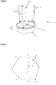
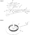
- a vertical axis wind turbine 1 comprises three turbine blades 2 which rotate around a central vertical rod 3 defining a vertical axis.
- This vertical rod is coupled to the turbine blades by pairs of arms 4 which connect to the tops and bottoms of each turbine blade 2.
- the horizontal support arms 4 are rigidly connected to the central vertical rod 3 and the central vertical rod 3 can rotate about a support 5 at its base 6.
- the central vertical rod 3, horizontal support arms 4 and blades 2 together form the rotor of the vertical axis wind turbine 1.
- Each blade has two portions (see Figure 5 ); a leading blade portion 7 and a trailing blade portion 8.
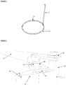
- each blade 9 is coupled to a pair of guide rails 10, 11 which are themselves supported by the base 6 of the wind turbine 1, or otherwise supported and held at the bottom of the vertical axis wind turbine.
- the first, leading blade portion 7 contains a rod 65 that projects from the top 12 and bottom 13 ends of the leading blade portion, that is coupled by a bearing arrangement 14 to the horizontal blade support arms.
- the second, trailing blade portion 8 is arranged so that it can rotate relative to the leading blade portion 7 in the direction 'A' shown in Figure 4 .
- a rod 15 passes through and is coupled to the front of the trailing blade portion 8 from top 16 to bottom 17.
- the upper end 18 of this rod 15 is pivotably coupled via a bearing 19 to the front or leading blade portion 7, and at its bottom end 20 is pivotably coupled both to the leading blade portion 7 in a manner similar to that described above for the upper end via a bearing 21, and via a follower bearing 24 to a cam follower arrangement 23 which is coupled to and follows a pitch control guide rail or cam track 10.
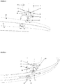
- the cam follower 23 comprises said central bearing 24 to which four rotating bearings 25 are attached.
- the four bearings are placed around the guide rail 10 which comprises a circular plate-like element. This arrangement means that the pitch or angle of the leading blade portion 7 varies with the radial distance between the ends of the horizontal support arms 4 and the respective portion of the pitch control guide rail 10.
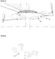
- a U-shaped arm 29 is rigidly connected to a connecting arm 28, which in turn is rigidly connected to the bottom end 20 of rod 15.
- This arm arrangement 28, 29 is used to pivotably couple the bottom end 20 of rod 15, via bearing 27, to a second cam follower 30 which engages a camber controlled guide rail or cam track 11.
- the camber cam follower is similar to the pitch cam follower in comprising said single central bearing 27 to which four bearings 26 are attached as described above for the pitch cam follower 23.
- the four bearings 26 are placed around a circular plate-like guide rail 11 which defines the camber guide rail or cam track.
- the cam follower 30 is mounted on the bottom of the arm arrangement 28, 29 by said central bearing 27.
- the arm 28, 29 is shaped such that there is room for the guide rails 10, 11 to cross over and the pitch and camber cam followers 23, 30 not to interfere with each other.
- camber guide rail 11 and its interaction with the camber follower bearing 30 results in the control of the pivoting of the trailing blade portion 8 relative to the leading blade portion 7 and thereby controllably change the camber of the blade 2.
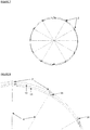
- the guide rails 10, 11 and blades 2 are arranged on a yaw mechanism 31 to rotate the mechanism as the direction of incident wind changes.
- the yaw mechanism 31 comprises a circular plate 32 rotatably coupled to the base of the turbine.
- the plate 32 has a yaw vane 33 so as to align the vane with incident wind.
- Fixings 34 are placed on the plate on which the guide rails are located as can be seen from Figure 10 .
- the guide rail fixings are located on linear actuators 35 which can controllably move the pitch and camber guide rails 10, 11.
- the linear actuators 35 can be used to controllably move the pitch and camber rails and thereby adjust the pitch and camber for different conditions.
- the linear actuators can be used to optimise the speed, as the speed of rotation increases the apparent wind and therefore pitch needs to change, and camber can be optimised for wind speed. In low wind conditions this would be to maximise speed of rotation.
- the embodiment shown in figure 13 includes a wind direction vane 60 and anemometer 61. The wind direction and speed sensed by these are used to control the linear actuators 35.
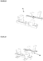
- each control comprises an offset eccentric bearing 36 and a push rod 39 connected to the pivot rod construction.
- the remainder of its construction is similar to the construction described above in connection with Figures 12 and 15 .
- the vertical axis turbine 1 comprises three turbine blades 2 which rotate around a central vertical rod 3 defining a vertical axis. This vertical rod is coupled to the turbine blades by pairs of arms 4 which connect to the tops and bottoms of each turbine blade.
- the horizontal support arms 4 are rigidly connected to the central support rod 3 and the central support rod can rotate about a support at its base.
- the central support rod, horizontal support arms and blades together form the rotor of the vertical axis wind turbine.
- leading blade portion 7 is coupled at its top and bottom ends by repetitive bearing arrangements 42 to the horizontal blade support arms 4.
- the trailing blade portion is arranged so that it can rotate relative to the leading blade portion 7.
- a rod 43 passes through the front of the trailing blade portion 8 from top to bottom.
- the upper end of this rod 43 is coupled via a bearing (not shown) to the front or leading blade portion, and at its bottom end is coupled via a bearing 44 to the front or leading blade portion 7.
- the bottom of the rod 43 is coupled via rod 46 and a bearing to a rod 39 that rigidly connects to the eccentric bearing 36 that controls the pitch of the blade.
- An L-shaped arm 47 rigidly connects to the rod 43 of the trailing blade portion horizontally in the direction of the tail of the trailing blade portion, this is coupled via a bearing to the push rod of the second eccentric bearing 37 that controls the camber of the blade.
- the eccentric bearings are arranged on a yaw mechanism 31 to rotate the mechanism as the direction of incident wind changes.
- the yaw mechanism comprises a circular plate 32 rotatably coupled to the base of the turbine.
- the plate has a yaw vane 33 so as to align the vane with incident wind.
- Fixings 34 are placed on the plate on which the eccentric bearings are located.
- the eccentric bearings are located on linear actuators 35 which can controllably move the pitch and camber eccentric bearings in one axis.
- the eccentric bearings are located on linear actuators 48 which can controllably move the pitch and camber eccentric bearings in two axes and so replace the need for a rotating yaw vane mechanism.
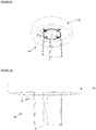
- the vertical axis turbine has been arranged with a water float 50 so as to be suitable as a floating water turbine 49.
- the connecting rod at the top of the blade has been extended so that the top horizontal support arms and control guide rails and linear actuators are not in contact with the water.
- the construction of the turbine is otherwise the same as described for the embodiments shown in figures 1 to 23 but inverted or upside down.
- Embodiments of the invention are suitable for extracting energy from any moving fluid. Suitable fluids and environments include, but are not limited to, moving air or wind, and tides.
- Suitable fluids and environments include, but are not limited to, moving air or wind, and tides.
- the embodiments of the invention described above with reference to figures 1 to 26 all have a turbine rotor axis of rotation which is substantially vertical.
- the invention is, however, equally applicable for use in situations where the rotor axis of rotation is not vertical: for example, in a cyclogiro or in a shallow water tidal current device in which the axis of rotation would be substantially horizontal.
- the skilled man would readily appreciate that the construction of such a turbine would be similar to that described above in connection with figures 1 to 26 .
Landscapes
- Engineering & Computer Science (AREA)
- Combustion & Propulsion (AREA)
- General Engineering & Computer Science (AREA)
- Mechanical Engineering (AREA)
- Chemical & Material Sciences (AREA)
- Sustainable Energy (AREA)
- Life Sciences & Earth Sciences (AREA)
- Sustainable Development (AREA)
- Wind Motors (AREA)
- Hydraulic Turbines (AREA)
- Vehicle Body Suspensions (AREA)
- Other Liquid Machine Or Engine Such As Wave Power Use (AREA)
- Engine Equipment That Uses Special Cycles (AREA)
- Superconductors And Manufacturing Methods Therefor (AREA)
Priority Applications (4)
| Application Number | Priority Date | Filing Date | Title |
|---|---|---|---|
| SI201331593T SI2923081T1 (sl) | 2012-11-26 | 2013-11-26 | Turbina z navpično osjo |
| RSP20191329 RS59427B1 (sr) | 2012-11-26 | 2013-11-26 | Turbina sa vertikalnom osom |
| PL13814443T PL2923081T3 (pl) | 2012-11-26 | 2013-11-26 | Turbina o osi pionowej |
| HRP20191870TT HRP20191870T1 (hr) | 2012-11-26 | 2019-10-15 | Turbina s vertikalnom osi |
Applications Claiming Priority (2)
| Application Number | Priority Date | Filing Date | Title |
|---|---|---|---|
| GB1221260.1A GB2510554B (en) | 2012-11-26 | 2012-11-26 | Turbine with Two Part Blade having Pitch and Camber Control |
| PCT/EP2013/074704 WO2014080030A1 (en) | 2012-11-26 | 2013-11-26 | Vertical axis turbine |
Publications (2)
| Publication Number | Publication Date |
|---|---|
| EP2923081A1 EP2923081A1 (en) | 2015-09-30 |
| EP2923081B1 true EP2923081B1 (en) | 2019-07-31 |
Family
ID=47560696
Family Applications (1)
| Application Number | Title | Priority Date | Filing Date |
|---|---|---|---|
| EP13814443.1A Active EP2923081B1 (en) | 2012-11-26 | 2013-11-26 | Vertical axis turbine |
Country Status (22)
| Country | Link |
|---|---|
| US (1) | US9644604B2 (hu) |
| EP (1) | EP2923081B1 (hu) |
| JP (1) | JP6072282B2 (hu) |
| KR (1) | KR101732604B1 (hu) |
| CN (1) | CN104884792B (hu) |
| AU (1) | AU2013349621B2 (hu) |
| BR (1) | BR112015012137B1 (hu) |
| CA (1) | CA2892210C (hu) |
| CY (1) | CY1122262T1 (hu) |
| DK (1) | DK2923081T3 (hu) |
| ES (1) | ES2751405T3 (hu) |
| GB (1) | GB2510554B (hu) |
| HR (1) | HRP20191870T1 (hu) |
| HU (1) | HUE046789T2 (hu) |
| LT (1) | LT2923081T (hu) |
| MX (1) | MX357626B (hu) |
| PL (1) | PL2923081T3 (hu) |
| PT (1) | PT2923081T (hu) |
| RS (1) | RS59427B1 (hu) |
| SI (1) | SI2923081T1 (hu) |
| TW (1) | TWI647385B (hu) |
| WO (1) | WO2014080030A1 (hu) |
Families Citing this family (22)
| Publication number | Priority date | Publication date | Assignee | Title |
|---|---|---|---|---|
| EP2957768A1 (en) * | 2014-06-16 | 2015-12-23 | Cockerill Maintenance & Ingenierie S.A. | Improved vertical axis wind turbine |
| WO2015197878A1 (es) * | 2014-06-25 | 2015-12-30 | Renewable Innovative Sustainable Power, S.L. | Aerogenerador de eje vertical |
| GB2531800A (en) * | 2014-10-31 | 2016-05-04 | Gkinetic Energy Ltd | Water turbine assembly |
| GB201421296D0 (en) * | 2014-12-01 | 2015-01-14 | Mahfoud Gaby | Floating wind powered structure |
| US20180030956A1 (en) * | 2015-02-05 | 2018-02-01 | Vijay Rao | Fluid Turbine with Control System |
| US20160230742A1 (en) * | 2015-02-05 | 2016-08-11 | Vijay Rao | Wind Turbine |
| US10495069B2 (en) * | 2016-01-22 | 2019-12-03 | Noel Richard Potter | Stabilizing a wind turbine assembly |
| US11118565B2 (en) * | 2016-03-30 | 2021-09-14 | Adv Tech | Fluidic rotor having orientable blades with improved blade control |
| EP3439953B1 (en) * | 2016-04-03 | 2020-09-02 | Optivector Ltd | Cycloidal rotor or propeller with performance and flows optimization |
| US11009005B2 (en) * | 2016-08-30 | 2021-05-18 | Guy Andrew Vaz | Turbine system |
| WO2019002923A1 (de) * | 2017-06-30 | 2019-01-03 | Agile Wind Power Ag | Vertikalwindkraftanlage mit koaxialem pitchmotor sowie bausatz für selbige und verfahren für ihren betrieb |
| ES1189058Y (es) * | 2017-07-17 | 2017-10-20 | Torrecilla Contreras Jose Antonio | Sistema de rotor, transmisión y elementos captadores que optimiza el aerogenerador de eje vertical |
| US10994840B1 (en) * | 2017-08-16 | 2021-05-04 | United States Of America As Represented By The Secretary Of The Air Force | Thrust vectoring control of a cyclorotor |
| WO2019074645A1 (en) * | 2017-10-10 | 2019-04-18 | Vijay Rao | ENHANCED FLUID TURBINE WITH CONTROL SYSTEM |
| GB201716912D0 (en) * | 2017-10-14 | 2017-11-29 | Mercer Guy Nigel | Vertical axis wind turbine |
| CN109667718A (zh) * | 2017-10-16 | 2019-04-23 | 阿润 | 一种轨道式发电机 |
| CN108252866A (zh) * | 2018-03-06 | 2018-07-06 | 大连理工大学 | 一种基于浮式风机和潮流能装置的深海能源集成系统 |
| US20200072190A1 (en) * | 2018-08-31 | 2020-03-05 | Shannon R. Buchanan | Vertical axis wind turbine |
| US10920751B2 (en) * | 2018-12-12 | 2021-02-16 | Ziaur Rahman | Orthogonal turbine having a speed adjusting member |
| WO2021127663A2 (en) * | 2019-12-19 | 2021-06-24 | Sjk Energy Solutions | Kinetic fluid energy conversion system |
| US11614754B2 (en) * | 2020-08-11 | 2023-03-28 | Pitch Aeronautics LLC | Multirotor vertical takeoff and landing aircraft with cyclorotor for lateral control |
| NO347701B1 (en) * | 2022-03-15 | 2024-02-26 | Norestraen Ind As | Vertical axis wind turbine |
Family Cites Families (23)
| Publication number | Priority date | Publication date | Assignee | Title |
|---|---|---|---|---|
| US1639545A (en) * | 1926-11-22 | 1927-08-16 | Lonnie C Weaver | Automatic control for windmills |
| FR1396515A (fr) | 1964-03-12 | 1965-04-23 | Moteur à axe vertical et à ailes orientables entraîné par un écoulement filuide | |
| US4383801A (en) * | 1981-03-02 | 1983-05-17 | Pryor Dale H | Wind turbine with adjustable air foils |
| US4619585A (en) * | 1983-07-28 | 1986-10-28 | Joe Storm | Wind turbine apparatus |
| US5324164A (en) * | 1991-06-13 | 1994-06-28 | Doering John N | Fluid active device |
| US5193978A (en) * | 1991-09-23 | 1993-03-16 | Bill Gutierrez | Articulated blade with automatic pitch and camber control |
| US5503525A (en) * | 1992-08-12 | 1996-04-02 | The University Of Melbourne | Pitch-regulated vertical access wind turbine |
| WO2004079187A1 (ja) * | 2003-03-03 | 2004-09-16 | Nikken Engineering Co., Ltd. | 発電装置及び翼装置 |
| US7365448B2 (en) * | 2006-08-17 | 2008-04-29 | X Blade Systems Lp | Wind driven power generator |
| US7911076B2 (en) * | 2006-08-17 | 2011-03-22 | Broadstar Developments, Lp | Wind driven power generator with moveable cam |
| FR2924180A1 (fr) | 2007-11-23 | 2009-05-29 | Patrick Marie Etienne | Moteur eolien a pales verticales orientables. |
| SE531944C2 (sv) | 2007-12-20 | 2009-09-15 | Liljeholm Konsult Ab | Anordning för att reglera anfallsvinkeln i vindturbiner samt metod för att kontrollera denna |
| US8193657B2 (en) | 2008-04-15 | 2012-06-05 | Michael A. Paluszek | Vertical axis wind turbine using individual blade pitch and camber control integrated with matrix converter |
| US20100054936A1 (en) | 2008-08-27 | 2010-03-04 | Sneeringer Charles P | Vertical axis wind turbine |
| KR20100070532A (ko) | 2008-12-18 | 2010-06-28 | 서울대학교산학협력단 | 풍력 발전기 |
| US8373297B2 (en) * | 2009-01-16 | 2013-02-12 | Charles Grigg | Wind turbine generator and motor |
| CN101776041B (zh) * | 2010-02-04 | 2012-05-09 | 河海大学 | 一种变桨距型垂直轴风轮 |
| DE202010002046U1 (de) | 2010-02-09 | 2011-06-09 | Matsak, Anatolij, Dipl.-Ing., 30177 | Computergesteuert Wind- Wasserturbine Matsak |
| WO2011130797A1 (en) * | 2010-04-18 | 2011-10-27 | Brian Kinloch Kirke | Improved cross flow wind or hydrokinetic turbines |
| FR2960267A1 (fr) | 2010-05-20 | 2011-11-25 | Bernard Notteghem | Turbogenerateur a rotor a pales a incidence adaptee au vent apparent |
| CN201730751U (zh) * | 2010-07-05 | 2011-02-02 | 杨寿生 | 一种可调攻角兆瓦级垂直轴风力发电机 |
| TW201224277A (en) * | 2010-12-06 | 2012-06-16 | Bai Zhen Yi | High efficiency waterwheel apparatus consisting of track-type blades and a track-type blades assembly thereof |
| TW201235558A (en) * | 2011-02-22 | 2012-09-01 | Yuh-Bin Lin | Fluid energy converter |
-
2012
- 2012-11-26 GB GB1221260.1A patent/GB2510554B/en active Active
-
2013
- 2013-11-26 CN CN201380068598.1A patent/CN104884792B/zh active Active
- 2013-11-26 AU AU2013349621A patent/AU2013349621B2/en active Active
- 2013-11-26 BR BR112015012137-3A patent/BR112015012137B1/pt active IP Right Grant
- 2013-11-26 US US14/646,897 patent/US9644604B2/en active Active
- 2013-11-26 TW TW102142964A patent/TWI647385B/zh active
- 2013-11-26 ES ES13814443T patent/ES2751405T3/es active Active
- 2013-11-26 MX MX2015006563A patent/MX357626B/es active IP Right Grant
- 2013-11-26 JP JP2015543464A patent/JP6072282B2/ja active Active
- 2013-11-26 PT PT138144431T patent/PT2923081T/pt unknown
- 2013-11-26 LT LT13814443T patent/LT2923081T/lt unknown
- 2013-11-26 KR KR1020157016770A patent/KR101732604B1/ko active IP Right Grant
- 2013-11-26 DK DK13814443T patent/DK2923081T3/da active
- 2013-11-26 WO PCT/EP2013/074704 patent/WO2014080030A1/en active Application Filing
- 2013-11-26 HU HUE13814443A patent/HUE046789T2/hu unknown
- 2013-11-26 PL PL13814443T patent/PL2923081T3/pl unknown
- 2013-11-26 CA CA2892210A patent/CA2892210C/en active Active
- 2013-11-26 EP EP13814443.1A patent/EP2923081B1/en active Active
- 2013-11-26 RS RSP20191329 patent/RS59427B1/sr unknown
- 2013-11-26 SI SI201331593T patent/SI2923081T1/sl unknown
-
2019
- 2019-10-15 HR HRP20191870TT patent/HRP20191870T1/hr unknown
- 2019-10-25 CY CY20191101118T patent/CY1122262T1/el unknown
Non-Patent Citations (1)
| Title |
|---|
| None * |
Also Published As
| Publication number | Publication date |
|---|---|
| MX2015006563A (es) | 2015-10-30 |
| ES2751405T3 (es) | 2020-03-31 |
| EP2923081A1 (en) | 2015-09-30 |
| KR101732604B1 (ko) | 2017-05-04 |
| MX357626B (es) | 2018-07-17 |
| KR20150087415A (ko) | 2015-07-29 |
| WO2014080030A1 (en) | 2014-05-30 |
| LT2923081T (lt) | 2019-10-25 |
| GB2510554B (en) | 2016-03-09 |
| CN104884792A (zh) | 2015-09-02 |
| CA2892210A1 (en) | 2014-05-30 |
| BR112015012137B1 (pt) | 2021-09-21 |
| PT2923081T (pt) | 2019-11-06 |
| DK2923081T3 (da) | 2019-11-04 |
| TWI647385B (zh) | 2019-01-11 |
| HRP20191870T1 (hr) | 2020-01-10 |
| AU2013349621A1 (en) | 2015-06-11 |
| CY1122262T1 (el) | 2020-11-25 |
| SI2923081T1 (sl) | 2019-11-29 |
| TW201437475A (zh) | 2014-10-01 |
| GB201221260D0 (en) | 2013-01-09 |
| AU2013349621B2 (en) | 2016-12-15 |
| BR112015012137A2 (pt) | 2017-07-11 |
| PL2923081T3 (pl) | 2020-03-31 |
| RS59427B1 (sr) | 2019-11-29 |
| US20150292481A1 (en) | 2015-10-15 |
| CA2892210C (en) | 2018-01-09 |
| CN104884792B (zh) | 2017-10-31 |
| JP2016502017A (ja) | 2016-01-21 |
| JP6072282B2 (ja) | 2017-02-01 |
| US9644604B2 (en) | 2017-05-09 |
| HUE046789T2 (hu) | 2020-03-30 |
| GB2510554A (en) | 2014-08-13 |
Similar Documents
| Publication | Publication Date | Title |
|---|---|---|
| EP2923081B1 (en) | Vertical axis turbine | |
| EP1888917B1 (en) | Vertical axis wind turbine having an overspeeding regulator controlling multiple aerodynamic elements | |
| US7677862B2 (en) | Vertical axis wind turbine with articulating rotor | |
| WO2009082352A1 (en) | Pitch control arrangement for wind turbine | |
| NL8102371A (nl) | Windturbine die zich op de wind stelt. | |
| KR101573758B1 (ko) | 수직축 풍력발전 장치 | |
| KR101238675B1 (ko) | 자동 피치 조절 가능한 수직축 방식 풍력발전기용 블레이드 | |
| EP2616673B1 (en) | Drive apparatus for electricity generating apparatus | |
| US20120163976A1 (en) | Vertical axis turbine blade with adjustable form | |
| US9062657B2 (en) | Horizontally oriented wind turbine | |
| WO2017021867A1 (en) | Oscillating wing power generator | |
| WO2015123738A1 (pt) | Aparelho fluidocinético | |
| JP2011085080A (ja) | 風車 | |
| KR101057125B1 (ko) | 플랩 컨트롤 장치 | |
| US20110085912A1 (en) | Propeller for a wind motor | |
| TW201534815A (zh) | 被動式週期擺動裝置 | |
| CN202811167U (zh) | 磁力可变攻角水轮机 | |
| BR102013004159B1 (pt) | Aparelho fluidocinético | |
| KR20090017341A (ko) | 윙렛형의 캠-틸팅형 블레이드를 구비하는 수직 축선 풍력터빈 |
Legal Events
| Date | Code | Title | Description |
|---|---|---|---|
| PUAI | Public reference made under article 153(3) epc to a published international application that has entered the european phase |
Free format text: ORIGINAL CODE: 0009012 |
|
| 17P | Request for examination filed |
Effective date: 20150625 |
|
| AK | Designated contracting states |
Kind code of ref document: A1 Designated state(s): AL AT BE BG CH CY CZ DE DK EE ES FI FR GB GR HR HU IE IS IT LI LT LU LV MC MK MT NL NO PL PT RO RS SE SI SK SM TR |
|
| AX | Request for extension of the european patent |
Extension state: BA ME |
|
| DAX | Request for extension of the european patent (deleted) | ||
| GRAP | Despatch of communication of intention to grant a patent |
Free format text: ORIGINAL CODE: EPIDOSNIGR1 |
|
| INTG | Intention to grant announced |
Effective date: 20190226 |
|
| GRAS | Grant fee paid |
Free format text: ORIGINAL CODE: EPIDOSNIGR3 |
|
| GRAA | (expected) grant |
Free format text: ORIGINAL CODE: 0009210 |
|
| AK | Designated contracting states |
Kind code of ref document: B1 Designated state(s): AL AT BE BG CH CY CZ DE DK EE ES FI FR GB GR HR HU IE IS IT LI LT LU LV MC MK MT NL NO PL PT RO RS SE SI SK SM TR |
|
| REG | Reference to a national code |
Ref country code: CH Ref legal event code: EP Ref country code: GB Ref legal event code: FG4D |
|
| REG | Reference to a national code |
Ref country code: AT Ref legal event code: REF Ref document number: 1161176 Country of ref document: AT Kind code of ref document: T Effective date: 20190815 |
|
| REG | Reference to a national code |
Ref country code: IE Ref legal event code: FG4D |
|
| REG | Reference to a national code |
Ref country code: DE Ref legal event code: R096 Ref document number: 602013058569 Country of ref document: DE |
|
| REG | Reference to a national code |
Ref country code: CH Ref legal event code: NV Representative=s name: TR-IP CONSULTING LLC, CH |
|
| REG | Reference to a national code |
Ref country code: RO Ref legal event code: EPE |
|
| REG | Reference to a national code |
Ref country code: DK Ref legal event code: T3 Effective date: 20191029 |
|
| REG | Reference to a national code |
Ref country code: PT Ref legal event code: SC4A Ref document number: 2923081 Country of ref document: PT Date of ref document: 20191106 Kind code of ref document: T Free format text: AVAILABILITY OF NATIONAL TRANSLATION Effective date: 20191029 |
|
| REG | Reference to a national code |
Ref country code: SE Ref legal event code: TRGR |
|
| REG | Reference to a national code |
Ref country code: NL Ref legal event code: FP |
|
| REG | Reference to a national code |
Ref country code: EE Ref legal event code: FG4A Ref document number: E018318 Country of ref document: EE Effective date: 20191021 |
|
| REG | Reference to a national code |
Ref country code: NO Ref legal event code: T2 Effective date: 20190731 |
|
| REG | Reference to a national code |
Ref country code: HR Ref legal event code: ODRP Ref document number: P20191870 Country of ref document: HR Payment date: 20191107 Year of fee payment: 7 |
|
| REG | Reference to a national code |
Ref country code: SK Ref legal event code: T3 Ref document number: E 32573 Country of ref document: SK |
|
| REG | Reference to a national code |
Ref country code: HR Ref legal event code: T1PR Ref document number: P20191870 Country of ref document: HR |
|
| REG | Reference to a national code |
Ref country code: CH Ref legal event code: PCAR Free format text: NEW ADDRESS: ROUTE DU COUTSET 18, 1485 NUVILLY (CH) |
|
| REG | Reference to a national code |
Ref country code: GR Ref legal event code: EP Ref document number: 20190403153 Country of ref document: GR Effective date: 20200213 |
|
| REG | Reference to a national code |
Ref country code: HU Ref legal event code: AG4A Ref document number: E046789 Country of ref document: HU |
|
| REG | Reference to a national code |
Ref country code: ES Ref legal event code: FG2A Ref document number: 2751405 Country of ref document: ES Kind code of ref document: T3 Effective date: 20200331 |
|
| PGFP | Annual fee paid to national office [announced via postgrant information from national office to epo] |
Ref country code: GB Payment date: 20191015 Year of fee payment: 7 |
|
| REG | Reference to a national code |
Ref country code: DE Ref legal event code: R097 Ref document number: 602013058569 Country of ref document: DE |
|
| PLBE | No opposition filed within time limit |
Free format text: ORIGINAL CODE: 0009261 |
|
| STAA | Information on the status of an ep patent application or granted ep patent |
Free format text: STATUS: NO OPPOSITION FILED WITHIN TIME LIMIT |
|
| 26N | No opposition filed |
Effective date: 20200603 |
|
| REG | Reference to a national code |
Ref country code: HR Ref legal event code: ODRP Ref document number: P20191870 Country of ref document: HR Payment date: 20201119 Year of fee payment: 8 |
|
| REG | Reference to a national code |
Ref country code: AT Ref legal event code: UEP Ref document number: 1161176 Country of ref document: AT Kind code of ref document: T Effective date: 20190731 |
|
| GBPC | Gb: european patent ceased through non-payment of renewal fee |
Effective date: 20201126 |
|
| PG25 | Lapsed in a contracting state [announced via postgrant information from national office to epo] |
Ref country code: GB Free format text: LAPSE BECAUSE OF NON-PAYMENT OF DUE FEES Effective date: 20201126 |
|
| REG | Reference to a national code |
Ref country code: HR Ref legal event code: ODRP Ref document number: P20191870 Country of ref document: HR Payment date: 20211115 Year of fee payment: 9 |
|
| REG | Reference to a national code |
Ref country code: HR Ref legal event code: ODRP Ref document number: P20191870 Country of ref document: HR Payment date: 20221123 Year of fee payment: 10 |
|
| PGFP | Annual fee paid to national office [announced via postgrant information from national office to epo] |
Ref country code: AL Payment date: 20221123 Year of fee payment: 10 |
|
| REG | Reference to a national code |
Ref country code: HR Ref legal event code: ODRP Ref document number: P20191870 Country of ref document: HR Payment date: 20231116 Year of fee payment: 11 |
|
| PGFP | Annual fee paid to national office [announced via postgrant information from national office to epo] |
Ref country code: NL Payment date: 20231116 Year of fee payment: 11 Ref country code: LU Payment date: 20231120 Year of fee payment: 11 |
|
| PGFP | Annual fee paid to national office [announced via postgrant information from national office to epo] |
Ref country code: SK Payment date: 20231116 Year of fee payment: 11 |
|
| PGFP | Annual fee paid to national office [announced via postgrant information from national office to epo] |
Ref country code: GR Payment date: 20231116 Year of fee payment: 11 |
|
| PGFP | Annual fee paid to national office [announced via postgrant information from national office to epo] |
Ref country code: MC Payment date: 20231124 Year of fee payment: 11 |
|
| PGFP | Annual fee paid to national office [announced via postgrant information from national office to epo] |
Ref country code: ES Payment date: 20231204 Year of fee payment: 11 |
|
| PGFP | Annual fee paid to national office [announced via postgrant information from national office to epo] |
Ref country code: IS Payment date: 20231116 Year of fee payment: 11 |
|
| PGFP | Annual fee paid to national office [announced via postgrant information from national office to epo] |
Ref country code: TR Payment date: 20231116 Year of fee payment: 11 Ref country code: SM Payment date: 20231123 Year of fee payment: 11 Ref country code: SI Payment date: 20231116 Year of fee payment: 11 Ref country code: SE Payment date: 20231114 Year of fee payment: 11 Ref country code: RS Payment date: 20231116 Year of fee payment: 11 Ref country code: RO Payment date: 20231121 Year of fee payment: 11 Ref country code: PT Payment date: 20231115 Year of fee payment: 11 Ref country code: NO Payment date: 20231121 Year of fee payment: 11 Ref country code: MT Payment date: 20231116 Year of fee payment: 11 Ref country code: LV Payment date: 20231116 Year of fee payment: 11 Ref country code: LT Payment date: 20231116 Year of fee payment: 11 Ref country code: IT Payment date: 20231117 Year of fee payment: 11 Ref country code: IE Payment date: 20231114 Year of fee payment: 11 Ref country code: HU Payment date: 20231119 Year of fee payment: 11 Ref country code: HR Payment date: 20231116 Year of fee payment: 11 Ref country code: FR Payment date: 20231114 Year of fee payment: 11 Ref country code: FI Payment date: 20231123 Year of fee payment: 11 Ref country code: EE Payment date: 20231116 Year of fee payment: 11 Ref country code: DK Payment date: 20231117 Year of fee payment: 11 Ref country code: DE Payment date: 20231117 Year of fee payment: 11 Ref country code: CZ Payment date: 20231116 Year of fee payment: 11 Ref country code: CY Payment date: 20231116 Year of fee payment: 11 Ref country code: CH Payment date: 20231201 Year of fee payment: 11 Ref country code: BG Payment date: 20231116 Year of fee payment: 11 Ref country code: AT Payment date: 20231116 Year of fee payment: 11 |
|
| PGFP | Annual fee paid to national office [announced via postgrant information from national office to epo] |
Ref country code: PL Payment date: 20231116 Year of fee payment: 11 Ref country code: BE Payment date: 20231117 Year of fee payment: 11 |
|
| PGFP | Annual fee paid to national office [announced via postgrant information from national office to epo] |
Ref country code: MK Payment date: 20231127 Year of fee payment: 11 |