EP2922483B1 - Trokarvorrichtung und deren verwendung - Google Patents
Trokarvorrichtung und deren verwendung Download PDFInfo
- Publication number
- EP2922483B1 EP2922483B1 EP13811133.1A EP13811133A EP2922483B1 EP 2922483 B1 EP2922483 B1 EP 2922483B1 EP 13811133 A EP13811133 A EP 13811133A EP 2922483 B1 EP2922483 B1 EP 2922483B1
- Authority
- EP
- European Patent Office
- Prior art keywords
- trocar
- sleeve
- trocar sleeve
- shaft
- regions
- Prior art date
- Legal status (The legal status is an assumption and is not a legal conclusion. Google has not performed a legal analysis and makes no representation as to the accuracy of the status listed.)
- Active
Links
- 238000000034 method Methods 0.000 claims description 18
- 239000012781 shape memory material Substances 0.000 claims description 10
- 241001465754 Metazoa Species 0.000 claims description 5
- 239000007789 gas Substances 0.000 claims description 4
- 239000007788 liquid Substances 0.000 claims description 2
- 230000007246 mechanism Effects 0.000 claims description 2
- 210000003815 abdominal wall Anatomy 0.000 description 9
- 210000000683 abdominal cavity Anatomy 0.000 description 7
- 230000006378 damage Effects 0.000 description 6
- 235000001674 Agaricus brunnescens Nutrition 0.000 description 5
- 208000027418 Wounds and injury Diseases 0.000 description 5
- 238000002674 endoscopic surgery Methods 0.000 description 5
- 238000004519 manufacturing process Methods 0.000 description 5
- 238000001356 surgical procedure Methods 0.000 description 5
- 210000001015 abdomen Anatomy 0.000 description 4
- 208000014674 injury Diseases 0.000 description 4
- 238000005452 bending Methods 0.000 description 3
- 210000001519 tissue Anatomy 0.000 description 3
- 230000008901 benefit Effects 0.000 description 2
- 238000013461 design Methods 0.000 description 2
- 230000006870 function Effects 0.000 description 2
- 238000002357 laparoscopic surgery Methods 0.000 description 2
- 239000000463 material Substances 0.000 description 2
- 238000002324 minimally invasive surgery Methods 0.000 description 2
- 210000004197 pelvis Anatomy 0.000 description 2
- 230000000149 penetrating effect Effects 0.000 description 2
- 210000004303 peritoneum Anatomy 0.000 description 2
- 238000012958 reprocessing Methods 0.000 description 2
- 206010020400 Hostility Diseases 0.000 description 1
- 206010052428 Wound Diseases 0.000 description 1
- 229910045601 alloy Inorganic materials 0.000 description 1
- 239000000956 alloy Substances 0.000 description 1
- 230000008859 change Effects 0.000 description 1
- 230000015271 coagulation Effects 0.000 description 1
- 238000005345 coagulation Methods 0.000 description 1
- 230000000052 comparative effect Effects 0.000 description 1
- 230000001419 dependent effect Effects 0.000 description 1
- 238000011161 development Methods 0.000 description 1
- 230000018109 developmental process Effects 0.000 description 1
- 238000003745 diagnosis Methods 0.000 description 1
- 230000000694 effects Effects 0.000 description 1
- 238000002474 experimental method Methods 0.000 description 1
- 230000002349 favourable effect Effects 0.000 description 1
- 238000001746 injection moulding Methods 0.000 description 1
- 238000003780 insertion Methods 0.000 description 1
- 230000037431 insertion Effects 0.000 description 1
- 230000003446 memory effect Effects 0.000 description 1
- 239000002184 metal Substances 0.000 description 1
- 210000000056 organ Anatomy 0.000 description 1
- 238000007789 sealing Methods 0.000 description 1
- 229910001285 shape-memory alloy Inorganic materials 0.000 description 1
- 229920000431 shape-memory polymer Polymers 0.000 description 1
- 239000000779 smoke Substances 0.000 description 1
- 230000006641 stabilisation Effects 0.000 description 1
- 238000011105 stabilization Methods 0.000 description 1
- 230000001954 sterilising effect Effects 0.000 description 1
- 238000004659 sterilization and disinfection Methods 0.000 description 1
- 238000011477 surgical intervention Methods 0.000 description 1
- 229910000811 surgical stainless steel Inorganic materials 0.000 description 1
- 210000001835 viscera Anatomy 0.000 description 1
Images


Classifications
-
- A—HUMAN NECESSITIES
- A61—MEDICAL OR VETERINARY SCIENCE; HYGIENE
- A61B—DIAGNOSIS; SURGERY; IDENTIFICATION
- A61B17/00—Surgical instruments, devices or methods, e.g. tourniquets
- A61B17/34—Trocars; Puncturing needles
- A61B17/3494—Trocars; Puncturing needles with safety means for protection against accidental cutting or pricking, e.g. limiting insertion depth, pressure sensors
- A61B17/3496—Protecting sleeves or inner probes; Retractable tips
-
- A—HUMAN NECESSITIES
- A61—MEDICAL OR VETERINARY SCIENCE; HYGIENE
- A61B—DIAGNOSIS; SURGERY; IDENTIFICATION
- A61B17/00—Surgical instruments, devices or methods, e.g. tourniquets
- A61B17/34—Trocars; Puncturing needles
-
- A—HUMAN NECESSITIES
- A61—MEDICAL OR VETERINARY SCIENCE; HYGIENE
- A61B—DIAGNOSIS; SURGERY; IDENTIFICATION
- A61B17/00—Surgical instruments, devices or methods, e.g. tourniquets
- A61B17/34—Trocars; Puncturing needles
- A61B17/3417—Details of tips or shafts, e.g. grooves, expandable, bendable; Multiple coaxial sliding cannulas, e.g. for dilating
- A61B17/3421—Cannulas
-
- A—HUMAN NECESSITIES
- A61—MEDICAL OR VETERINARY SCIENCE; HYGIENE
- A61B—DIAGNOSIS; SURGERY; IDENTIFICATION
- A61B17/00—Surgical instruments, devices or methods, e.g. tourniquets
- A61B17/34—Trocars; Puncturing needles
- A61B17/3478—Endoscopic needles, e.g. for infusion
-
- A—HUMAN NECESSITIES
- A61—MEDICAL OR VETERINARY SCIENCE; HYGIENE
- A61B—DIAGNOSIS; SURGERY; IDENTIFICATION
- A61B17/00—Surgical instruments, devices or methods, e.g. tourniquets
- A61B17/34—Trocars; Puncturing needles
- A61B17/3498—Valves therefor, e.g. flapper valves, slide valves
-
- A—HUMAN NECESSITIES
- A61—MEDICAL OR VETERINARY SCIENCE; HYGIENE
- A61B—DIAGNOSIS; SURGERY; IDENTIFICATION
- A61B17/00—Surgical instruments, devices or methods, e.g. tourniquets
- A61B17/34—Trocars; Puncturing needles
- A61B17/3417—Details of tips or shafts, e.g. grooves, expandable, bendable; Multiple coaxial sliding cannulas, e.g. for dilating
-
- A—HUMAN NECESSITIES
- A61—MEDICAL OR VETERINARY SCIENCE; HYGIENE
- A61B—DIAGNOSIS; SURGERY; IDENTIFICATION
- A61B17/00—Surgical instruments, devices or methods, e.g. tourniquets
- A61B2017/00831—Material properties
- A61B2017/00867—Material properties shape memory effect
-
- A—HUMAN NECESSITIES
- A61—MEDICAL OR VETERINARY SCIENCE; HYGIENE
- A61B—DIAGNOSIS; SURGERY; IDENTIFICATION
- A61B17/00—Surgical instruments, devices or methods, e.g. tourniquets
- A61B2017/00982—General structural features
- A61B2017/00986—Malecots, e.g. slotted tubes, of which the distal end is pulled to deflect side struts
-
- A—HUMAN NECESSITIES
- A61—MEDICAL OR VETERINARY SCIENCE; HYGIENE
- A61B—DIAGNOSIS; SURGERY; IDENTIFICATION
- A61B17/00—Surgical instruments, devices or methods, e.g. tourniquets
- A61B17/34—Trocars; Puncturing needles
- A61B17/3417—Details of tips or shafts, e.g. grooves, expandable, bendable; Multiple coaxial sliding cannulas, e.g. for dilating
- A61B2017/3454—Details of tips
- A61B2017/346—Details of tips with wings
-
- A—HUMAN NECESSITIES
- A61—MEDICAL OR VETERINARY SCIENCE; HYGIENE
- A61B—DIAGNOSIS; SURGERY; IDENTIFICATION
- A61B17/00—Surgical instruments, devices or methods, e.g. tourniquets
- A61B17/34—Trocars; Puncturing needles
- A61B2017/347—Locking means, e.g. for locking instrument in cannula
-
- A—HUMAN NECESSITIES
- A61—MEDICAL OR VETERINARY SCIENCE; HYGIENE
- A61B—DIAGNOSIS; SURGERY; IDENTIFICATION
- A61B17/00—Surgical instruments, devices or methods, e.g. tourniquets
- A61B17/34—Trocars; Puncturing needles
- A61B2017/348—Means for supporting the trocar against the body or retaining the trocar inside the body
- A61B2017/3482—Means for supporting the trocar against the body or retaining the trocar inside the body inside
- A61B2017/3484—Anchoring means, e.g. spreading-out umbrella-like structure
- A61B2017/3488—Fixation to inner organ or inner body tissue
Definitions
- the invention relates to a trocar sleeve or trocar and a trocar mandrel for minimally invasive / endoscopic surgical interventions on humans and animals.
- the trocar is an instrument used in surgery to create an opening to access a body cavity, either sharply or bluntly after prior skin incision.
- the abdominal cavity is usually inflated with preheated CO 2 in order to create better visibility.
- a trocar sleeve keeps it open. It is usually a trocar mandrel or pin, which is in the trocar sleeve with a Inside diameter of 3.0 - 12 mm, for example, sits and the tip closes the opening of the trocar sleeve.
- the trocar is inserted into the abdomen, for example through the abdominal wall or the umbilical groove.
- the surgeon can then look into the abdominal cavity through an optic (endoscope) through the trocar sleeve or operate with minimally invasive surgery using gripping, cutting and other instruments within the abdominal cavity.
- optic endoscope
- the diameter of the instruments are standardized so that trocars and instruments from different manufacturers fit together).
- This can be done by a trocar head connected to the trocar sleeve, which has a gas-tight port for the aforementioned instruments.
- Modern trocar systems are either made of surgical steel or medical plastic. They are offered both as reusable or disposable instruments.
- trocar sleeves are rigid and resistant to bending in order to maintain the guiding properties for instruments during the manipulations with the instruments necessary during the operation.
- Trocars All minimally invasive interventions primarily in the area of The abdominal cavity and the pelvis share the use of trocars, to provide access to the body cavity and to introduce optics and instruments. Trocars and their daily use have become a matter of course in the field of gynecology, urology and surgery.
- Trokar systems are known in various designs both as reusable and as one-way systems. They usually consist of a trocar sleeve and a trocar mandrel which can move within the trocar sleeve and which is often equipped at its distal end with a sharp cutting edge for penetrating tissue.
- trocar systems such as the Kii Balloon Blunt System (Applied Medical), which has an inflatable balloon in the front area of the trocar sleeve. After the trocar is inserted, air is blown into the balloon, causing it to expand and prevent the trocar from slipping out.
- a disadvantage of the system is above all the arrangement of the balloon on the outside of the trocar, as a result of which the balloon has to be guided through the puncture channel, which has proven to be disadvantageous in practical use.
- an additional connection for the air supply is provided, which generally makes handling more difficult and increases the time for the surgeon to insert the trocar.
- there is a risk that the balloon will be damaged due to the execution during the operation which can lead to a lack of functionality of the balloon and the risk of the trocar slipping out during the operation.
- US 2011/144447 A1 discloses a method and an apparatus for providing access, wherein the disclosed trocar sleeve is formed in several pieces and has an anchor device.
- US 2011/144440 A1 also discloses a method and apparatus for providing multi-piece surgical access Trocar sleeve with an anchor device.
- the present invention has for its object to provide an improved trocar sleeve and an improved trocar mandrel for use on humans and animals.
- One aspect of the invention relates to a trocar comprising a trocar sleeve and a trocar head.
- An aspect of the invention relates to a trocar sleeve, which is formed in one piece, comprising a first and a second region, the first region being designed for positioning within a body and having a holding means for preventing the trocar sleeve according to the invention from slipping out of the body, the Holding means has web-shaped areas which are spaced apart from one another by openings in the trocar sleeve.
- the web-shaped regions have a bent initial state, so that the web-shaped regions have a mushroomed state.
- the web-shaped regions are designed in such a way that they can change from a bent initial state to a stretched state. In the stretched state, the web-shaped regions are essentially planar, and the surface of the trocar sleeve has a substantially closed surface.
- the trocar sleeve according to the invention also has a second region which is designed to receive a trocar mandrel.
- a one-piece trocar sleeve is understood to mean a trocar sleeve which is formed from a workpiece. This can be produced, for example, using an injection molding process.
- the web-shaped regions are formed from a shape memory material or, in an embodiment not according to the invention, they are manufactured in such a way that they return to their original state after stretching.
- Shape memory materials and / or manufacturing techniques are understood to mean materials and / or manufacturing techniques which have or create a shape memory effect and which can apparently "remember” their former external shape despite a strong reshaping in the meantime.
- Such shape memory materials or manufacturing techniques are, for example, shape memory alloys and shape memory polymers and / or manufacturing techniques.
- the web-shaped areas are formed by the shape memory material or the shape such that they have a curved initial state and thus bring the first area of the trocar sleeve closer to the second area of the trocar sleeve. This causes the web-shaped areas in the first area to mushroom, which prevents them from slipping out of the body.
- the web-shaped regions are formed from a shape memory material, the shape memory material being a plastic.
- the web-shaped regions are half-shell-shaped.
- the so designed half-shell-shaped areas point with the rounded side towards the inside of the trocar sleeve.
- the web-shaped areas Towards the outside, the web-shaped areas have a substantially flat surface which has a curvature due to the cylindrical configuration of the trocar sleeve.
- the web-shaped areas are aligned with the first area. Due to the half-shell design of the web-shaped areas, these are sufficiently stable to ensure repeated stretching and bending. Due to the essentially flat surface, a risk of injury in the edge area of the recess, for example by burrs, hinges or the like, is avoided.
- the half-shell-shaped inside of the web-shaped regions preferably fits into a recess formed on the trocar mandrel during the stretching, so that the web-shaped regions and the recess engage.
- the half-shell-shaped configuration of the web-shaped regions ensures in a simple manner that the surgeon can manipulate the trocar sleeve in a simple and energy-saving manner without losing the guiding properties for the instruments to be inserted and without causing injuries at the points adjacent to the tissue or peritoneum.
- the second region is designed to be rigid.
- At least the second region preferably the entire trocar sleeve, has a substantially constant cross section, which is circular, oval or round.
- At least the second region preferably the entire trocar sleeve, has a substantially constant cross section, which is circular.
- a circular cross section offers the advantage of stabilization during manipulation with instruments.
- At least the second region preferably the entire trocar sleeve, has a substantially constant cross section, which is oval.
- An oval cross-section allows more freedom of movement for the instruments without the tolerances having to be set too tight.
- the outside of the trocar sleeve has markings for reading off its inserted length.
- the inserted length of the trocar sleeve can be determined by the markings on the outside of the trocar sleeve, thereby avoiding possible tissue or organ injuries to the patient.
- the trocar sleeve has a stop device. This stop device serves to prevent the patient from automatically slipping into the abdominal cavity or body cavity as a result of manipulation with instruments.
- the trocar sleeve is designed to be resistant to bending, with the exception of the web-shaped regions.
- the trocar sleeve has an inner diameter of 3-15 mm. In Depending on the intended use, the trocar sleeve has an inner diameter of 5 - 5.5 mm or 7 - 7.5 mm or 10 - 10.5 mm or 12 -12.5 mm.
- a trocar sleeve has a wall thickness of 0.2-2 mm over an at least substantial part of the total length.
- the trocar sleeve has a wall thickness of 0.5-1.0 mm or 0.8-1.2 mm or 1.0 mm or 1.5 mm.
- the trocar sleeve has an overall length of 70-230 mm. Depending on the intended use, the trocar sleeve has a total length of 70 - 80 mm or 80 - 90 mm or 110 - 120 mm or 150 - 160 mm or 160 - 170 mm. The aforementioned dimensions are particularly suitable for use via an access through the abdominal wall into the abdominal cavity or the pelvis.
- the trocar sleeve has an end face in the first region, which is configured in a butted manner.
- the inside of the trocar sleeve has at least one means for releasably arranging the trocar mandrel.
- the trocar mandrel is inserted into the trocar sleeve and arranged by means of the at least one means for arrangement in the trocar sleeve.
- the arrangement means can be designed, for example, as a means for a positive connection.
- the positive connection can be made by means of a locking connection made of locking groove and locking lug.
- the trocar sleeve can have a locking groove or tab as a means for arrangement. It is also conceivable that several means of arrangement are used for the arrangement.
- the trocar is made in one piece, the trocar head being molded onto a trocar sleeve according to the invention.
- the trocar is made in two pieces.
- the trocar sleeve and the trocar head are connected to one another in a liquid-tight and gas-tight manner with the interposition of a seal and / or a positive connection.
- the trocar head can generally be used several times, with only the trocar sleeve having to be made of a suitable material as a disposable item.
- the trocar is designed in two pieces, the trocar sleeve and the trocar head being detachably connected to one another.
- a seal is detachably arranged within the trocar head.
- the trocar head comprises at least one gas-tight valve and / or at least one outlet for gases and / or liquids.
- the valve and / or the outlet are used for the insufflation of gas or the discharge of smoke which arises during the coagulation and obstructs the view.
- a trocar mandrel with a first and a second region, the second region being tapered with respect to the first region and the first region having an end face.
- the face can be tapered or blunt be trained.
- a trocar mandrel is used, which has a conically tapering configuration which is adapted to the second region of the trocar sleeve in such a way or in length and diameter that, in the conification, it matches the first region of the trocar sleeve for better perforation of the abdominal wall in the Essentially corresponds.
- the first area of the trocar mandrel is shaped in such a way that the surgeon is able to perform an ergonomic procedure that is as stressful and energy-saving as possible when piercing and inserting into the body cavity.
- the trocar mandrel has recesses which are designed to receive the web-shaped regions of a trocar sleeve.
- the recesses are preferably arranged radially along the trocar mandrel, the number of recesses corresponding to the number of web-shaped regions of the trocar sleeve. For example, 1 to 8, preferably 2 to 6, particularly preferably 2, 4 or 6 recesses are arranged along the trocar mandrel.
- the recesses preferably have a semicircular cross section.
- the trocar mandrel is made in one piece.
- the trocar mandrel is formed in two pieces, the first and the second region being detachably connected.
- the first area or the second area can be used again, while the respective other area is designed as a disposable product. This can avoid increased expenses due to sterilization if only certain parts of the Trocar mandrels, for example, have to be formed from a metal or alloy.
- the trocar mandrel has at least one means for releasably arranging the trocar mandrel in the trocar sleeve according to the invention.
- the trocar mandrel is inserted into the trocar sleeve and arranged by means of the at least one means for arrangement in the trocar sleeve.
- the arrangement means can be designed, for example, as a means for a positive connection.
- the positive connection can be made by means of a locking connection made of locking groove and locking lug.
- the trocar mandrel can have a locking groove or tab as a means of arrangement. It is also conceivable that several arrangement means can be used for the arrangement.
- kits comprising a trocar sleeve and at least one trocar mandrel.
- the kit advantageously includes a trocar sleeve and a trocar mandrel with a tapered conical end face and a second trocar mandrel with a blunt rounded end face.
- FIG. 1 Another aspect not according to the invention relates to a system comprising a trocar and at least one trocar mandrel.
- the system advantageously comprises a trocar sleeve and a trocar mandrel with a tapering conical end face and a second trocar mandrel with a blunt rounded end face.
- Another example which is not part of the present invention, relates to the use of a kit for endoscopic surgery and / or diagnostics.
- Another example which is not part of the present invention, relates to the use of a system for endoscopic surgery and / or diagnostics.
- the releasable arrangement is achieved by locking a locking groove and a locking lug.
- the locking groove and locking lug are locked by a rotary movement of the trocar mandrel.
- the trocar mandrel rotates, the locking lug and locking groove engage.
- the locking of the trocar mandrel can be released by rotating the trocar mandrel in the opposite direction.
- the detachable arrangement takes place by means of a positive connection.
- a positive connection This can be designed, for example, as a clamp, plug or pin connection.
- the mushrooming of the web-shaped areas in the first area of the trocar sleeve prevents the trocar sleeve from slipping out completely or partially during the operation.
- the contact surface, which is formed by the mushroomed web-shaped areas is enlarged in such a way that they securely prevent slipping out against the inner abdominal wall.
- the web-shaped areas mushroomed in the "idle state" or “delivery state” are stretched by inserting and latching or rotating the trocar mandrel and adapted to the outer diameter of the trocar sleeve.
- the dimensions are calculated so that there is no overstretching and damage to the web-shaped areas.
- the system is already delivered in the "stretched" state, the trocar mandrel being arranged in the interior of the trocar sleeve.
- the trocar sleeve is then removed from the body, the trocar mandrel being inserted and locked again in the trocar sleeve, as a result of which the web-shaped regions remain stretched and easy removal of the trocar sleeve is ensured.
- An exemplary further aspect also relates to a method for preparing a treatment, for treatment or diagnosis in endoscopic surgery on humans or animals.
- Such a method comprises the provision of a trocar sleeve or a trocar according to the invention, an obturator / trocar mandrel and, if appropriate, the corresponding operation.
- the trocar mandrel is inserted into the trocar sleeve according to the invention, as a result of which the mushroomed web-shaped regions are stretched.
- the trocar is then punctured in the surgical area.
- the trocar mandrel is then removed from the trocar sleeve, as a result of which the stretching of the web-shaped regions is eliminated and these now mushroom in the interior of the body.
- the trocar mandrel is reinserted and the web-shaped areas are inserted again. The trocar can then be completely removed without much effort.
- the present invention provides safe, sterile access to the abdomen. Furthermore, it prevents the trocar or trocar sleeve from slipping out due to insufficient independent holding function in the abdominal wall, as could be determined by comparative experiments. It turned out that the seal (s) in the trocar head, which are supposed to guarantee the desired gas tightness, oppose the inserted instruments with a frictional resistance, which ensures a so-called entrainment effect, and the trocar sleeve in whole or in part in the abdominal wall withdraws or pulls them out completely. Another advantage of the present invention is to provide a surgical instrument that allows a secure closure of the entry opening after the end of the procedure.
- the holding means which is designed, for example, as a specially shaped mushroom, either slipping back or prevents slipping out of the stitch channel or out of the stitch channel.
- the special mushroom is dimensionally stable, which means that after opening the mushroom, a dimensionally stable state is achieved. Dimensionally stable also means that the trocar sleeve essentially retains its shape and guiding properties for instruments etc. when used as intended.
- the holding means can be formed, for example, from a shape memory material.
- a trocar sleeve according to the invention.
- the trocar sleeve 1 has a first and a second region 3, 4.
- the first region 3 has an end face at its end, which is conical.
- the trocar sleeve has a holding means 5, which is designed, for example, as a web-shaped region 6.
- These web-shaped areas can be formed, for example, from a shape memory material, for example a shape memory plastic or by special manufacturing techniques, and can have, for example, a half-shell shape in the direction of the interior of the trocar sleeve 1.
- the web-shaped regions 6 are in a curved position, so that the web-shaped regions 6 are mushroomed.
- the trocar sleeve 1 also points in the Fig. 1 a trocar head 12, which comprises, for example, a gas-tight valve 13 and at least one locking lug 15.
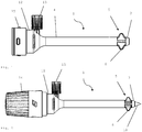
- FIG. 2 shows a trocar sleeve 1 according to the invention with an inserted trocar mandrel 2. It is recognizable that the web-shaped regions 6 are in a curved position, that is to say still in the initial state.
- a trocar mandrel 2 is arranged in the interior of the trocar sleeve 1 and likewise has a first and a second region 8, 9.
- the first region 8 has a conical taper and has a tip 10 which is designed for piercing.
- the Fig. 3 shows a schematic cross-sectional representation of the Fig. 2 ,
- the trocar mandrel 2 can clearly be seen inside the trocar sleeve 1.
- the Fig. 3 that the locking lug 15, which is arranged on the trocar head 12, is in engagement with a locking groove 16, which is arranged in the interior of the trocar handle 14.
- the locking lug 15 is snapped into the locking groove 16 by a rotary movement of the trocar mandrel handle 14, the trocar mandrel 2 being moved in the direction of the first region 3 of the trocar sleeve 1.
- the web-shaped regions 6 are stretched, as shown in FIG Fig. 4 is shown.
- the web-shaped regions 6 Due to the half-shell configuration of the web-shaped regions 6, they can be arranged in recesses 11 of the trocar mandrel 2 when stretched, so that a substantially uniform surface is formed. This is particularly important against the background of minimizing edge injuries. A constant extension of the web-shaped regions 6 is ensured by the locking of the locking lug 15 and locking groove 16. In the stretched state, the trocar is pierced in the operation area and then the locking of the locking lug 15 and locking groove 16 is released by turning in the opposite direction, so that the trocar mandrel 2 can be pulled out of the trocar sleeve 1. By releasing the latching of council nose 15 and council groove 16, the extension of the web-shaped regions 6 is canceled.
- the trocar mandrel 2 is inserted into the trocar sleeve 1, possibly with a rounded or blunt tip, and the latching nose 15 and latching groove 16 are again locked by rotating the trocar mandrel handle 14.
- the web-shaped regions 6 are stretched again, as a result of which the mushrooming is eliminated and the trocar sleeve 1 can now be removed.
- a trocar sleeve 1 with an inserted trocar mandrel 2 is shown schematically again, the web-shaped regions 6 being clearly visible in the initial state and therefore being mushroomed.
- a trocar mandrel 2 which has a first and a second region 8, 9.
- the trocar mandrel tip 10 is conically pointed to ensure easy piercing in the operating area.
- the trocar mandrel 2 has recesses 11 which are arranged along the longitudinal axis of the trocar mandrel 2. These recesses 11 are designed to receive the inside of the web-shaped regions 6, so that a substantially closed surface of the trocar sleeve 1 is formed.
- the trocar mandrel 2 is arranged in the trocar sleeve 1 by means of a clamp connection.
- the field of application of the new invention is explained using the example of an intervention.
- the intra-abdominal lumen is easily accessible via the belly button by means of a special Verresnadel and overflowing the abdomen with preheated CO2 and a special trocar, such as a camera trocar.
- the trocar sleeves or trocars according to the invention, so-called working trocars are then placed under view. Depending on the operation and execution, this can be 1-4 pieces, but usually 2 pieces.
- the actual surgical instrument (s) can be introduced via these. After completion of the intra-abdominal procedure, the instrument (s) are removed and cutaneous wound closure is carried out if necessary.
Landscapes
- Health & Medical Sciences (AREA)
- Surgery (AREA)
- Life Sciences & Earth Sciences (AREA)
- Medical Informatics (AREA)
- Nuclear Medicine, Radiotherapy & Molecular Imaging (AREA)
- Engineering & Computer Science (AREA)
- Biomedical Technology (AREA)
- Heart & Thoracic Surgery (AREA)
- Pathology (AREA)
- Molecular Biology (AREA)
- Animal Behavior & Ethology (AREA)
- General Health & Medical Sciences (AREA)
- Public Health (AREA)
- Veterinary Medicine (AREA)
- Surgical Instruments (AREA)
- Endoscopes (AREA)
Description
- Die Erfindung betrifft eine Trokarhülse bzw. Trokar sowie einen Trokardorn für minimal invasive / endoskopische chirurgische Eingriffe an Mensch und Tier.
- Die ersten Laparoskopien wurden bereits 1944 von Hans Frangenheim und Raoul Palmer publiziert. Als Pionier der laparoskopischen bzw. pelviskopischen Operationen darf jedoch Kurt Semm gelten, der mit seinen damals spektakulären Eingriffen und Erfindungen die Chirurgie revolutioniert und gegen viele Anfeindungen ab Mitte der siebziger Jahre des vorigen Jahrhunderts etabliert hat.
- In der endoskopischen und laparoskopischen Chirurgie wird mittlerweile die überwiegende Anzahl der Eingriffe minimal invasiv durchgeführt. Dies betrifft alle operativ tätigen Fachgebiete. Der Begriff minimal invasiv oder Schlüsselloch Chirurgie bezeichnet Operationstechniken über kleinste Zugänge mit speziell dafür entwickelten Instrumenten und Kameras. Trokare sind Standardinstrumente in der minimal invasiven Chirurgie, deren Anwendung spezielle Besonderheiten und Risiken beinhaltet.
- Der Trokar ist ein Instrument, mit dessen Hilfe in der Chirurgie scharf oder stumpf, nach vorheriger Hautincission, eine Öffnung als Zugang zu einer Körperhöhle geschaffen wird. Dabei wird zuvor beim Bauchraum dieser in der Regel mit vorgewärmtem CO2 aufgebläht, um bessere Sichtverhältnisse zu schaffen. Durch eine Trokarhülse wird diese offen gehalten. Es handelt sich üblicherweise um einen Trokardorn bzw. Stift, der in der Trokarhülse mit einem Innendurchmesser von z.B. 3,0 - 12 mm sitzt und dessen Spitze die Öffnung der Trokarhülse verschließt. Der Trokar wird z.B. durch die Bauchdecke oder die Nabelgrube in den Bauchraum eingeführt. Der Operateur hat dann nach dem Herausziehen des Trokardorns aus der Trokarhülse die Möglichkeit, mit einer Optik (Endoskop) durch die Trokarhülse in den Bauchraum zu schauen oder mit Greif-, Schneide- und anderen Instrumenten innerhalb des Bauchraumes minimal invasiv zu operieren. (Die Durchmesser der Instrumente sind genormt, so dass Trokare und Instrumente verschiedenster Hersteller zueinander passen). Dies kann durch einen mit der Trokarhülse verbundenen Trokarkopf geschehen, der einen gasdichten Port für die vorgenannten Instrumente aufweist. Moderne Trokar Systeme sind entweder aus chirurgischem Stahl oder medizinischem Kunststoff. Sie werden sowohl als wiederverwendbare oder Einweginstrumente angeboten. Wobei der Trend mehr und mehr zu Einweg geht, da die Aufbereitungsrichtlinien stets strenger werden und Trokare aufgrund der vorhandenen Hohlräume als sog. semikritische Instrumente für die Wiederaufbereitung eingestuft werden. Der Obturator oder Trokardorn ist an die Trokarhülse angepasst und kann sowohl eine schneidende als auch eine stumpfe Spitze aufweisen. Daneben gibt es noch sog. Sicherheitstrokare, bei denen die schneidende Spitze mit einer Klinge versehen ist, die nach dem Durchdringen der Bauchdecke zurückfährt, um eine Verletzung von inneren Organen zu vermeiden. Die Trokarhülsen können einen Ventilmechanismus oder Anschluss aufweisen, welcher zum Absaugen, Insufflieren etc. genutzt wird. Gemäß dem Stand der Technik sind Trokarhülsen starr und biegefest ausgeprägt, um die Führungseigenschaften für Instrumente bei den während der Operation nötigen Manipulationen mit den Instrumenten beizubehalten.
- Allen minimal invasiven Eingriffen vorrangig im Bereich der Bauchhöhle und der Pelvis ist die Benutzung von Trokaren, zur Schaffung des Zugangs in die Körperhöhle und zum Einbringen von Optik und Instrumenten gemein. Trokare und ihre tägliche Anwendung sind im Bereich der Gynäkologie, Urologie und Chirurgie selbstverständlich geworden.
- Trokar Systeme sind in verschiedensten Ausführungen sowohl als Mehrweg-, als auch als Einwegsysteme bekannt. Sie bestehen in der Regel aus einer Trokarhülse und einem innerhalb der Trokarhülse beweglichen Trokardorn, welcher an seinem distalen Ende oftmals mit einer scharfen Schneide zur Durchdringung von Gewebe ausgestattet ist.
- Druckschriften wie z.B.
US 2005/0251190 oderUS 2007/008827 beschreiben gasdichte Zugangswege unter Verwendung von Dichtungen und Anschluss-Systemen. Dichtungssysteme sind unter anderem auch aus denUS 4,943,280 ;US 4,655,752 ;US 4,978,341 ;EP 0 567 141 bekannt. Letztgenannte beschreibt ein Ventilsystem, das das Einführen chirurgischer Instrumente in den Körper eines Patienten insbesondere über ein Trokarsystem erlaubt. Ein gasdichter Abschluss ist für Instrumente unterschiedlicher Größe gewährleistet. - Mehr als 50% der Komplikationen erfolgen intraoperativ und somit ist schnelles Handeln des Operateurs zur Abwendung lebensbedrohlicher Situationen gefordert. Dabei kommt es gerade beim endoskopischen Operieren vor, dass in diesen außerplanmäßigen Situationen, schnell und häufig die über den Trokar eingebrachten Instrumente gewechselt werden müssen. Sehr häufig besitzen die heute im Markt befindlichen Trokare nicht die geforderte Haltefunktion z. B. in der Bauchdecke und rutschen mit dem Instrument heraus. Dadurch entstehen schnell unbeherrschbare Zustände, weil eine (zeit)aufwändige Neuplatzierung vonnöten ist. Dieser Stressfaktor für das gesamte OP Team kann zu weitergehenden Komplikationen führen. Wünschenswert wäre somit ein Trokar, der sicher in allen Situationen hält, der atraumatisch ist, der eine günstige Kosten- Nutzen- Relation aufweist und der last but not least einfach und unkompliziert "dem chirurgischen Denken" entsprechend platziert und entfernt werden kann.
- Weiterhin bekannt sind auch Trokarsysteme wie das Kii Balloon Blunt System (Applied Medical), welches einen aufblasbaren Ballon im vorderen Bereich der Trokarhülse aufweist. Nach dem Einführen des Trokars wird dabei Luft in den Ballon geblasen, wodurch dieser sich ausdehnt und ein Herausrutschen des Trokars verhindern soll. Nachteilig bei dem System ist vor allem die Anordnung des Ballons an der Außenseite des Trokars, wodurch der Ballon mit durch den Einstichkanal geführt werden muss, was sich in der praktischen Anwendung als nachteilig herausgestellt hat. Zudem ist ein zusätzlicher Anschluss für die Luftzufuhr vorgesehen, was in der Regel die Handhabung erschwert und die Zeit zur Einführung des Trokars für den Operateur verlängert. Weiterhin besteht die Gefahr, dass der Ballon aufgrund der Ausführungen unter der Operation Beschädigungen erfährt, was zu einer fehlenden Funktionalität des Ballons und der Gefahr des Herausrutschens des Trokars unter der Operation führen kann.
-
US 2011/144447 A1 offenbart ein Verfahren und eine Vorrichtung zur Schaffung eines Zugangs, wobei die offenbarte Trokarhülse mehrstückig ausgebildet ist und eine Ankervorrichtung aufweist.US 2011/144440 A1 offenbart ebenfalls ein Verfahren und eine Vorrichtung zur Schaffung eines chirurgischen Zugangs mit einer mehrstückigen Trokarhülse mit einer Ankervorrichtung. - Der vorliegenden Erfindung liegt die Aufgabe zugrunde, eine verbesserte Trokarhülse sowie einen verbesserten Trokardorn für die Anwendung an Mensch und Tier bereitzustellen.
- Diese Aufgabe wird durch einen Trokar nach Anspruch 1, ein System nach Anspruch 9 und ein Verfahren nach Anspruch 10 gelöst. Vorteilhafte Ausgestaltungen sind in den abhängigen Ansprüchen angegeben.
- Ein Aspekt der Erfindung betrifft einen Trokar umfassend eine Trokarhülse sowie einen Trokarkopf. Ein erfindungsgemäßer Aspekt der Erfindung betrifft eine Trokarhülse, welche einstückig ausgebildet ist, umfassend einen ersten und einen zweiten Bereich, wobei der erste Bereich zur Positionierung innerhalb eines Körpers ausgebildet ist und ein Haltemittel zur Vermeidung des Herausrutschens der erfindungsgemäßen Trokarhülse aus dem Körper aufweist, wobei das Haltemittel stegförmig ausgebildete Bereiche aufweist, welche durch Öffnungen in der Trokarhülse voneinander beabstandet sind. Die stegförmigen Bereiche weisen dabei einen gebeugten Ausgangszustand auf, sodass die stegförmigen Bereiche einen aufgepilzten Zustand aufweisen. Die stegförmigen Bereiche sind dabei derart ausgebildet, dass diese von einem gebeugten Ausgangszustand in einen getreckten Zustand übergehen können. Im gestreckten Zustand sind die stegförmigen Bereiche im Wesentlichen planar ausgebildet, und die Oberfläche der Trokarhülse weist eine im Wesentlichen geschlossene Oberfläche auf.
- Die erfindungsgemäße Trokarhülse weist zudem einen zweiten Bereich auf, welcher zur Aufnahme eines Trokardorns ausgebildet ist.
- Unter einer einstückigen Trokarhülse wird im Sinne der Erfindung eine Trokarhülse verstanden, welche aus einem Werkstück ausgebildet ist. Diese kann beispielsweise mittels Spritzgussverfahren hergestellt sein.
- In der Ausführungsform der Erfindung sind die stegförmigen Bereiche aus einem Formgedächtnismaterial ausgebildet bzw. in einer nicht erfindungsgemäßen Ausführungsform werden diese so gefertigt, dass sie nach dem Strecken wieder in ihren Ausgangszustand zurückkehren. Unter Formgedächtnismaterialien und/oder Fertigungstechniken werden Materialien und/oder Herstellungstechniken verstanden, welche einen Formgedächtniseffekt (shape-memory effect) aufweisen oder schaffen und sich an ihre frühere äußere Form trotz einer zwischenzeitlichen starken Umformung scheinbar "erinnern" können. Solche Formgedächtnismaterialien bzw. Herstellungstechniken sind beispielsweise Formgedächtnislegierungen und Formgedächtnispolymere und/oder Herstellungstechniken. Dabei sind die stegförmigen Bereiche durch das Formgedächtnismaterial oder die Form so ausgebildet, dass diese einen gekrümmten Ausgangszustand aufweisen und somit eine Annäherung des ersten Bereichs der Trokarhülse an den zweiten Bereich der Trokarhülse bewirken. Dadurch kommt es zu einer Aufpilzung der stegförmigen Bereiche im ersten Bereich, wodurch ein Herausrutschen aus dem Körper vermieden wird.
- In einer Ausführungsform der Erfindung sind die stegförmigen Bereiche aus einem Formgedächtnismaterial ausgebildet, wobei das Formgedächtnismaterial ein Kunststoff ist.
- In einer weiteren Ausführungsform der Erfindung sind die stegförmigen Bereiche halbschalenförmig ausgebildet. Die so gestalteten halbschalenförmigen Bereiche weisen mit der gerundeten Seite in Richtung Innenseite der Trokarhülse. In Richtung Außenseite weisen die stegförmigen Bereiche eine im Wesentlichen ebene Fläche auf, welche aufgrund der zylinderförmigen Ausgestaltung der Trokarhülse eine Krümmung aufweist. Im gestreckten Zustand sind die stegförmigen Bereiche mit dem ersten Bereich fluchtend ausgerichtet. Durch die halbschalenförmige Ausgestaltung der stegförmigen Bereiche sind diese hinreichend stabil, um eine wiederholte Streckung und Beugung zu gewährleisten. Aufgrund der im Wesentlichen ebenen Oberfläche wird zudem eine Verletzungsgefahr im Randbereich des Einstichs etwa durch Grate, Scharniere oder dergleichen vermieden. Vorzugsweise passt sich die halbschalenförmige Innenseite der stegförmigen Bereiche während der Streckung in eine am Trokardorn angeformte Ausnehmung ein, sodass die stegförmigen Bereiche und die Ausnehmung in Eingriff stehen. Die halbschalenförmige Ausgestaltung der stegförmigen Bereiche gewährleistet dabei in einfacher Weise dem Operateur eine einfache und kraftsparende Manipulation der Trokarhülse ohne dabei die Führungseigenschaften für die einzubringenden Instrumente zu verlieren und ohne an den dem Gewebe bzw. Peritoneum anliegenden Stellen Verletzungen hervorzurufen.
- In einer Ausführungsform der Erfindung ist der zweite Bereich biegesteif ausgebildet.
- In einer weiteren Ausführungsform der Erfindung weist zumindest der zweite Bereich, vorzugsweise die gesamte Trokarhülse, einen im Wesentlichen gleichbleibenden Querschnitt auf, welcher kreisförmig, oval oder rund ausgebildet ist.
- In einer weiteren Ausführungsform der Erfindung weist zumindest der zweite Bereich, vorzugsweise die gesamte Trokarhülse, einen im Wesentlichen gleichbleibenden Querschnitt auf, welcher kreisförmig ausgebildet ist. Ein kreisförmiger Querschnitt bietet den Vorteil der Stabilisierung während der Manipulation mit Instrumenten.
- In einer weiteren Ausführungsform der Erfindung weist zumindest der zweite Bereich, vorzugsweise die gesamte Trokarhülse, einen im Wesentlichen gleichbleibenden Querschnitt auf, welcher oval ausgebildet ist. Dabei erlaubt ein ovaler Querschnitt mehr Bewegungsspielraum für die Instrumente, ohne dass die Toleranzen zu eng gelegt werden müssen.
- In einer weiteren Ausführungsform der Erfindung weist die Trokarhülse außen Markierungen zum Ablesen ihrer eingeführten Länge auf. Durch die außen an der Trokarhülse angebrachten Markierungen kann die eingeführte Länge der Trokarhülse bestimmt werden, wodurch mögliche Gewebe- bzw. Organverletzungen beim Patienten vermieden werden.
- In einer weiteren Ausführungsform der Erfindung weist die Trokarhülse eine Stoppvorrichtung auf. Diese Stoppvorrichtung dient dabei der Verhinderung eines selbstständig infolge des durch Manipulationen mit Instrumenten verursachten Hineinrutschens in den Bauchraum bzw. die Körperhöhle.
- In einer weiteren Ausführungsform der Erfindung ist die Trokarhülse mit Ausnahme der stegförmigen Bereiche biegefest ausgebildet.
- In einer weiteren Ausführungsform der Erfindung weist die Trokarhülse einen Innendurchmesser von 3 - 15 mm auf. In Abhängigkeit des jeweiligen Verwendungszwecks weist die Trokarhülse einen Innendurchmesser von 5 - 5,5 mm oder 7 - 7,5 mm oder 10 - 10,5 mm oder 12 -12,5 mm auf.
- In einer weiteren Ausführungsform der Erfindung weist eine Trokarhülse über einen zumindest wesentlichen Teil der Gesamtlänge eine Wandstärke von 0,2 - 2 mm. In Abhängigkeit des jeweiligen Verwendungszwecks weist die Trokarhülse eine Wandstärke von 0,5 - 1,0 mm oder von 0,8 - 1,2 mm oder von 1,0 mm oder 1,5 mm auf.
- In einer weiteren Ausführungsform der Erfindung weist die Trokarhülse eine Gesamtlänge von 70 - 230 mm auf. In Abhängigkeit des jeweiligen Verwendungszwecks weist die Trokarhülse eine Gesamtlänge von 70 - 80 mm oder 80 - 90 mm oder 110 - 120 mm oder 150 - 160 mm oder 160 - 170 mm auf. Die zuvor genannten Maße sind besonders für die Verwendung über einen Zugang durch die Bauchdecke in den Bauchraum bzw. die Pelvis geeignet.
- In einer weiteren Ausführungsform der Erfindung weist die Trokarhülse im ersten Bereich eine Stirnseite auf, welche konifiziert ausgebildet ist.
- In der Ausführungsform der Erfindung weist die Trokarhülse im Inneren zumindest ein Mittel zur lösbaren Anordnung des Trokardorns auf. Dabei wird der Trokardorn in die Trokarhülse eingeführt und mittels des zumindest einen Mittels zur Anordnung in der Trokarhülse angeordnet. Das Mittel zur Anordnung kann dabei beispielsweise als Mittel zur formschlüssigen Verbindung ausgebildet sein. Beispielsweise kann die formschlüssige Verbindung mittels einer Rastverbindung aus Rastnut und Rastnase erfolgen. Dabei kann die Trokarhülse im Inneren als ein Mittel zur Anordnung eine Rastnut oder Rastnase aufweisen. Es ist auch denkbar, dass zur Anordnung mehrere Mittel zur Anordnung genutzt werden.
- In einer Ausführungsform der Erfindung ist der Trokar einstückig ausgeführt, wobei der Trokarkopf an einer erfindungsgemäßen Trokarhülse angeformt ist.
- In einer Ausführungsform der Erfindung ist der Trokar zweistückig ausgeführt. Dabei sind die Trokarhülse und der Trokarkopf flüssig- und gasdicht unter Zwischenlage einer Dichtung und/oder einer formschlüssigen Verbindung miteinander verbunden. Der Trokarkopf ist in der Regel mehrfach verwendbar, wobei nur die Trokarhülse als Wegwerfartikel aus einem geeigneten Material gefertigt werden müsste.
- In einer Ausführungsform der Erfindung ist der Trokar zweistückig ausgeführt, wobei die Trokarhülse und der Trokarkopf lösbar miteinander verbunden sind.
- In einer Ausführungsform der Erfindung ist innerhalb des Trokarkopfes eine Dichtung lösbar angeordnet.
- In einer Ausführungsform der Erfindung umfasst der Trokarkopf mindestens ein gasdichtes Ventil und/oder mindestens einen Auslass für Gase und/oder Flüssigkeiten. Das Ventil und/oder der Auslass werden dabei zur Insufflation von Gas oder dem Ablassen von bei der Koagulation entstehendem, die Sicht behinderndem Rauch verwendet.
- Ein weiterer Aspekt betrifft einen Trokardorn, mit einem ersten und einen zweiten Bereich, wobei der zweite Bereich gegenüber dem ersten Bereich verjüngt ausgebildet ist und wobei der erste Bereich eine Stirnseite aufweist. Die Stirnseite kann dabei konisch spitz zulaufen oder stumpf ausgebildet sein. Zu Beginn der Operation wird ein Trokardorn verwendet, der eine konisch spitz zulaufende Ausgestaltung aufweist, die derart bzw. in Länge und Durchmesser an den zweiten Bereich der Trokarhülse angepasst ist, dass sie in der Konifizierung dem ersten Bereich der Trokarhülse zum besseren Perforieren der Bauchwand im Wesentlichen entspricht. Der erste Bereich des Trokardorns ist so ausgeformt, dass es dem Operateur eine beim Einstechen und Einführen in die Körperhöhle möglichst belastungs- und kraftsparende ergonomische Vorgehensweise ermöglicht.
- Entsprechend einem weiteren Aspekt weist der Trokardorn Ausnehmungen auf, welche zur Aufnahme der stegförmigen Bereiche einer Trokarhülse ausgebildet sind. Vorzugsweise sind die Ausnehmungen radial entlang des Trokardorns angeordnet, wobei die Anzahl der Ausnehmungen der Anzahl der stegförmigen Bereiche der Trokarhülse entspricht. Beispielsweise sind 1 bis 8, vorzugsweise 2 bis 6, besonders bevorzugt 2, 4 oder 6 Ausnehmungen entlang des Trokardorns angeordnet. Vorzugsweise weisen die Ausnehmungen einen halbkreisförmigen Querschnitt auf.
- In einer Ausführungsform der Erfindung ist der Trokardorn einstückig ausgeführt.
- In einem weiteren Aspekt, welcher nicht Teil der vorliegenden Erfindung ist, ist der Trokardorn zweistückig ausgebildet, wobei der erste und der zweite Bereich lösbar verbunden sind. Dadurch kann der erste Bereich oder der zweite Bereich wieder verwendet werden, während der respektiv andere Bereich als Einweg-Produkt ausgestaltet ist. Dadurch lassen sich erhöhte Aufwendungen durch Sterilisation vermeiden, wenn nur bestimmte Teile des Trokardorns beispielsweise aus einem Metall oder -legierung ausgebildet werden müssen.
- In einer weiteren Ausführungsform der Erfindung weist der Trokardorn zumindest ein Mittel zur lösbaren Anordnung des Trokardorns in der erfindungsgemäßen Trokarhülse auf. Dabei wird der Trokardorn in die Trokarhülse eingeführt und mittels des zumindest einen Mittels zur Anordnung in der Trokarhülse angeordnet. Das Mittel zur Anordnung kann dabei beispielsweise als Mittel zur formschlüssigen Verbindung ausgebildet sein. Beispielsweise kann die formschlüssige Verbindung mittels einer Rastverbindung aus Rastnut und Rastnase erfolgen. Dabei kann der Trokardorn als ein Mittel zur Anordnung eine Rastnut oder Rastnase aufweisen. Es ist auch denkbar, dass zur Anordnung mehrere Mittel zur Anordnung genutzt werden können.
- Ein weiterer nicht erfindungsgemäßer Aspekt betrifft ein Kit umfassend eine Trokarhülse sowie zumindest einen Trokardorn. Vorteilhaft umfasst das Kit eine Trokarhülse sowie einen Trokardorn mit spitz zulaufender konischer Stirnseite sowie einen zweiten Trokardorn mit stumpfer abgerundeter Stirnseite.
- Ein weiterer nicht erfindungsgemäßer Aspekt betrifft ein System umfassend einen Trokar sowie zumindest einen Trokardorn. Vorteilhaft umfasst das System eine Trokarhülse sowie einen Trokardorn mit spitz zulaufender konischer Stirnseite sowie einen zweiten Trokardorn mit stumpfer abgerundeter Stirnseite.
- Ein weiteres Beispiel, welches nicht Teil der vorliegenden Erfindung ist, betrifft die Verwendung eines Kits zur endoskopischen Chirurgie und/oder Diagnostik.
- Ein weiteres Beispiel, welches nicht Teil der vorliegenden Erfindung ist, betrifft die Verwendung eines Systems zur endoskopischen Chirurgie und/oder Diagnostik.
- Ein weiterer Aspekt der Erfindung betrifft ein Verfahren zum Spannen stegförmiger Bereiche einer Trokarhülse des erfindungsgemäßen Trokars außerhalb des menschlichen oder tierischen Körpers umfassend die Schritte:
- Einführen eines Trokardorns in eine Trokarhülse, wobei die Stirnseite des Trokardorns im Inneren an eine Stirnseite der Trokarhülse anschlägt,
- Anordnen des Trokardorns in der Trokarhülse durch zumindest eine lösbare Anordnung, wobei ein im Inneren der Trokarhülse angeordnetes Mittel zur lösbaren Anordnung mit einem am Trokardorn angeordneten Mittel zur lösbaren Anordnung in Eingriff gelangt, sodass der Trokardorn in distaler Richtung bewegt wird, sodass die stegförmigen Bereiche durch die distale Bewegung des Trokardorns von einem gebeugten Ausgangszustand in eine gestreckte Position überführt werden, wodurch die Trokarhülse eine im Wesentlichen geschlossene Oberfläche aufweist.
- In einer Ausführungsform der Erfindung erfolgt die lösbare Anordnung durch eine Verrastung einer Rastnut und einer Rastnase.
- In einer Ausführungsform der Erfindung erfolgt Verrasten von Rastnut und Rastnase durch eine Drehbewegung des Trokardorns. Bei der Drehung des Trokardorns gelangen Rastnase und Rastnut in Eingriff. Die Verrastung des Trokardorns kann durch Drehung des Trokardorns in Gegenrichtung wieder gelöst werden.
- In einer Ausführungsform der Erfindung erfolgt die lösbare Anordnung durch eine formschlüssige Verbindung. Diese kann beispielsweise als Klemm-, Steck- oder Stiftverbindung ausgebildet sein.
- Die Aufpilzung der stegförmigen Bereiche im ersten Bereich der Trokarhülse verhindert ein komplettes oder partielles Herausrutschen der Trokarhülse unter der Operation. Infolge der Aufpilzung ist die Auflagefläche, welche durch die aufgepilzten stegförmigen Bereiche ausgebildet wird, derart vergrößert, dass diese an der Bauchinnenwand anliegend ein Herausrutschen sicher verhindern. Die im "Ruhezustand" bzw. "Auslieferungszustand" aufgepilzten stegförmigen Bereiche werden durch Einführen und Verrasten oder Drehen des Trokardorns gestreckt und auf den Außendurchmesser der Trokarhülse angepasst. Die Abmessungen sind so berechnet, dass es zu keinem Überstrecken und dadurch Beschädigen der stegförmigen Bereiche kommen kann. Es ist aber durchaus denkbar, dass das System bereits im "gestreckten" Zustand ausgeliefert wird, wobei im Inneren der Trokarhülse der Trokardorn angeordnet ist.
- Im Rahmen des beispielhaften Einsatzes in chirurgischen Anwendungen erfolgt danach das Entfernen der Trokarhülse aus dem Körper, wobei der Trokardorn erneut in die Trokarhülse eingeführt und verrastet wird, wodurch die stegförmigen Bereiche gestreckt bleiben und ein einfaches Entfernen der Trokarhülse gewährleistet wird.
- Durch die erneute Einführung und Verrasten oder Verdrehen des Trokardorns erfolgt eine Streckung der stegförmigen Bereiche im ersten Bereich der Trokarhülse, wodurch die Aufpilzung aufgehoben wird und nunmehr ein einfaches Entfernen der Trokarhülse ermöglicht wird.
- Ein beispielhafter weiterer Aspekt betrifft ebenfalls ein Verfahren zur Vorbereitung einer Behandlung, zur Behandlung bzw. Diagnostik in der endoskopischen Chirurgie an Mensch oder Tier. Ein derartiges Verfahren umfasst die Bereitstellung einer Trokarhülse bzw. eines erfindungsgemäßen Trokars, eines Obturators/Trokardorns und ggf. die entsprechende Bedienung. Dabei wird der Trokardorn in die erfindungsgemäße Trokarhülse eingeführt, wodurch die aufgepilzten stegförmigen Bereiche gestreckt werden. Danach erfolgt der Einstich des Trokars im Operationsbereich. Anschließend wird der Trokardorn aus der Trokarhülse entfernt, wodurch die Streckung der stegförmigen Bereiche aufgehoben wird und diese sich nunmehr im Inneren des Körpers aufpilzen. Nach erfolgter Operation wird der Trokardorn erneut eingeführt und die stegförmigen Bereiche wiederum gesteckt. Danach kann der Trokar vollständig ohne größeren Aufwand entfernt werden.
- Die vorliegende Erfindung ermöglicht einen sicheren, sterilen Zugang zum Bauchraum. Weiterhin verhindert sie das ungewollte Herausrutschen des Trokars bzw. der Trokarhülse aufgrund ungenügender eigenständiger Haltefunktion in der Bauchdecke, wie mittels Vergleichsversuchen festgestellt werden konnte. Dabei stellte sich heraus, dass die im Trokarkopf eingebrachte(n) Dichtung(en), welche die durchaus gewollte Gasdichtheit gewährleisten sollen, den eingebrachten Instrumenten einen Reibungswiderstand entgegensetzen, der für einen sog. Mitnahmeeffekt sorgt, und die Trokarhülse ganz oder teilweise in die Bauchdecke zurückzieht bzw. diese ganz herauszieht. Ein weiterer Vorteil der vorliegenden Erfindung ist es, ein chirurgisches Instrument anzugeben, das nach Beendigung des Eingriffes einen sicheren Verschluss der Eintrittsöffnung erlaubt.
- Der Einstich erfolgt vorzugsweise durch die Bauchwand bis das distale Ende des Trokars bzw. die nach dem Zurückziehen des Trokardorns verbleibende Trokarhülse etwas über das Peritoneum in den Bauchraum ragt, wobei das Haltemittel, welches beispielsweise als speziell geformte Aufpilzung ausgebildet ist, zum einen ein Zurückrutschen bzw. ein Herausrutschen innerhalb des Stichkanales bzw. aus dem Stichkanal verhindert. Die spezielle Aufpilzung ist formfest, was heißt, dass nach dem Öffnen der Aufpilzung ein formfester Zustand erreicht wird. Formfest heißt zudem, dass die Trokarhülse beim bestimmungsgemäßen Gebrauch im Wesentlichen ihre Form und Führungseigenschaften für Instrumente etc. beibehält. Dazu kann das Haltemittel beispielsweise aus einem Formgedächtnismaterial ausgebildet sein.
- Bevorzugte Weiterbildungen der Erfindung ergeben sich aus den Kombinationen der Ansprüche oder einzelner Merkmale davon.
- Nachfolgend soll die Erfindung anhand einiger Ausführungsbeispiele und zugehöriger Figuren eingehender erläutert werden. Die Ausführungsbeispiele sollen dabei die Erfindung beschreiben ohne diese zu beschränken.
- Es zeigen
-
Fig. 1 eine schematische Querschnittsdarstellung einer erfindungsgemäßen Trokarhülse mit einer Aufpilzung der stegförmigen Elemente im ersten Bereich der Trokarhülse, -
Fig. 2 eine schematische Darstellung einer erfindungsgemäßen Trokarhülse mit einem eingeführten Trokardorn mit einer Aufpilzung der stegförmigen Elemente im ersten Bereich der Trokarhülse, -
Fig. 3 eine schematische Querschnittsdarstellung einer erfindungsgemäßen Trokarhülse mit einem eingeführten Trokardorn mit einer Aufpilzung der stegförmigen Elemente im ersten Bereich der Trokarhülse,Fig. 4 eine weitere schematische Darstellung einer erfindungsgemäßen Trokarhülse mit eingeführtem Trokardorn und gestreckten stegförmigen Bereichen, -
Fig. 5 eine schematische Darstellung einer erfindungsgemäßen Trokarhülse mit eingeführtem Trokardorn und -
Fig. 6 eine schematische Darstellung eines Trokardorns. - In einem ersten Ausführungsbeispiel ist in
Fig. 1 schematisch eine erfindungsgemäße Trokarhülse dargestellt. Die Trokarhülse 1 weist dabei einen ersten und einen zweiten Bereich 3,4 auf. Der erste Bereich 3 weist an seinem Ende eine Stirnseite auf, welche konisch ausgeführt ist. Im ersten Bereich 3 weist die Trokarhülse ein Haltemittel 5, welches beispielsweise als stegförmige Bereiche 6 ausgebildet ist, auf. Diese stegförmigen Bereich können dabei etwa aus einem Formgedächtnismaterial, beispielsweise einem Formgedächtniskunststoff oder durch spezielle Fertigungstechniken, ausgebildet sein und beispielsweise eine halbschalenförmige Ausgestaltung in Richtung des Inneren der Trokarhülse 1 aufweisen. Dabei sind die stegförmigen Bereiche 6 im Ausgangszustand in einer gekrümmten Position, sodass eine Aufpilzung der stegförmigen Bereiche 6 ausgebildet wird. Die Trokarhülse 1 weist zudem in derFig. 1 einen Trokarkopf 12 auf, welcher beispielsweise ein gasdichtes Ventil 13 und zumindest eine Rastnase 15 umfasst. - In der
Fig. 2 ist eine erfindungsgemäße Trokarhülse 1 mit einem eingeführten Trokardorn 2 dargestellt. Dabei ist erkennbar, dass die stegförmigen Bereiche 6 in einer gekrümmten Position, also noch im Ausgangszustand sind. - Im Inneren der Trokarhülse 1 ist ein Trokardorn 2 angeordnet, welcher ebenfalls einen ersten und einen zweiten Bereich 8,9 aufweist. Der erste Bereich 8 ist dabei konisch spitz zulaufend ausgebildet und weist eine Spitze 10 auf, welche zum Einstechen ausgebildet ist.
- Die
Fig. 3 zeigt eine schematische Querschnittsdarstellung derFig. 2 . Dabei ist deutlich der Trokardorn 2 im Inneren der Trokarhülse 1 erkennbar. Zudem zeigt dieFig. 3 , dass die Rastnase 15, welche am Trokarkopf 12 angeordnet ist, mit einer Rastnut 16, welche im Inneren des Trokardorngriffs 14 angeordnet ist, im Eingriff steht. Durch eine Drehbewegung des Trokardorngriffs 14 wird die Rastnase 15 in die Rastnut 16 eingerastet, wobei der Trokardorn 2 in Richtung erster Bereich 3 der Trokarhülse 1 bewegt wird. Im Ergebnis kommt es zu einer Streckung der stegförmigen Bereiche 6, wie dies inFig. 4 abgebildet ist. Durch die halbschalenförmige Ausgestaltung der stegförmigen Bereiche 6, können diese sich bei Streckung in Ausnehmungen 11 des Trokardorns 2 anordnen, sodass eine im Wesentlichen gleichförmige Oberfläche ausgebildet wird. Diese ist insbesondere vor dem Hintergrund der Minimierung von Randverletzungen wichtig. Durch die Verrastung von Rastnase 15 und Rastnut 16 ist eine gleichbleibende Streckung der stegförmigen Bereiche 6 gewährleistet. Im gestreckten Zustand wird der Trokar im Operationsbereich eingestochen und anschließend die Verrastung von Rastnase 15 und Rastnut 16 durch Drehen in entgegengesetzter Richtung gelöst, sodass der Trokardorn 2 aus der Trokarhülse 1 herausgezogen werden kann. Durch das Lösen der Verrastung von Ratsnase 15 und Ratsnut 16 wird die Streckung der stegförmigen Bereiche 6 aufgehoben. Aufgrund der Ausgestaltung der stegförmigen Bereiche 6 aus einem Formgedächtnismaterial nehmen diese nunmehr wieder ihren Ausgangszustand, wodurch es zu einer Aufpilzung kommt. Durch diese Aufpilzung, welche im Lumen erfolgt, wird ein Herausrutschen der Trokarhülse 1 verhindert. - Zum Entfernen der Trokarhülse nach Beendigung der Operation, wird der Trokardorn 2 ggf. mit abgerundeter oder stumpfer Spitze in die Trokarhülse 1 eingeführt und durch Drehung am Trokardorngriff 14 wiederum eine Verrastung von Rastnase 15 und Rastnut 16 bewirkt. Dadurch erfolgt erneut eine Streckung der stegförmigen Bereiche 6, wodurch die Aufpilzung aufgehoben wird und die Trokarhülse 1 nunmehr entfernt werden kann.
- In der
Fig. 5 ist noch einmal schematisch eine Trokarhülse 1 mit eingeführtem Trokardorn 2 dargestellt, wobei sich die stegförmigen Bereiche 6 deutlich sichtbar im Ausgangszustand befinden und daher aufgepilzt sind. - In der
Fig. 6 ist ein Trokardorn 2 dargestellt, welcher einen ersten und einen zweiten Bereich 8,9 aufweist. Die Trokardornspitze 10 ist konisch spitz ausgebildet, um ein einfaches Einstechen im Operationsbereich zu gewährleisten. Zudem weist der Trokardorn 2 Ausnehmungen 11 auf, welche entlang der Längsachse des Trokardorn 2 angeordnet sind. Diese Ausnehmungen 11 sind dabei so ausgestaltet, um die Innenseite der stegförmigen Bereiche 6 aufzunehmen, sodass eine im Wesentlichen geschlossene Oberfläche der Trokarhülse 1 ausgebildet wird. - In einem weiteren nicht näher dargestellten Ausführungsbeispiel erfolgt die Anordnung des Trokardorns 2 in der Trokarhülse 1 mittels einer Klemmverbindung.
- Am Beispiel einer Intervention wird das Einsatzfeld der neuen Erfindung erklärt. Das intraabdominale Lumen ist mittels einer speziellen Verresnadel und dem Überblähen des Abdomens mit vorgewärmtem CO2 sowie eines speziellen Trokars, wie etwa eines Kameratrokars, über den Bauchnabel leicht zugänglich. Danach werden unter Sicht die erfindungsgemäßen Trokarhülsen bzw. Trokare, sogenannte Arbeitstrokare, platziert. Dies können je nach Operation und Ausführung 1-4 Stück sein, in der Regel jedoch 2 Stück. Über diese kann das/die eigentliche(n) Operationsinstrument(e) eingeführt werden. Nach Beendigung der intraabdominalen Prozedur wird das/die Instrument(e) entfernt und es erfolgt ggf. der kutane Wundverschluss.
-
- 1
- Trokarhülse
- 2
- Trokardorn
- 3
- erster Bereich der Trokarhülse
- 4
- zweiter Bereich der Trokarhülse
- 5
- Haltemittel
- 6
- stegförmiger Bereich
- 7
- Stirnseite des ersten Bereichs der Trokarhülse
- 8
- konisch spitz zulaufender erster Bereich des Trokardorns
- 9
- zweiter Bereich des Trokardorns
- 10
- Spitze des Trokardorns
- 11
- Ausnehmungen
- 12
- Trokarkopf
- 13
- gasdichtes Ventil
- 14
- Trokardorngriff
- 15
- Rastnase
- 16
- Rastnut
Claims (13)
- Trokar umfassend eine Trokarhülse (1) sowie einen Trokarkopf (12), wobei die Trokarhülse (1) einen ersten und einen zweiten Bereich (3,4) umfasst, wobei- der erste Bereich (3) zur Positionierung innerhalb eines Körpers ist und ein Haltemittel (5) zur Vermeidung des Herausrutschens der Trokarhülse (1) aus dem Körper aufweist, wobei das Haltemittel (5) stegförmig ausgebildete Bereiche (6) aufweist, welche durch Öffnungen (11) in der Trokarhülse (1) voneinander beabstandet die stegförmigen Bereiche (6) aus einem Formgedächtnismaterial ausgebildet sind, wobei die stegförmigen Bereiche (6) einen gebeugten Ausgangszustand aufweisen, wodurch die stegförmigen Bereiche (6) einen aufgepilzten Zustand aufweisen, und- der zweite Bereich (4) zur Aufnahme eines Trokardorns (2) ausgebildet ist und wobei die Trokarhülse (1) im Inneren zumindest ein Mittel zur lösbaren Anordnung (15) eines Trokardorns (2) aufweist, wobei das im Inneren der Trokarhülse (1) angeordnete Mittel zur lösbaren Anordnung (15) derart ausgebildet ist, um mit einem am Trokardorn (2) angeordneten Mittel zur lösbaren Anordnung (16) in Eingriff zu gelangen, dadurch gekennzeichnet, dass die Trokarhülse (1) einstückig ausgebildet ist.
- Trokar nach Anspruch 1, wobei die stegförmigen Bereiche (6) halbschalenförmig ausgebildet sind.
- Trokar nach einem der vorhergehenden Ansprüche, wobei die Trokarhülse (1) außen Markierungen zum Ablesen seiner eingeführten Länge aufweist.
- Trokar nach einem der vorhergehenden Ansprüche, wobei die Trokarhülse (1) einen Innendurchmesser von 3 - 15 mm, über einen zumindest wesentlichen Teil der Gesamtlänge eine Wandstärke von ca. 0,2 - 2 mm und eine Gesamtlänge von 70 - 230 mm aufweist.
- Trokar nach einem der vorhergehenden Ansprüche, wobei die Trokarhülse (1) eine Rastnase (15) zur Anordnung des Trokardorns (2) aufweist.
- Trokar nach einem der vorhergehenden Ansprüche, wobei der Trokar einstückig ausgeführt ist.
- Trokar nach einem der Ansprüche 1 bis 5, wobei der Trokar zweistückig ausgeführt ist, wobei die Trokarhülse (1) und der Trokarkopf (12) lösbar miteinander verbunden sind.
- Trokar nach einem der vorhergehenden Ansprüche, wobei der Trokarkopf (12) mindestens ein gasdichtes Ventil und/oder mindestens einen Ein- oder Auslass für Gase und/oder Flüssigkeiten umfasst.
- System umfassend einen Trokar nach einem der Ansprüche 1 bis 8 sowie zumindest einen Trokardorn (2) mit einem ersten und einen zweiten Bereich (8,9), wobei der erste Bereich (8) eine Stirnseite (10) aufweist, wobei der Trokardorn (2) Ausnehmungen (11) aufweist, welche zur Aufnahme der stegförmigen Bereiche (6) einer Trokarhülse (1) ausgebildet sind, wobei der Trokardorn (2) einstückig ausgebildet ist.
- Verfahren zum Spannen stegförmiger Bereiche (6) einer Trokarhülse (1) eines Trokars nach einem der Ansprüche 1 bis 8 außerhalb des menschlichen oder tierischen Körpers umfassend die Schritte:- Einführen eines Trokardorns (2) in eine Trokarhülse (1), wobei die Stirnseite des Trokardorns (10) im Inneren an eine Stirnseite der Trokarhülse (5) anschlägt,- Anordnen des Trokardorns (2) in der Trokarhülse (1) durch zumindest eine lösbare Anordnung, wobei ein im Inneren der Trokarhülse (1) angeordnetes Mittel zur lösbaren Anordnung (15) mit einem am Trokardorn (2) angeordneten Mittel zur lösbaren Anordnung (16) in Eingriff gelangt, sodass der Trokardorn (2) in distaler Richtung bewegt wird, sodass die stegförmigen Bereiche (6) durch die distale Bewegung des Trokardorns (2) von einem gebeugten Ausgangszustand in eine gestreckte Position überführt werden, wodurch die Trokarhülse (1) eine im Wesentlichen geschlossene Oberfläche aufweist.
- Verfahren nach Anspruch 10, wobei die lösbare Anordnung durch eine formschlüssige Verbindung erfolgt.
- Verfahren nach einem der Ansprüche 10 oder 11, wobei die lösbare Anordnung durch Verrastung von Trokardorn (2) und Trokarhülse (1) durch einen Rastmechanismus erfolgt.
- Verfahren nach Anspruch 12, wobei die Verrastung von Rastnut (15) und Rastnase (16) durch Verdrehen des Trokardorns (2) in der Trokarhülse (1) erfolgt.
Applications Claiming Priority (2)
| Application Number | Priority Date | Filing Date | Title |
|---|---|---|---|
| DE102012111192 | 2012-11-20 | ||
| PCT/EP2013/074063 WO2014079807A2 (de) | 2012-11-20 | 2013-11-18 | Trokarvorrichtung und deren verwendung |
Publications (2)
| Publication Number | Publication Date |
|---|---|
| EP2922483A2 EP2922483A2 (de) | 2015-09-30 |
| EP2922483B1 true EP2922483B1 (de) | 2020-01-01 |
Family
ID=49841632
Family Applications (1)
| Application Number | Title | Priority Date | Filing Date |
|---|---|---|---|
| EP13811133.1A Active EP2922483B1 (de) | 2012-11-20 | 2013-11-18 | Trokarvorrichtung und deren verwendung |
Country Status (4)
| Country | Link |
|---|---|
| US (1) | US9795409B2 (de) |
| EP (1) | EP2922483B1 (de) |
| JP (1) | JP2015534868A (de) |
| WO (1) | WO2014079807A2 (de) |
Families Citing this family (11)
| Publication number | Priority date | Publication date | Assignee | Title |
|---|---|---|---|---|
| DE102015012964B4 (de) * | 2015-10-08 | 2018-12-27 | Karl Storz Se & Co. Kg | Zugangssystem für endoskopische Operationen |
| KR101725235B1 (ko) * | 2015-12-01 | 2017-04-11 | 충남대학교산학협력단 | 외과용 트로카 |
| CN105962999A (zh) * | 2016-04-20 | 2016-09-28 | 中国人民解放军第四军医大学 | 用于前纵隔微创手术的花瓣形阻尼穿刺器及其使用方法 |
| CN106943181B (zh) * | 2017-04-19 | 2019-06-14 | 微氪医疗器械南通有限公司 | 一种外科穿刺器保护包装装置及其包装方法 |
| CN110353784A (zh) * | 2019-08-21 | 2019-10-22 | 南方医科大学珠江医院 | 一种可调节深度并固定的腹腔镜穿刺套 |
| CN111317549B (zh) * | 2020-03-03 | 2021-02-19 | 刘卫辉 | 一种通电模式下的超声内镜穿刺针系统 |
| USD956219S1 (en) | 2020-07-10 | 2022-06-28 | Covidien Lp | Port apparatus |
| USD963851S1 (en) | 2020-07-10 | 2022-09-13 | Covidien Lp | Port apparatus |
| US11471189B2 (en) | 2020-10-29 | 2022-10-18 | Covidien Lp | Surgical access device with fixation mechanism and illumination mechanism |
| US20220160393A1 (en) * | 2020-11-23 | 2022-05-26 | Covidien Lp | Surgical access device with fixation mechanism |
| US11864761B2 (en) | 2021-09-14 | 2024-01-09 | Covidien Lp | Surgical instrument with illumination mechanism |
Citations (2)
| Publication number | Priority date | Publication date | Assignee | Title |
|---|---|---|---|---|
| US3713447A (en) * | 1971-08-16 | 1973-01-30 | E Adair | Suprapubic shunt |
| EP0537758A1 (de) * | 1991-10-18 | 1993-04-21 | Dexide, Inc. | Vorrichtung zum Festhalten von Gewebe zum Gebrauch mit Kanüle oder Trokar |
Family Cites Families (18)
| Publication number | Priority date | Publication date | Assignee | Title |
|---|---|---|---|---|
| US3490457A (en) * | 1967-02-06 | 1970-01-20 | Roy A Petersen | Catheter |
| US4655752A (en) | 1983-10-24 | 1987-04-07 | Acufex Microsurgical, Inc. | Surgical cannula |
| US4943280A (en) | 1987-12-31 | 1990-07-24 | United States Surgical Corporaiton | Self-seating flapper valve for an insufflation cannula assembly |
| DE8904025U1 (de) | 1988-04-07 | 1989-05-24 | Schneider (Europe) AG, Zürich | Einführungsschleuse in einem Schlauchverbindungsstück für eine Katheteranordnung |
| CA2022069C (en) | 1989-08-15 | 2001-01-02 | Daniel Shichman | Trocar penetration depth indicator and guide tube positioning device |
| CA2093748C (en) | 1992-04-24 | 1996-11-12 | Roy D. Gravener | Valve assembly for introducing instruments into body cavities |
| US5836913A (en) | 1997-05-02 | 1998-11-17 | Innerdyne, Inc. | Device and method for accessing a body cavity |
| US8398666B2 (en) | 2000-05-16 | 2013-03-19 | Teleflex Medical Incorporated | Penetrating tip for trocar assembly |
| JP3833484B2 (ja) * | 2001-03-09 | 2006-10-11 | 株式会社モリタ製作所 | 医療用外套管 |
| US7344519B2 (en) * | 2001-08-31 | 2008-03-18 | Conmed Corporation | Trocar system |
| CA2523483C (en) | 2003-05-08 | 2012-07-31 | Tyco Healthcare Group Lp | Balloon dissector with balloon tip cannula |
| KR100754653B1 (ko) | 2005-07-08 | 2007-09-05 | 삼성전자주식회사 | 이동 통신 단말의 알람 설정 방법 |
| US7811251B2 (en) * | 2005-10-13 | 2010-10-12 | Tyco Healthcare Group Lp | Trocar anchor |
| US20090306586A1 (en) * | 2008-02-29 | 2009-12-10 | Lynette Ross | Laterally-expandable access cannula for accessing the interior of a hip joint |
| DE102008033375A1 (de) | 2008-07-09 | 2010-01-14 | Aesculap Ag | Chirurgische Dichtelementhalterung zum Halten eines chirurgischen Dichtelements und chirurgisches Abdichtungssystem |
| DE202009004536U1 (de) * | 2009-03-25 | 2010-08-12 | Marx, Karl-Heinz | Set zur Schaffung eines künstlichen Mageneinganges |
| US8444557B2 (en) * | 2009-12-11 | 2013-05-21 | Ethicon Endo-Surgery, Inc. | Methods and devices for providing access through tissue to a surgical site |
| US8435174B2 (en) | 2009-12-11 | 2013-05-07 | Ethicon Endo-Surgery, Inc. | Methods and devices for accessing a body cavity |
-
2013
- 2013-11-18 WO PCT/EP2013/074063 patent/WO2014079807A2/de active Application Filing
- 2013-11-18 US US14/443,864 patent/US9795409B2/en active Active
- 2013-11-18 JP JP2015542283A patent/JP2015534868A/ja active Pending
- 2013-11-18 EP EP13811133.1A patent/EP2922483B1/de active Active
Patent Citations (2)
| Publication number | Priority date | Publication date | Assignee | Title |
|---|---|---|---|---|
| US3713447A (en) * | 1971-08-16 | 1973-01-30 | E Adair | Suprapubic shunt |
| EP0537758A1 (de) * | 1991-10-18 | 1993-04-21 | Dexide, Inc. | Vorrichtung zum Festhalten von Gewebe zum Gebrauch mit Kanüle oder Trokar |
Also Published As
| Publication number | Publication date |
|---|---|
| WO2014079807A2 (de) | 2014-05-30 |
| US20150297260A1 (en) | 2015-10-22 |
| WO2014079807A3 (de) | 2014-07-17 |
| US9795409B2 (en) | 2017-10-24 |
| JP2015534868A (ja) | 2015-12-07 |
| EP2922483A2 (de) | 2015-09-30 |
Similar Documents
| Publication | Publication Date | Title |
|---|---|---|
| EP2922483B1 (de) | Trokarvorrichtung und deren verwendung | |
| EP2185061B1 (de) | Trokarrohr, trokar, obturator bzw. rektoskop für die transluminale endoskopische chirurgie über natürliche körperöffnungen | |
| EP2725989B1 (de) | Trokarsystem | |
| EP2725962B1 (de) | Trokarsystem | |
| DE69629557T2 (de) | Veress-nadel und kanülenanordnung | |
| DE69327786T2 (de) | Trokarhilfsvorrichtung für die endoskopische chirurgie | |
| EP2049037B1 (de) | Vorrichtung zum einführen und positionieren von chirurgischen instrumenten | |
| EP1269925B1 (de) | Zugangskanüle für endoskopische Operationen, insbesondere für die Arthroskopie | |
| EP0895460B1 (de) | Trokardorn mit einer spitze | |
| DE102006023637A1 (de) | Tracheostoma-Platzhalter, Tracheotomieverfahren und Vorrichtung zur Einführung eines solchen Tracheostoma-Platzhalters | |
| WO2010108678A1 (de) | Set zur schaffung eines künstlichen mageneinganges | |
| DE102012203907B4 (de) | Trokarsystem | |
| DE102012203908B3 (de) | Instrumentensystem für die minimalinvasive Chirurgie in der Single-Port-Technik | |
| DE202012012578U1 (de) | Trokar | |
| DE9109909U1 (de) | Operationsinstrument | |
| DE2835812A1 (de) | Trokar | |
| EP3409221B1 (de) | Instrumentensystem für die minimalinvasive chirurgie im gewebe eines patienten | |
| DE102016110598A1 (de) | Endoskopische Trokarhülse | |
| DE102015120776B4 (de) | Arbeitshülse für Trokar | |
| EP2915492B1 (de) | Instrument zum chirurgischen nähen bei der minimal-invasiven chirurgie und nadelhalterkupplung für ein derartiges instrument | |
| DE102010032151B4 (de) | Medizinisches Handinstrument zum Einbringen einer Inzision in die Sklera des Auges und Trokarsystem | |
| DE202010010594U1 (de) | Medizinisches Handinstrument, insbesondere Trokarlanze, und Trokarsystem | |
| WO2024027864A1 (de) | Proktoskop und verfahren zum einsatz eines proktoskops | |
| EP2589349A1 (de) | Medizinische Vorrichtung zum Einführen von endoskopischen Instrumenten in eine Körperhöhle | |
| WO2008122565A1 (de) | Trokar und einführhilfe für einen trokar |
Legal Events
| Date | Code | Title | Description |
|---|---|---|---|
| PUAI | Public reference made under article 153(3) epc to a published international application that has entered the european phase |
Free format text: ORIGINAL CODE: 0009012 |
|
| 17P | Request for examination filed |
Effective date: 20150519 |
|
| AK | Designated contracting states |
Kind code of ref document: A2 Designated state(s): AL AT BE BG CH CY CZ DE DK EE ES FI FR GB GR HR HU IE IS IT LI LT LU LV MC MK MT NL NO PL PT RO RS SE SI SK SM TR |
|
| AX | Request for extension of the european patent |
Extension state: BA ME |
|
| DAX | Request for extension of the european patent (deleted) | ||
| STAA | Information on the status of an ep patent application or granted ep patent |
Free format text: STATUS: EXAMINATION IS IN PROGRESS |
|
| 17Q | First examination report despatched |
Effective date: 20171115 |
|
| GRAP | Despatch of communication of intention to grant a patent |
Free format text: ORIGINAL CODE: EPIDOSNIGR1 |
|
| STAA | Information on the status of an ep patent application or granted ep patent |
Free format text: STATUS: GRANT OF PATENT IS INTENDED |
|
| INTG | Intention to grant announced |
Effective date: 20190220 |
|
| GRAJ | Information related to disapproval of communication of intention to grant by the applicant or resumption of examination proceedings by the epo deleted |
Free format text: ORIGINAL CODE: EPIDOSDIGR1 |
|
| STAA | Information on the status of an ep patent application or granted ep patent |
Free format text: STATUS: EXAMINATION IS IN PROGRESS |
|
| INTC | Intention to grant announced (deleted) | ||
| GRAP | Despatch of communication of intention to grant a patent |
Free format text: ORIGINAL CODE: EPIDOSNIGR1 |
|
| STAA | Information on the status of an ep patent application or granted ep patent |
Free format text: STATUS: GRANT OF PATENT IS INTENDED |
|
| INTG | Intention to grant announced |
Effective date: 20190829 |
|
| RAP1 | Party data changed (applicant data changed or rights of an application transferred) |
Owner name: KREUZ, GEROLD Owner name: KOCH, HEINRICH |
|
| GRAS | Grant fee paid |
Free format text: ORIGINAL CODE: EPIDOSNIGR3 |
|
| GRAA | (expected) grant |
Free format text: ORIGINAL CODE: 0009210 |
|
| STAA | Information on the status of an ep patent application or granted ep patent |
Free format text: STATUS: THE PATENT HAS BEEN GRANTED |
|
| AK | Designated contracting states |
Kind code of ref document: B1 Designated state(s): AL AT BE BG CH CY CZ DE DK EE ES FI FR GB GR HR HU IE IS IT LI LT LU LV MC MK MT NL NO PL PT RO RS SE SI SK SM TR |
|
| REG | Reference to a national code |
Ref country code: GB Ref legal event code: FG4D Free format text: NOT ENGLISH |
|
| REG | Reference to a national code |
Ref country code: CH Ref legal event code: EP Ref country code: AT Ref legal event code: REF Ref document number: 1218804 Country of ref document: AT Kind code of ref document: T Effective date: 20200115 |
|
| REG | Reference to a national code |
Ref country code: IE Ref legal event code: FG4D Free format text: LANGUAGE OF EP DOCUMENT: GERMAN |
|
| REG | Reference to a national code |
Ref country code: DE Ref legal event code: R096 Ref document number: 502013014155 Country of ref document: DE |
|
| REG | Reference to a national code |
Ref country code: NL Ref legal event code: MP Effective date: 20200101 |
|
| REG | Reference to a national code |
Ref country code: LT Ref legal event code: MG4D |
|
| PG25 | Lapsed in a contracting state [announced via postgrant information from national office to epo] |
Ref country code: CZ Free format text: LAPSE BECAUSE OF FAILURE TO SUBMIT A TRANSLATION OF THE DESCRIPTION OR TO PAY THE FEE WITHIN THE PRESCRIBED TIME-LIMIT Effective date: 20200101 Ref country code: NO Free format text: LAPSE BECAUSE OF FAILURE TO SUBMIT A TRANSLATION OF THE DESCRIPTION OR TO PAY THE FEE WITHIN THE PRESCRIBED TIME-LIMIT Effective date: 20200401 Ref country code: RS Free format text: LAPSE BECAUSE OF FAILURE TO SUBMIT A TRANSLATION OF THE DESCRIPTION OR TO PAY THE FEE WITHIN THE PRESCRIBED TIME-LIMIT Effective date: 20200101 Ref country code: LT Free format text: LAPSE BECAUSE OF FAILURE TO SUBMIT A TRANSLATION OF THE DESCRIPTION OR TO PAY THE FEE WITHIN THE PRESCRIBED TIME-LIMIT Effective date: 20200101 Ref country code: FI Free format text: LAPSE BECAUSE OF FAILURE TO SUBMIT A TRANSLATION OF THE DESCRIPTION OR TO PAY THE FEE WITHIN THE PRESCRIBED TIME-LIMIT Effective date: 20200101 Ref country code: PT Free format text: LAPSE BECAUSE OF FAILURE TO SUBMIT A TRANSLATION OF THE DESCRIPTION OR TO PAY THE FEE WITHIN THE PRESCRIBED TIME-LIMIT Effective date: 20200527 Ref country code: NL Free format text: LAPSE BECAUSE OF FAILURE TO SUBMIT A TRANSLATION OF THE DESCRIPTION OR TO PAY THE FEE WITHIN THE PRESCRIBED TIME-LIMIT Effective date: 20200101 |
|
| PG25 | Lapsed in a contracting state [announced via postgrant information from national office to epo] |
Ref country code: LV Free format text: LAPSE BECAUSE OF FAILURE TO SUBMIT A TRANSLATION OF THE DESCRIPTION OR TO PAY THE FEE WITHIN THE PRESCRIBED TIME-LIMIT Effective date: 20200101 Ref country code: SE Free format text: LAPSE BECAUSE OF FAILURE TO SUBMIT A TRANSLATION OF THE DESCRIPTION OR TO PAY THE FEE WITHIN THE PRESCRIBED TIME-LIMIT Effective date: 20200101 Ref country code: IS Free format text: LAPSE BECAUSE OF FAILURE TO SUBMIT A TRANSLATION OF THE DESCRIPTION OR TO PAY THE FEE WITHIN THE PRESCRIBED TIME-LIMIT Effective date: 20200501 Ref country code: HR Free format text: LAPSE BECAUSE OF FAILURE TO SUBMIT A TRANSLATION OF THE DESCRIPTION OR TO PAY THE FEE WITHIN THE PRESCRIBED TIME-LIMIT Effective date: 20200101 Ref country code: GR Free format text: LAPSE BECAUSE OF FAILURE TO SUBMIT A TRANSLATION OF THE DESCRIPTION OR TO PAY THE FEE WITHIN THE PRESCRIBED TIME-LIMIT Effective date: 20200402 Ref country code: BG Free format text: LAPSE BECAUSE OF FAILURE TO SUBMIT A TRANSLATION OF THE DESCRIPTION OR TO PAY THE FEE WITHIN THE PRESCRIBED TIME-LIMIT Effective date: 20200401 |
|
| REG | Reference to a national code |
Ref country code: DE Ref legal event code: R097 Ref document number: 502013014155 Country of ref document: DE |
|
| PG25 | Lapsed in a contracting state [announced via postgrant information from national office to epo] |
Ref country code: DK Free format text: LAPSE BECAUSE OF FAILURE TO SUBMIT A TRANSLATION OF THE DESCRIPTION OR TO PAY THE FEE WITHIN THE PRESCRIBED TIME-LIMIT Effective date: 20200101 Ref country code: SM Free format text: LAPSE BECAUSE OF FAILURE TO SUBMIT A TRANSLATION OF THE DESCRIPTION OR TO PAY THE FEE WITHIN THE PRESCRIBED TIME-LIMIT Effective date: 20200101 Ref country code: EE Free format text: LAPSE BECAUSE OF FAILURE TO SUBMIT A TRANSLATION OF THE DESCRIPTION OR TO PAY THE FEE WITHIN THE PRESCRIBED TIME-LIMIT Effective date: 20200101 Ref country code: ES Free format text: LAPSE BECAUSE OF FAILURE TO SUBMIT A TRANSLATION OF THE DESCRIPTION OR TO PAY THE FEE WITHIN THE PRESCRIBED TIME-LIMIT Effective date: 20200101 Ref country code: RO Free format text: LAPSE BECAUSE OF FAILURE TO SUBMIT A TRANSLATION OF THE DESCRIPTION OR TO PAY THE FEE WITHIN THE PRESCRIBED TIME-LIMIT Effective date: 20200101 Ref country code: SK Free format text: LAPSE BECAUSE OF FAILURE TO SUBMIT A TRANSLATION OF THE DESCRIPTION OR TO PAY THE FEE WITHIN THE PRESCRIBED TIME-LIMIT Effective date: 20200101 |
|
| PLBE | No opposition filed within time limit |
Free format text: ORIGINAL CODE: 0009261 |
|
| STAA | Information on the status of an ep patent application or granted ep patent |
Free format text: STATUS: NO OPPOSITION FILED WITHIN TIME LIMIT |
|
| 26N | No opposition filed |
Effective date: 20201002 |
|
| PG25 | Lapsed in a contracting state [announced via postgrant information from national office to epo] |
Ref country code: IT Free format text: LAPSE BECAUSE OF FAILURE TO SUBMIT A TRANSLATION OF THE DESCRIPTION OR TO PAY THE FEE WITHIN THE PRESCRIBED TIME-LIMIT Effective date: 20200101 |
|
| PG25 | Lapsed in a contracting state [announced via postgrant information from national office to epo] |
Ref country code: SI Free format text: LAPSE BECAUSE OF FAILURE TO SUBMIT A TRANSLATION OF THE DESCRIPTION OR TO PAY THE FEE WITHIN THE PRESCRIBED TIME-LIMIT Effective date: 20200101 Ref country code: PL Free format text: LAPSE BECAUSE OF FAILURE TO SUBMIT A TRANSLATION OF THE DESCRIPTION OR TO PAY THE FEE WITHIN THE PRESCRIBED TIME-LIMIT Effective date: 20200101 |
|
| PG25 | Lapsed in a contracting state [announced via postgrant information from national office to epo] |
Ref country code: MC Free format text: LAPSE BECAUSE OF FAILURE TO SUBMIT A TRANSLATION OF THE DESCRIPTION OR TO PAY THE FEE WITHIN THE PRESCRIBED TIME-LIMIT Effective date: 20200101 |
|
| REG | Reference to a national code |
Ref country code: CH Ref legal event code: PL |
|
| GBPC | Gb: european patent ceased through non-payment of renewal fee |
Effective date: 20201118 |
|
| PG25 | Lapsed in a contracting state [announced via postgrant information from national office to epo] |
Ref country code: LU Free format text: LAPSE BECAUSE OF NON-PAYMENT OF DUE FEES Effective date: 20201118 |
|
| REG | Reference to a national code |
Ref country code: BE Ref legal event code: MM Effective date: 20201130 |
|
| PG25 | Lapsed in a contracting state [announced via postgrant information from national office to epo] |
Ref country code: CH Free format text: LAPSE BECAUSE OF NON-PAYMENT OF DUE FEES Effective date: 20201130 Ref country code: LI Free format text: LAPSE BECAUSE OF NON-PAYMENT OF DUE FEES Effective date: 20201130 |
|
| PG25 | Lapsed in a contracting state [announced via postgrant information from national office to epo] |
Ref country code: IE Free format text: LAPSE BECAUSE OF NON-PAYMENT OF DUE FEES Effective date: 20201118 |
|
| PG25 | Lapsed in a contracting state [announced via postgrant information from national office to epo] |
Ref country code: GB Free format text: LAPSE BECAUSE OF NON-PAYMENT OF DUE FEES Effective date: 20201118 |
|
| REG | Reference to a national code |
Ref country code: AT Ref legal event code: MM01 Ref document number: 1218804 Country of ref document: AT Kind code of ref document: T Effective date: 20201118 |
|
| PG25 | Lapsed in a contracting state [announced via postgrant information from national office to epo] |
Ref country code: AT Free format text: LAPSE BECAUSE OF NON-PAYMENT OF DUE FEES Effective date: 20201118 |
|
| PGFP | Annual fee paid to national office [announced via postgrant information from national office to epo] |
Ref country code: FR Payment date: 20211122 Year of fee payment: 9 |
|
| PG25 | Lapsed in a contracting state [announced via postgrant information from national office to epo] |
Ref country code: TR Free format text: LAPSE BECAUSE OF FAILURE TO SUBMIT A TRANSLATION OF THE DESCRIPTION OR TO PAY THE FEE WITHIN THE PRESCRIBED TIME-LIMIT Effective date: 20200101 Ref country code: MT Free format text: LAPSE BECAUSE OF FAILURE TO SUBMIT A TRANSLATION OF THE DESCRIPTION OR TO PAY THE FEE WITHIN THE PRESCRIBED TIME-LIMIT Effective date: 20200101 Ref country code: CY Free format text: LAPSE BECAUSE OF FAILURE TO SUBMIT A TRANSLATION OF THE DESCRIPTION OR TO PAY THE FEE WITHIN THE PRESCRIBED TIME-LIMIT Effective date: 20200101 |
|
| PG25 | Lapsed in a contracting state [announced via postgrant information from national office to epo] |
Ref country code: MK Free format text: LAPSE BECAUSE OF FAILURE TO SUBMIT A TRANSLATION OF THE DESCRIPTION OR TO PAY THE FEE WITHIN THE PRESCRIBED TIME-LIMIT Effective date: 20200101 Ref country code: AL Free format text: LAPSE BECAUSE OF FAILURE TO SUBMIT A TRANSLATION OF THE DESCRIPTION OR TO PAY THE FEE WITHIN THE PRESCRIBED TIME-LIMIT Effective date: 20200101 |
|
| PG25 | Lapsed in a contracting state [announced via postgrant information from national office to epo] |
Ref country code: BE Free format text: LAPSE BECAUSE OF NON-PAYMENT OF DUE FEES Effective date: 20201130 |
|
| P01 | Opt-out of the competence of the unified patent court (upc) registered |
Effective date: 20230523 |
|
| PG25 | Lapsed in a contracting state [announced via postgrant information from national office to epo] |
Ref country code: FR Free format text: LAPSE BECAUSE OF NON-PAYMENT OF DUE FEES Effective date: 20221130 |
|
| PGFP | Annual fee paid to national office [announced via postgrant information from national office to epo] |
Ref country code: DE Payment date: 20230814 Year of fee payment: 11 |