EP2921579B1 - Support textile étirable et feuille de transfert - Google Patents
Support textile étirable et feuille de transfert Download PDFInfo
- Publication number
- EP2921579B1 EP2921579B1 EP14200617.0A EP14200617A EP2921579B1 EP 2921579 B1 EP2921579 B1 EP 2921579B1 EP 14200617 A EP14200617 A EP 14200617A EP 2921579 B1 EP2921579 B1 EP 2921579B1
- Authority
- EP
- European Patent Office
- Prior art keywords
- layer
- raised
- stretchable sheet
- fabric
- yarn
- Prior art date
- Legal status (The legal status is an assumption and is not a legal conclusion. Google has not performed a legal analysis and makes no representation as to the accuracy of the status listed.)
- Active
Links
- 239000004753 textile Substances 0.000 title description 21
- 239000004744 fabric Substances 0.000 claims description 100
- 239000000835 fiber Substances 0.000 claims description 48
- XLYOFNOQVPJJNP-UHFFFAOYSA-N water Substances O XLYOFNOQVPJJNP-UHFFFAOYSA-N 0.000 claims description 44
- 239000012528 membrane Substances 0.000 claims description 39
- 239000004814 polyurethane Substances 0.000 claims description 35
- 229920002635 polyurethane Polymers 0.000 claims description 27
- 239000010432 diamond Substances 0.000 claims description 19
- 229910003460 diamond Inorganic materials 0.000 claims description 18
- 229920000642 polymer Polymers 0.000 claims description 15
- 125000006850 spacer group Chemical group 0.000 claims description 15
- 230000004888 barrier function Effects 0.000 claims description 14
- 230000002209 hydrophobic effect Effects 0.000 claims description 10
- 239000004810 polytetrafluoroethylene Substances 0.000 claims description 6
- 229920001343 polytetrafluoroethylene Polymers 0.000 claims description 6
- 230000001788 irregular Effects 0.000 claims description 2
- 239000010410 layer Substances 0.000 description 215
- 238000009940 knitting Methods 0.000 description 45
- 210000003491 skin Anatomy 0.000 description 27
- 241000264877 Hippospongia communis Species 0.000 description 21
- 238000000034 method Methods 0.000 description 21
- 238000010276 construction Methods 0.000 description 20
- 239000003292 glue Substances 0.000 description 20
- 238000000576 coating method Methods 0.000 description 17
- 239000011248 coating agent Substances 0.000 description 16
- 230000008569 process Effects 0.000 description 15
- 230000032258 transport Effects 0.000 description 15
- 239000006260 foam Substances 0.000 description 13
- 239000000203 mixture Substances 0.000 description 12
- 238000004519 manufacturing process Methods 0.000 description 11
- 230000000903 blocking effect Effects 0.000 description 10
- 238000010521 absorption reaction Methods 0.000 description 9
- 239000007789 gas Substances 0.000 description 9
- 239000000463 material Substances 0.000 description 9
- 239000007788 liquid Substances 0.000 description 8
- 229920000742 Cotton Polymers 0.000 description 7
- 229920002334 Spandex Polymers 0.000 description 7
- 230000006399 behavior Effects 0.000 description 7
- GQSGZTBDVNUIQS-DGCLKSJQSA-N ciclonicate Chemical compound C1C(C)(C)C[C@H](C)C[C@H]1OC(=O)C1=CC=CN=C1 GQSGZTBDVNUIQS-DGCLKSJQSA-N 0.000 description 7
- 239000000412 dendrimer Substances 0.000 description 7
- 229920000736 dendritic polymer Polymers 0.000 description 7
- 230000000694 effects Effects 0.000 description 7
- 239000007921 spray Substances 0.000 description 7
- 238000013022 venting Methods 0.000 description 7
- 230000006870 function Effects 0.000 description 6
- 208000004210 Pressure Ulcer Diseases 0.000 description 5
- 239000012530 fluid Substances 0.000 description 5
- 239000002344 surface layer Substances 0.000 description 5
- 206010011985 Decubitus ulcer Diseases 0.000 description 4
- 206010072170 Skin wound Diseases 0.000 description 4
- 230000003203 everyday effect Effects 0.000 description 4
- 238000005304 joining Methods 0.000 description 4
- 210000004243 sweat Anatomy 0.000 description 4
- 210000002700 urine Anatomy 0.000 description 4
- 238000009423 ventilation Methods 0.000 description 4
- 238000005406 washing Methods 0.000 description 4
- 208000017667 Chronic Disease Diseases 0.000 description 3
- 206010013786 Dry skin Diseases 0.000 description 3
- 206010021639 Incontinence Diseases 0.000 description 3
- 230000037336 dry skin Effects 0.000 description 3
- 239000002121 nanofiber Substances 0.000 description 3
- 229920005594 polymer fiber Polymers 0.000 description 3
- 229920001296 polysiloxane Polymers 0.000 description 3
- 238000005507 spraying Methods 0.000 description 3
- 230000037303 wrinkles Effects 0.000 description 3
- 229920000297 Rayon Polymers 0.000 description 2
- 206010052428 Wound Diseases 0.000 description 2
- 208000027418 Wounds and injury Diseases 0.000 description 2
- 238000004026 adhesive bonding Methods 0.000 description 2
- 230000003292 diminished effect Effects 0.000 description 2
- 238000001035 drying Methods 0.000 description 2
- 238000007730 finishing process Methods 0.000 description 2
- 230000000474 nursing effect Effects 0.000 description 2
- 230000002940 repellent Effects 0.000 description 2
- 239000005871 repellent Substances 0.000 description 2
- 230000037380 skin damage Effects 0.000 description 2
- 230000005808 skin problem Effects 0.000 description 2
- 241000351238 Alinea Species 0.000 description 1
- 229920000079 Memory foam Polymers 0.000 description 1
- XUIMIQQOPSSXEZ-UHFFFAOYSA-N Silicon Chemical compound [Si] XUIMIQQOPSSXEZ-UHFFFAOYSA-N 0.000 description 1
- 230000008901 benefit Effects 0.000 description 1
- 239000008280 blood Substances 0.000 description 1
- 210000004369 blood Anatomy 0.000 description 1
- 210000001124 body fluid Anatomy 0.000 description 1
- 239000010839 body fluid Substances 0.000 description 1
- 230000036760 body temperature Effects 0.000 description 1
- 239000011247 coating layer Substances 0.000 description 1
- 238000003851 corona treatment Methods 0.000 description 1
- 239000006185 dispersion Substances 0.000 description 1
- 238000009826 distribution Methods 0.000 description 1
- 229920001971 elastomer Polymers 0.000 description 1
- 239000000806 elastomer Substances 0.000 description 1
- 238000001523 electrospinning Methods 0.000 description 1
- 230000002708 enhancing effect Effects 0.000 description 1
- NBVXSUQYWXRMNV-UHFFFAOYSA-N fluoromethane Chemical compound FC NBVXSUQYWXRMNV-UHFFFAOYSA-N 0.000 description 1
- 239000012943 hotmelt Substances 0.000 description 1
- 238000010030 laminating Methods 0.000 description 1
- 239000000314 lubricant Substances 0.000 description 1
- 230000014759 maintenance of location Effects 0.000 description 1
- 239000008210 memory foam Substances 0.000 description 1
- 239000002086 nanomaterial Substances 0.000 description 1
- 230000007935 neutral effect Effects 0.000 description 1
- 238000009832 plasma treatment Methods 0.000 description 1
- 229920000728 polyester Polymers 0.000 description 1
- 239000005020 polyethylene terephthalate Substances 0.000 description 1
- 229920005597 polymer membrane Polymers 0.000 description 1
- 239000011527 polyurethane coating Substances 0.000 description 1
- 230000008092 positive effect Effects 0.000 description 1
- 230000002265 prevention Effects 0.000 description 1
- 239000011241 protective layer Substances 0.000 description 1
- 230000009467 reduction Effects 0.000 description 1
- 238000011946 reduction process Methods 0.000 description 1
- 230000028327 secretion Effects 0.000 description 1
- 229910052710 silicon Inorganic materials 0.000 description 1
- 239000010703 silicon Substances 0.000 description 1
- 229920005573 silicon-containing polymer Polymers 0.000 description 1
- 238000009210 therapy by ultrasound Methods 0.000 description 1
- 230000007723 transport mechanism Effects 0.000 description 1
- 239000011800 void material Substances 0.000 description 1
- 239000002759 woven fabric Substances 0.000 description 1
Images


Classifications
-
- D—TEXTILES; PAPER
- D04—BRAIDING; LACE-MAKING; KNITTING; TRIMMINGS; NON-WOVEN FABRICS
- D04B—KNITTING
- D04B1/00—Weft knitting processes for the production of fabrics or articles not dependent on the use of particular machines; Fabrics or articles defined by such processes
- D04B1/14—Other fabrics or articles characterised primarily by the use of particular thread materials
- D04B1/18—Other fabrics or articles characterised primarily by the use of particular thread materials elastic threads
-
- A—HUMAN NECESSITIES
- A61—MEDICAL OR VETERINARY SCIENCE; HYGIENE
- A61G—TRANSPORT, PERSONAL CONVEYANCES, OR ACCOMMODATION SPECIALLY ADAPTED FOR PATIENTS OR DISABLED PERSONS; OPERATING TABLES OR CHAIRS; CHAIRS FOR DENTISTRY; FUNERAL DEVICES
- A61G7/00—Beds specially adapted for nursing; Devices for lifting patients or disabled persons
- A61G7/10—Devices for lifting patients or disabled persons, e.g. special adaptations of hoists thereto
- A61G7/1025—Lateral movement of patients, e.g. horizontal transfer
- A61G7/1026—Sliding sheets or mats
-
- D—TEXTILES; PAPER
- D10—INDEXING SCHEME ASSOCIATED WITH SUBLASSES OF SECTION D, RELATING TO TEXTILES
- D10B—INDEXING SCHEME ASSOCIATED WITH SUBLASSES OF SECTION D, RELATING TO TEXTILES
- D10B2403/00—Details of fabric structure established in the fabric forming process
- D10B2403/01—Surface features
- D10B2403/011—Dissimilar front and back faces
- D10B2403/0112—One smooth surface, e.g. laminated or coated
-
- D—TEXTILES; PAPER
- D10—INDEXING SCHEME ASSOCIATED WITH SUBLASSES OF SECTION D, RELATING TO TEXTILES
- D10B—INDEXING SCHEME ASSOCIATED WITH SUBLASSES OF SECTION D, RELATING TO TEXTILES
- D10B2403/00—Details of fabric structure established in the fabric forming process
- D10B2403/01—Surface features
- D10B2403/011—Dissimilar front and back faces
- D10B2403/0114—Dissimilar front and back faces with one or more yarns appearing predominantly on one face, e.g. plated or paralleled yarns
-
- D—TEXTILES; PAPER
- D10—INDEXING SCHEME ASSOCIATED WITH SUBLASSES OF SECTION D, RELATING TO TEXTILES
- D10B—INDEXING SCHEME ASSOCIATED WITH SUBLASSES OF SECTION D, RELATING TO TEXTILES
- D10B2403/00—Details of fabric structure established in the fabric forming process
- D10B2403/02—Cross-sectional features
- D10B2403/021—Lofty fabric with equidistantly spaced front and back plies, e.g. spacer fabrics
-
- D—TEXTILES; PAPER
- D10—INDEXING SCHEME ASSOCIATED WITH SUBLASSES OF SECTION D, RELATING TO TEXTILES
- D10B—INDEXING SCHEME ASSOCIATED WITH SUBLASSES OF SECTION D, RELATING TO TEXTILES
- D10B2503/00—Domestic or personal
- D10B2503/06—Bed linen
Definitions
- the invention relates to a stretchable stay and transfer sheet for use on mattresses, wheelchair cushions, operation tables, emergency brancards, etc.
- Examples of such special bed transfer products are woven and non-woven smooth textiles transfer sheets with polymer finishes and or lubricants such as silicone finishes which reduce friction forces, special mechanical systems to lift or sideways shift the patient out of the bed, cylindrical or tube like shape roll systems etc.
- double sets of transfer sheets made from parachute fabrics or other smooth fabrics, which are lying under the patient and glide on top of each other are often being used in everyday care practice. These sheets should be removed from underneath the patient to prevent skin problems, because the inappropriate inelastic character and structure of the surface of these sheets and the potential of occurrence of a hammock effect can lead to higher pressures, and often to skin wounds because the materials are not suitable for permanent skin contact.
- This nursery care protocol is often ignored in every day nursery care practice. This leads in many cases to skin problems and tissue wounds. Especially high friction forces, high shear forces and a wet skin can quite easily lead to skin damages and skin wounds, better known as bedsores, pressure sores and moisture sores.
- US 5735145 A describes a multi-layer weft knit wicking fabric that comprises an integrally formed, weft knit fabric structure having first and second knit fabric layers which are secured in spaced relation to each other by a series of spacer yarns extending between the fabric layers.
- the first layer is a substantially hydrophobic layer knit from synthetic yarns and the second layer is a substantially hydrophilic layer knit e.g. from a natural yarn, such as cotton for example, while a plurality of moisture transporting spacer yarns are extending between the two layers to secure the layers in spaced relationship separated from each other.
- the hydrophobic layer is preferably a knit and welt or simple jersey knit structure.
- the fabric is to be used to form an item of hospital bed sheeting and not a transfer sheet.
- EP 0921221 A1 reveals a knitted textile fabric having a three-dimensional structure and comprising a layer of hydrophilic yarn on a technical front face of the fabric, a layer of hydrophobic yarn on an opposite technical back face of the fabric, and a pillar stitched, low density layer of yarn extending between and joining the hydrophilic and hydrophobic yarn layers.
- the fabric is intended for applications, such as a bed pad, or an incontinence garment, in which it is desired to provide a body-contacting fabric surface covering a moisture absorbing layer.
- the layer of yarn joining the hydrophilic and the hydrophobic layers comprises tuck stitches in a pillar arrangement resulting in a rib fabric surface showing even yarn loops.
- This fabric has no specific low- friction surface as it would be desired for a transfer sheet.
- it is known e.g. from US 6300525 B1 , US 6,755,052 B1 and DE 202010005217 U to give ordinary knitted bed sheets better elastic qualities by incorporating elastic yarns in the fabric, or by using specific stretchable knit constructions.
- the invention facilitates permanent and long time staying in wheelchairs, chairs and on beds of chronically ill, less mobile and immobile patients especially in the elderly care, nursery care, rehabilitation and homecare.
- a textile based stretchable stay and transfer layer it can cover mattresses and cushions.
- Technical solutions within the invention are provided to guarantee a dry skin and to control the temperature thereof, the so called control of the micro climate, to lower and evenly distribute pressures and shear forces, and moreover to enable an easy low friction movement of patients in bed or in sitting positions, and to enable transfers into the bed and transfers out of the bed.
- the elastic behavior of the sheet is also an important feature to alleviate and reduce the pressure and shear forces on the body
- the top surface of the textile invention with a low friction coefficient and the capacity to reduce shear and friction forces on top and bottom surfaces while a patient lies on it, will also minimize the pull and tear forces applied by the care provider and will also reduce transfer handling times. More important is thus the minimalizing of shear and friction forces and eventually pressure forces for the patient himself in wet and in dry conditions, leading to prevention of superficial skin wounds often resulting in decubitus or pressure sores. Also an important feature is the elastic behavior or ability to adapt itself to the pressure and shape of the body of the patient on the transfer layer, which prevents the increase of pressure due to absence of the hammock effect, the so called non-elastic behavior of an inelastic type of bed sheet.
- the stay and transfer sheet can be applied in different product embodiments as an active or passive stay and transfer layer.
- An active stay and transfer system allows the caregiver to pull at the less mobile patient lying or sitting on the sheet, to reposition him or her and pull him out of the bed and will allow body movement and repositioning of the patient himself.
- a passive system requires pulling at the sheet itself to move the more immobile patient sideways or upward and this version can stay permanently under the patient or can be pulled underneath the patient temporarily when needed for transfers.
- the invention permits attaining a further objective of the invention, namely to protect an underlying 3-dimensional spacer fabric and or foam mattress, which can be used in combination with the textile stay and transfer layer, from getting contaminated or dirty with body fluids like sweat, urine, blood and skin secretions such as fat, resulting in less washing cycles and lower usage costs of these parts.
- a textile article suitable for permanent skin contact, reducing pressures, shear and friction forces and reducing frequent manual transfer handlings is provided by this invention, based upon an elastic stretchable, double knitted, two faced top surface layer, which is either a 3 dimensional double knitted spacer fabric structure with monofilament and or multifilament fibers or a single or double knitted jacquard structure.
- an elastic stretchable, double knitted, two faced top surface layer which is either a 3 dimensional double knitted spacer fabric structure with monofilament and or multifilament fibers or a single or double knitted jacquard structure.
- the double knitted jacquard two faced structure and the 3 dimensional double knitted spacer structure can both be produced on a double knit circular so called jacquard knitting machine.
- the main purposes of this two faced top surface structure are:
- the top surface layer is in most embodiments constructed as a double knitted 3-dimensional structure or double knitted jacquard fabric, consisting of two interconnected layers (surfaces) with raised and recessed areas on the top surface which are preferably both manufactured of one fiber type, bound underneath by an elastic yarn.
- These raised areas on the top surface of the double knitted two faced elastic structure have horizontal dimensions of more than 1 stitches. They are interconnected so as to form continuous lines or planes, and have contact with the skin or clothing of patients. They are normally produced from one type of preferably smooth low friction polymer fibers.
- These yarns are composed of multifilament PET or PA fibers, bundled together, texturized or non-texturized , having round, trilobal, hexagonal, octagonal, flat, rectangular or square cross sections each, and if necessary elastomeric fibers to enhance elasticity.
- the shape and dimensions of the raised and recessed areas are not limited to one construction such as hexagonal, octagonal, honeycomb recessed areas with upstanding raised areas surrounding these recessed areas as boundaries or protruding walls, but can also have the shape of a recessed area like a cross, a stairs like structure, a diamond, pane or parallelogram shaped like structure, an hexagonal or octagonal, a circular or oval shape, a random irregular organic shape etc.
- Raised areas form rims with a certain dimension, and are continuously interconnected to each other for creating continuous gliding lines on the surface for the skin of the person lying on the knitted fabric.
- the raised lines and areas are manufactured, in most embodiments, of the same type of fiber as the recessed areas, and are parallel to at least the production direction of the circular knitted fabric, and also partly to a width direction of the fabric, enabling herewith in both basic horizontal direction an easy gliding and sliding of the human body.
- This can be enhanced, as mentioned above, by additional raised gliding lines and areas in other directions that are not parallel or perpendicular to the above mentioned directions. This can be done either via creation of lines extending under angels that are different from the other main lines of the recessed areas, via shifting the basic shapes of the recessed areas, and via combinations of these two methods.
- the raised areas can also have the shape of a backside or the inner side of a honeycomb structure, of a cross, of a diamond, of a circle, but raised upwardly, etc. in case of a two faced double knit jacquard structure. Also within these raised and recessed areas additional similar raised or recessed areas with the same shape but smaller dimensions can be knitted, interconnected preferably to the outer raised areas.
- the height of the raised areas can be variable depending on the specific characteristic of the circular knitting structure and a finishing process.
- non texturized or smooth thin multifilament PET yarns are used to enhance the smoothness of the top layer and if necessary the bottom layer of the transfer sheet.
- the smooth, thin multifilament yarns will enable easy gliding, but also a soft contact and high comfort experience for the user's skin.
- a similar type of fibers can be used to create flat or raised and recessed areas to enable easy, low friction gliding of the stay and transfer sheet on an underlying layer, which may be a water vapour permeable singe knit barrier layer or a 3-dimension spacer fabric mini mattress, which is described in another patent application of the inventors.
- the specific fibers which can be also used in the top structure besides multifilament texturized and non-texturized PET-yarns are PTFE fibers, UHMPE fibers, PA1 1 fibers, and PET fibers in the top plane coated with low friction polymer finishes.
- PTFE fibers With multifilament non-texturized PET yarns, UHMPE and PTFE fibers the best smoothness and low friction results can be achieved.
- this top layer is abraded with an appropriate device. Also a velours forming treatment can be applied afterwards.
- a difference in capillary structure between top and bottom layers has to be generated during the knitting process.
- the difference in diameter and number of filaments between the top layer yarns and the bottom layer yarns, in both the double knit jacquard structure and the double knit jacquard 3-dimensional structure results in a capillary functionality which is larger in its fiber dimensions and lower in the quantity or numbers of fiber filaments with the top layer and more refined, smaller in its fiber dimensions and larger in numbers of fiber filaments with the bottom layer of the same knitted structure, allowing water on the top layer to be transported to the bottom layer and if necessary to an interconnected intermediate layer where it will be absorbed.
- the embodiment created by a double knit 3-dimensional two faced structure can have a mixture of monofilament fibers and multifilament fibers in the interconnecting pile section and a similar difference in size and quantity of capillaries between top and bottom layer in order to stimulate water transport.
- top layer or fibers used at the top layer can be treated with a finish, plasma or corona treatment and/or coating to enhance the hydrophilic characteristics resulting in faster water uptake and absorption.
- the combination of the raised and recessed areas of knitted yarns with different cross sections and number of filaments in a stay and transfer layer serving as a permanent bed sheet is an innovative characteristic of the innovation enabling low friction characteristics, an easy water and moisture uptake and downwards directed transport, and wrinkle free washing and use of the stay and transfer sheet.
- the upper yarns creating the raised structure are in one version connected directly via the double knitted structure to a bottom surface or layer in which another type of these polymer yarns is used as second basic knitting yarn.
- the yarns of the top layer which has raised and recessed areas manufactured from one type of fiber are connected to the bottom layer via interconnecting monofilament pile fibers and or multifilament yarns, creating a 3-dimensional circular knitted double faced structure.
- the use of elastomeric yarns in the top and bottom layers enhances the stretching ability and elasticity enormously, but also pulls the stitches together enough to create a smooth surface.
- the diameter and strength of the elastomeric yarn in the top layer can be higher than the diameter and strength of the elastomeric yarn in the bottom layer, resulting in a larger deformation capacity at the bottom layer to follow the body contour more precisely and to distribute the weight of the person lying upon it more evenly.
- This effect can also be achieved by a variation of elastomeric yarn in the top layer versus the bottom layer, thus having a higher elastomeric yarn content in the top layer than in the bottom layer.
- the diameter and strength of the elastomeric yarn in the top layer can in another specific construction also be (50%) lower than the diameter and strength of the elastomeric yarn in the bottom layer, resulting in a largely enhanced capacity to store perspiration or larger void at the bottom layer due to the effect of the thicker elastic yarn to group 50 to 100 % more stitches per cm 2 .
- the non-texturized PET yarn in the bottom can be replaced by a texturized yarn thereby enhancing the hydro- retention in the bottom plane. This will allow the bottom layer to store vast quantities of liquid. This variation in elastomeric fiber amount will also result in a flat character and shape of the knitted fabric after production.
- the recessed areas of the double knitted structure in the version without monofilament fibers are basically knitted from the yarns which are being used for the bottom structure. They do not have contact with the skin, allowing ventilation, water absorption and uptake, and having a low friction functionality in case of the configuration of the double knit jacquard construction.
- the recessed area is actually the larger part of the top surface plane on which an additional raised structure is knitted in the same process creating the initial contact surfaces for the body of the patient. This is done by creating a specific longer tuck stitch consisting of one yarn which is a tuck stitch of the same polymer yarn in the top surface, which produces one larger loop bound together by a knitting stitch giving the raised structure.
- the raised and recessed areas in the knitting structure are preferably constructed with a double knit circular jacquard machine, machine gauge 18 to 50, more preferable 24 to 42.
- This specific knitting structure can also be produced with a circular double knit "8 lock" interlock machine generating loops of yarns at the top surface (so called frotté), which can be treated afterwards as velours and can also be produced with a double knit circular knitting jacquard machine which is able to produce spacer fabric structures to create the 3-dimensional version with intermediate pile fibers as described above.
- Another construction for use in the invention to be produced by a double knit "8-lock" circular knitting machine is an intermediate water absorbing layer and is a flat double knitted interconnected 2 layer structure, in which the top layer is consisting of cotton yarns and the bottom layer of very smooth polymer yarns.
- the double faced structure has a material composition consisting of 10-30 % cotton fibers and 70-90 % PET fibers.
- This structure can be used as a fluid or vapour absorbing layer underneath the two-faced double knitted 3-dimensional jacquard structure, when it's bonded with glue points to a smooth single backing layer with a barrier function (via means of a hydrophobic finish or venting membrane) to prevent leakage of fluids to a lower level.
- This combination of two knitted structures enables transfer, allows sliding of the two structures on top of the 3-dimensional warp knitted structure.
- a possible use of this embodiment is its use as a top layer and as a skin contact layer for patients suffering from incontinence.
- top or intermediate water absorbing layer is a flat double knitted interconnected 2 layer fabric structure, in which the top layer is consisting of very smooth yarns with high decitex and low amount of filaments and at the bottom layer a texturized polymer yarn of low decitex with high amount of filaments.
- This structure can be also used as a fluid or vapour intermediate absorbing layer in combination with a smooth single bonded backing layer with barrier function (via means of a hydrophobic finish or venting membrane), allows sliding of the two structures on top of the 3-dimensional warp knitted structure) in the use as intermediate layer, or allows sliding of a patient when it is used as top layer.
- the construction can thus possibly be used as a top or intermediate layer as mentioned above in the paragraph with the already mentioned two faced versions.
- Interlock Barrier Layer Gauge 18 - 50. Pique structure.
- the top structure can consist of a single knit top layer with raised and recessed areas that can be dot coated to a second layer consisting of a double knit structure that can take up water very well, such like a composition of cotton and polyester.
- the double faced structure has a material composition consisting of 10-30 % cotton fibers and 70-90 % PET fibers
- Top layer and bottom layer are knitted together
- Top layer ⁇ 30% of the fabric weight.-Cotton. yarn fineness between NM 50- NM 170.
- Bottom layer ⁇ 70% of the fabric weight.
- barrier layer is made from just an open single knit PET structure, which is very smooth and which is foulard coated with a PUR or dendrimer based finish or a venting membrane.
- one type of a preferred configuration for a 3-layer transfer and stay sheet has as a base structure a double knit two faced knitted jacquard fabric constructed with two different yarns interconnected to each other in an as one piece knitted structure, but can also be manufactured as a single knit two faced knitted jacquard fabric.
- a base structure a double knit two faced knitted jacquard fabric constructed with two different yarns interconnected to each other in an as one piece knitted structure, but can also be manufactured as a single knit two faced knitted jacquard fabric.
- the yarns 3 for the raised areas 1 are polymer yarns, such as PET yarns.
- the yarns 4 for the recessed areas 2 are also polymer, synthetic yarns such as PET yarns, but also PA yarns can be used in one or both of the layers.
- the difference in diameter and the difference in the number or quantity of individual yarn filaments between yarn 3 and yarn 4 creates a distinguishing difference in the capillary structure enabling fast transport of water and liquid from the top layer 1 of this double knit structure to the bottom layer 2.
- the recessed areas 2 with a width of a minimum of more than one stitch or knitting course (0,5-1 mm) to a maximum of 5-10 stitch courses, and a depth of 0,5 mm to a maximum of 3 mm, are surrounded by so called protruding walls 8 with a corresponding height creating a knitted cavity.
- This cavity has a multi- purpose function.
- the recessed areas 2 within the cavity don't have direct contact to the skin, forcing the skin to slide on the smooth raised rims during movement in bed and in and out of the bed.
- the second function of the cavity is to provide ventilation.
- the third function is the ability to absorb larger quantities of water than single knit fabrics and single woven fabrics.
- the water (sweat, urine) will accumulate between the yarns 4 in the recessed areas 2, and this combined with the capillary transport systems and the body temperature will result in fast drying of the raised areas and the recessed areas and guarantee a dry skin.
- the yarns 3 and 4 don't consist of one single fiber but are composed of a number of individual filaments twirled together as one yarn.
- the yarns 3 are preferably non-texturized, smooth yarns and from a certain diameter/thickness with low amount of filaments, which is respectively higher and lower than those of yarn 4. This is done to enhance water and fluid transport.
- the yarns 4 are texturized yarns from a smaller thickness with a high amount of filaments in order to enhance the number of capillaries of the same compared to those of yarn 3.
- the double knit or single structure has an elastic behaviour which can be enhanced additionally by applying an elastic yarn or elastomer yarn, such as e.g. elastan.
- an elastic yarn or elastomer yarn such as e.g. elastan.
- the double knit layer with top layer 1 and bottom layer or surface 2 in this possible construction are dot coated with glue dots, stripes or other glue patterns 5 to an elastic membrane layer 6, which blocks the water, but allows passage of water vapour and gases etc.
- the membrane 6 can be a monolithic elastic PUR membrane, a PET membrane, a PU membrane an electrospun nanofiber membrane, a PTFE membrane, a PUR layer applied via spraying or foam process (see figures 2 and 3 ), a PUR layer applied with ultrasonic treatment, a C4 or C6 Fluorcarbon layer, a silicone based finish, a dendrimer based finish which is very hydrophobic.
- This membrane layer 6 is dot glue coated with part 5 to a low friction single knit layer 7, which ensures low shear force sliding of the transfer and stay sheet on the underlying 3-dimensional textile mattress underneath and protects the membrane or water blocking layer from getting damaged during use.
- the single knit layer 7 is composed of smooth PET-yarn, single knitted viscose yarn, PA11 yarn or combinations thereof.
- compositions can be developed for specific applications.
- an active transfer and stay sheet there is a need for controlled but sufficient elasticity of 10-30% of the sheet that can be achieved by controlled guiding of the elasticity of the knitted fabrics via the knitting process itself and application of elastomeric yarn, but also by the variation in density and dispersion of the glue coating dots or glue stripes, lines 5. More glue dots will limit the elasticity and less glue dots or lines will enable elasticity more, also the size of the dots have impact on the elasticity.
- the stretching or elongation of the elastic sheet due to e.g.
- the pressure and contour of the human body will press these glue dots or stripes outwardly in case they have a non-elastic behaviour, creating an additional pattern of raised points, rims or planes in the upper structure which can be used as gliding structures on the bottom side of the complete stay and transfer a sheet.
- Another method to limit and control the elasticity is the application of printed silicone and or polyurethane lines and grid patterns on the top and or bottom surface of the described fabrics, or as an intermediate glueing layer. This grid like pattern can also have an extra function as pressure and shear forces distributing materials.
- the elasticity value also depends on the type of construction of the invention.
- This active transfer and stay sheet on which the patient lies has an overall neutral or positive effect on the pressure reduction of the human body and protects the 3-dimensional textile and foam matrasses underneath from getting contaminated.
- the active stay and transfer sheet can get a production finish on the double top sheet with brushed rims to enhance gliding characteristics and smoothness.
- the double knit, two faced top structure of this 3 -layer system in figure 1 can be produced on a double knit jacquard machine, or on a double knit interlock "8 lock" ("sting") machine with loops (frotté), later to be transformed into a velours structure.
- a double knit interlock "8 lock" (“sting") machine with loops (frotté)
- the height of the raised structure can be determined in case of a final velours structure.
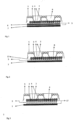
- Fig. 2 shows a double layer, 2-layered structure in which the membrane is replaced by a poly urethane (PUR) finish or coating 17 which is applied on the bottom side 2 of the double knitted structure.
- PUR poly urethane
- This PUR layer blocks water, but ensures water vapour and gas transport.
- Via a dot glue coating 5 the PUR blocking layer 17 is connected again to a single knit layer 7 with low friction characteristics to ensure easy sliding on other materials and to limit shear forces.
- Fig. 3 shows a double layer, 2-layered structure in which the membrane is replaced by a PUR coating 17, which is both applied on the bottom side 2 of the double knitted structure and on the top side of the single knit layer 7.
- PUR coating 17 Block water even more efficiently, but ensure also water vapour and gas transport in case of saturation.
- the PUR blocking layers 17 are connected to each other, connecting again also the single knit layer 7 with low friction characteristics to the two layered knitted upper structure to ensure easy sliding on other materials and to limit shear forces.
- FIG. 2 Another version of this double layered circular knitted structure is not visualized but represented largely by fig. 2 .
- the membrane in the sandwich construction is replaced by a Poly Urethane (PUR) finish 17 which blocks water and liquid, but is in this embodiment not covered at the bottom side by a single knit fabric.
- PUR Poly Urethane
- Fig 4 shows a 3-dimensional drawing with a cross section of a double knit two plane 3-dimensional structure, which is one other important illustration of the invention.
- This double knit two faced structure consists of a top layer 1 consisting of smooth multifilament polymer yarns and knitted loops of the interconnecting monofilament and/or multifilament yarn 12 which are knitted to the bottom surface layer 2, which consist of similar types of multifilament yarns with a higher capillary ratio as described above.
- This two plane 3-dimensional structure is elastic in its nature due to circular knitting process resulting in knitting loops or stitches which can be elongated in 3 dimensions, but also can get a higher elasticity via the application of a small percentage in the fabric of elastomeric yarn.
- raised structure 14 and 15 can be knitted in the same process. This is done by creating a specific tuck stitch consisting of one yarn which is a tuck stitch of the same polymere yarn in the top surface, which produce one larger loop bound together by a knitting stitch giving the raised structure.
- This so called tuck stitch with raised structure looks a bit like embroidery, but is created directly in the same circular knitting process, resulting in a raised structure, with better gliding characteristics and lower friction forces than a complete flat surface.
- These raised structures on the 3-dimensional knitted are visualized in fig. 9 , 10 , 11 , and 12 . And also in figure 9 till 20.
- Fig. 5 shows a schematic 3D-drawing of a diamond shaped structure for the recessed areas 2 and raised rims 1 between the recessed diamond shaped areas 2. Every cubic 10 represents in this drawing at least one individual yarn stitch. Depending on the number of fibers per inch which is determined by the type of knitting machine the fineness and consequently the smoothness of the double knit fabric can be determined. This fineness has a range from 20-70 yarns per inch. The width of the schematically drawn rims is more than one yarn wide (represents one cubic).
- Fig. 6 shows a schematic 3D-drawing of a cross shaped structure for the recessed areas 2 and raised rims 1 between the recessed areas 2, in which every cubic also represents one yarn stitch.
- Fig. 7 shows two top views of possible raised 1 and recessed areas 2 arranged under an angle of 45 degrees to the X-Y axis of the complete bed sheet with individual squares shown in the circle indicated by number 11.
- Fig. 8 shows a sketch of an example of a possible double knit velours structure with raised areas 1 and recessed diamond or cross shaped areas 2.
- This velours structure can be used as top layer for a passive transfer layer on which the patient is lying but is not sliding during transfer, because the caregiver will pull at this transfer layer.
- Another embodiment is the use of this velours top layer with raised and recessed area as skin contact double plane layer in a three, layer structure, in which the intermediate layer can either be an extra water absorbing layer such as described in the second alinea on page 6 or a water blocking layer.
- the bottom layer of the three layer composition can be either a smooth single knit fabric, a barrier layer (PUR membrane, PUR spray or foam finish) or both.
- This velours structure can be used as top layer for a passive stay and transfer sheet, but also as a top layer for a washable underpad product with a connected intermediate water absorbing layer, such as the described knitted structure with appr. 20% cotton and 80% PET fibers, or a non-woven composition, or a super micro knitted fabric combined with viscose (80%/20%) and a waterproof, breathable membrane with backing layer.
- a connected intermediate water absorbing layer such as the described knitted structure with appr. 20% cotton and 80% PET fibers, or a non-woven composition, or a super micro knitted fabric combined with viscose (80%/20%) and a waterproof, breathable membrane with backing layer.
- Fig 9 shows a 3-dimensional drawing of the top surface and cross section of a double knit two plane 3-dimensional structure, with a top surface with honeycomb shaped raised structures 13 which act as gliding or sliding lines and which are formed by the creation of larger double knitting loops during the knitting process which result finally in the raised rim shaped structures which can have a honeycomb shape, a square or rectangular shape, a diamond shape,
- These raised honeycomb shaped or hexagonal shaped structures 13 form boundaries for recessed areas 16, which are divided by extra horizontal gliding or sliding lines 19 which can be positioned on various positions in the honeycombs 13, horizontally, vertically or under an angle to the side of the honeycomb structure 13.
- the top and bottom plane of this 3-dimensional circular knitted structure are interconnected by the monofilament yarn 12, which can also be partly multifilament yarns 12 or can consist of joining of one monofilament yarn and one multifilament yarn in every stitch together, maintaining by this a sufficient pressure distribution capacity and capillary structure and water transport capacity to the bottom plane.
- Fig 10 shows a top view of the top of a double knit two faced 3-dimensional structure, with rectangular or square shaped raised structures 14 and 15 which are formed by the creation of larger, tuck stitches or loops in the areas where a raised line has to be created during the knitting process which result finally in the raised rim shaped structures after pulling these longer knitting loops tighter to the rest of the top surface which are the recessed sections.
- the sides of the square 16 parallel to the production direction indicated by the arrow can be made of a different, thinner and a more smoother yarn to enhance the gliding characteristics.
- the top and bottom plane of this 3-dimensional circular knitted structure are interconnected by the monofilament yarns and/or multifilament yarns.
- Fig 11 shows a top view of the top of a double knit two faced 3-dimensional structure, with 45 degrees rotated rectangular or square shaped raised structures 14 and 15, relative to the production direction of the circular knitting machine, which are again formed by the creation of larger knitting loops in the areas where a raised line has to be created during the knitting process which result finally in the raised rim shaped structures after pulling these longer knitting loops tighter to the rest of the top surface which are the recessed sections.
- the top and bottom plane of this 3-dimensional circular knitted structure are interconnected by the monofilament yarns and or multifilament yarns. Via the 45 degree rotated design of figure 11 the special stitches are structured in such a way that smooth gliding properties in x and y direction are obtained.
- Fig 12 shows a top view the top surface of a double knit 3-dimensional structure with the raised rotated diamond, squares.
- the special raised stitches are structured in such a way that smooth gliding properties in x and y direction are obtained, what can be seen as innovative.
- Double knit two plane textile products have smooth gliding properties in the length but quite poor in the width, what is not acceptable for transfers and preventing of shear and friction forces on the skin.
- These diamond or 45 degrees rotated squares are combined with the feeding of a thinner multifilament yarns indicated by the texts 1 st , 2 nd , 3 rd and 4 th in fig 12 , which enables elongation and elasticity, prevent folds and wrinkles after washing etc.
- Fig 13 shows a 3-dimensional view and side view of a double knit two plane 3-dimensional structure with the raised rotated diamond, squares and the recessed lines crossing these which have been described in the text of fig 11 .
- the v-shaped monofilament or multifilament yarns connect the top and bottom surface and that on the top surface a raised structure of knitted lines in the shape of 45 degrees rotated squares have been created in the same knitting process.
- Fig 14 shows a 3-dimensional view of the top of a double knit two plane 3-dimensional structure, with honeycomb shaped raised structures 14 and 15, relative to the production direction of the circular knitting machine, which are again formed by the creation of larger knitting loops in the areas where a raised line has to be created during the knitting process which result finally in the raised rim shaped structures after pulling these longer knitting loops tighter to the rest of the top surface which are the recessed sections
- the top and bottom plane of this 3-dimensional circular knitted structure are interconnected by the monofilament yarns and or multifilament yarns.
- Fig. 15 shows a top view and also knitting pattern of the honeycomb structure on the double knit 3-dimensional structure as raised structure with a horizontal extra gliding line dividing the honeycomb in half.
- the inner side of the hexagonal, honeycomb structure 16 is the recessed area which is divided in two halves by a horizontal gliding 18 line made of two yarns in one stitch which improves the gliding and friction drastically in the width direction, perpendicular to the wales in the recessed area, which are inherently less smooth as gliding structure.
- the gliding lines 17 which are the two parallel sides of the hexagonal raised structure and which give extra low friction and gliding characteristics in the production direction of the fabric.
- the size of the hexagonal raised structures is not determined to one measure but can be in the range of 2-20 mm or even larger.
- Fig. 16 shows a top view and also knitting pattern of the honeycomb structure on the double knit 3-dimensional structure as raised structure with a horizontal extra stepped gliding lines varying from vertical position starting either at the edges of the honeycomb and a halfway dividing position.
- stepped gliding lines 19, 20, 21 in the width direction of the fabric, which are perpendicular to the less smooth wales of the fabric, creating by this a lower friction gliding structure.
- the raised gliding lines 19, 20, 21, but the raised lines 22 and 23 also consist of either of a series of wales, a series of stitches or of a combination of both.
- Each stitch or wale consists of a tuck stitch consisting of a longer loop of a tuck stitch knitted together with a knitting stitch, which results in a raised surface above the standard knitted top plane of the 3-dimensional knitted fabric.
- the size of the hexagonal raised structures is not restricted to one measure but can be in the range of 5-20 mm or even larger.
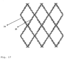
- Fig. 17 shows a top view and also knitting pattern of a small diamond structure on the double knit 3-dimensional structure as raised structure interconnected to each other.
- the smaller raised diamond structures have dimensions of 5-10 mm and enhance the gliding characteristics enormously in all directions.
- Fig. 18 shows a 3-dimensional drawing of the raised structure of fig. 16 , on the knitted top plane 1, interconnected via the intermediate section with monofilament and or multifilament yarns 12 to a bottom plane 2 in one integral 3-dimensional double knit structure.
- One can clearly identify on the top plane 1 three raised or stepped horizontal gliding lines 19, 20, 21 lines, which have been created by the same type of long tuck stitches technique such as the raised sides 22 and 23 of the honeycomb structure, consisting of a double knitting stitch and loop, resulting in higher, raised surface of these lines or sides.
- Fig. 19 shows a raised structure pattern of interconnected circular elements, which can also be oval of shape and which can be created by the sample of knitting technique as the honeycomb structures of fig , 9 , 15 , 16 , 18 .
- Fig. 20 shows a raised structure pattern of interconnected octagonal and square elements, which can be created by the sample of knitting technique as the honeycomb structures of fig. 4 9 , 15,16 , 18 , 20 .
- Fig 21 shows a 3-dimensional sketch of the possible use of the permanent active stay and transfer layer 2 which stays underneath the patient and covers the spacer fabric and or foam mattress.
- This active stay and transfer layer is elastic, doesn't enhance pressures, shear forces and limits frictions. Due to the smooth and low friction characteristics as described in the various embodiments above the patient can be pulled and slide over the top surface layer of this active stay and transfer sheet to the side of the bed or other edges for transfers out of bed and repositioning of them.
- the passive stay and transfer sheet 3 which is used to pull at and has a limited elasticity.
- the passive stay and transfer sheet 3 can be a single knit on both sides smooth fabric and can be connected to the active stay and transfer sheet 2.
- this passive transfer and stay sheet is a version which can stay underneath the more immobile patients permanently or can be positioned underneath them and which has a limited elasticity, a high water absorption capacity and water blocking layer as described in the configurations of fig. 1, 2, 3 or 4 .
- the top layer is a double knit elastic layer with raised and recessed areas, either a jacquard knitted two plane layer or a double knit two plane 3-dimensional structure and this layer can be glued via dot coating technique to another membrane type of layer or can itself be treated in such a way that leakage to the underlying mattress is prevented by applying a sprayed or foamed PUR coating to the bottom plane of the double knit fabric and or non-sliding, glueing side of the single knit layer.
- An inelastic transfer sheet is needed in order to transfer an immobile patient together with the sheet.
- the inelasticity is to assure efficient transport by nursing staff.
- the top surface being a double knitted textile fabric is dot coated with elastic Hotmelt glue to a PU membrane film blocking water but which is breathable and is allowing vapours and gases to go through.
- This composition of 2 layers is then dot glue coated (with PU) to a low friction bottom surface, preferably a smooth, low friction single knit fabric of PET-fibers that is guaranteeing low friction transfer, sliding and limits the shear forces drastically.
- the PU membrane is normally composed of a micro porous film and in this version foreseen with a monolithic membrane that ensures continuous breathability and has limited elasticity.
- the amount of glue used will limit the overall elasticity in the both horizontal directions of the 3-layer passive transfer and stay sheet and will allow direct pulling and sliding of this sheet on the underlying materials when the patient is on it.
- a special configuration of this passive stay and transfer sheet can be a version which has due to its double knitted structure and number of filaments of fibers, extra moisture absorption capacity for persons who sweat more than moderate or suffer from urine overflow from their incontinence diapers and can be a velours structure with raised and recessed areas or a double knitted two plane structure made of a combination of the last one with a velours layer as described or a two layer double knit jacquard or 3-dimensionals structure with raised and recessed areas on top.
- the 1 layer passive stay and transfer double knitted textile fabric is produced on an interlock "8 lock" machine with a gauge from 28 to 48, more preferable between 36 and 44.
- the structure is composed of a 100% PET yarn with a fineness of between 50 and 150 decitex and between 40 and 120 filaments.
- the interlock knitted structure is modified in such a way that it is limiting the elasticity of the fabric in the width and longitudinal direction to such a limit that the final elasticity is between 3 and max 8%.
- An elastic transfer sheet is needed in order to enable a mobile patient to transfer himself on that sheet and/or with assistance of the nursing staff.
- the top surface being a double knitted textile fabric with two planes that is dot glue coated to a PU membrane blocking water but who is breathable and is letting vapours and gases go through.
- This PU membrane is dot coated to a low friction bottom surface/backing that is ensuring the protection of the monolithic or polymer membrane and which is preferably an elastic single knit fabric of PET-fibers.
- the top surface being a double knitted textile fabric is dot glue coated to a low friction bottom single knit surface to guarantee low shear forces of the stay and transfer sheet on the underlying materials.
- This low friction bottom surface is treated with a breathable water repellent finish such as PUR finish, a FluorCarbon C6 finish, a dendrimer based finish or a silicone polymer finish and or a membrane, of which the PUR spray or foam finish can be applied on the bottom side of the two plane fabric and on the top side of the single knit fabric enabling a higher barrier function for water vapour.
- the top surface being a double knitted textile fabric that is dot glue coated to an elastic single/double knit backing.
- This surface or surfaces can be provided with a breathable water repellent finish and or membrane such as described.
- the permanent active and or passive stay and transfer sheet will consist of a special 3-dimensional double knitted spacer fabric in which top and bottom layers are interconnected through monofilament and or multifilament fibers.
- the top and bottom layer are very soft and have low friction properties and have different fiber composition with a lower number of filaments on top than at the bottom and an equal or higher single filament diameter at the top surface.
- a raised structure is created in the (circular) knitting process by the creation of tuck stitches, which are 2-3 times longer than the regular knitting loops of the multifilament fiber and which are pulled tighter creating a raised rim or line.
- the bottom layer of this version but also of configurations a, b, c, d can be produced with the laminating/ coating of a monolithic membrane or special membranes/finishes as described below.
- the top layer has a mini raised grid structure with raised and recessed areas to reduce skin frictions. Between the top- and under layer small also square, rectangular or diamond shaped sections of monofils can be produced that are surrounded on all sides with open areas without monofils, which result in better tri axial elastic, elongation and independent resilience properties.
- the bottom layer has a structure of smooth non texturized fibers so that it can distribute pressure forces to the under laying mattress structures.
- Another version for use in the invention is in x and y directions elastic cover sheet with a smooth top layer and breathable membrane layer beneath it, serving as cover for the Mini matrass and allowing the stay and transfer sheet to reduce the shear and friction forces that occur when the patient is laying on it.
- the top layer of the coversheet is produced on a single knit machine with a gauge between 22 till 44 more preferable between 26 till 36- This single knit is based on a pique structure is made from PET yarns and specific percentage of elastomeric yarns and is dot coated to a breathable PU membrane between 10 and 40 micron meter thick..
- the composition assures protection of the mini matrass and allowing ventilation of vapours and through its elasticity enhances the pressure reduction process.
- barrier layer is made from an open single knit PET structure, which is very smooth and foreseen with a PU finish or dendrimer based finish or coating, which can fulfil a function as a barrier and gliding layer
- Single plane circular knitted passive stay and transfer layer consisting of a double knit circular knitted fabric with limited elasticity via the so called interlock system and with raised lines or surfaces on top and or bottom surface. Both sides of the product are knitted with a very smooth PET yarn.
- the invention proposes a smart textile solution to facilitate permanent and long time staying in wheelchairs, chairs and on beds of chronically ill, less mobile and immobile patients especially in the elderly care, nursery care, rehabilitation and homecare in the embodiment of a textile based stretchable stay and transfer layer which can cover mattresses and cushions.
- Technical solutions within the invention are provided to guarantee a dry skin and to control the temperature thereof, the so called control of the micro climate, to lower and evenly distribute pressures and shear forces, and moreover to enable an easy low friction movement of patients in bed or in sitting positions, and to enable transfers into the bed and transfers out of the bed.
Landscapes
- Health & Medical Sciences (AREA)
- Nursing (AREA)
- Life Sciences & Earth Sciences (AREA)
- Animal Behavior & Ethology (AREA)
- General Health & Medical Sciences (AREA)
- Public Health (AREA)
- Veterinary Medicine (AREA)
- Engineering & Computer Science (AREA)
- Textile Engineering (AREA)
- Knitting Of Fabric (AREA)
- Invalid Beds And Related Equipment (AREA)
Claims (27)
- Drap de repos et de transfert extensible destiné à être utilisé sur des matelas, des surmatelas, des coussins de fauteuil roulant, des tables d'opération, etc. pour une personne couchée ou assise dessus, comprenant un tissu tricoté présentant une surface extérieure pouvant entrer en contact avec l'utilisateur, dans lequel :- la surface extérieure comprend des zones en relief (1) et en creux (2) sur un plan supérieur de ladite surface qui sont formées par des mailles et sont agencées selon un motif prédéterminé apte à diminuer et à répartir les forces de frottement avec un utilisateur soutenu sur la surface extérieure, ledit motif comprenant des zones en relief (1, 14, 15, 17, 18, 19, 20, 21, 22, 23), caractérisé en ce que lesdites zones en relief (1, 14, 15, 17, 18, 19, 20, 21, 22, 23) ont une dimension de plus d'une seule maille dans une direction de ses rangées de mailles et de ses colonnes de mailles, respectivement,- des zones en relief du motif sont sous la forme de lignes en relief (1, 14, 15, 17, 18, 19, 20, 21, 22, 23) pouvant entrer en contact avec l'utilisateur en bandes ou en rubans pour un utilisateur soutenu sur la surface extérieure,- des zones en creux (2, 16) ont une forme sélectionnée dans le groupe constitué des formes carrées, rectangulaires, hexagonales, octogonales, polygonales, en nid d'abeilles, circulaires, ovales, en losange, en croix, et irrégulières, et sont entourées par des lignes en relief (1, 14, 15, 17, 18, 19, 20, 21, 22, 23) en bandes ou en rubans formant des pourtours desdites zones en creux (2, 16) et étant interconnectées les unes aux autres pour créer des lignes en relief (1, 14, 15, 17, 18, 19, 20, 21, 22, 23) s'étendant sur une dimension de longueur et/ou de largeur du tissu.
- Drap extensible selon la revendication 1, caractérisé en ce que le tissu inclut du fil élastique pour augmenter l'élasticité du tissu.
- Drap extensible selon la revendication 1 ou 2, caractérisé en ce qu'il comprend un tissu tricoté double ayant une couche supérieure et une couche inférieure reliée à celle-ci par du fil (12) s'étendant entre les deux couches, et dans lequel la couche supérieure comprend la surface extérieure pouvant entrer en contact avec l'utilisateur et au moins la couche supérieure inclut du fil élastique.
- Drap extensible selon n'importe laquelle des revendications précédentes, caractérisé en ce que les lignes en relief (22, 23) sont continues au moins sur la longueur du tissu.
- Drap extensible selon n'importe laquelle des revendications précédentes, caractérisé en ce que le motif comprend des lignes en relief (17) qui sont orientées dans une direction générale des colonnes de mailles du tissu.
- Drap extensible selon n'importe laquelle des revendications précédentes, caractérisé en ce que le motif comprend des lignes en relief (18) qui sont orientées dans une direction générale des rangées de mailles du tissu.
- Drap extensible selon n'importe laquelle des revendications précédentes, caractérisé en ce que le motif comprend des lignes en relief (23) qui sont orientées obliquement par rapport aux rangées et aux colonnes de mailles.
- Drap extensible selon n'importe laquelle des revendications précédentes, caractérisé en ce que les zones en relief (1) comprennent des mailles ayant de plus longues boucles de fil dressées que des mailles formant des zones en creux (2) adjacentes.
- Drap extensible selon n'importe laquelle des revendications précédentes, caractérisé en ce que les zones en relief (1) comprennent des mailles chargées.
- Drap extensible selon n'importe laquelle des revendications précédentes 3 à 9, caractérisé en ce que la couche supérieure et la couche inférieure comprennent des fils multifilaments, le diamètre des filaments du fil tricoté dans la couche supérieure étant égal ou supérieur au diamètre des filaments du fil tricoté dans la couche inférieure.
- Drap extensible selon n'importe laquelle des revendications précédentes 3 à 9, caractérisé en ce que la couche supérieure et la couche inférieure comprennent des fils multifilaments, le nombre de filaments du fil tricoté dans la couche supérieure étant égal ou inférieur au nombre de filaments du fil tricoté dans la couche inférieure.
- Drap extensible selon n'importe laquelle des revendications précédentes 3 à 11, caractérisé en ce que la couche supérieure et la couche inférieure comprennent des fils élastiques, le diamètre et la résilience du fil élastique tricoté dans la couche supérieure étant plus grands que le diamètre et la résilience du fil tricoté dans la couche inférieure.
- Drap extensible selon n'importe laquelle des revendications précédentes 3 à 11, caractérisé en ce que la couche supérieure et la couche inférieure comprennent des fils élastiques, le diamètre et la résilience du fil élastique tricoté dans la couche supérieure étant inférieurs au diamètre et à la résilience du fil tricoté dans la couche inférieure.
- Drap extensible selon la revendication 13, caractérisé en ce que dans un état non étiré, le nombre de mailles par cm2 est de 50 % à 100 % plus élevé dans la couche inférieure que dans la couche supérieure.
- Drap extensible selon n'importe laquelle des revendications précédentes 3 à 14, caractérisé en ce que les fils tricotés dans la couche supérieure sont sélectionnés dans le groupe constitué de : PES, PET, PTFE, UHMPE, PA, tous ces fils étant texturés ou non texturés.
- Drap extensible selon la revendication 15, caractérisé en ce que la couche supérieure comprend seulement du fil non texturé et la couche inférieure comprend du fil texturé.
- Drap extensible selon la revendication 15, caractérisé en ce qu'au moins un des fils est revêtu d'un apprêt en polymère à faible friction.
- Drap extensible selon les revendications précédentes 3 à 17, caractérisé en ce que la couche inférieure présente une surface extérieure lisse.
- Drap extensible selon les revendications précédentes 3 à 17, caractérisé en ce que la couche inférieure comprend des zones en relief (1) et en creux (2) sur sa surface extérieure.
- Drap extensible selon la revendication 3, caractérisé en ce qu'il comprend une couche barrière à l'eau et/ou une couche perméable aux gaz et à la vapeur (6, 17) agencées sur la surface extérieure de la couche inférieure.
- Drap extensible selon la revendication 20, caractérisé en ce qu'il comprend une membrane (6) jouant le rôle de couche barrière à l'eau et/ou de couche perméable aux gaz et à la vapeur.
- Drap extensible selon la revendication 3, caractérisé en ce qu'il comprend une couche de polyuréthane (17) appliquée sur la surface extérieure de la couche inférieure ou sur des moyens attachés à celle-ci.
- Drap extensible selon la revendication 3, caractérisé en ce qu'une couche d'apprêt en dendrimère est appliquée sur la surface extérieure de la couche inférieure ou sur des moyens attachés à celle-ci pour la rendre hydrophobe.
- Drap extensible selon les revendications 22 et 23, caractérisé en ce que la couche de polyuréthane et/ou l'apprêt en dendrimère sont recouverts d'une couche de tissu élastique tricoté simple (7) qui est attachée à ceux-ci.
- Drap extensible selon n'importe laquelle des revendications précédentes 3 à 24, caractérisé en ce que le tissu tricoté double face est un tissu d'espacement tridimensionnel ayant des fils d'espacement monofilaments ou multifilaments (12) entre la couche supérieure et la couche inférieure.
- Drap extensible selon n'importe laquelle des revendications 3 à 25, caractérisé en ce que le tissu tricoté double face est un tissu Jacquard.
- Tissu extensible selon n'importe laquelle des revendications précédentes, caractérisé en ce que les zones en relief (1) sont fabriquées du même type de fibres que les zones en creux (2).
Applications Claiming Priority (1)
| Application Number | Priority Date | Filing Date | Title |
|---|---|---|---|
| NL1040582 | 2013-12-31 |
Publications (2)
| Publication Number | Publication Date |
|---|---|
| EP2921579A1 EP2921579A1 (fr) | 2015-09-23 |
| EP2921579B1 true EP2921579B1 (fr) | 2024-07-31 |
Family
ID=51022952
Family Applications (1)
| Application Number | Title | Priority Date | Filing Date |
|---|---|---|---|
| EP14200617.0A Active EP2921579B1 (fr) | 2013-12-31 | 2014-12-30 | Support textile étirable et feuille de transfert |
Country Status (4)
| Country | Link |
|---|---|
| US (1) | US10781541B2 (fr) |
| EP (1) | EP2921579B1 (fr) |
| CA (1) | CA2935424C (fr) |
| WO (1) | WO2015101631A1 (fr) |
Families Citing this family (25)
| Publication number | Priority date | Publication date | Assignee | Title |
|---|---|---|---|---|
| DE202015008053U1 (de) * | 2015-11-24 | 2016-02-23 | bett1.de GmbH | Matratzenbezug |
| DE102016005593A1 (de) * | 2016-05-10 | 2017-11-16 | Ulmer Strickdesign GmbH | Formmaschenware mit 3D-Oberflächenstruktur |
| US11304536B2 (en) * | 2016-07-28 | 2022-04-19 | Airweave Inc. | Bedding and bedding cover sheet |
| US11246775B2 (en) | 2017-12-28 | 2022-02-15 | Stryker Corporation | Patient turning device for a patient support apparatus |
| US11173085B2 (en) | 2017-12-28 | 2021-11-16 | Stryker Corporation | Mattress cover for a mattress providing rotation therapy to a patient |
| WO2019199812A1 (fr) * | 2018-04-13 | 2019-10-17 | Nike Innovate C.V. | Composant tricoté à rembourrage incrusté |
| USD888963S1 (en) | 2018-09-28 | 2020-06-30 | Stryker Corporation | Cover assembly for a patient support |
| USD901940S1 (en) | 2018-09-28 | 2020-11-17 | Stryker Corporation | Patient support |
| USD888962S1 (en) | 2018-09-28 | 2020-06-30 | Stryker Corporation | Cover assembly for a patient support |
| USD879966S1 (en) | 2018-09-28 | 2020-03-31 | Stryker Corporation | Crib assembly |
| USD977109S1 (en) | 2018-09-28 | 2023-01-31 | Stryker Corporation | Crib assembly for a patient support |
| USD877915S1 (en) | 2018-09-28 | 2020-03-10 | Stryker Corporation | Crib assembly |
| USD888964S1 (en) | 2018-09-28 | 2020-06-30 | Stryker Corporation | Crib assembly for a patient support |
| USD894223S1 (en) | 2018-10-31 | 2020-08-25 | Stryker Corporation | Display screen with animated graphical user interface |
| USD890914S1 (en) | 2018-10-31 | 2020-07-21 | Stryker Corporation | Pump |
| USD892159S1 (en) | 2018-10-31 | 2020-08-04 | Stryker Corporation | Display screen with animated graphical user interface |
| USD894957S1 (en) | 2018-10-31 | 2020-09-01 | Stryker Corporation | Display screen or portion thereof with graphical user interface |
| USD894226S1 (en) | 2018-10-31 | 2020-08-25 | Stryker Corporation | Display screen or portion thereof with graphical user interface |
| USD894956S1 (en) | 2018-10-31 | 2020-09-01 | Stryker Corporation | Display screen or portion thereof with graphical user interface |
| USD893543S1 (en) | 2018-10-31 | 2020-08-18 | Stryker Corporation | Display screen with graphical user interface |
| CN110592789B (zh) * | 2019-10-12 | 2020-10-16 | 珠海建轩服装有限公司 | 空气层面料、空气层提花面料及其编织方法 |
| CN115768508A (zh) * | 2020-04-07 | 2023-03-07 | 瑞思迈亚洲私人有限公司 | 具有硅酮层的织物密封 |
| US20220064825A1 (en) * | 2020-09-01 | 2022-03-03 | Casper Sleep Inc. | Light woven sheet |
| CN113151959B (zh) * | 2021-04-30 | 2022-12-06 | 福建华峰新材料有限公司 | 一种具有松紧效果的压缩布料及其生产方法 |
| EP4402311A1 (fr) * | 2021-09-14 | 2024-07-24 | NIKE Innovate C.V. | Éléments et articles tricotés pour une meilleure maîtrise du ballon et une meilleure durabilité |
Family Cites Families (26)
| Publication number | Priority date | Publication date | Assignee | Title |
|---|---|---|---|---|
| US3971234A (en) | 1974-09-04 | 1976-07-27 | E. I. Du Pont De Nemours And Company | Double-knit elastic fabric with raised patterns |
| JPS5369586U (fr) * | 1976-10-18 | 1978-06-10 | ||
| US4572174A (en) | 1983-11-22 | 1986-02-25 | Kasriel Eilender | Low friction bed pad |
| US5013089A (en) * | 1989-09-15 | 1991-05-07 | General Motors Corporation | Thin profile integrated suspension and seat trim cover |
| US5422153A (en) * | 1993-06-25 | 1995-06-06 | Marumiya Shoko Co., Ltd. | Weft knitted composite fabric |
| US5735145A (en) | 1996-05-20 | 1998-04-07 | Monarch Knitting Machinery Corporation | Weft knit wicking fabric and method of making same |
| FR2749327B1 (fr) * | 1996-06-04 | 1998-06-26 | Commissariat Energie Atomique | Structure textile tricotee a double peau et fils de liaison orientable et son procede de fabrication |
| CA2223120C (fr) | 1997-12-02 | 2002-02-12 | Vintex Inc. | Tissu textile |
| US6311525B1 (en) | 2000-07-18 | 2001-11-06 | Domestic Fabrics Corporation | Non-run fitted bed sheet |
| US6300525B1 (en) | 2000-09-01 | 2001-10-09 | Milliken & Company | Method of producing fluorinated and chlorinated benzaldehydes and compositions thereof |
| US6519979B2 (en) | 2001-02-22 | 2003-02-18 | Stanton A. Freedman | Ottoman ribbed effect fabric using core spun elastomeric yarn and other fibers |
| US7235504B2 (en) * | 2001-09-28 | 2007-06-26 | Seiren Co., Ltd. | Three dimensional knitted fabric having unevenness |
| KR100596118B1 (ko) * | 2001-10-31 | 2006-07-06 | 아사히 가세이 셍이 가부시키가이샤 | 다층 구조를 갖는 탄성 편물, 성형 의류, 탄성 환편물의 제조방법, 탄성 편물의 제조방법 및 실 공급장치 |
| CA2363425A1 (fr) * | 2001-11-20 | 2003-05-20 | Francois Masse | Tissu a construction tricot |
| DE20309796U1 (de) * | 2002-06-25 | 2003-10-02 | Bodet & Horst Gmbh & Co Kg | Elastischer Matratzenbezug |
| US6755052B1 (en) * | 2003-01-16 | 2004-06-29 | Ronald M. Sytz | Knitted stretch spacer material and method of making |
| US7465683B2 (en) * | 2003-11-24 | 2008-12-16 | Mcmurray Brian L | Functional double-faced performance warp knit fabric, method of manufacturing, and products made there from |
| US7707857B1 (en) * | 2005-10-13 | 2010-05-04 | Mcmurray Fabrics, Inc. | Double faced weft-knit textile article |
| US7552604B1 (en) * | 2008-04-09 | 2009-06-30 | Milliken & Company | Double needle bar elastomeric spacer knit |
| US7849533B1 (en) | 2009-09-30 | 2010-12-14 | Hill-Rom Services, Inc. | Occupant transfer sheet |
| WO2011064796A1 (fr) | 2009-11-24 | 2011-06-03 | Stanford India Biodesign Centre | Plaque de transfert |
| US8448475B2 (en) * | 2010-04-09 | 2013-05-28 | Seiren Co., Ltd. | Skin material for interior material |
| DE202010005217U1 (de) | 2010-04-16 | 2010-08-19 | Bodet & Horst Gmbh & Co. Kg | Verbundstoff |
| WO2012162540A1 (fr) * | 2011-05-24 | 2012-11-29 | Lee David E | Tissus tricotés et procédés de fabrication associés |
| CH705247A1 (de) | 2011-07-13 | 2013-01-15 | Schoeller Textil Ag | Textiles Flächengebilde. |
| WO2015149304A1 (fr) * | 2014-04-02 | 2015-10-08 | 莆田市华峰工贸有限公司 | Procédé de préparation pour tissu à mailles en jacquard sandwich ayant deux couleurs sur une surface |
-
2014
- 2014-12-30 EP EP14200617.0A patent/EP2921579B1/fr active Active
- 2014-12-30 US US15/109,057 patent/US10781541B2/en active Active
- 2014-12-30 WO PCT/EP2014/079463 patent/WO2015101631A1/fr active Application Filing
- 2014-12-30 CA CA2935424A patent/CA2935424C/fr active Active
Also Published As
| Publication number | Publication date |
|---|---|
| US20160326674A1 (en) | 2016-11-10 |
| EP2921579A1 (fr) | 2015-09-23 |
| US10781541B2 (en) | 2020-09-22 |
| CA2935424A1 (fr) | 2015-07-09 |
| WO2015101631A1 (fr) | 2015-07-09 |
| CA2935424C (fr) | 2021-11-02 |
Similar Documents
| Publication | Publication Date | Title |
|---|---|---|
| EP2921579B1 (fr) | Support textile étirable et feuille de transfert | |
| JP5197382B2 (ja) | 粘弾性発泡体マットレス用の被覆 | |
| KR100217976B1 (ko) | 완충 구조물 | |
| EP2918715B1 (fr) | Tissu d'espacement textile tricoté en chaîne en trois dimensions et son utilisation en tant que mini matelas empêchant une escarre de décubitus | |
| US20110092935A1 (en) | Fabric liner for skin-contacting items | |
| US6028241A (en) | Patient underpad | |
| US20090312684A1 (en) | Underpad for preventing and reducing skin wounds | |
| CA2898383C (fr) | Combinaison vetement et housse d'assistance a la mobilite d'un utilisateur | |
| CN104887406A (zh) | 一种移床型隔尿垫 | |
| CA2754068C (fr) | Tissu perfectionne pour empecher et reduire les blessures cutanees | |
| Davies | Use of knitted spacer fabrics for hygiene applications | |
| JP3790856B2 (ja) | クッション材及びこれを使用した床ずれ防止マット | |
| Snycerski et al. | A functional woven fabric with controlled friction coefficients preventing bedsores | |
| JP3017588U (ja) | 寝装具 | |
| KR200383286Y1 (ko) | 흡수, 함수 기능을 갖는 경편직물 | |
| WO2024128982A1 (fr) | Tissu absorbant | |
| CA2984231A1 (fr) | Tissu multicouche | |
| EA046590B1 (ru) | Чехол для матрасов или подушек | |
| JPH09276339A (ja) | 床ずれ防止マット | |
| JPH0728533U (ja) | 褥瘡防止マット | |
| AU2013200461A1 (en) | Improved fabric for preventing and reducing skin wounds |
Legal Events
| Date | Code | Title | Description |
|---|---|---|---|
| PUAI | Public reference made under article 153(3) epc to a published international application that has entered the european phase |
Free format text: ORIGINAL CODE: 0009012 |
|
| AK | Designated contracting states |
Kind code of ref document: A1 Designated state(s): AL AT BE BG CH CY CZ DE DK EE ES FI FR GB GR HR HU IE IS IT LI LT LU LV MC MK MT NL NO PL PT RO RS SE SI SK SM TR |
|
| AX | Request for extension of the european patent |
Extension state: BA ME |
|
| 17P | Request for examination filed |
Effective date: 20160315 |
|
| RBV | Designated contracting states (corrected) |
Designated state(s): AL AT BE BG CH CY CZ DE DK EE ES FI FR GB GR HR HU IE IS IT LI LT LU LV MC MK MT NL NO PL PT RO RS SE SI SK SM TR |
|
| STAA | Information on the status of an ep patent application or granted ep patent |
Free format text: STATUS: EXAMINATION IS IN PROGRESS |
|
| 17Q | First examination report despatched |
Effective date: 20190906 |
|
| STAA | Information on the status of an ep patent application or granted ep patent |
Free format text: STATUS: EXAMINATION IS IN PROGRESS |
|
| STAA | Information on the status of an ep patent application or granted ep patent |
Free format text: STATUS: EXAMINATION IS IN PROGRESS |
|
| GRAP | Despatch of communication of intention to grant a patent |
Free format text: ORIGINAL CODE: EPIDOSNIGR1 |
|
| STAA | Information on the status of an ep patent application or granted ep patent |
Free format text: STATUS: GRANT OF PATENT IS INTENDED |
|
| RIC1 | Information provided on ipc code assigned before grant |
Ipc: A61G 7/10 20060101ALN20240215BHEP Ipc: D04B 1/18 20060101AFI20240215BHEP |
|
| RIC1 | Information provided on ipc code assigned before grant |
Ipc: A61G 7/10 20060101ALN20240221BHEP Ipc: D04B 1/18 20060101AFI20240221BHEP |
|
| INTG | Intention to grant announced |
Effective date: 20240305 |
|
| GRAS | Grant fee paid |
Free format text: ORIGINAL CODE: EPIDOSNIGR3 |
|
| GRAA | (expected) grant |
Free format text: ORIGINAL CODE: 0009210 |
|
| STAA | Information on the status of an ep patent application or granted ep patent |
Free format text: STATUS: THE PATENT HAS BEEN GRANTED |
|
| AK | Designated contracting states |
Kind code of ref document: B1 Designated state(s): AL AT BE BG CH CY CZ DE DK EE ES FI FR GB GR HR HU IE IS IT LI LT LU LV MC MK MT NL NO PL PT RO RS SE SI SK SM TR |
|
| REG | Reference to a national code |
Ref country code: CH Ref legal event code: EP Ref country code: GB Ref legal event code: FG4D |
|
| REG | Reference to a national code |
Ref country code: DE Ref legal event code: R096 Ref document number: 602014090603 Country of ref document: DE |
|
| REG | Reference to a national code |
Ref country code: IE Ref legal event code: FG4D |