EP2921028B1 - Pilot signal configuration method and associated wireless network node - Google Patents
Pilot signal configuration method and associated wireless network node Download PDFInfo
- Publication number
- EP2921028B1 EP2921028B1 EP13854869.8A EP13854869A EP2921028B1 EP 2921028 B1 EP2921028 B1 EP 2921028B1 EP 13854869 A EP13854869 A EP 13854869A EP 2921028 B1 EP2921028 B1 EP 2921028B1
- Authority
- EP
- European Patent Office
- Prior art keywords
- pilot signal
- dedicated pilot
- trp
- trps
- dedicated
- Prior art date
- Legal status (The legal status is an assumption and is not a legal conclusion. Google has not performed a legal analysis and makes no representation as to the accuracy of the status listed.)
- Active
Links
Images


Classifications
-
- H—ELECTRICITY
- H04—ELECTRIC COMMUNICATION TECHNIQUE
- H04L—TRANSMISSION OF DIGITAL INFORMATION, e.g. TELEGRAPHIC COMMUNICATION
- H04L5/00—Arrangements affording multiple use of the transmission path
- H04L5/003—Arrangements for allocating sub-channels of the transmission path
- H04L5/0048—Allocation of pilot signals, i.e. of signals known to the receiver
- H04L5/0051—Allocation of pilot signals, i.e. of signals known to the receiver of dedicated pilots, i.e. pilots destined for a single user or terminal
-
- H—ELECTRICITY
- H04—ELECTRIC COMMUNICATION TECHNIQUE
- H04W—WIRELESS COMMUNICATION NETWORKS
- H04W48/00—Access restriction; Network selection; Access point selection
- H04W48/08—Access restriction or access information delivery, e.g. discovery data delivery
- H04W48/12—Access restriction or access information delivery, e.g. discovery data delivery using downlink control channel
-
- H—ELECTRICITY
- H04—ELECTRIC COMMUNICATION TECHNIQUE
- H04W—WIRELESS COMMUNICATION NETWORKS
- H04W64/00—Locating users or terminals or network equipment for network management purposes, e.g. mobility management
Definitions
- the present disclosure generally relates to configuration and use of pilot signal, and particularly, to a pilot signal configuration method, an associated wireless network node, a pilot-signal-based reception method, and an associated user equipment (UE).
- UE user equipment
- LPNs low-power nodes
- a network consisting of traditional macro NodeBs and LPNs is referred to as a heterogeneous network.
- Two use-cases for heterogeneous network deployment that may be envisioned are coverage holes and localized traffic hotspots. Deployment of LPNs as a complement to a macro network then aims at improving coverage and capacity, respectively.
- an LPN can either form a separate cell (such as, a pico cell or a micro cell) by itself or be one of the spatially separated Transmit-Receive Points (TRPs) in one logical cell.
- TRPs Transmit-Receive Points
- the former case is referred to as separated-cell scenario, while the latter case is referred to as combined-cell (or shared-cell) scenario.
- US 2012/281554 A1 describes a method for transmitting control information in a telecommunications cell.
- TSG-RAN Technical Specification Group-Radio Access Network
- SI Technical Specification Group-Radio Access Network
- UMTS Universal Mobile Telecommunications System
- 3GPP Rel-12 3 rd Partnership Project
- An object of the present embodiments is to facilitate simultaneous transmissions to more than one UEs from selected TRPs in the proximity of the UEs within the same combined cell by providing a novel pilot signal configuration method, an associated wireless network node, a pilot-signal-based reception method and an associated UE.
- a pilot signal configuration method performed by a wireless network node in a wireless communication system.
- the method comprises allocating a dedicated pilot signal to a UE within a combined cell.
- the combined cell comprises spatially separated Transmit-Receive Points, TRPs, in one logical cell, and the dedicated pilot signal is a dedicated pilot signal exclusively used by the UE or a dedicated pilot signal shared by multiple UEs, based on moving speed and/or data rate of the UE.
- the method also comprises selecting, from all TRPs within the combined cell, at least one TRP in the proximity of the UE for transmission of the dedicated pilot signal to the UE. Further, the at least one TRP is in the proximity of the UE when the distance from the at least one TRP to the UE is lower than a certain length.
- a wireless network node comprising a pilot allocation unit configured to allocate a dedicated pilot signal to a UE within a combined cell.
- the combined cell comprises spatially separated Transmit-Receive Points, TRPs, in one logical cell, and the dedicated pilot signal is a dedicated pilot signal exclusively used by the UE or a dedicated pilot signal shared by multiple UEs, based on moving speed and/or data rate of the UE.
- the wireless network node also comprises a TP selection unit configured to select, from all TRPs within the combined cell, at least one TRP in the proximity of the UE for transmission of the dedicated pilot signal to the UE. Further, the at least one TRP is in the proximity of the UE when the distance from the at least one TRP to the UE is lower than a certain length.
- a pilot-signal-based reception method performed by a UE in a wireless communication system.
- the method comprises receiving a dedicated pilot signal from at least one TRP in the proximity of a UE.
- the dedicated pilot signal is allocated to the UE within a combined cell, the combined cell comprising spatially separated TRPs in one logical cell, and the at least one TRP in the proximity of the UE is selected from all the TRPs within the combined cell for transmission of the dedicated pilot signal to the UE.
- the dedicated pilot signal is a dedicated pilot signal exclusively used by the UE or a dedicated pilot signal shared by multiple UEs, based on moving speed and/or data rate of the UE.
- the method also comprises performing channel estimation and/or demodulation based on the received dedicated pilot signal.
- a UE comprising a pilot receiving unit, a channel estimation unit and a demodulation unit.
- the pilot receiving unit is configured to receive dedicated pilot signal from at least one TRP in the proximity of the UE.
- the dedicated pilot signal is allocated to the UE within a combined cell, the combined cell comprising spatially separated TRPs in one logical cell, and the at least one TRP in the proximity of the UE is selected from all the TRPs within the combined cell for transmission of the dedicated pilot signal to the UE.
- the dedicated pilot signal is a dedicated pilot signal exclusively used by the UE or a dedicated pilot signal shared by multiple UEs, based on moving speed and/or data rate of the UE.
- the channel estimation unit is configured to perform channel estimation based on the received dedicated pilot signal.
- the demodulation unit is configured to perform demodulation based on the received dedicated pilot signal.
- the methods and devices according to the above aspects of the embodiments facilitate simultaneous transmissions to more than one UEs from selected TRPs in the proximity of the UEs within the same combined cell, which in turn allows for an increased system capacity of the combined cell.
- Fig. 1 schematically illustrates a pilot transmission scheme according to the prior art.
- four TRPs 101-104 are distributed in a combined cell 100.
- a UE 201 is geographically closest to the TRP 104, all TRPs 101-104 transmit the same Common Pilot Channel (CPICH) to the UE 201.
- CPICH Common Pilot Channel
- the UE 201 cannot estimate the single channel from the TRP 104 to itself, and thus cannot perform data reception via this channel.
- CPICH Common Pilot Channel
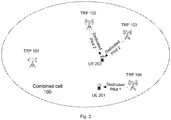
- Fig. 2 schematically illustrates a pilot transmission scheme according to the present disclosure.
- CPICH is still transmitted from all TRPs within the combined-cell 100, although it is not expressly shown for the sake of simplicity.
- dedicated pilots are newly introduced in the combined cell 100.
- a dedicated pilot is transmitted from one or more selected TRPs in the proximity of the UE.
- a dedicated pilot 1 is transmitted from TRP 104 to UE 201, and the same dedicated pilot 2 is transmitted from TRPs 102 and 103 to UE 202.
- the UE 201 can estimate the single channel from the TRP 104 to itself, so that the UE 201 can perform data transmission and reception with only one TRP (TRP 104, in this example) in its proximity within the combined cell 100.
- the UE 202 can estimate the channels from the TRPs 102 and 103 to itself, so that the UE 202 can perform data transmission and reception with more than one TRP (TRPs 102 and 103, in this example) in its proximity within the combined cell 100.
- a spatial reuse scheme i.e., simultaneous transmissions to more than one UEs from selected TRPs in the proximity of the UEs
- a SFN or a (distributed) MIMO transmission scheme i.e., transmission from more than one selected TRPs to a UE
- a SFN or a (distributed) MIMO transmission scheme i.e., transmission from more than one selected TRPs to a UE
- the SFN transmission scheme facilitated by the dedicated pilot is superior to the conventional SFN transmission scheme facilitated by the CPICH in that it avoids transmissions from remote TRPs, which make negligible contribution to the useful signal but make considerable contribution to the interference.
- a TRP is in the proximity of a UE means that the distance from the TRP to the UE is lower than a certain length. Therefore, a straightforward manner for determining whether a TRP is in the proximity of a UE is to acquire the position of the UE (for example, by requesting the UE's Global Positioning System (GPS) position from the UE), calculate the distance between the TRP and the UE based on the known position of the TRP and the acquired position of the UE, and compare the calculated distance with a prescribed length.
- GPS Global Positioning System
- the same length or different lengths may be prescribed for the TRPs.
- the length may be prescribed as the maximum of service area radii of all TRPs in the combined cell.
- various lengths may be prescribed by the network operator for different TRPs.
- instantaneous or time-average strengths of uplink control signals received at the TRPs from the UE may be employed to determine which TRP(s) within the combined cell is (are) in the proximity of the UE. Specifically, in the beginning, the TRP receiving one of the uplink control signals with the highest signal strength is determined as the optimal TRP, which is of course considered to be in the proximity of the UE. Then, it is determined whether any other TRP receives a uplink control signal with a signal strength not lower than the highest signal strength by a threshold (which is typically between 3-5 dB in logarithmic scale).
- a threshold which is typically between 3-5 dB in logarithmic scale
- the TRP is able to provide the UE with a significantly improved link quality when operating in combination with the optimal TRP, and therefore may also be determined to be in the proximity of the UE. Otherwise, only the optimal TRP is determined to be in the proximity of the UE.
- Fig. 3 is a flowchart schematically illustrating a pilot signal configuration method according to an embodiment of the present disclosure.
- a dedicated pilot signal is allocated to a UE within a combined cell (S310).
- the allocation of dedicated pilot signal can be implemented in a wireless network node, such as a RNC (Radio Network Controller), a BS (Base Station), and/or the like.
- the UE can be informed of the allocated pilot signal, for example, via RRC signalling.
- at least one TRP in the proximity of the UE is selected from all TRPs within the combined cell, for transmission of the dedicated pilot signal to the UE (S320).
- the selection of TRP can be implemented in the same wireless network node. After that, the proposed method ends.
- step S310 once the UE enters the combined cell, a dedicated pilot signal is allocated to the UE and exclusively used by the UE. This implies that the dedicated pilot signal is UE specific and will not change when the UE moves between TRPs within the combined cell.
- channel code resource dedicatedly reserved for that pilot signal. That is, when one channel code is used by a dedicated pilot, this code cannot be used for any other purpose within the same combined cell.
- the Downlink (DL) transmission becomes very similar to the Uplink (UL) transmission in the following aspects:
- One major advantage with the UE-specific dedicated pilot scheme is that the transmission/mobility handling can be transparent to the UE within one combined cell (as in UL).
- step S310 Another feasible manner to implement step S310 is to determine which UE group the UE belongs to and allocate a dedicated pilot signal shared by UEs in the UE group to the UE.
- the dedicated pilot signal is group specific. To be specific, if a UE transfers from group A to group B, it cannot use the dedicated pilot signal specific to group A anymore; instead, the dedicated pilot signal specific to group B shall be used.
- a UE may be determined as belonging to a SFN group or a non-SFN group, according to whether the UE applies the SFN transmission scheme or not applies the SFN transmission scheme.
- UEs may be grouped according to one or more of their capability, speed or the like, in addition to or instead of whether the SFN transmission scheme is applied. Specifically, in addition to or instead of whether it applies the SFN transmission scheme or not, a UE may be grouped according to whether or not it is MIMO-capable and/or which speed range its moving speed falls into.
- UEs using the same transmission scheme and/or having the same capability and/or similar moving speeds may be grouped together.
- step S320 An alternative manner to implement step S320 is to determine which area the UE is located in and allocate a dedicated pilot signal shared by UEs located in that area to the UE.
- the dedicated pilot signal is area specific. To be specific, if a UE moves from area A to area B, it cannot use the dedicated pilot signal specific to area A anymore; instead, the dedicated pilot signal specific to area B shall be used.
- an area may be covered by one TRP within a combined-cell or geographically adjacent TRPs within a combined-cell, and a UE may be determined as located in that area if it is served by any of the TRPs covering the area.
- the area may vary in shape and/or in size, according to which TRP(s) covers it.
- the geographical position of the UE may be acquired by requesting the GPS position from the UE directly or by measuring the strength of the uplink control signal from the UE and estimating the UE's position based on the measured signal strength indirectly.
- the area where a UE is located may also be considered as a factor for grouping UEs.
- UEs located in the same area and using the same transmission scheme and/or having the same capability and/or similar moving speeds may be grouped together.
- different group/area-specific dedicated pilots can be either carried on the same scrambling code or on different scrambling codes.
- different dedicated pilots are differentiated by channel codes.
- the channel codes can be either predefined or allocated dynamically. In the former case, there is no need to inform the UE of the channel codes used for the pilots, but the signalling informing the UE of the change of group/area is still required.
- different group/area-specific dedicated pilots are carried on different scrambling codes, it is preferable to have pre-defined channel codes for the pilots.
- SFN transmission occupies much more channel codes than spatial reuse. It is preferable to allocate scrambling codes respectively for spatial reuse UEs and SFN UEs, so that the channel codes occupied by SFN transmission can be freed.
- TRPs close to each other may use the same scrambling code to avoid too much inter-scrambling code interference, while TRPs far apart from each other may use different scrambling code to have more usable channel codes. In this way, a balance between channel code and power resources can be achieved.
- One major advantage with the group/area-specific dedicated pilot scheme is that the code and power consumption is relatively small.
- UE-specific dedicated pilots can be adopted for high speed UEs and/or high data rate UEs (which account for only a small fraction of all UEs in a cell and will not consume excessive resources), while group/area specific pilots can be adopted for low speed UEs with low data rate.
- UE-specific and group/area-specific pilots may be adaptively used for a UE, and the UE-specific pilot, the group/area-specific pilot and the existing CPICH may co-exist in the same combined-cell. For legacy UEs, only the existing CPICH will be used.
- the term “high speed” refers to a speed higher than or equal to 120 km/h.
- “High data rate” means that the amount of radio resources consumed by data transmission is much more than (e.g. ten times more than) the amount of radio resources consumed by control information transmission, that is, the radio resource overhead due to control information transmission is only a small fraction (e.g. low than 10%) of the total radio resource consumption.
- one common scrambling code can be adopted if the system traffic load is low (i.e., if the system is not code limited yet), while multiple different scrambling codes can be adopted if the system becomes code limited.
- the code limited scenario may happen, if, for example, there are many active LPNs and many spatial reuse and SFN UEs in one combined cell.
- dedicated pilots may be turned off.
- the ratio of legacy UEs can be calculated per TRP.
- Fig. 4 schematically illustrates a pilot-signal-based reception method according to the present disclosure.
- This method corresponds to the above-described pilot signal configuration method and is implemented at a UE.
- a dedicated pilot signal is received by the UE from at least one TRP in the proximity of the UE (S410).
- channel estimation and/or demodulation are performed based on the received dedicated pilot signal (S420).
- the proposed method ends.
- the wireless network node 500 comprises a pilot allocation unit 510 and a TRP selection unit 520.
- the pilot allocation unit 510 is configured to allocate a dedicated pilot signal to a UE within a combined cell.
- the TRP selection unit 520 is configured to select, from all TRPs within the combined cell, at least one TRP in the proximity of the UE for transmission of the dedicated pilot signal to the UE.
- the dedicated pilot signal allocated by the pilot allocation unit 510 may be exclusively used by the UE.
- the pilot allocation unit 510 may comprise a determination unit 511.
- the determination unit 511 may be configured to determine a UE group to which the UE belongs. A pilot signal shared by UEs in the UE group is allocated by the pilot allocation unit 510 to the UE as the dedicated pilot signal.
- the determination unit 511 may be configured to determine an area in which the UE is located, the area being served by one or more TRPs.
- a pilot signal shared by UEs located in the area is allocated by the pilot allocation unit 510 to the UE as the dedicated pilot signal.
- pilot allocation unit 510 and the TRP selection unit 520 may be implemented separately as suitable dedicated circuits. Nevertheless, the above-described units can also be implemented using any number of dedicated circuits through functional combination or separation. In some examples, the above-described units may be even combined in a single application specific integrated circuit (ASIC).
- ASIC application specific integrated circuit
- a wireless network node comprising a memory and a processor (including but not limited to a microprocessor, a microcontroller or a Digital Signal Processor (DSP), etc.)
- the memory stores machine-readable program code executable by the processor to control the wireless network node to perform the method as described above with reference to Fig. 3 .
- the processor may be operable to perform the functions of the pilot allocation unit 510, the determination unit 511 and the TRP selection unit 520 mentioned above.
- the UE 600 comprises a pilot receiving unit 610, a channel estimation unit 620 and a demodulation unit 630.
- the pilot receiving unit 610 is configured to receive dedicated pilot signal from at least one TRP in the proximity of a UE.
- the channel estimation unit 620 is configured to perform channel estimation based on the received dedicated pilot signal.
- the demodulation unit 630 is configured to perform demodulation based on the received dedicated pilot signal.
- the pilot receiving unit 610, the channel estimation unit 620 and the demodulation unit 630 may be implemented separately as suitable dedicated circuits. Nevertheless, the above-described units can also be implemented using any number of dedicated circuits through functional combination or separation. In some examples, the above-described units may be even combined in a single application specific integrated circuit (ASIC).
- ASIC application specific integrated circuit
- a UE comprising a memory and a processor (including but not limited to a microprocessor, a microcontroller or a Digital Signal Processor (DSP), etc.)
- the memory stores machine-readable program code executable by the processor to control the UE to perform the method as described above with respect to Fig. 4 .
- the processor may be operable to perform the functions of the pilot receiving unit 610, the channel estimation unit 620 and the demodulation unit 630 mentioned above.
- the present disclosure concerns a computer readable medium storing therein a program for a wireless network node or a UE.
- the program causes the wireless network node or the UE to perform the pilot signal configuration method or the pilot-signal-based reception method described above.
- the computer readable medium may be of any type including but not limited to a hard disk drive, a Compact Disc (CD), a Digital Video Disk (DVD), a digital tape, memory, etc.
Landscapes
- Engineering & Computer Science (AREA)
- Signal Processing (AREA)
- Computer Networks & Wireless Communication (AREA)
- Computer Security & Cryptography (AREA)
- Mobile Radio Communication Systems (AREA)
Applications Claiming Priority (2)
| Application Number | Priority Date | Filing Date | Title |
|---|---|---|---|
| CNPCT/CN2012/084573 | 2012-11-14 | ||
| PCT/CN2013/085438 WO2014075531A1 (en) | 2012-11-14 | 2013-10-18 | Pilot signal configuration method, associated wireless network node, pilot-signal-based reception method and associated user equipment |
Publications (3)
| Publication Number | Publication Date |
|---|---|
| EP2921028A1 EP2921028A1 (en) | 2015-09-23 |
| EP2921028A4 EP2921028A4 (en) | 2016-08-03 |
| EP2921028B1 true EP2921028B1 (en) | 2019-12-04 |
Family
ID=50730575
Family Applications (1)
| Application Number | Title | Priority Date | Filing Date |
|---|---|---|---|
| EP13854869.8A Active EP2921028B1 (en) | 2012-11-14 | 2013-10-18 | Pilot signal configuration method and associated wireless network node |
Country Status (4)
| Country | Link |
|---|---|
| US (1) | US9584279B2 (https=) |
| EP (1) | EP2921028B1 (https=) |
| IN (1) | IN2015DN02257A (https=) |
| WO (1) | WO2014075531A1 (https=) |
Families Citing this family (3)
| Publication number | Priority date | Publication date | Assignee | Title |
|---|---|---|---|---|
| KR102519401B1 (ko) | 2016-03-30 | 2023-04-06 | 아이디에이씨 홀딩스, 인크. | 물리적 레이어 이동성 프로시져를 수행하기 위한 방법 및 장치 |
| US11303329B2 (en) | 2016-08-11 | 2022-04-12 | Samsung Electronics Co., Ltd. | Device and system characterized by measurement, report, and change procedure by terminal for changing transmission/reception point, and base station procedure for supporting same |
| CN116915377B (zh) * | 2023-08-30 | 2024-07-19 | 江南大学 | 基于混合自动请求机制的非授权接入导频分配方法 |
Family Cites Families (16)
| Publication number | Priority date | Publication date | Assignee | Title |
|---|---|---|---|---|
| US6330460B1 (en) * | 2000-08-21 | 2001-12-11 | Metawave Communications Corporation | Simultaneous forward link beam forming and learning method for mobile high rate data traffic |
| US9240909B2 (en) * | 2008-01-24 | 2016-01-19 | Alcatel Lucent | Reverse link channel estimation using common and dedicated pilot channels |
| KR101619446B1 (ko) * | 2008-12-02 | 2016-05-10 | 엘지전자 주식회사 | 하향링크 mimo시스템에 있어서 rs 전송 방법 |
| JP5316547B2 (ja) | 2009-01-14 | 2013-10-16 | 富士通株式会社 | 装置 |
| CN102396268A (zh) * | 2009-03-04 | 2012-03-28 | 华为技术有限公司 | 一种信息发送的方法、装置和系统 |
| CN101877887B (zh) * | 2009-04-30 | 2012-12-05 | 中国移动通信集团公司 | 协作多点传输系统的下行传输控制方法和装置 |
| EP2620033B1 (en) | 2010-09-22 | 2017-09-13 | Telefonaktiebolaget LM Ericsson (publ) | Methods and arrangements for establishing a radio connection in a communication system |
| US9014020B2 (en) * | 2011-05-02 | 2015-04-21 | Blackberry Limited | Methods and systems of wireless communication with remote radio heads |
| CN103931253B (zh) * | 2011-05-03 | 2018-07-31 | 诺基亚通信公司 | 用于在混合小区标识符场景中动态分配标识符的方法和设备 |
| US8873489B2 (en) * | 2011-05-05 | 2014-10-28 | Mediatek Inc. | Signaling methods for UE-specific dynamic downlink scheduler in OFDMA systems |
| KR101741059B1 (ko) * | 2011-06-27 | 2017-06-15 | 삼성전자 주식회사 | CoMP 단말의 스케줄링 방법 및 장치 |
| CN106411489A (zh) * | 2011-08-12 | 2017-02-15 | 交互数字专利控股公司 | Wtru及用于该wtru的方法 |
| BR112014011040B1 (pt) * | 2011-11-07 | 2023-03-28 | Motorola Mobility Llc | Método e aparelho para retorno de csi para esquemas de processamento conjunto em um sistema de comunicação de multiplexação com divisão de frequência ortogonal com transmissão de ponto múltiplo coordenado |
| EP2849372A4 (en) * | 2012-05-11 | 2015-05-27 | Fujitsu Ltd | MOBILE BASE STATION AND WIRELESS COMMUNICATION PROCESS |
| CN104854800B (zh) * | 2012-10-03 | 2017-12-05 | Zte维创通讯公司 | 无线网络中的动态传输天线的重配置 |
| US8976884B2 (en) * | 2012-12-20 | 2015-03-10 | Google Technology Holdings LLC | Method and apparatus for antenna array channel feedback |
-
2013
- 2013-10-18 WO PCT/CN2013/085438 patent/WO2014075531A1/en not_active Ceased
- 2013-10-18 US US14/442,249 patent/US9584279B2/en not_active Expired - Fee Related
- 2013-10-18 EP EP13854869.8A patent/EP2921028B1/en active Active
- 2013-10-18 IN IN2257DEN2015 patent/IN2015DN02257A/en unknown
Non-Patent Citations (1)
| Title |
|---|
| None * |
Also Published As
| Publication number | Publication date |
|---|---|
| US20160197711A1 (en) | 2016-07-07 |
| US9584279B2 (en) | 2017-02-28 |
| WO2014075531A1 (en) | 2014-05-22 |
| IN2015DN02257A (https=) | 2015-08-21 |
| EP2921028A4 (en) | 2016-08-03 |
| EP2921028A1 (en) | 2015-09-23 |
Similar Documents
| Publication | Publication Date | Title |
|---|---|---|
| US10383125B2 (en) | Terminal device and wireless communication device | |
| US10749586B2 (en) | Terminal device, wireless communication device, and communication method | |
| AU2011201791B2 (en) | Wireless communication system and wireless terminal device | |
| US9961646B2 (en) | Devices and method using transmit power control and scheduling for LTE unlicensed band operation | |
| US9900132B2 (en) | Pilot signal transmission method, associated transmit-receive point, pilot signal reception method and associated user equipment | |
| KR20160026091A (ko) | 다중 셀 다중 사용자 통신 시스템에서 적응적 빔 호핑을 위한 방법 및 장치 | |
| EP2165430A2 (en) | Setting maximum power at a mobile communication system base station having multiple antennas | |
| KR102288804B1 (ko) | 무선 통신 시스템에서 안테나를 선택하기 위한 방법 및 장치 | |
| WO2020196279A1 (ja) | 通信装置、基地局装置、通信方法、及び基地局装置の制御方法 | |
| US20160057756A1 (en) | Method, network node, computer program and computer program product for combined cell | |
| EP3087790B1 (en) | Determining position of a wireless device using remote radio head devices with multiple antenna devices | |
| EP2921028B1 (en) | Pilot signal configuration method and associated wireless network node | |
| KR20160010570A (ko) | 이종 네트워크에서의 다운링크 전송 방법, 제어 디바이스, 기지국 및 이종 시스템 | |
| JPWO2019097929A1 (ja) | 端末装置、基地局、方法及び記録媒体 | |
| KR20230113187A (ko) | 빔 기반 사이드링크 통신을 위한 자원 선택 방법 및 장치 및 이를 이용한 사이드링크 통신 | |
| EP3069563B1 (en) | Port selection in combined cell of radio access network | |
| JP2014520431A (ja) | Mu−mimoの伝送方法、ユーザ装置及び基地局 | |
| US10003987B2 (en) | Method for transmitting data to a wireless device in a communications network which applies a combined cell deployment | |
| US8514784B2 (en) | Method for processing downlink signal in sector portion and base station thereof | |
| CN118265161A (zh) | 通信方法和通信装置 | |
| JP2011166505A (ja) | 無線制御装置及び無線通信方法 | |
| HK1241644A1 (en) | Devices and method using transmit power control and scheduling for lte unlicensed band operation | |
| AU2012202258A1 (en) | Wireless communication system and wireless terminal device |
Legal Events
| Date | Code | Title | Description |
|---|---|---|---|
| PUAI | Public reference made under article 153(3) epc to a published international application that has entered the european phase |
Free format text: ORIGINAL CODE: 0009012 |
|
| 17P | Request for examination filed |
Effective date: 20150326 |
|
| AK | Designated contracting states |
Kind code of ref document: A1 Designated state(s): AL AT BE BG CH CY CZ DE DK EE ES FI FR GB GR HR HU IE IS IT LI LT LU LV MC MK MT NL NO PL PT RO RS SE SI SK SM TR |
|
| AX | Request for extension of the european patent |
Extension state: BA ME |
|
| DAX | Request for extension of the european patent (deleted) | ||
| RA4 | Supplementary search report drawn up and despatched (corrected) |
Effective date: 20160701 |
|
| RIC1 | Information provided on ipc code assigned before grant |
Ipc: H04W 88/00 20090101AFI20160627BHEP |
|
| STAA | Information on the status of an ep patent application or granted ep patent |
Free format text: STATUS: EXAMINATION IS IN PROGRESS |
|
| 17Q | First examination report despatched |
Effective date: 20190226 |
|
| REG | Reference to a national code |
Ref country code: DE Ref legal event code: R079 Ref document number: 602013063736 Country of ref document: DE Free format text: PREVIOUS MAIN CLASS: H04W0088000000 Ipc: H04W0048120000 |
|
| RIC1 | Information provided on ipc code assigned before grant |
Ipc: H04L 5/00 20060101ALI20190529BHEP Ipc: H04W 48/12 20090101AFI20190529BHEP |
|
| GRAP | Despatch of communication of intention to grant a patent |
Free format text: ORIGINAL CODE: EPIDOSNIGR1 |
|
| STAA | Information on the status of an ep patent application or granted ep patent |
Free format text: STATUS: GRANT OF PATENT IS INTENDED |
|
| INTG | Intention to grant announced |
Effective date: 20190710 |
|
| GRAS | Grant fee paid |
Free format text: ORIGINAL CODE: EPIDOSNIGR3 |
|
| GRAA | (expected) grant |
Free format text: ORIGINAL CODE: 0009210 |
|
| STAA | Information on the status of an ep patent application or granted ep patent |
Free format text: STATUS: THE PATENT HAS BEEN GRANTED |
|
| AK | Designated contracting states |
Kind code of ref document: B1 Designated state(s): AL AT BE BG CH CY CZ DE DK EE ES FI FR GB GR HR HU IE IS IT LI LT LU LV MC MK MT NL NO PL PT RO RS SE SI SK SM TR |
|
| REG | Reference to a national code |
Ref country code: GB Ref legal event code: FG4D |
|
| REG | Reference to a national code |
Ref country code: CH Ref legal event code: EP |
|
| REG | Reference to a national code |
Ref country code: AT Ref legal event code: REF Ref document number: 1211114 Country of ref document: AT Kind code of ref document: T Effective date: 20191215 |
|
| REG | Reference to a national code |
Ref country code: IE Ref legal event code: FG4D |
|
| REG | Reference to a national code |
Ref country code: DE Ref legal event code: R096 Ref document number: 602013063736 Country of ref document: DE |
|
| REG | Reference to a national code |
Ref country code: NL Ref legal event code: MP Effective date: 20191204 |
|
| REG | Reference to a national code |
Ref country code: LT Ref legal event code: MG4D |
|
| PG25 | Lapsed in a contracting state [announced via postgrant information from national office to epo] |
Ref country code: NO Free format text: LAPSE BECAUSE OF FAILURE TO SUBMIT A TRANSLATION OF THE DESCRIPTION OR TO PAY THE FEE WITHIN THE PRESCRIBED TIME-LIMIT Effective date: 20200304 Ref country code: BG Free format text: LAPSE BECAUSE OF FAILURE TO SUBMIT A TRANSLATION OF THE DESCRIPTION OR TO PAY THE FEE WITHIN THE PRESCRIBED TIME-LIMIT Effective date: 20200304 Ref country code: FI Free format text: LAPSE BECAUSE OF FAILURE TO SUBMIT A TRANSLATION OF THE DESCRIPTION OR TO PAY THE FEE WITHIN THE PRESCRIBED TIME-LIMIT Effective date: 20191204 Ref country code: LT Free format text: LAPSE BECAUSE OF FAILURE TO SUBMIT A TRANSLATION OF THE DESCRIPTION OR TO PAY THE FEE WITHIN THE PRESCRIBED TIME-LIMIT Effective date: 20191204 Ref country code: GR Free format text: LAPSE BECAUSE OF FAILURE TO SUBMIT A TRANSLATION OF THE DESCRIPTION OR TO PAY THE FEE WITHIN THE PRESCRIBED TIME-LIMIT Effective date: 20200305 Ref country code: LV Free format text: LAPSE BECAUSE OF FAILURE TO SUBMIT A TRANSLATION OF THE DESCRIPTION OR TO PAY THE FEE WITHIN THE PRESCRIBED TIME-LIMIT Effective date: 20191204 Ref country code: SE Free format text: LAPSE BECAUSE OF FAILURE TO SUBMIT A TRANSLATION OF THE DESCRIPTION OR TO PAY THE FEE WITHIN THE PRESCRIBED TIME-LIMIT Effective date: 20191204 |
|
| PG25 | Lapsed in a contracting state [announced via postgrant information from national office to epo] |
Ref country code: RS Free format text: LAPSE BECAUSE OF FAILURE TO SUBMIT A TRANSLATION OF THE DESCRIPTION OR TO PAY THE FEE WITHIN THE PRESCRIBED TIME-LIMIT Effective date: 20191204 Ref country code: HR Free format text: LAPSE BECAUSE OF FAILURE TO SUBMIT A TRANSLATION OF THE DESCRIPTION OR TO PAY THE FEE WITHIN THE PRESCRIBED TIME-LIMIT Effective date: 20191204 |
|
| PG25 | Lapsed in a contracting state [announced via postgrant information from national office to epo] |
Ref country code: AL Free format text: LAPSE BECAUSE OF FAILURE TO SUBMIT A TRANSLATION OF THE DESCRIPTION OR TO PAY THE FEE WITHIN THE PRESCRIBED TIME-LIMIT Effective date: 20191204 |
|
| PG25 | Lapsed in a contracting state [announced via postgrant information from national office to epo] |
Ref country code: PT Free format text: LAPSE BECAUSE OF FAILURE TO SUBMIT A TRANSLATION OF THE DESCRIPTION OR TO PAY THE FEE WITHIN THE PRESCRIBED TIME-LIMIT Effective date: 20200429 Ref country code: ES Free format text: LAPSE BECAUSE OF FAILURE TO SUBMIT A TRANSLATION OF THE DESCRIPTION OR TO PAY THE FEE WITHIN THE PRESCRIBED TIME-LIMIT Effective date: 20191204 Ref country code: CZ Free format text: LAPSE BECAUSE OF FAILURE TO SUBMIT A TRANSLATION OF THE DESCRIPTION OR TO PAY THE FEE WITHIN THE PRESCRIBED TIME-LIMIT Effective date: 20191204 Ref country code: NL Free format text: LAPSE BECAUSE OF FAILURE TO SUBMIT A TRANSLATION OF THE DESCRIPTION OR TO PAY THE FEE WITHIN THE PRESCRIBED TIME-LIMIT Effective date: 20191204 Ref country code: RO Free format text: LAPSE BECAUSE OF FAILURE TO SUBMIT A TRANSLATION OF THE DESCRIPTION OR TO PAY THE FEE WITHIN THE PRESCRIBED TIME-LIMIT Effective date: 20191204 Ref country code: EE Free format text: LAPSE BECAUSE OF FAILURE TO SUBMIT A TRANSLATION OF THE DESCRIPTION OR TO PAY THE FEE WITHIN THE PRESCRIBED TIME-LIMIT Effective date: 20191204 |
|
| PG25 | Lapsed in a contracting state [announced via postgrant information from national office to epo] |
Ref country code: SM Free format text: LAPSE BECAUSE OF FAILURE TO SUBMIT A TRANSLATION OF THE DESCRIPTION OR TO PAY THE FEE WITHIN THE PRESCRIBED TIME-LIMIT Effective date: 20191204 Ref country code: SK Free format text: LAPSE BECAUSE OF FAILURE TO SUBMIT A TRANSLATION OF THE DESCRIPTION OR TO PAY THE FEE WITHIN THE PRESCRIBED TIME-LIMIT Effective date: 20191204 Ref country code: IS Free format text: LAPSE BECAUSE OF FAILURE TO SUBMIT A TRANSLATION OF THE DESCRIPTION OR TO PAY THE FEE WITHIN THE PRESCRIBED TIME-LIMIT Effective date: 20200404 |
|
| REG | Reference to a national code |
Ref country code: DE Ref legal event code: R097 Ref document number: 602013063736 Country of ref document: DE |
|
| REG | Reference to a national code |
Ref country code: AT Ref legal event code: MK05 Ref document number: 1211114 Country of ref document: AT Kind code of ref document: T Effective date: 20191204 |
|
| PLBE | No opposition filed within time limit |
Free format text: ORIGINAL CODE: 0009261 |
|
| STAA | Information on the status of an ep patent application or granted ep patent |
Free format text: STATUS: NO OPPOSITION FILED WITHIN TIME LIMIT |
|
| PG25 | Lapsed in a contracting state [announced via postgrant information from national office to epo] |
Ref country code: DK Free format text: LAPSE BECAUSE OF FAILURE TO SUBMIT A TRANSLATION OF THE DESCRIPTION OR TO PAY THE FEE WITHIN THE PRESCRIBED TIME-LIMIT Effective date: 20191204 |
|
| 26N | No opposition filed |
Effective date: 20200907 |
|
| PG25 | Lapsed in a contracting state [announced via postgrant information from national office to epo] |
Ref country code: SI Free format text: LAPSE BECAUSE OF FAILURE TO SUBMIT A TRANSLATION OF THE DESCRIPTION OR TO PAY THE FEE WITHIN THE PRESCRIBED TIME-LIMIT Effective date: 20191204 Ref country code: AT Free format text: LAPSE BECAUSE OF FAILURE TO SUBMIT A TRANSLATION OF THE DESCRIPTION OR TO PAY THE FEE WITHIN THE PRESCRIBED TIME-LIMIT Effective date: 20191204 Ref country code: PL Free format text: LAPSE BECAUSE OF FAILURE TO SUBMIT A TRANSLATION OF THE DESCRIPTION OR TO PAY THE FEE WITHIN THE PRESCRIBED TIME-LIMIT Effective date: 20191204 |
|
| PG25 | Lapsed in a contracting state [announced via postgrant information from national office to epo] |
Ref country code: IT Free format text: LAPSE BECAUSE OF FAILURE TO SUBMIT A TRANSLATION OF THE DESCRIPTION OR TO PAY THE FEE WITHIN THE PRESCRIBED TIME-LIMIT Effective date: 20191204 |
|
| REG | Reference to a national code |
Ref country code: CH Ref legal event code: PL |
|
| PG25 | Lapsed in a contracting state [announced via postgrant information from national office to epo] |
Ref country code: LU Free format text: LAPSE BECAUSE OF NON-PAYMENT OF DUE FEES Effective date: 20201018 Ref country code: MC Free format text: LAPSE BECAUSE OF FAILURE TO SUBMIT A TRANSLATION OF THE DESCRIPTION OR TO PAY THE FEE WITHIN THE PRESCRIBED TIME-LIMIT Effective date: 20191204 |
|
| REG | Reference to a national code |
Ref country code: BE Ref legal event code: MM Effective date: 20201031 |
|
| PG25 | Lapsed in a contracting state [announced via postgrant information from national office to epo] |
Ref country code: FR Free format text: LAPSE BECAUSE OF NON-PAYMENT OF DUE FEES Effective date: 20201031 |
|
| PG25 | Lapsed in a contracting state [announced via postgrant information from national office to epo] |
Ref country code: LI Free format text: LAPSE BECAUSE OF NON-PAYMENT OF DUE FEES Effective date: 20201031 Ref country code: BE Free format text: LAPSE BECAUSE OF NON-PAYMENT OF DUE FEES Effective date: 20201031 Ref country code: CH Free format text: LAPSE BECAUSE OF NON-PAYMENT OF DUE FEES Effective date: 20201031 |
|
| PG25 | Lapsed in a contracting state [announced via postgrant information from national office to epo] |
Ref country code: IE Free format text: LAPSE BECAUSE OF NON-PAYMENT OF DUE FEES Effective date: 20201018 |
|
| PG25 | Lapsed in a contracting state [announced via postgrant information from national office to epo] |
Ref country code: TR Free format text: LAPSE BECAUSE OF FAILURE TO SUBMIT A TRANSLATION OF THE DESCRIPTION OR TO PAY THE FEE WITHIN THE PRESCRIBED TIME-LIMIT Effective date: 20191204 Ref country code: MT Free format text: LAPSE BECAUSE OF FAILURE TO SUBMIT A TRANSLATION OF THE DESCRIPTION OR TO PAY THE FEE WITHIN THE PRESCRIBED TIME-LIMIT Effective date: 20191204 Ref country code: CY Free format text: LAPSE BECAUSE OF FAILURE TO SUBMIT A TRANSLATION OF THE DESCRIPTION OR TO PAY THE FEE WITHIN THE PRESCRIBED TIME-LIMIT Effective date: 20191204 |
|
| PG25 | Lapsed in a contracting state [announced via postgrant information from national office to epo] |
Ref country code: MK Free format text: LAPSE BECAUSE OF FAILURE TO SUBMIT A TRANSLATION OF THE DESCRIPTION OR TO PAY THE FEE WITHIN THE PRESCRIBED TIME-LIMIT Effective date: 20191204 |
|
| PGFP | Annual fee paid to national office [announced via postgrant information from national office to epo] |
Ref country code: DE Payment date: 20251029 Year of fee payment: 13 |
|
| PGFP | Annual fee paid to national office [announced via postgrant information from national office to epo] |
Ref country code: GB Payment date: 20251027 Year of fee payment: 13 |