EP2920947B1 - Echounterdrückung mittels ultraschall - Google Patents
Echounterdrückung mittels ultraschall Download PDFInfo
- Publication number
- EP2920947B1 EP2920947B1 EP13785769.4A EP13785769A EP2920947B1 EP 2920947 B1 EP2920947 B1 EP 2920947B1 EP 13785769 A EP13785769 A EP 13785769A EP 2920947 B1 EP2920947 B1 EP 2920947B1
- Authority
- EP
- European Patent Office
- Prior art keywords
- signal
- frame
- values
- transmission sequence
- electronic device
- Prior art date
- Legal status (The legal status is an assumption and is not a legal conclusion. Google has not performed a legal analysis and makes no representation as to the accuracy of the status listed.)
- Active
Links
- 238000002604 ultrasonography Methods 0.000 title claims description 16
- 238000012545 processing Methods 0.000 claims description 143
- 230000005540 biological transmission Effects 0.000 claims description 117
- 238000000034 method Methods 0.000 claims description 44
- 239000011159 matrix material Substances 0.000 claims description 3
- 238000010295 mobile communication Methods 0.000 claims description 3
- 230000000737 periodic effect Effects 0.000 claims description 2
- 230000004044 response Effects 0.000 description 22
- 230000003044 adaptive effect Effects 0.000 description 14
- 230000006870 function Effects 0.000 description 14
- 238000004891 communication Methods 0.000 description 8
- 230000000875 corresponding effect Effects 0.000 description 7
- 238000012549 training Methods 0.000 description 5
- PCHJSUWPFVWCPO-UHFFFAOYSA-N gold Chemical compound [Au] PCHJSUWPFVWCPO-UHFFFAOYSA-N 0.000 description 4
- 239000010931 gold Substances 0.000 description 4
- 229910052737 gold Inorganic materials 0.000 description 4
- 230000005236 sound signal Effects 0.000 description 4
- 238000004364 calculation method Methods 0.000 description 3
- 230000010267 cellular communication Effects 0.000 description 2
- 238000010586 diagram Methods 0.000 description 2
- 230000001413 cellular effect Effects 0.000 description 1
- 230000002596 correlated effect Effects 0.000 description 1
- 230000001934 delay Effects 0.000 description 1
- 238000013461 design Methods 0.000 description 1
- 238000002592 echocardiography Methods 0.000 description 1
- 238000001914 filtration Methods 0.000 description 1
- 238000005259 measurement Methods 0.000 description 1
- 238000012552 review Methods 0.000 description 1
- 238000001228 spectrum Methods 0.000 description 1
Images


Classifications
-
- H—ELECTRICITY
- H04—ELECTRIC COMMUNICATION TECHNIQUE
- H04M—TELEPHONIC COMMUNICATION
- H04M9/00—Arrangements for interconnection not involving centralised switching
- H04M9/08—Two-way loud-speaking telephone systems with means for conditioning the signal, e.g. for suppressing echoes for one or both directions of traffic
- H04M9/082—Two-way loud-speaking telephone systems with means for conditioning the signal, e.g. for suppressing echoes for one or both directions of traffic using echo cancellers
-
- G—PHYSICS
- G01—MEASURING; TESTING
- G01S—RADIO DIRECTION-FINDING; RADIO NAVIGATION; DETERMINING DISTANCE OR VELOCITY BY USE OF RADIO WAVES; LOCATING OR PRESENCE-DETECTING BY USE OF THE REFLECTION OR RERADIATION OF RADIO WAVES; ANALOGOUS ARRANGEMENTS USING OTHER WAVES
- G01S11/00—Systems for determining distance or velocity not using reflection or reradiation
- G01S11/14—Systems for determining distance or velocity not using reflection or reradiation using ultrasonic, sonic, or infrasonic waves
-
- G—PHYSICS
- G01—MEASURING; TESTING
- G01S—RADIO DIRECTION-FINDING; RADIO NAVIGATION; DETERMINING DISTANCE OR VELOCITY BY USE OF RADIO WAVES; LOCATING OR PRESENCE-DETECTING BY USE OF THE REFLECTION OR RERADIATION OF RADIO WAVES; ANALOGOUS ARRANGEMENTS USING OTHER WAVES
- G01S5/00—Position-fixing by co-ordinating two or more direction or position line determinations; Position-fixing by co-ordinating two or more distance determinations
- G01S5/18—Position-fixing by co-ordinating two or more direction or position line determinations; Position-fixing by co-ordinating two or more distance determinations using ultrasonic, sonic, or infrasonic waves
- G01S5/22—Position of source determined by co-ordinating a plurality of position lines defined by path-difference measurements
Definitions
- the present disclosure is generally related to echo cancellation at an electronic device.
- Electronic devices may include one or more microphones for receiving signals (e.g., audio signals and/or ultrasound signals) and speaker(s) configured to transmit a signal (e.g., an audio signal and/or an ultrasound signal).
- a first electronic device may transmit a signal using its speaker(s) and the transmitted signal may be received at one or more microphones of other electronic devices.
- echo signals may interfere with signals received at the first electronic device from the other electronic devices. The echo signals may occur when the first electronic device receives its own transmitted signal at one or more of its microphones.
- the first electronic device may be a wireless communication device (e.g., a cellular communication device).
- a signal that represents the speech may be detected by a microphone of the first electronic device and transmitted to a second electronic device (e.g., a second cellular communication device) via a communication network (e.g., via a cellular network).
- the second electronic device may receive and process the signal (e.g., far end signal) from the first electronic device.
- Processing the signal (e.g., the speech of the operator of the first electronic device) may include outputting the far end signal at a speaker of the second electronic device.
- the far end signal output by the speaker of the second electronic device may be detected at a microphone of the second electronic device.
- the microphone of the second electronic device may detect a near end signal (e.g., speech of an operator of the second electronic device).
- An echo signal may occur when the second electronic device transmits the far end signal (or a signal correlated to the far end signal) to the first electronic device. Stated another way, when the second electronic device transmits a signal that represents the speech of the operator of the first electronic device back to the first electronic device, the operator of the first device will hear himself talking (i.e., the operator will hear an echo).
- the second electronic device may include an adaptive filter, such as an adaptive feedback filter. The adaptive filter is configured to reduce echo by filtering the far end signal from the received signal detected at the microphone of the second electronic device prior to transmitting the near end signal to the first electronic device.
- US 2008/198779 describes a multi-channel audio communication device for reducing echoes using a training signal that is inserted into a digital audio signal.
- the training signal is generated based on a spectrum estimate of the digital audio signal and a training sequence.
- Filter training circuitry is provided and uses the training signal and a return-path signal to estimate filter characteristics that are used by an echo estimate filter to generate an echo cancellation signal. This can be subtracted from the return path signal to generate an echo removed signal.
- CA2107198 relates to the measurement of acoustic distance using a controller transceiver at a first location and a remote transceiver at a second location. The transceivers generate and transmit an acoustic pulse and receive the acoustic pulse transmitted by the other transceiver. The measured time of flight of the pulses can be used to determine the distance between the transceivers.
- Instantaneous trigger means can be used to synchronize the transmission of the acoustic pulses from the transceivers.
- An electronic device includes a filter, one or more microphones, and a transmitter configured to transmit a signal (e.g., an ultrasound signal) according to a pre-determined transmission sequence.
- the pre-determined transmission sequence is distinct from an indeterminate far end signal, such as voice from a remote party to a teleconference.
- the electronic device includes a memory storing pre-determined values associated with the pre-determined transmission sequence. The pre-determined values characterize a signal transmitted according to the pre-determined sequence.
- the one or more microphones of the electronic device may receive other signals (e.g., other ultrasound signals) transmitted by other electronic devices. Additionally, the signal transmitted by the transmitter of the electronic device may be received at the one or more microphones of the electronic device as an echo signal.
- a frame may be generated that includes samples of the signals (e.g., the other signals from other electronic devices and the echo signal) received at the one or more microphones of the electronic device, and the frame may be provided to a filter.
- the filter may be configured to perform echo cancellation operations on each of the samples included in the frame based on the pre-determined values associated with the pre-determined transmission sequence to generate a new frame. In the new frame, a contribution of the echo signal to the received signal may be reduced.
- a method in a particular embodiment, includes accessing signal data descriptive of a transmission sequence and pre-determined values associated with the transmission sequence.
- the method includes transmitting a signal from a speaker of an electronic device according to the transmission sequence.
- the method includes generating a frame based on one or more signals received at a microphone of the electronic device.
- the one or more signals may include an echo signal associated with the transmitted signal.
- the method includes processing the frame using the predetermined values to produce an output frame in which a contribution associated with the echo signal is reduced (as compared to the frame).
- an apparatus in another embodiment, includes a transmitter configured to transmit a signal according to a transmission sequence, a receiver configured to receive one or more signals, a memory storing pre-determined values associated with the transmission sequence, a first processing path, and first logic.
- the first processing path may be configured to receive an input that is generated based on the one or more received signals, to retrieve the pre-determined values from the memory, and to process the input based on the pre-determined values to produce an output indicative of echo in the received signal.
- a second processing path may be configured to receive the input and the output from the first processing path, and to generate a second output (e.g., an echo cancelled or echo reduced output) based on a difference between the input and the output.
- a computer-readable storage medium includes instructions executable by a processor to cause the processor to access signal data descriptive of a transmission sequence and pre-determined values associated with the transmission sequence.
- the instructions when executed by the processor, cause the processor to instruct a speaker of an electronic device to transmit a signal according to the transmission sequence.
- the instructions when executed by the processor, cause the processor to generate a frame based on one or more signals received at a microphone of the electronic device.
- the one or more signals include an echo signal associated with the transmitted signal.
- the instructions when executed by the processor, cause the processor to process the frame using the pre-determined values to produce an output frame in which a contribution associated with the echo signal is reduced.
- an apparatus in another embodiment, includes means for transmitting a signal according to a transmission sequence and means for receiving one or more signals.
- the apparatus includes means for storing pre-determined values associated with the transmission sequence.
- the apparatus also includes means for generating an input based on the one or more received signals and means for processing the input based on the pre-determined values to produce a first output.
- the first output is indicative of a contribution of the transmitted signal to the input.
- the apparatus includes means for generating a second output based on a difference between the input and the first output.
- a particular advantage provided by at least one of the disclosed embodiments is a filter configured to perform echo cancellation that has a reduced computational complexity and improved performance as compared to other echo cancellation filters, such as an adaptive feedback filter. For example, improved performance may be realized because the filters of the embodiment described herein do not include a feedback loop, as found in adaptive filters.
- Another advantage provided by at least one of the disclosed embodiments is reduced power consumption due to the reduced computational complexity of the filter.
- the embodiments disclosed herein may describe a device including a filter configured to perform echo cancellation based on pre-determined values.
- the pre-determined values may be associated with a pre-determined transmission sequence used by the device to transmit a signal.
- the filters of the various embodiments disclosed herein may be described as non-adaptive filters in that the filters remove or reduce echo associated with a predetermined signal, as opposed to an adaptive feedback filter that reduces echo associated with an indeterminate signal, (e.g. a far end signal).
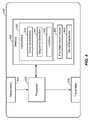
- the device 100 may be a mobile communication device (e.g., a cell phone), a smart phone, a tablet computing device, a laptop computing device, a portable digital assistant (PDA) device, or other electronic device.
- the device 100 includes a transmitter 110 (e.g., a speaker or transducer), one or more receiver(s) 120 (e.g., one or more microphones), a memory 130, and a filter 140.
- the transmitter 110 may be configured to transmit a signal 112 according to a pre-determined transmission sequence.
- the transmitter 110 may be an ultrasound transmitter configured to transmit an ultrasound signal according to the pre-determined transmission sequence.
- the memory 130 may store signal data 134.
- the signal data 134 may include information descriptive of the pre-determined transmission sequence.
- the pre-determined transmission sequence may be a pseudorandom noise (PN) sequence that may be locally unique to the device 100.
- PN pseudorandom noise
- the signal data 134 may include information descriptive of a plurality of transmission sequences (e.g., a plurality of gold codes, a plurality of kasami codes, a plurality of barker codes, etc.), and the device 100 may select the pre-determined transmission sequence from among of the plurality of transmission sequences such that the signal 112 transmitted from the transmitter 110 is locally unique to the device 100.
- the memory 130 may store pre-determined values 132 associated with the pre-determined transmission sequence.
- the filter 140 may be configured to perform echo cancellation operations on input signals received at the receiver(s) 120 using the pre-determined values 132.
- the pre-determined values 132 may include values of the signal data 134 after particular mathematical operations have been performed on them. For example, since the signal data 134 are pre-determined, computational demanding calculations related to the signal data 134 be performed in advance (e.g., before the predetermined signal is transmitted) and stored as the pre-determined values 132 to reduce computational burden during operation of the device 100.
- one or more signals may be received as an input signal at the receiver(s) 120.
- the one or more signals may include a signal 182 received from a source 180 (e.g., a transmitter of another device not shown in FIG. 1 ) and an echo signal 112).
- the device 100 may be configured to determine a position of the source 180 (or another operation) based on the signal 182.
- An input signal may be filtered to remove the echo signal 112 to facilitate accurate determination of the position of the source 180.
- the device 100 processes the input signal at the filter 140 based on the pre-determined values 132 to reduce or eliminate the signal 112 from the input signal.
- the filter 140 may include a first processing path 142 and a second processing path 144.
- the first processing path 142 includes a plurality of processing blocks, such as a first processing block 150, a second processing block 154, and a third processing block 158.
- the second processing path 144 includes a fourth processing block 162.
- the terms processing path and processing block are used to describe each of the elements 142, 144, and 150, 154, 158, 162 for simplicity of description.
- processing path and processing block are not intended to require particular physical circuitry; rather, processing paths and processing blocks are used to describe particular portions of the filter 140 that are operable to implement particular functions, such as the functions described with reference to each of the processing paths 142, 144 and the processing blocks 150, 154, 158, 162.
- processing path and processing block may, in a particular embodiment, refer to one or more circuits or portions of a circuit that perform a particular function associated with the filter 140.
- processing path and processing block may refer to instructions stored in a computer-readable storage medium that, when executed by a processor, cause the processor to initiate execution of a particular function associated with the filter 140.
- the input signal may be sampled by the one or more receiver(s) 120.
- a sample of the input signal may be provided to the filter 140 as a frame 170 (e.g., a digitized representation of the echo signal 112 and the signal 182 combined).
- the filter 140 may perform echo cancellation on the frame 170 using the pre-determined values 132 to reduce or eliminate the echo signal 112.
- H 0 ⁇ PN 0 corresponds to the signal 112 (e.g., the echo signal to be cancelled by the filter 140) and H 1 ⁇ PN 1 corresponds to the signal 182 received from the source 180.
- the impulse response 114 may indicate how acoustics of an area surrounding the device 100 (e.g., a room where device 100 is located) affect the signal 112, and the impulse response 184 may indicate how acoustics of an area surrounding the source 180 (e.g., a room where source 180 is located) affect the signal 182.
- the impulse response 114 may be different from the impulse response 184 even when the device 100 and the source 180 are located in the same area.
- the filter 140 may receive the frame 170 from the receiver(s) 120 and provide the frame 170 to the first processing path 142 and the second processing path 144.
- the first processing path 142 may provide the frame 170 to the first processing block 150.
- the first processing block 150 may be configured to perform convolution of the frame 170 with the pre-determined values 132 to produce a second frame 152.
- the frame V may indicate a correlation between the pre-determined values 132 (e.g., an approximation of the pre-determined transmission sequence of the signal 112) and the input signal (e.g., the frame X ).
- the transmission sequence, PN 0 , of the device 100 and the transmission sequence, PN 1 , of the source 180 are selected to be substantially orthogonal.
- the second frame 152, V may approximate H 0 ⁇ PN 0 ⁇ PN 0 based on the correlation between the first frame 170, X , and the pre-determined values 132.
- the second frame 152 (e.g., the frame V ) may be provided from the first processing block 150 to the second processing block 154 where the frame V is deconvoluted by PN 0 ⁇ PN 0 to produce a third frame 156.
- the second processing block 154 may perform de-convolution of the frame V to remove PN 0 ⁇ PN 0 using a set of values 146.
- the frame C may correspond to an estimate of the impulse response 114, that is C is an estimate of H 0 .
- the third frame 156 (e.g., the frame C ) may be provided to the third processing block 158.
- the frame ECHO may represent an estimate of a portion of the frame X corresponding to the echo signal 112) to be cancelled by the filter 140.
- the fourth processing block 162 may receive the fourth frame 160 from the third processing block 158 and the frame 170 (e.g., the frame X ) as inputs and generate an output frame 164.
- the fourth processing block 162 may generate the output frame 164 by subtracting the frame ECHO (e.g., the estimate of the echo signal 112) from the frame X .
- the output frame 164 may correspond to an estimate of H 1 ⁇ PN 1 (i.e., the signal 182 convoluted by the impulse response 184).
- the device 100 may consume less power due to the reduced computational complexity of the echo cancellation filter 140 as compared to other echo cancellation filters, such as an adaptive feedback filter.
- an adaptive feedback filter may dynamically adapt to a transmitted signal and a received signal in order to determine both a transmission sequence ( PN n ) and an impulse response ( H n ) corresponding to an unknown echo signal.
- the filter 140 performs echo cancellation on a received signal (e.g., the frame X ) using the pre-determined values 132 (e.g., a pre-transmission sequence ( PN 0 )) stored at the memory 130.
- the computational complexity of the filter 140 may be reduced because the transmission sequence of the device 100 is pre-determined and stored at the memory 130 as the pre-determined values 132.
- the filter 140 need only estimate the impulse response 114 ( H 0 ) using convolution as described with reference to the processing blocks 150, 154, 158.
- implementation costs may be reduced due to reduced computational resources used to perform echo cancellation using the filter 140 (i.e., by performing convolution operations on a received signal using the pre-determined values 132) as compared to other filters, such as the adaptive feedback filter where both the transmission sequence and the impulse response are unknown.
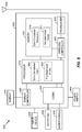
- the device 200 may be a mobile communication device (e.g., a cell phone), a smart phone, a tablet computing device, a laptop computing device, a portable digital assistant (PDA) device, or other electronic device.
- the device 200 includes a transmitter 202, one or more receiver(s) 204, a memory 206, and a filter 208.
- the transmitter 202 may be configured to transmit a signal 272 according to a pre-determined transmission sequence.
- the transmitter 202 may be an ultrasound transmitter configured to transmit an ultrasound signal according to the pre-determined transmission sequence.
- the memory 206 may store signal data 242.
- the signal data 242 may include information descriptive of the pre-determined transmission sequence.
- the pre-determined transmission sequence may be a pseudorandom noise (PN) sequence that may be locally unique to the device 200.
- PN pseudorandom noise
- the signal data 242 may include information descriptive of a plurality of transmission sequences (e.g., a plurality of gold codes, a plurality of kasami codes, a plurality of barker codes, etc.), and the device 200 may select the pre-determined transmission sequence from among of the plurality of transmission sequences such that the signal 272 transmitted from the transmitter 202 is locally unique to the device 200.
- the memory 206 may store pre-determined values 240 associated with the pre-determined transmission sequence.
- pre-determined values 240 may include pre-calculated values based on the signal data 242, such as a fast Fourier transform (FFT) of the pre-determined transmission sequence that is locally unique to the device 200.
- FFT fast Fourier transform
- the filter 208 may be configured to perform echo cancellation operations on input signals received at the receiver(s) 204 using the pre-determined values 240.
- the echo cancellation operations performed by the filter 208 may include operations in both a frequency domain (e.g., using FFT operations) and a time domain (e.g., using inverse fast Fourier transform (IFFT) operations).
- IFFT inverse fast Fourier transform
- one or more signals may be received as an input signal at the receiver(s) 204.
- the one or more signals may include a signal 282 received from a source 280 (e.g., a transmitter of another device not shown in FIG. 2 ) and an echo signal 272.
- the echo signal 272 may introduce noise into the signal 282.
- the device 200 may be configured to determine a position of the source 280 (or another operation) based on the signal 282.
- An input signal received at the one or more receiver(s) 204 may be filtered to remove the echo signal 272 to improve accuracy of the determination of the position of the source 280.
- the filter 208 may include a first processing block 250, a first processing path 210 and a second processing path 212.
- the first processing path 210 includes a plurality of processing blocks, such as a second processing block 252, a third processing block 254, a fourth processing block 256, a fifth processing block 258, and a sixth processing block 260.
- the second processing path 212 includes a seventh processing block 262. The terms processing path and processing block are used to describe each of the elements 210, 212, and 250, 252, 254, 256, 258, 260, 262 for simplicity of description.
- processing path and processing block are not intended to require particular physical circuitry; rather, processing paths and processing blocks are used to describe particular portions of the filter 208 that are operable to implement particular functions, such as the functions described with reference to each of the processing paths 210, 212 and the processing blocks 250, 252, 254, 256, 258, 260, 262.
- the terms processing path and processing block may, in a particular embodiment, refer to one or more circuits or portions of a circuit that perform a particular function associated with the filter 208.
- the terms processing path and processing block may refer to instructions stored in a computer-readable storage medium that, when executed by a processor, cause the processor to initiate execution of a particular function associated with the filter 208.
- An input signal received at the one or more receiver(s) 204 may be sampled by the one or more receiver(s) 204.
- a sample of the input signal may be provided to the filter 208 as a frame 218.
- the filter 208 may perform echo cancellation on the frame 218 using the pre-determined values 240 to reduce or eliminate the echo signal 272.
- the first processing block 250 may perform an FFT operation on the frame X to generate a frame 220.
- the FFT operation herein is just for an exemplary purpose and any other generally known time-to-frequency domain transform techniques such as, without limitation, discrete Cosine transform, discrete Fourier transform, or Wavelet transform, may be performed in the first processing block 250, instead of the FFT.
- H 0 ⁇ PN 0 corresponds to the echo signal 272 received at the one or more receivers 204 which is to be cancelled or reduced by the filter 208.
- H 1 ⁇ PN 1 corresponds to the signal 282 received from the source 280.
- the impulse response 274 may indicate how acoustics of an area surrounding the device 200 (e.g., a room where device 200 is located) affect the signal 272, and the impulse response 284 may indicate how acoustics of an area surrounding the source 280 (e.g., a room where source 280 is located) affect the signal 282.
- the impulse response 274 may be different from the impulse response 284 even when the device 200 and the source 280 are located in the same area (e.g., the same room).
- the first processing block 250 may provide the frame 220 to the first processing path 210 and to the second processing path 212.
- the first processing path 210 may provide the frame 220 to the second processing block 252.
- the second processing block 252 may be configured to multiply the frame 220 by FFT ( PN 0 ) determined from the pre-determined values 240 to generate a second processed frame 222.
- the second processing block 252 multiplies the FFT ( X ) by the FFT ( PN 0 ) , which is mathematically equivalent to convolution of the frame X with PN 0 in the time domain (e.g., as described with reference to the first processing block 150 of FIG. 1 ).
- the second frame 222, frame FFT_IN where the frame FFT_IN represents a correlation of the PN 0 with the frame X in the time domain.
- the second frame 222 may be provided to the third processing block 254.
- the third processing block 254 may perform an IFFT operation on the second frame 222 to produce a third frame 224.
- the IFFT operation herein is just for an exemplary purpose and any other generally known frequency-to-time domain transform techniques such as, without limitation, inverse discrete Cosine transform, inverse discrete Fourier transform, or inverse Wavelet transform, may be performed in the third processing block 254, instead of the IFFT.
- the third frame 224, frame V may indicate a correlation between the PN 0 and the input signal (e.g., the frame X ) in the time domain. For example, assuming that the signal 112 of FIG. 1 and the signal 272 of FIG.
- the frame V of FIG. 2 may be the same as the frame V of FIG. 1 provided the signal 182 and 282 is same or substantially similar.
- the third frame 224 (e.g., the frame V ) may be provided from the third processing block 254 to the fourth processing block 256 where the frame V is deconvoluted from PN 0 ⁇ PN 0 to produce a fourth frame 226.
- the fourth processing block 256 may perform de-convolution of the frame V from PN 0 ⁇ PN 0 using a set of values 270.
- the set of values 270 may correspond to the set of values 146 described with reference to FIG. 1 .
- the fourth frame 226 may be a frame C , where the frame C corresponds to an estimate of the impulse response 274 (e.g., an estimation of H 0 ).
- the fourth frame 226 (e.g., the frame C ) may be provided to the fifth processing block 258.
- the fifth processing block 258 may perform a FFT operation on the fourth frame 226 (e.g., FFT(C)) to generate a fifth frame 228, FFT_C , which corresponds to the estimate of the impulse response 274 in the frequency domain.
- FFT operation herein is just for an exemplary purpose and any other generally known time-to-frequency domain transform techniques such as, without limitation, discrete Cosine transform, discrete Fourier transform, or Wavelet transform, may be performed in the fifth processing block 258, instead of the FFT.
- the fifth frame 228 (e.g., the frame FFT_C ) may be provided to the sixth processing block 260.
- the sixth processing block 260 may be configured to multiply the fifth frame 228 by the pre-determined values 240 (e.g., the FFT ( PN 0 )) to produce a sixth frame 230, FFT_OUT .
- Multiplying the frame FFT_C (e.g., the FFT (C)) by the pre-determined values 240 (e.g., the FFT ( PN 0 )) in the frequency domain is mathematically equivalent to convolution of the frame C by the pre-determined values 240 in the time domain, as described with reference to the first processing block 158 of FIG. 1 .
- the sixth frame 230 (e.g., the frame FFT_OUT ) may represent, in the frequency domain, a portion of the frame X corresponding to the echo signal 272 to be cancelled by the filter 208.
- the seventh processing block 262 may receive the sixth frame 230 (e.g., the frame FFT_OUT ) from the sixth processing block 260 and the frame 220 (e.g., the frame FFT X ) as inputs and generate an output frame 232.
- the seventh processing block 262 may generate the output frame 232 by subtracting the frame FFT_OUT (e.g., the signal 272) from the frame FFT_X .
- the output frame 232 may represent an estimate of the signal 282 in the frequency domain.
- the device 200 may consume less power due to the reduced computational complexity of the echo cancellation filter 208 as compared to other echo cancellation filters, such as an adaptive feedback filter.
- an adaptive feedback filter may dynamically adapt to a transmitted signal and a received signal in order to determine both a transmission sequence ( PN n ) and an impulse response ( H n ) corresponding to an unknown echo signal.
- the filter 140 performs echo cancellation on a received signal (e.g., the frame X ) using the pre-determined values 240 (e.g., FFT ( PN 0 )) stored at the memory 206.
- the computational complexity of the filter 208 may be reduced because calculations based on the transmission sequence of the device 200 can be done in advance with results stored at the memory 206 as the pre-determined values 240.
- the filter 208 only estimates the impulse response ( H 0 ), as described with reference to the processing block 256.
- the impulse response e.g., the frame FFT_C
- the impulse response may be estimated using a combination of time domain processing (e.g., de-convolution) and frequency domain processing.
- implementation costs may be reduced due to computational resources used to perform echo cancellation using the filter 208 as compared to other filters, such as the adaptive feedback filter.
- the multi-user peer-to-peer positioning system 300 includes a first electronic device 302 and a second electronic device 340.
- the first electronic device 302 includes microphones 304, 306, 308 and a transmitter 310.
- the microphones 304, 306, 308 may correspond to the receiver(s) 120 described with reference to FIG. 1 or the receiver(s) 204 described with reference to FIG. 2 and the transmitter 310 may correspond to the transmitter 110 described with reference to FIG. 1 or the transmitter 202 described with reference to FIG. 2 .
- FIG. 3 an illustrative embodiment of a multi-user peer-to-peer positioning system 300 is shown.
- the multi-user peer-to-peer positioning system 300 includes a first electronic device 302 and a second electronic device 340.
- the first electronic device 302 includes microphones 304, 306, 308 and a transmitter 310.
- the microphones 304, 306, 308 may correspond to the receiver(s) 120 described with reference to FIG. 1 or the receiver(s) 204 described
- the first electronic device 302 may transmit a first signal 320 (e.g., a first ultrasound signal) from the transmitter 310 according to a first transmission sequence
- the second electronic device 340 may transmit a second signal 350 (e.g., a second ultrasound signal) from the transmitter 342 according to a second transmission sequence.
- the first signal 320 is designated by a first pattern 322
- the second signal 350 is designated by a second pattern 352.
- the first electronic device 302 may receive the second signal 350 at one or more of the microphones 304, 306, 308 and may determine a location of the second electronic device 340 based on the second signal 350 using triangulation. For example, in FIG. 3 , the first electronic device 302 receives the second signal 350 as a signal 350a at the microphone 304, a signal 350b at the microphone 308, and a signal 350c at the microphone 306. The first electronic device 302 may use time delays associated with each of the signals 350a, 350b, 350c to estimate, or triangulate, the position of the second electronic device 340.
- estimating the position of the second electronic device 340 may include determining an angle ⁇ that indicates a direction of the location of the second electronic device 340 and a distance 380.
- the distance 380 corresponds to a distance between the first electronic device 302 and the second electronic device 340. It is noted that although only three microphones are shown in FIG. 3 , the first electronic device 302 may include more than three microphones.
- the first signal 320 may be received as an echo signal (e.g., the signals 320a, 320b, 320c) at one or more of the microphones 304, 306, 308.
- the echo signals may interfere with, or otherwise degrade the accuracy of calculations of the position of the second electronic device 340.
- the first electronic device 302 includes a memory 330 and a filter 332.
- the memory 330 may store pre-determined values 334 associated with the first transmission sequence used by the transmitter 310 to transmit the first signal.
- the memory 330 may correspond to the memory 130 of FIG. 1 , or the memory 206 of FIG. 2 .
- the filter 332 may receive a frame including samples of the signal(s) received at each of the microphones 304, 306, 308 (e.g., the first signal 320 and the second signal 350) and may perform echo cancellation operations prior to calculating an estimate of the position of the second electronic device 340.
- the filter 332 may correspond to the filter 140 described with reference to FIG. 1 or the filter 208 described with reference to FIG. 2 .
- the device 302 may interact with the device 340 and other devices (not shown) to form a peer-to-peer positioning system.
- the device 302 may be configured to determine a location of other devices operating within the peer-to-peer positioning system based on the output of the filter 332.
- Each of the devices operating within the peer-to-peer positioning system may transmit a signal that is received at the device 302 (e.g., at the microphones 304, 306, 308) and used by the device 302 to determine an estimated location of each device that transmitted a signal that was received at the device 302.
- the device 302 may negotiate with each of the other devices to select a particular transmission sequence from a set of pre-determined transmission sequences (e.g., gold codes).
- the set of transmission sequences comprise a family of transmission sequences where each of the transmission sequences has a low cross-correlation relative to the other transmission sequences in the family.
- the device 302 After selecting the particular transmission sequence, the device 302 periodically transmits a signal (e.g., the signal 320) according to the selected particular transmission sequence.
- each of the transmission sequences may comprise a periodic sequence.
- the device 302 may periodically transmit the signal 320 based on a time interval. In an embodiment, the time interval may be determined based on a length of the selected particular transmission sequence.
- the first electronic device 302 may consume less power due to the reduced computational complexity of the filter 332 as compared to other echo cancellation filters, such as an adaptive feedback filter.
- the reduced computational complexity of the filter 332 may also enable the first electronic device 302 to perform faster location determinations.
- the device 400 includes a processor 402, a receiver(s) 404, a transmitter 406, and a memory 408.
- the device 400 may correspond to the device 100 of FIG. 1 , the device 200 of FIG. 2 , or the device 302 of FIG. 3 .
- the memory 408 may store instructions 420.
- the instructions 420 may be executable by the processor 402 to perform the one or more of the functions described with reference to the filter 140 of FIG. 1 or the filter 208 of FIG. 2 .
- the instructions 420 may include instructions executable to perform location determinations based on signals received at the receiver(s) 404, such as location instructions 426.
- the location instructions 426 may be executable by the processor 402 to determine, or triangulate, positions of other devices based on signals received from the other devices at the receiver(s) 404 as described with reference to FIG. 3 .
- the location instructions 426 may be executable by the processor 402 to determine an angle (e.g., the angle ⁇ described with reference to FIG. 3 ) that indicates a direction of the location of the other device and a distance (e.g., the distance 380 described with reference to FIG. 3 ).
- the instructions 420 may include instructions executable to dynamically select a particular transmission sequence from a set of transmission sequences 440 and to store pre-determined values 430 at the memory 408.
- the instructions 420 may include sequence selection instructions 424.
- the sequence selection instructions 424 may be executable by the processor 402 to select a particular transmission sequence from the set of transmission sequences 440.
- the set of transmission sequences 440 comprise gold code sequences. Each transmission sequence in the set of transmission sequences 440 may have a low cross-correlation relative to other transmission sequences in the in the set of transmission sequences 440.
- the sequence selection instructions 424 may include instructions that cause the processor 402 to communicate with other devices via a wireless communication link (e.g., a Bluetooth or Wi-Fi communication link), within a communication range of the device 400, to determine a locally unique transmission sequence to be used by the transmitter 406.
- the transmission sequence may be considered locally unique in that each device within the communication range of the device 400 may use a different transmission sequence while devices outside of the communication range of the device 400 may concurrently be using the same transmission sequence as the device 400.
- the sequence selection instructions 424 may cause the processor 402 to calculate or to access the pre-determined values 430.
- the pre-determined values 430 are stored at the memory 408 before the transmitter 406 begins transmitting a signal according to the transmission sequence.
- the sequence selection instructions 424 may cause the processor 402 to calculate the pre-determined values 430 for the selected transmission sequence and to store the pre-determined values 430 at the memory 408.
- the sequences selection instructions 424 may include instructions executable by the processor 402 to indicate, during operation, the particular selected transmission sequence and a corresponding set of the pre-determined values 430 to use for echo cancellation.
- the set of transmission sequences may include ten (10) different transmission sequences and the pre-determined values 430 may include values calculated based on each transmission sequence.
- a particular transmission sequence may be selected for use in transmissions via the transmitter 406.
- the processor 402 may use pre-determined values 430 corresponding to the particular transmission sequence used by the transmitter 406.
- only a single set of pre-determined values 430 may be generated and stored at the memory 408 using the sequence selection instructions 424.
- the device 500 includes a processor 502, a receiver(s) 504, a transmitter 506, and a memory 508.
- the device 500 may correspond to the device 100 of FIG. 1 or the device 200 of FIG. 2 .
- the memory 508 may store a set of transmission sequences 522 and pre-determined values 520.
- the processor 502 includes a filter 510, a sequence selector 512, and a location determination unit 514.
- the filter 510 may correspond to the filter 140 of FIG. 1 or the filter 208 of FIG. 2 .
- the filter 510 may include circuitry or other logic configured to perform one or more of the operations described with reference to the filter 140 of FIG. 1 or the filter 208 of FIG. 2 .
- the filter 510 may access the memory 508 to retrieve the pre-determined values 520 for use in echo cancellation operations.
- the sequence selector 512 may include circuitry or other logic configured to perform one or more of the functions described with reference to the sequence selection instructions 424 of FIG. 4 .
- the location determination unit 514 may include circuitry or other logic configured to perform one or more of the functions described with reference to the location instructions 426 of FIG. 4 .
- the filter 510, the sequence selector 512, and the location determination unit 514 may be part of the processor 502. In another embodiment, one or more of the filter 510, the sequence selector 512, and the location determination unit 514 may be external to the processor 502.
- one or more of the filter 510, the sequence selector 512, and the location determination unit 514 may be implemented by a field-programmable gate array (FPGA) device, an application-specific integrated circuit (ASIC), a special purpose processing unit, a digital signal processor (DSP), a controller, another hardware device, a firmware device, or a combination thereof.
- FPGA field-programmable gate array
- ASIC application-specific integrated circuit
- DSP digital signal processor
- controller another hardware device, a firmware device, or a combination thereof.
- the method 600 includes accessing signal data descriptive of a transmission sequence and pre-determined values associated with the transmission sequence.
- the signal data and the pre-determined values may be stored at a memory, such as the memory 130 of FIG. 1 or the memory 206 of FIG. 2 , before a signal corresponding to a particular transmission sequence is transmitted.
- the method 600 includes, at 604, transmitting a signal from a transmitter of an electronic device according to the transmission sequence.
- the method 600 includes generating a frame based on one or more signals received at a microphone of the electronic device.
- the one or more signals may include an echo signal associated with the transmitted signal.
- the method 600 includes processing the frame using the pre-determined values to produce an output frame in which a contribution associated with the echo signal is reduced.
- processing of the frame using the pre-determined values may be performed by the filter 140 of FIG. 1 .
- processing of the frame using the pre-determined values may be performed by the filter 208 of FIG. 2 .
- processing of the frame using the pre-determined values may be performed by the filter 332 of FIG.
- processing of the frame using the pre-determined values may be performed by the processor 402 using the echo cancellation instructions 422 of FIG. 4 .
- processing of the frame using the pre-determined values may be performed by the filter 510 of FIG. 5 .
- the method 700 includes receiving a first processed frame.
- the first processed frame may include, be included within, or correspond to the frame 220 of FIG. 2 which may be received at the filter 208 of FIG. 2 .
- the method 700 includes multiplying the first processed frame by pre-determined values to produce a second processed frame (e.g., the frame 222 of FIG. 2 ).
- the pre-determined values may be the pre-determined values 240 of FIG. 2 .
- the method 700 includes performing an inverse fast Fourier transform (IFFT) on the second processed frame to produce a third processed frame (e.g., the frame 224 of FIG. 2 ).
- the method 700 includes multiplying the third processed frame by a set of pre-determined values to produce a fourth processed frame (e.g., the frame 226 of FIG. 2 ).
- the set of pre-determined values may include, be included within, or correspond to the set of pre-determined values 270.
- the method 700 includes performing an FFT on the fourth processed frame to produce a fifth processed frame (e.g., the frame 228 of FIG. 2 ).
- the method 700 includes multiplying the fifth processed frame by the pre-determined values to produce a sixth processed frame (e.g., the frame 230 of FIG. 2 ), and, at 714, determining a difference between the first processed frame and the sixth processed frame.
- the difference between the first processed frame and the sixth processed frame produces an output frame (e.g., the frame 232 of FIG. 2 ) in which a contribution associated with an echo signal is reduced relative to an input frame (e.g., the input frame 218).
- FIG. 8 a block diagram of a particular illustrative embodiment of an electronic device 800 operable to support the various methods, systems, and computer-readable media described with respect to FIGs. 1-7 is shown.
- the electronic device 800 includes a processor 810, such as a digital signal processor (DSP), coupled to a memory 832.
- DSP digital signal processor
- the electronic device 800 may correspond to the device 100 of FIG. 1 or the first electronic device 200 of FIG. 2 , the device 302 of FIG. 3 , the device 400 of FIG. 4 , or the device 500 of FIG. 5 .
- the electronic device 800 includes a display controller 826 that is coupled to the processor 810 and to a display 828.
- a coder/decoder (CODEC) 834 may also be coupled to the processor 810.
- a speaker(s) 836 and microphone(s) 838 may be coupled to the CODEC 834.
- the microphone(s) 838 may be internal to the electronic device 800.
- the microphone(s) 838 may correspond to the receiver(s) 120 of FIG. 1 , the receiver(s) 204 of FIG. 2 , the microphones 304, 306, 308 of FIG. 3 , the receiver(s) 404 of FIG. 4 , or the receiver(s) 504 of FIG. 5 .
- the speaker(s) 836 may correspond to the transmitter 110 of FIG. 1 , the transmitter 202 of FIG. 2 , the transmitter 310 of FIG. 3 , the transmitter 406 of FIG. 4 , or the transmitter 506 of FIG. 5 .
- the electronic device 800 includes a wireless controller 840 that may be coupled to a transceiver 850 that is coupled to an antenna 842.
- the processor 810, the display controller 826, the memory 832, the CODEC 834, the transceiver 850, and the wireless controller 840 are included in a system-in-package or a system-on-chip device 822.
- an input device 830 and a power supply 844 are coupled to the system-on-chip device 822.
- the display 828, the input device 830, the speaker(s) 836, the microphone 838, the wireless antenna 842, and the power supply 844 may be external to the system-on-chip device 822.
- each of the display 828, the input device 830, the speaker(s) 836, the microphone(s) 838, the wireless antenna 842, and the power supply 844 may be coupled to a component of the system-on-chip device 822, such as an interface or a controller.
- the electronic device 800 may store pre-determined values, such as the pre-determined values 882, at the memory 832.
- the pre-determined values may be stored at a memory (i.e., a cache memory) of the processor 810 as the pre-determined values 872.
- the processor 810 may include sequence selection logic (e.g., the sequence selector 512 of FIG. 5 ) configured to access the pre-determined values at the memory 832 or the pre-determined values 882.
- the electronic device 800 may receive signals (e.g., ultrasound signals) at the microphone(s) 838. The received signals may include an echo signal generated by the speaker(s) 836.
- the CODEC 834 may process the received signals to generate an input frame (e.g., the input frame 170 of FIG. 1 or the input frame 218 of FIG. 2 ) and provide the input frame to the processor 810.
- the input frame may be generated by the processor 810.
- the processor 810 may include echo cancellation logic 880 configured to process the input frame to produce an output frame (e.g., the output frame 164 of FIG. 1 or the output frame 232 of FIG. 2 ). A contribution of the echo signal to the output frame may be less than a contribution of the echo signal to the input frame.
- the echo cancellation logic 880 may correspond to the filter 140 of FIG. 1 and may be configured to perform one or more of the operations described with reference to the processing blocks 150, 154, 158, 162 of FIG. 1 .
- the echo cancellation logic 880 may correspond to the filter 208 of FIG. 2 and may be configured to perform one or more of the operations described with reference to the processing blocks 250-262 of FIG. 2 .
- the echo cancellation logic 880 may correspond to the filter 332 of FIG. 3 .
- the echo cancellation logic 880 may correspond to the filter 510 described with reference to FIG. 5 .
- the memory 832 may store echo cancellation instructions 870 that cause the processor 810 to perform echo cancellation operations on the input frame to produce the output frame as described with reference to FIGs. 1-7 .
- a contribution of the echo signal to the output frame may be less than a contribution of the echo signal to the input frame.
- the echo cancellation instructions 870 may correspond to the echo cancellation instructions 422 of FIG. 4 .
- the echo cancellation instructions 870 may be executable by the processor 810 to perform one or more of the operations described with reference to the processing blocks 150, 154, 158, 162 of FIG. 1 or the operations described with reference to the processing blocks 250-262 of FIG. 2 .
- the processor 810 may be configured to generate the pre-determined values (e.g., values that are determined before a transmission sequence related to the pre-determined values is sent, such as the pre-determined values 882 or the pre-determined values 872) based on signal data descriptive of a pre-determined transmission sequence.
- the processor 810 may include a sequence selector (e.g., the sequence selector 512 of FIG. 5 ) configured to generate the pre-determined values and to store the pre-determined values at the memory (e.g., the memory 832 or a cache memory of the processor 810) or to access the pre-determined values at the memory 832.
- the memory 832 may store sequence selection instructions (e.g., the sequence selection instructions 424 of FIG. 4 ) that cause the processor 810 to generate the pre-determined values and to store the pre-determined values at the memory (e.g., the memory 832 or a cache memory of the processor 810).
- the processor 810 may be configured to determine a location of another electronic device (not shown) based on the output frame as described with reference to FIG. 3 . For example, a particular portion of the received signals may correspond to a signal generated at the other electronic device.
- the processor 810 may use triangulation to determine a location (i.e., a direction and distance) of the other electronic device relative to the electronic device 800 based on the output frame.
- the processor 810 may include location logic (e.g., the location determination unit 514 of FIG. 5 ) for use in determining the location of the other electronic device.
- the memory 832 may store location instructions (e.g., the location instructions 426 of FIG. 4 ) that cause the processor 810 to determine the location of the other electronic device.
- a system may include means for transmitting a signal according to a transmission sequence.
- the means for transmitting the signal may include the speaker(s) 836, the transmitter 110 of FIG. 1 , the transmitter 202 of FIG. 2 , the transmitter 310 of FIG. 3 , the transmitter 406 of FIG. 4 , or the transmitter 506 of FIG. 5 .
- the system may include means for receiving one or more signals.
- the means for receiving one or more signals may include the microphone(s) 838, the receiver(s) 120 of FIG. 1 , the receiver(s) 204 of FIG. 2 , the microphones 304-308 of FIG. 3 , the receiver(s) 404 of FIG.
- the system may include means for storing pre-determined values associated with a transmission sequence.
- the means for storing the pre-determined values associated with the transmission sequence may include the memory 832, the memory 130 of FIG. 1 , the memory 206 of FIG. 2 , the memory 330 of FIG. 3 , the memory 408 of FIG. 4 , or the memory 508 of FIG. 5 .
- the means for storing the pre-determined values associated with the transmission sequence may include a memory (e.g., a cache memory) or register of the processor 810.
- the system may include means for generating an input (e.g., the input frame 170 of FIG. 1 or the input frame 218 of FIG. 2 ) based on the one or more received signals.
- the means for generating the input based on the one or more received signals may include the processor 810.
- the means for generating the input based on the one or more received signals may include the receiver(s) 120 of FIG. 1 or the receiver(s) 204 of FIG. 2 .
- the means for generating the input based on the one or more received signals may include the filter 510 of FIG. 5 .
- the means for generating an input based on the one or more received signals may be implemented by a field-programmable gate array (FPGA) device, an application-specific integrated circuit (ASIC), a processing unit such as a central processing unit (CPU), a digital signal processor (DSP), a controller, another hardware device, a firmware device, or any combination thereof configured to generate an input based on one or more received signals.
- FPGA field-programmable gate array
- ASIC application-specific integrated circuit
- CPU central processing unit
- DSP digital signal processor
- controller another hardware device, a firmware device, or any combination thereof configured to generate an input based on one or more received signals.
- the system may include means for processing the input based on the pre-determined values to produce a first output (e.g., the frame 160 of FIG. 1 or the frame 230 of FIG. 2 ).
- the first output may be indicative of a contribution of the transmitted signal to the input.
- the means for processing the input based on the pre-determined values may include the echo cancellation logic 880, which may be incorporated within the processor 810.
- the echo cancellation logic 880 may be external to the processor 810 and may be implemented by a FPGA device, an ASIC, a processing unit such as a CPU, a DSP, a controller, another hardware device, firmware device, or any combination thereof.
- the means for processing the input based on the pre-determined values may include the first processing path 142 of FIG. 1 (e.g., the processing blocks 150, 154, 158, 162 of FIG. 1 ) of the filter 140 of FIG. 1 .
- the means for processing the input based on the pre-determined values may include the first processing path 210 of FIG. 2 (e.g., the processing blocks 250-262 of FIG. 2 ) of the filter 208 of FIG. 2 .
- the means for processing the input based on the pre-determined values may include the filter 332 of FIG. 3 .
- the first processing path 142, the first processing path 210 may be implemented by a FPGA device, an ASIC, a processing unit such as a CPU, a DSP, a controller, another hardware device, a firmware device, or any combination thereof configured to perform the functions described with reference to the processing blocks 150, 154, 158 of FIG. 1 or the processing blocks 252-260 of FIG. 2 .
- the system may include means for generating a second output (e.g., the output frame 164 of FIG. 1 or the output frame 232 of FIG. 2 ) based on a difference between the input and the first output.
- the means for generating the second output may include the echo cancellation logic 880.
- the echo cancellation logic 880 may be incorporated within the processor 810.
- the echo cancellation logic 880 may be external to the processor 810 (e.g., as application specific circuitry).
- the means for generating the second output may include the second processing path 144 (e.g., the processing block 162 of FIG. 1 ) of the filter 140 of FIG. 1 , the second processing path 212 (e.g., the processing block 262 of FIG.
- the second processing path 144 of the filter 140 of FIG. 1 or the second processing path 212 of the filter 208 of FIG. 2 may be implemented by a FPGA device, an ASIC, a processing unit such as a CPU, a DSP, a controller, another hardware device, firmware device, or any combination thereof configured to perform the functions described with reference to the processing block 162 of FIG. 1 or the processing block 262 of FIG. 2 .
- the means for generating the input may include means for receiving a frame (e.g., the frame 218 of FIG. 2 ) generated based on the one or more received signals and means for performing a fast Fourier transform (FFT) on the frame.
- the input may include a result of the FFT.
- the means for performing the FFT on the frame may include the first processing block 250 of FIG. 2 .
- the first processing block 250 may be implemented by a FPGA device, an ASIC, a processing unit such as a CPU, a DSP, a controller, another hardware device, a firmware device, or any combination thereof configured to receive a frame and perform a FFT on the frame.
- the means for processing the input includes means for determining a first product (e.g., the frame 222 of FIG. 2 ) by multiplying the input by the pre-determined values, means for performing an inverse fast Fourier transform (IFFT) on the first product, means for determining a second product (e.g., the frame 226) by multiplying a result of the IFFT (e.g., the frame 224 of FIG. 2 ) by a set of pre-determined values (e.g., the set of pre-determined values 270 of FIG.
- IFFT inverse fast Fourier transform
- the means for determining the first product, the means for performing the IFFT on the first product, the means for determining the second product, the means for performing the second FFT on the second product, and the means for multiplying a result of the second FFT may each be implemented by a FPGA device, an ASIC, a processing unit such as a CPU, a DSP, a controller, another hardware device, firmware device, or any combination thereof configured to perform the functions described with reference to the second processing block 154 of FIG. 1 .
- the means for performing the IFFT on the first product corresponds to the third processing block 254.
- the set of pre-determined values corresponds to the set of pre-determined values 132 described with reference to FIG. 1 .
- a software module may reside in random access memory (RAM), flash memory, read-only memory (ROM), programmable read-only memory (PROM), erasable programmable read-only memory (EPROM), electrically erasable programmable read-only memory (EEPROM), registers, hard disk, a removable disk, a compact disc read-only memory (CD-ROM), or any other form of non-transitory storage medium known in the art.
- An exemplary storage medium is coupled to the processor such that the processor can read information from, and write information to, the storage medium.
- the storage medium may be integral to the processor.
- the processor and the storage medium may reside in an application-specific integrated circuit (ASIC).
- ASIC application-specific integrated circuit
- the ASIC may reside in a computing device or a user terminal (e.g., a mobile phone or a PDA).
- the processor and the storage medium may reside as discrete components in a computing device or user terminal.
Landscapes
- Engineering & Computer Science (AREA)
- Physics & Mathematics (AREA)
- General Physics & Mathematics (AREA)
- Radar, Positioning & Navigation (AREA)
- Remote Sensing (AREA)
- Signal Processing (AREA)
- Cable Transmission Systems, Equalization Of Radio And Reduction Of Echo (AREA)
- Telephone Function (AREA)
- Circuit For Audible Band Transducer (AREA)
- Transducers For Ultrasonic Waves (AREA)
Claims (15)
- Verfahren, das Folgendes beinhaltet:Durchführen eines Speicherzugriffs (602) zum Abrufen von Signaldaten und Werten, wobei die Signaldaten einer Sendefolge entsprechen und wobei die Werte auf der Basis der Signaldaten berechnet werden, bevor auf den Speicher zugegriffen wird, um die Signaldaten abzurufen;Senden (604) eines ersten Signals von einem Lautsprecher eines elektronischen Geräts gemäß der Sendefolge, wobei die Signaldaten und die Werte vor dem Senden des ersten Signals in einem Speicher gespeichert werden;Erzeugen (606) eines ersten Frame auf der Basis von einem oder mehreren an einem Mikrofon des elektronischen Geräts empfangenen zweiten Signalen, wobei die ein oder mehreren zweiten Signale ein mit dem ersten Signal assoziiertes Echosignal enthalten; undVerarbeiten (608) des ersten Frame mit den Werten zum Erzeugen eines zweiten Frame, in dem ein mit dem Echosignal assoziierter Beitrag reduziert ist.
- Verfahren nach Anspruch 1, wobei das erste Signal auf der Basis der Signaldaten gesendet wird und wobei die Werte einer schnellen Fourier-Transformation FFT der Sendefolge entsprechen.
- Verfahren nach Anspruch 2, wobei das Verarbeiten (608) des ersten Frame ferner Folgendes beinhaltet:Durchführen einer FFT an dem ersten Frame zum Erzeugen eines ersten verarbeiteten Frame; undAnlegen des ersten verarbeiteten Frame an Echounterdrückungslogik, wobei die Echounterdrückungslogik zum Verarbeiten (700) des ersten verarbeiteten Frame auf der Basis der Werte konfiguriert ist.
- Verfahren nach Anspruch 3, wobei das Verarbeiten (700) des ersten verarbeiteten Frame auf der Basis der Werte Folgendes beinhaltet:Multiplizieren (704) des ersten verarbeiteten Frame mit den Werten zum Erzeugen eines zweiten verarbeiteten Frame;Durchführen (706) einer inversen schnellen Fourier-Transformation IFFT an dem zweiten verarbeiteten Frame zum Erzeugen eines dritten verarbeiteten Frame;Multiplizieren (708) des dritten verarbeiteten Frame mit einem Satz von Werten zum Erzeugen eines vierten verarbeiteten Frame;Durchführen (710) einer FFT an dem vierten verarbeiteten Frame zum Erzeugen eines fünften verarbeiteten Frame;Multiplizieren (712) des fünften verarbeiteten Frame mit den Werten zum Erzeugen eines sechsten verarbeiteten Frame; undBestimmen (714) einer Differenz zwischen dem ersten verarbeiteten Frame und dem sechsten verarbeiteten Frame.
- Verfahren nach Anspruch 4, wobei der zweite Frame auf der Basis der Differenz zwischen dem ersten verarbeiteten Frame und dem sechsten verarbeiteten Frame erzeugt wird.
- Verfahren nach Anspruch 1, wobei die Sendefolge für das elektronische Gerät logisch eindeutig ist.
- Verfahren nach Anspruch 6, wobei das elektronische Gerät ein mobiles Kommunikationsgerät ist.
- Verfahren nach Anspruch 1, wobei die ein oder mehreren zweiten Signale ein von einem zweiten elektronischen Gerät gesendetes drittes Signal beinhalten, wobei das Verfahren ferner das Bestimmen einer Position des zweiten elektronischen Geräts auf der Basis des zweiten Frame beinhaltet, wobei das zweite elektronische Gerät das dritte Signal gemäß einer zweiten Sendefolge sendet, die sich von der Sendefolge unterscheidet.
- Verfahren nach Anspruch 8, wobei die ein oder mehreren Signale Ultraschallsignale umfassen.
- Verfahren nach Anspruch 1, wobei das erste Signal ein Ultraschallsignal umfasst und wobei die Sendefolge eine periodische Folge ist.
- Computerlesbares Speichermedium, das Befehle umfasst, die bei Ausführung durch einen Prozessor bewirken, dass der Prozessor das Verfahren nach einem der vorherigen Ansprüche durchführt.
- Vorrichtung (800), die Folgendes umfasst:Mittel (110, 202, 310, 406, 506, 836) zum Senden eines ersten Signals gemäß einer Sendefolge;Mittel (120, 204, 304-308, 404, 504, 838) zum Empfangen von einem oder mehreren zweiten Signalen;Mittel (130, 206, 330, 408, 508, 832) zum Speichern von Signaldaten und Werten, wobei die Signaldaten der Sendefolge entsprechen und vor dem Senden des ersten Signals auf sie zugegriffen wird, wobei die Werte auf der Basis der Signaldaten berechnet werden, bevor auf den Speicher zugegriffen wird, um die Signaldaten abzurufen;Mittel (120, 204, 510, 810) zum Erzeugen eines Eingangs auf der Basis der ein oder mehreren zweiten Signale;Mittel (140, 142, 208, 210, 332, 402, 502, 810, 880) zum Verarbeiten des Eingangs auf der Basis der Werte zum Erzeugen eines ersten Ausgangs, wobei der erste Ausgang einen Beitrag des ersten Signals zum Eingang anzeigt; undMittel (140, 142, 208, 210, 332, 402, 502, 810, 880) zum Erzeugen eines zweiten Ausgangs auf der Basis einer Differenz zwischen dem Eingang und dem ersten Ausgang.
- Vorrichtung nach Anspruch 12, wobei das erste Signal auf der Basis der Signaldaten übertragen wird und wobei das Mittel zum Erzeugen des Eingangs Folgendes umfasst:Mittel zum Empfangen eines Frame, der auf der Basis der ein oder mehreren zweiten Signale erzeugt wurde; undMittel zum Durchführen einer schnellen Fourier-Transformation FFT an dem Frame, wobei der Eingang ein Ergebnis der FFT ist.
- Vorrichtung nach Anspruch 12, wobei die Werte einer schnellen Fourier-Transformation FFT der Sendefolge entsprechen.
- Vorrichtung nach Anspruch 14, wobei das Mittel zum Verarbeiten des Eingangs Folgendes umfasst:Mittel zum Bestimmen eines ersten Produkts durch Multiplizieren des Eingangs mit den Werten;Mittel zum Durchführen einer inversen schnellen Fourier-Transformation IFFT an dem ersten Produkt;Mittel zum Bestimmen eines zweiten Produkts durch Multiplizieren eines Ergebnisses der IFFT mit einem Satz von Werten;Mittel zum Durchführen einer zweiten FFT an dem zweiten Produkt; undMittel zum Multiplizieren eines Ergebnisses der zweiten FFT mit den Werten zum Erzeugen eines ersten Ausgangs,wobei der Satz von Werten optional einer Toeplitz-Matrix entspricht.
Applications Claiming Priority (3)
| Application Number | Priority Date | Filing Date | Title |
|---|---|---|---|
| US201261727011P | 2012-11-15 | 2012-11-15 | |
| US13/841,359 US9210270B2 (en) | 2012-11-15 | 2013-03-15 | Echo cancellation for ultrasound |
| PCT/US2013/065948 WO2014078016A1 (en) | 2012-11-15 | 2013-10-21 | Echo cancellation using ultrasound |
Publications (2)
| Publication Number | Publication Date |
|---|---|
| EP2920947A1 EP2920947A1 (de) | 2015-09-23 |
| EP2920947B1 true EP2920947B1 (de) | 2016-09-21 |
Family
ID=50682228
Family Applications (1)
| Application Number | Title | Priority Date | Filing Date |
|---|---|---|---|
| EP13785769.4A Active EP2920947B1 (de) | 2012-11-15 | 2013-10-21 | Echounterdrückung mittels ultraschall |
Country Status (6)
| Country | Link |
|---|---|
| US (1) | US9210270B2 (de) |
| EP (1) | EP2920947B1 (de) |
| JP (1) | JP5978404B2 (de) |
| KR (1) | KR101651794B1 (de) |
| CN (1) | CN104769926B (de) |
| WO (1) | WO2014078016A1 (de) |
Families Citing this family (26)
| Publication number | Priority date | Publication date | Assignee | Title |
|---|---|---|---|---|
| US9831843B1 (en) | 2013-09-05 | 2017-11-28 | Cirrus Logic, Inc. | Opportunistic playback state changes for audio devices |
| US9525940B1 (en) | 2014-03-05 | 2016-12-20 | Cirrus Logic, Inc. | Multi-path analog front end and analog-to-digital converter for a signal processing system |
| US9774342B1 (en) * | 2014-03-05 | 2017-09-26 | Cirrus Logic, Inc. | Multi-path analog front end and analog-to-digital converter for a signal processing system |
| US9306588B2 (en) | 2014-04-14 | 2016-04-05 | Cirrus Logic, Inc. | Switchable secondary playback path |
| KR102208696B1 (ko) * | 2014-05-13 | 2021-01-28 | 삼성전자주식회사 | 센서 데이터 획득 방법 및 그 장치 |
| US10785568B2 (en) | 2014-06-26 | 2020-09-22 | Cirrus Logic, Inc. | Reducing audio artifacts in a system for enhancing dynamic range of audio signal path |
| US9596537B2 (en) | 2014-09-11 | 2017-03-14 | Cirrus Logic, Inc. | Systems and methods for reduction of audio artifacts in an audio system with dynamic range enhancement |
| US9503027B2 (en) | 2014-10-27 | 2016-11-22 | Cirrus Logic, Inc. | Systems and methods for dynamic range enhancement using an open-loop modulator in parallel with a closed-loop modulator |
| US9584911B2 (en) | 2015-03-27 | 2017-02-28 | Cirrus Logic, Inc. | Multichip dynamic range enhancement (DRE) audio processing methods and apparatuses |
| US9959856B2 (en) | 2015-06-15 | 2018-05-01 | Cirrus Logic, Inc. | Systems and methods for reducing artifacts and improving performance of a multi-path analog-to-digital converter |
| US9955254B2 (en) | 2015-11-25 | 2018-04-24 | Cirrus Logic, Inc. | Systems and methods for preventing distortion due to supply-based modulation index changes in an audio playback system |
| US9543975B1 (en) | 2015-12-29 | 2017-01-10 | Cirrus Logic, Inc. | Multi-path analog front end and analog-to-digital converter for a signal processing system with low-pass filter between paths |
| US9880802B2 (en) | 2016-01-21 | 2018-01-30 | Cirrus Logic, Inc. | Systems and methods for reducing audio artifacts from switching between paths of a multi-path signal processing system |
| US9998826B2 (en) | 2016-06-28 | 2018-06-12 | Cirrus Logic, Inc. | Optimization of performance and power in audio system |
| US10545561B2 (en) | 2016-08-10 | 2020-01-28 | Cirrus Logic, Inc. | Multi-path digitation based on input signal fidelity and output requirements |
| US10263630B2 (en) | 2016-08-11 | 2019-04-16 | Cirrus Logic, Inc. | Multi-path analog front end with adaptive path |
| US9813814B1 (en) | 2016-08-23 | 2017-11-07 | Cirrus Logic, Inc. | Enhancing dynamic range based on spectral content of signal |
| US9762255B1 (en) | 2016-09-19 | 2017-09-12 | Cirrus Logic, Inc. | Reconfiguring paths in a multiple path analog-to-digital converter |
| US9780800B1 (en) | 2016-09-19 | 2017-10-03 | Cirrus Logic, Inc. | Matching paths in a multiple path analog-to-digital converter |
| US9929703B1 (en) | 2016-09-27 | 2018-03-27 | Cirrus Logic, Inc. | Amplifier with configurable final output stage |
| US9967665B2 (en) | 2016-10-05 | 2018-05-08 | Cirrus Logic, Inc. | Adaptation of dynamic range enhancement based on noise floor of signal |
| US10321230B2 (en) | 2017-04-07 | 2019-06-11 | Cirrus Logic, Inc. | Switching in an audio system with multiple playback paths |
| US10008992B1 (en) | 2017-04-14 | 2018-06-26 | Cirrus Logic, Inc. | Switching in amplifier with configurable final output stage |
| US9917557B1 (en) | 2017-04-17 | 2018-03-13 | Cirrus Logic, Inc. | Calibration for amplifier with configurable final output stage |
| US10277981B1 (en) * | 2018-10-02 | 2019-04-30 | Sonos, Inc. | Systems and methods of user localization |
| TWI790718B (zh) * | 2021-08-19 | 2023-01-21 | 宏碁股份有限公司 | 會議終端及用於會議的回音消除方法 |
Family Cites Families (17)
| Publication number | Priority date | Publication date | Assignee | Title |
|---|---|---|---|---|
| CA2107198A1 (en) | 1993-09-28 | 1995-03-29 | D. Erle Nelson | Method and apparatus for accurate acoustic distance measurement |
| US6563925B1 (en) * | 1999-04-07 | 2003-05-13 | Ericsson Inc. | Method and apparatus for space-time echo cancellation |
| JP2000341658A (ja) * | 1999-05-27 | 2000-12-08 | Nec Eng Ltd | 話者方向検出システム |
| US7515704B2 (en) | 2004-01-05 | 2009-04-07 | Telukuntla Krishna Prabhu N V R | Method, apparatus and articles incorporating a step size control technique for echo signal cancellation |
| US7720232B2 (en) | 2004-10-15 | 2010-05-18 | Lifesize Communications, Inc. | Speakerphone |
| US20080317241A1 (en) | 2006-06-14 | 2008-12-25 | Derek Wang | Code-based echo cancellation |
| US8396206B2 (en) * | 2007-02-15 | 2013-03-12 | Infineon Technologies Ag | Multi-channel communication device and methods for reducing echoes by inserting a training sequence under a spectral mask |
| DE112007003625T5 (de) | 2007-08-24 | 2010-07-15 | Fujitsu Ltd., Kawasaki | Echounterdrückungsvorrichtung, echounterdrückungssystem, Echounterdrückungsverfahren und Computerprogramm |
| EP2045620B1 (de) | 2007-09-26 | 2015-08-12 | Harman Becker Automotive Systems GmbH | Messung der akustischen Laufzeit |
| JP5405130B2 (ja) * | 2009-01-09 | 2014-02-05 | クラリオン株式会社 | 音再生装置および音再生方法 |
| EP2221983B1 (de) | 2009-02-20 | 2011-08-31 | Harman Becker Automotive Systems GmbH | Akustische Echokompensierung |
| FR2952263B1 (fr) | 2009-10-29 | 2012-01-06 | Univ Paris Descartes | Procede et dispositif d'annulation d'echo acoustique par tatouage audio |
| JP2011227199A (ja) * | 2010-04-16 | 2011-11-10 | Nec Casio Mobile Communications Ltd | 雑音抑圧装置、雑音抑圧方法及びプログラム |
| US8619970B2 (en) | 2010-06-16 | 2013-12-31 | Lectrosonics, Inc. | Echo cancellers and echo cancelling methods |
| US8553904B2 (en) * | 2010-10-14 | 2013-10-08 | Hewlett-Packard Development Company, L.P. | Systems and methods for performing sound source localization |
| GB2495131A (en) * | 2011-09-30 | 2013-04-03 | Skype | A mobile device includes a received-signal beamformer that adapts to motion of the mobile device |
| US8903108B2 (en) * | 2011-12-06 | 2014-12-02 | Apple Inc. | Near-field null and beamforming |
-
2013
- 2013-03-15 US US13/841,359 patent/US9210270B2/en not_active Expired - Fee Related
- 2013-10-21 CN CN201380057220.1A patent/CN104769926B/zh active Active
- 2013-10-21 WO PCT/US2013/065948 patent/WO2014078016A1/en active Application Filing
- 2013-10-21 JP JP2015543055A patent/JP5978404B2/ja not_active Expired - Fee Related
- 2013-10-21 KR KR1020157011615A patent/KR101651794B1/ko active IP Right Grant
- 2013-10-21 EP EP13785769.4A patent/EP2920947B1/de active Active
Also Published As
| Publication number | Publication date |
|---|---|
| JP2016500236A (ja) | 2016-01-07 |
| JP5978404B2 (ja) | 2016-08-24 |
| EP2920947A1 (de) | 2015-09-23 |
| US9210270B2 (en) | 2015-12-08 |
| WO2014078016A1 (en) | 2014-05-22 |
| CN104769926A (zh) | 2015-07-08 |
| US20140135077A1 (en) | 2014-05-15 |
| CN104769926B (zh) | 2017-03-22 |
| KR101651794B1 (ko) | 2016-08-26 |
| KR20150084814A (ko) | 2015-07-22 |
Similar Documents
| Publication | Publication Date | Title |
|---|---|---|
| EP2920947B1 (de) | Echounterdrückung mittels ultraschall | |
| US20190199850A1 (en) | Detecting the location of a phone using rf wireless and ultrasonic signals | |
| CN105472189B (zh) | 回波消除检测器、消除回波的方法和比较发生器 | |
| US9185199B2 (en) | Method and apparatus for acoustically characterizing an environment in which an electronic device resides | |
| US20160266235A1 (en) | Driver side location detection | |
| CN101010722B (zh) | 用于检测语音信号中话音活动的设备和方法 | |
| KR101470528B1 (ko) | 적응 빔포밍을 위한 사용자 방향의 소리 검출 기반의 적응모드 제어 장치 및 방법 | |
| EP2277323B1 (de) | Sprachverstärkung unter benutzung einer mehrzahl von mikrofonen an einer mehrzahl von geräten | |
| US9449594B2 (en) | Adaptive phase difference based noise reduction for automatic speech recognition (ASR) | |
| CN101719969A (zh) | 判断双端对话的方法、系统以及消除回声的方法和系统 | |
| JP2016500236A5 (de) | ||
| WO2015184893A1 (zh) | 移动终端通话语音降噪方法及装置 | |
| CN102855880A (zh) | 用于多话筒音频设备的去噪方法 | |
| EP2806424A1 (de) | Verbesserte Rauschunterdrückung | |
| WO2018221206A1 (ja) | エコー抑圧装置、エコー抑圧方法及びエコー抑圧プログラム | |
| KR20150130845A (ko) | 전자장치의 위치 측정 장치 및 방법 | |
| KR100949910B1 (ko) | 스펙트럼 차감을 이용한 음향학적 반향 제거 방법 및 장치 | |
| US20160309278A1 (en) | Determining doppler shift in an audio chirp signal | |
| KR102012522B1 (ko) | 방향성 음향 신호 처리 장치 | |
| Nakayama et al. | Acoustic distance measurement based on phase interference using the cross-spectral method with adjacent microphones | |
| US11533559B2 (en) | Beamformer enhanced direction of arrival estimation in a reverberant environment with directional noise | |
| JP2021168455A (ja) | エコー抑圧装置、エコー抑圧方法及びエコー抑圧プログラム | |
| JP2016025471A (ja) | エコー抑圧装置、エコー抑圧プログラム、エコー抑圧方法及び通信端末 |
Legal Events
| Date | Code | Title | Description |
|---|---|---|---|
| PUAI | Public reference made under article 153(3) epc to a published international application that has entered the european phase |
Free format text: ORIGINAL CODE: 0009012 |
|
| 17P | Request for examination filed |
Effective date: 20150422 |
|
| AK | Designated contracting states |
Kind code of ref document: A1 Designated state(s): AL AT BE BG CH CY CZ DE DK EE ES FI FR GB GR HR HU IE IS IT LI LT LU LV MC MK MT NL NO PL PT RO RS SE SI SK SM TR |
|
| AX | Request for extension of the european patent |
Extension state: BA ME |
|
| DAX | Request for extension of the european patent (deleted) | ||
| GRAP | Despatch of communication of intention to grant a patent |
Free format text: ORIGINAL CODE: EPIDOSNIGR1 |
|
| INTG | Intention to grant announced |
Effective date: 20160412 |
|
| GRAS | Grant fee paid |
Free format text: ORIGINAL CODE: EPIDOSNIGR3 |
|
| GRAA | (expected) grant |
Free format text: ORIGINAL CODE: 0009210 |
|
| AK | Designated contracting states |
Kind code of ref document: B1 Designated state(s): AL AT BE BG CH CY CZ DE DK EE ES FI FR GB GR HR HU IE IS IT LI LT LU LV MC MK MT NL NO PL PT RO RS SE SI SK SM TR |
|
| REG | Reference to a national code |
Ref country code: GB Ref legal event code: FG4D |
|
| REG | Reference to a national code |
Ref country code: CH Ref legal event code: EP |
|
| REG | Reference to a national code |
Ref country code: AT Ref legal event code: REF Ref document number: 831853 Country of ref document: AT Kind code of ref document: T Effective date: 20161015 |
|
| REG | Reference to a national code |
Ref country code: IE Ref legal event code: FG4D |
|
| REG | Reference to a national code |
Ref country code: FR Ref legal event code: PLFP Year of fee payment: 4 |
|
| REG | Reference to a national code |
Ref country code: DE Ref legal event code: R096 Ref document number: 602013011943 Country of ref document: DE |
|
| REG | Reference to a national code |
Ref country code: LT Ref legal event code: MG4D Ref country code: NL Ref legal event code: MP Effective date: 20160921 |
|
| PG25 | Lapsed in a contracting state [announced via postgrant information from national office to epo] |
Ref country code: RS Free format text: LAPSE BECAUSE OF FAILURE TO SUBMIT A TRANSLATION OF THE DESCRIPTION OR TO PAY THE FEE WITHIN THE PRESCRIBED TIME-LIMIT Effective date: 20160921 Ref country code: FI Free format text: LAPSE BECAUSE OF FAILURE TO SUBMIT A TRANSLATION OF THE DESCRIPTION OR TO PAY THE FEE WITHIN THE PRESCRIBED TIME-LIMIT Effective date: 20160921 Ref country code: LT Free format text: LAPSE BECAUSE OF FAILURE TO SUBMIT A TRANSLATION OF THE DESCRIPTION OR TO PAY THE FEE WITHIN THE PRESCRIBED TIME-LIMIT Effective date: 20160921 Ref country code: NO Free format text: LAPSE BECAUSE OF FAILURE TO SUBMIT A TRANSLATION OF THE DESCRIPTION OR TO PAY THE FEE WITHIN THE PRESCRIBED TIME-LIMIT Effective date: 20161221 |
|
| REG | Reference to a national code |
Ref country code: AT Ref legal event code: MK05 Ref document number: 831853 Country of ref document: AT Kind code of ref document: T Effective date: 20160921 |
|
| PG25 | Lapsed in a contracting state [announced via postgrant information from national office to epo] |
Ref country code: SE Free format text: LAPSE BECAUSE OF FAILURE TO SUBMIT A TRANSLATION OF THE DESCRIPTION OR TO PAY THE FEE WITHIN THE PRESCRIBED TIME-LIMIT Effective date: 20160921 Ref country code: NL Free format text: LAPSE BECAUSE OF FAILURE TO SUBMIT A TRANSLATION OF THE DESCRIPTION OR TO PAY THE FEE WITHIN THE PRESCRIBED TIME-LIMIT Effective date: 20160921 Ref country code: BE Free format text: LAPSE BECAUSE OF NON-PAYMENT OF DUE FEES Effective date: 20161031 Ref country code: LV Free format text: LAPSE BECAUSE OF FAILURE TO SUBMIT A TRANSLATION OF THE DESCRIPTION OR TO PAY THE FEE WITHIN THE PRESCRIBED TIME-LIMIT Effective date: 20160921 Ref country code: GR Free format text: LAPSE BECAUSE OF FAILURE TO SUBMIT A TRANSLATION OF THE DESCRIPTION OR TO PAY THE FEE WITHIN THE PRESCRIBED TIME-LIMIT Effective date: 20161222 |
|
| PG25 | Lapsed in a contracting state [announced via postgrant information from national office to epo] |
Ref country code: EE Free format text: LAPSE BECAUSE OF FAILURE TO SUBMIT A TRANSLATION OF THE DESCRIPTION OR TO PAY THE FEE WITHIN THE PRESCRIBED TIME-LIMIT Effective date: 20160921 Ref country code: RO Free format text: LAPSE BECAUSE OF FAILURE TO SUBMIT A TRANSLATION OF THE DESCRIPTION OR TO PAY THE FEE WITHIN THE PRESCRIBED TIME-LIMIT Effective date: 20160921 |
|
| PG25 | Lapsed in a contracting state [announced via postgrant information from national office to epo] |
Ref country code: PL Free format text: LAPSE BECAUSE OF FAILURE TO SUBMIT A TRANSLATION OF THE DESCRIPTION OR TO PAY THE FEE WITHIN THE PRESCRIBED TIME-LIMIT Effective date: 20160921 Ref country code: PT Free format text: LAPSE BECAUSE OF FAILURE TO SUBMIT A TRANSLATION OF THE DESCRIPTION OR TO PAY THE FEE WITHIN THE PRESCRIBED TIME-LIMIT Effective date: 20170123 Ref country code: AT Free format text: LAPSE BECAUSE OF FAILURE TO SUBMIT A TRANSLATION OF THE DESCRIPTION OR TO PAY THE FEE WITHIN THE PRESCRIBED TIME-LIMIT Effective date: 20160921 Ref country code: SK Free format text: LAPSE BECAUSE OF FAILURE TO SUBMIT A TRANSLATION OF THE DESCRIPTION OR TO PAY THE FEE WITHIN THE PRESCRIBED TIME-LIMIT Effective date: 20160921 Ref country code: IS Free format text: LAPSE BECAUSE OF FAILURE TO SUBMIT A TRANSLATION OF THE DESCRIPTION OR TO PAY THE FEE WITHIN THE PRESCRIBED TIME-LIMIT Effective date: 20170121 Ref country code: BE Free format text: LAPSE BECAUSE OF FAILURE TO SUBMIT A TRANSLATION OF THE DESCRIPTION OR TO PAY THE FEE WITHIN THE PRESCRIBED TIME-LIMIT Effective date: 20160921 Ref country code: SM Free format text: LAPSE BECAUSE OF FAILURE TO SUBMIT A TRANSLATION OF THE DESCRIPTION OR TO PAY THE FEE WITHIN THE PRESCRIBED TIME-LIMIT Effective date: 20160921 Ref country code: BG Free format text: LAPSE BECAUSE OF FAILURE TO SUBMIT A TRANSLATION OF THE DESCRIPTION OR TO PAY THE FEE WITHIN THE PRESCRIBED TIME-LIMIT Effective date: 20161221 Ref country code: ES Free format text: LAPSE BECAUSE OF FAILURE TO SUBMIT A TRANSLATION OF THE DESCRIPTION OR TO PAY THE FEE WITHIN THE PRESCRIBED TIME-LIMIT Effective date: 20160921 Ref country code: CZ Free format text: LAPSE BECAUSE OF FAILURE TO SUBMIT A TRANSLATION OF THE DESCRIPTION OR TO PAY THE FEE WITHIN THE PRESCRIBED TIME-LIMIT Effective date: 20160921 |
|
| REG | Reference to a national code |
Ref country code: CH Ref legal event code: PL |
|
| REG | Reference to a national code |
Ref country code: DE Ref legal event code: R097 Ref document number: 602013011943 Country of ref document: DE |
|
| PG25 | Lapsed in a contracting state [announced via postgrant information from national office to epo] |
Ref country code: IT Free format text: LAPSE BECAUSE OF FAILURE TO SUBMIT A TRANSLATION OF THE DESCRIPTION OR TO PAY THE FEE WITHIN THE PRESCRIBED TIME-LIMIT Effective date: 20160921 |
|
| REG | Reference to a national code |
Ref country code: IE Ref legal event code: MM4A |
|
| PLBE | No opposition filed within time limit |
Free format text: ORIGINAL CODE: 0009261 |
|
| STAA | Information on the status of an ep patent application or granted ep patent |
Free format text: STATUS: NO OPPOSITION FILED WITHIN TIME LIMIT |
|
| PG25 | Lapsed in a contracting state [announced via postgrant information from national office to epo] |
Ref country code: CH Free format text: LAPSE BECAUSE OF NON-PAYMENT OF DUE FEES Effective date: 20161031 Ref country code: LI Free format text: LAPSE BECAUSE OF NON-PAYMENT OF DUE FEES Effective date: 20161031 Ref country code: DK Free format text: LAPSE BECAUSE OF FAILURE TO SUBMIT A TRANSLATION OF THE DESCRIPTION OR TO PAY THE FEE WITHIN THE PRESCRIBED TIME-LIMIT Effective date: 20160921 |
|
| 26N | No opposition filed |
Effective date: 20170622 |
|
| PG25 | Lapsed in a contracting state [announced via postgrant information from national office to epo] |
Ref country code: LU Free format text: LAPSE BECAUSE OF NON-PAYMENT OF DUE FEES Effective date: 20161021 |
|
| REG | Reference to a national code |
Ref country code: FR Ref legal event code: PLFP Year of fee payment: 5 |
|
| PG25 | Lapsed in a contracting state [announced via postgrant information from national office to epo] |
Ref country code: IE Free format text: LAPSE BECAUSE OF NON-PAYMENT OF DUE FEES Effective date: 20161021 Ref country code: SI Free format text: LAPSE BECAUSE OF FAILURE TO SUBMIT A TRANSLATION OF THE DESCRIPTION OR TO PAY THE FEE WITHIN THE PRESCRIBED TIME-LIMIT Effective date: 20160921 |
|
| PG25 | Lapsed in a contracting state [announced via postgrant information from national office to epo] |
Ref country code: HU Free format text: LAPSE BECAUSE OF FAILURE TO SUBMIT A TRANSLATION OF THE DESCRIPTION OR TO PAY THE FEE WITHIN THE PRESCRIBED TIME-LIMIT; INVALID AB INITIO Effective date: 20131021 |
|
| PG25 | Lapsed in a contracting state [announced via postgrant information from national office to epo] |
Ref country code: MK Free format text: LAPSE BECAUSE OF FAILURE TO SUBMIT A TRANSLATION OF THE DESCRIPTION OR TO PAY THE FEE WITHIN THE PRESCRIBED TIME-LIMIT Effective date: 20160921 Ref country code: CY Free format text: LAPSE BECAUSE OF FAILURE TO SUBMIT A TRANSLATION OF THE DESCRIPTION OR TO PAY THE FEE WITHIN THE PRESCRIBED TIME-LIMIT Effective date: 20160921 Ref country code: HR Free format text: LAPSE BECAUSE OF FAILURE TO SUBMIT A TRANSLATION OF THE DESCRIPTION OR TO PAY THE FEE WITHIN THE PRESCRIBED TIME-LIMIT Effective date: 20160921 Ref country code: MC Free format text: LAPSE BECAUSE OF FAILURE TO SUBMIT A TRANSLATION OF THE DESCRIPTION OR TO PAY THE FEE WITHIN THE PRESCRIBED TIME-LIMIT Effective date: 20160921 Ref country code: MT Free format text: LAPSE BECAUSE OF NON-PAYMENT OF DUE FEES Effective date: 20161031 |
|
| REG | Reference to a national code |
Ref country code: FR Ref legal event code: PLFP Year of fee payment: 6 |
|
| PG25 | Lapsed in a contracting state [announced via postgrant information from national office to epo] |
Ref country code: AL Free format text: LAPSE BECAUSE OF FAILURE TO SUBMIT A TRANSLATION OF THE DESCRIPTION OR TO PAY THE FEE WITHIN THE PRESCRIBED TIME-LIMIT Effective date: 20160921 Ref country code: TR Free format text: LAPSE BECAUSE OF FAILURE TO SUBMIT A TRANSLATION OF THE DESCRIPTION OR TO PAY THE FEE WITHIN THE PRESCRIBED TIME-LIMIT Effective date: 20160921 |
|
| PGFP | Annual fee paid to national office [announced via postgrant information from national office to epo] |
Ref country code: DE Payment date: 20190917 Year of fee payment: 7 |
|
| REG | Reference to a national code |
Ref country code: DE Ref legal event code: R119 Ref document number: 602013011943 Country of ref document: DE |
|
| PG25 | Lapsed in a contracting state [announced via postgrant information from national office to epo] |
Ref country code: DE Free format text: LAPSE BECAUSE OF NON-PAYMENT OF DUE FEES Effective date: 20210501 |
|
| PGFP | Annual fee paid to national office [announced via postgrant information from national office to epo] |
Ref country code: GB Payment date: 20230914 Year of fee payment: 11 |
|
| PGFP | Annual fee paid to national office [announced via postgrant information from national office to epo] |
Ref country code: FR Payment date: 20230914 Year of fee payment: 11 |