EP2806424A1 - Verbesserte Rauschunterdrückung - Google Patents
Verbesserte Rauschunterdrückung Download PDFInfo
- Publication number
- EP2806424A1 EP2806424A1 EP20130168424 EP13168424A EP2806424A1 EP 2806424 A1 EP2806424 A1 EP 2806424A1 EP 20130168424 EP20130168424 EP 20130168424 EP 13168424 A EP13168424 A EP 13168424A EP 2806424 A1 EP2806424 A1 EP 2806424A1
- Authority
- EP
- European Patent Office
- Prior art keywords
- noise
- signal
- voice
- filter
- acoustic sensor
- Prior art date
- Legal status (The legal status is an assumption and is not a legal conclusion. Google has not performed a legal analysis and makes no representation as to the accuracy of the status listed.)
- Withdrawn
Links
Images


Classifications
-
- H—ELECTRICITY
- H04—ELECTRIC COMMUNICATION TECHNIQUE
- H04R—LOUDSPEAKERS, MICROPHONES, GRAMOPHONE PICK-UPS OR LIKE ACOUSTIC ELECTROMECHANICAL TRANSDUCERS; DEAF-AID SETS; PUBLIC ADDRESS SYSTEMS
- H04R3/00—Circuits for transducers, loudspeakers or microphones
- H04R3/005—Circuits for transducers, loudspeakers or microphones for combining the signals of two or more microphones
-
- H—ELECTRICITY
- H04—ELECTRIC COMMUNICATION TECHNIQUE
- H04R—LOUDSPEAKERS, MICROPHONES, GRAMOPHONE PICK-UPS OR LIKE ACOUSTIC ELECTROMECHANICAL TRANSDUCERS; DEAF-AID SETS; PUBLIC ADDRESS SYSTEMS
- H04R2410/00—Microphones
- H04R2410/05—Noise reduction with a separate noise microphone
-
- H—ELECTRICITY
- H04—ELECTRIC COMMUNICATION TECHNIQUE
- H04R—LOUDSPEAKERS, MICROPHONES, GRAMOPHONE PICK-UPS OR LIKE ACOUSTIC ELECTROMECHANICAL TRANSDUCERS; DEAF-AID SETS; PUBLIC ADDRESS SYSTEMS
- H04R2499/00—Aspects covered by H04R or H04S not otherwise provided for in their subgroups
- H04R2499/10—General applications
- H04R2499/11—Transducers incorporated or for use in hand-held devices, e.g. mobile phones, PDA's, camera's
Definitions
- This application relates to a method and an apparatus for improved noise reduction, and in particular to a method and an apparatus such as a mobile communication terminal, for improved noise reduction by utilizing a second speaker.
- Audio quality of speech during a phone call is important for a good understanding of the conversation between one user and another user (end-to-end communication).
- SNR Signal-to-Noise Ratio
- the signal is represented by the actual speech (voice) and the noise is not only the noise introduced by the communication interface, but also acoustic noise, such as surrounding or background sounds and noise.
- the communication interface noise may be noise generated by the near-end or far-end terminals. Such noise may have a varying spectral shape, but is mainly constant during a call. It may also be introduced by the actual communication channel.
- the acoustic noise may be static but also dynamic.
- the acoustic static noise may be picked up (or recorded) by electro-acoustic transducers, such as a microphone.
- electro-acoustic transducers such as a microphone.
- a rotating machine produces a regular acoustic noise which can be picked up by microphone of the mobile communication terminal. Unless the rotating machine changes its rotational speed, the spectrum of this noise will be constant.
- the acoustic noise can also be dynamic noise that is picked up by electro-acoustic transducers.
- the dynamic acoustic noise may originate from street sounds, background speeches and background music to mention a few examples. These examples are particularly dynamic and the associated spectrum of such noise is dynamic and may change irregularly and unexpectantly.
- the noise environment cannot be restricted to a static class.
- a call can take place in the street, in a room with many people or with background music.
- Some specific means are needed on near-end side to transmit as little as possible of such dynamic noise in order to maximize or at least improve the speech quality.
- acoustic microphones To enable suppression of uplink dynamic noise at the transmitting side many prior art systems use multiple acoustic microphones. These microphones are arranged to be spaced apart on the mobile communication terminal. Because no acoustic waves are purely plane in real field, the sound waves from acoustic sources far from the mobile communication terminal will hit different microphones with different phase/level than acoustic sources close to the mobile communication terminal. Based on these differences, it is possible to filter out signals which are not matching the phase/level difference of useful speech. The algorithms used for such filtering operation are often qualified as "beam former" because they are effectively giving preference for a specific acoustic beam axis.
- an apparatus comprising a controller, a first acoustic sensor and a second acoustic sensor, wherein said first acoustic sensor is arranged remote from said second acoustic sensor, and wherein said controller is configured to receive a main signal from said first acoustic sensor, receive a probe signal from said second acoustic sensor, generate a noise signal (N) by subtracting with a first filter (F) filtered said main signal from said probe signal, and generate a noise reduced voice signal (Vnr) by subtracting with a second filter (G) filtered noise signal (N) from said main signal, wherein said first filter is adapted based on a voice component of the main signal and the probe signal in the absence or near absence of noise and said second filter is adapted based on the noise components of said main signal and said probe signal when no voice input is present.
- a controller configured to receive a main signal from said first acoustic sensor, receive a probe signal from said second acoustic sensor, generate a
- the apparatus is a sound recording device.
- the apparatus is a mobile communication terminal.
- the inventors of the present invention have realized, after inventive and insightful reasoning that by using the simple solution of using the loudspeaker (or other speaker) as a microphone the dynamic noise can be suppressed through an indirect measurement.
- the inventors have devised a manner of matching two acoustic sensors, thereby also broadening the selection of possible microphones for an apparatus involving a plurality of acoustic sensors. This also finds use in apparatuses having a plurality of microphones (being acoustic sensors).
- the proposed invention significantly decreases the mechanic complexity and cost of an apparatus, such as a mobile communication terminal, while achieving a good performance on uplink non-stationary noise suppression at near-end side.
- the teachings herein find use in apparatuses where noise is a factor such as in mobile communication terminals and provides for a low cost noise reduction.
- FIG. 1A shows a schematic overview of an apparatus 100 adapted according to the teachings herein.
- the apparatus is a mobile communications terminal which in this example is a mobile phone 100.
- the mobile communications terminal 100 is a personal digital assistant, or any hand-held device capable of recording sounds.
- the mobile phone 100 comprises a housing 110 in which a display 120 is arranged.
- the display 120 is a touch display.
- the display 120 is a non-touch display.
- the mobile phone 100 comprises at least one key 130, virtual and/or physical.
- there are two keys 130 but any number of keys, including none, is possible and depends on the design of the mobile phone 100.
- the mobile phone 100 is configured to display and operate a virtual key 130c on the touch display 120. It should be noted that the number of virtual keys 130c are dependent on the design of the mobile phone 100 and an application that is executed on the mobile phone 100.
- the mobile communication terminal 100 is arranged with a microphone 160 for recording the speech of a user (and also possibly other sounds) and a first speaker 140, also referred to as a receiver 150, for example for providing the user with received voice communication.
- the mobile communication terminal 100 also comprises a second speaker 150, also referred to as a loud speaker 150, for providing audio to the surroundings of the mobile communication terminal 100 for example to play music or using the mobile communication terminal 100 in a speaker mode.
- a second speaker 150 also referred to as a loud speaker 150
- the first speaker may be optional or omitted. It should also be noted that the invention according to this application may also be utilized in a mobile communication terminal having only one speaker.
- Figure 1B shows a side view of a mobile communication terminal 100 such as the mobile communication terminal of figure 1A .
- the arrangement of the second speaker(s) 150 are different in the mobile communication terminal 100 of figure 1B compared to the arrangement of the mobile communication terminal 100 of figure 1A .
- the microphone 160 is placed on a front side F of the mobile communication terminal 100 in both figure 1A and figure 1B .
- FIG. 2 shows a schematic view of the general structure of a communications terminal according to figure 1 .
- the mobile phone 100 comprises a controller 210 which is responsible for the overall operation of the mobile terminal and is preferably implemented by any commercially available CPU ("Central Processing Unit"), DSP ("digital signal processor") or any other electronic programmable logic device or a combination of such processors or other electronic programmable logic device.
- the controller 210 may be implemented using instructions that enable hardware functionality, for example, by using executable computer program instructions in a general-purpose or special-purpose processor that may be stored on a computer readable storage medium (disk, memory etc) 220 to be executed by such a processor.
- the controller 210 is configured to read instructions from the memory 220 and execute these instructions to control the operation of the mobile communications terminal 100.
- the memory 220 may be implemented using any commonly known technology for computer-readable memories such as ROM, RAM, SRAM, DRAM, CMOS, FLASH, DDR, EEPROM memory, flash memory, hard drive, optical storage or any combination thereof.
- the memory 220 is used for various purposes by the controller 210, one of them being for storing application data and various software modules in the mobile terminal.
- the mobile communications terminal 200 may further comprise a user interface 230, which in the mobile communications terminal 100 of figures 1A and 1B is comprised of the display 120, the keys 130, 135, the microphone 160, the receiver 140 and the loudspeaker 150.
- the user interface (UI) 220 also includes one or more hardware controllers, which together with the UI drivers cooperate with the display 120, keypad 130, as well as various other I/O devices such as microphone, loudspeaker, vibrator, ringtone generator, LED indicator, etc.
- the user may operate the mobile terminal through the man-machine interface thus formed.
- the mobile communications terminal 200 may further comprise a communication interface, such as a radio frequency interface 235, which is adapted to allow the mobile communications terminal to communicate with other communications terminals in a radio frequency band through the use of different radio frequency technologies. Examples of such technologies are W-CDMA, GSM, UTRAN, LTE and NMT to name a few.
- the loudspeaker 150 is inactive.
- a loudspeaker 150 is generally reversible, especially if it is implemented using a coil in combination with a magnet. It will generate sound based on a driving electrical signal, but if the electrical interface is not driven, the loudspeaker 150 will generate an electrical signal from the sound that hits its membrane.
- the loudspeaker 150 can thus be utilized as an acoustic sensor during a speech call in handset operation or when using a headset.
- the loudspeaker is arranged to be capable of high electrical driving signals when used as a loudspeaker for music or ringtones for example, while also have a high impedance when the loudspeaker 150 is used as an acoustic sensor.
- the driving circuit must have a high impedance during reverse operation [EXAMPLES?] and must also be capable of operating with high voltages generated when used as a loudspeaker.
- the loudspeaker may also be capable of operating at high frequencies, especially if the driving circuit is of class D.
- the microphone 160 will thus provide a first sound path and the loudspeaker 150 will provide a second sound path.
- the two sound paths represent two different acoustic conversions in that the sensitivities of the two paths differ, the frequency magnitude responses differ and the phase responses also differ.
- a first step in matching the two sound paths is to convert the sound paths from analogue to digital using an analogue-to-digital (AD) converter.
- AD analogue-to-digital
- At least one of the sound paths is filtered in a low pass filter, a high pass filter or a bandpass filter to exclude frequency components that are not audible or that contribute to the audibility or understandability of the voice channel.
- at least one of the sound paths is filtered to exclude frequencies below 300 Hz. In one embodiment at least one of the sound paths is filtered to exclude frequencies above 3400 Hz.
- the microphone 160 and the loudspeaker 150 are arranged to be spaced apart on the mobile communication terminal 100. As they are spaced apart the two sound signals that they receive (pick up) are different.
- the first sound signal (picked up by the microphone 160), also called the main signal, comprises user voice and ambient noise signals, where the user voice is louder than the ambient noise (assuming normal operating conditions) as the microphone 160 is closer to the user's mouth than to the surrounding noise.
- the second signal (picked up by the loudspeaker 150), also called the probe signal, comprises user voice and ambient noise signals, where the user voice is not as loud as in the main signal as the loudspeaker 150 is closer to the surrounding noise than the user's mouth or, alternatively, the mobile communication terminal 100 may shield the loudspeaker 150 from sounds coming from the user's mouth.
- the user voice is louder in the main sound signal than in the probe due to the difference in distance from the acoustic sound sensor to the user's mouth.
- even distribution may include at an even or similar distance to the two acoustic sensors
- the ambient or surrounding noise represents a diffuse field and the ambient noise that is received by the microphone 160 is similar to the ambient noise received by the loudspeaker 150. From this it can be derived that the main signal has a higher ration between the user's voice and the noise than the probe signal has.
- ⁇ ⁇ 1 representing the lower voice level sensed by the loudspeaker 150 due to the larger distance to mouth.
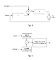
- a first filter F is applied to the main signal and a second filter G is applied to the probe signal, see figure 3 which shows a schematic overview of the matching of a main signal and a probe signal.
- N ⁇ . voice p - F voice m + noise p - F noise m
- the first filter F is arranged so that the filtered voice component of the main signal is roughly equal to the voice component (multiplied by ⁇ ) of the probe signal, i. e.: ⁇ . voice p ⁇ F voice m
- the second filter G is applied to the noise signal N and the output from filter G is subtracted from the main signal (as in figure 4 ) to provide a signal Vnr with a reduced noise content.
- Vnr main - Gout
- Gout G N
- Gout G ⁇ noise p - F noise m
- Vnr voice m + noise m - G ⁇ noise p - F noise m
- the second filter G is arranged so that the output of the second filter G is roughly equal to the noise component of the main signal, when the input is the difference between the noise component of the probe signal and the output of the first filter F of the noise component of the main signal. That is: noise m ⁇ G ⁇ noise p - F noise m
- the scheme of figure 3 thus extracts the voice component of the main signal by suppressing the noise components using a probe signal and applying a first filter F and a second filter G.
- the mobile communication terminal 100 is configured to determine the second filter G by using an adaptation algorithm, such as a Least Mean Squares (LMS) algorithm or a Normalised Least Mean Squares (NLMS) algorithm or an adaptive NLMS algorithm based on minimizing the error between the noise component of the main signal and the G-filtered value of the difference between the noise component of the probe signal and the F-filtered value of the noise component of the main signal.
- LMS Least Mean Squares
- NLMS Normalised Least Mean Squares
- the second filter G is dependent on the noise components and is thus best trained in the absence of any voice input.
- Vnr represents the error between the noise component of the main signal and the filtered value.
- the second filter G can be trained using an adaptation algorithm s discussed above.
- the mobile communication terminal 100 is configured to detect voice activity and to determine when the user is speaking by employing a voice activation scheme.
- One voice activation scheme is to use a slow time constant smoothing of the signal that is compared to a fast time constant smoothing of the same signal. Such voice activation detection works even when the noise level is louder than the voice level.
- the vad (voice activity detection) metric represents an estimation of a voice level.
- the activity metric can be determined from the voice level metric (vad).
- An activity measure can easily be calculated from the voice level in a number of manners.
- the voice activation is determined from the voice level by extracting a Boolean data (1 or 0) by determining if the voice level exceeds a threshold level.
- the voice activation is determined from the voice level by extracting a Boolean data (1 or 0) by determining a voice presence probability through gaining, scaling or clamping.
- Figure 4 shows a schematic view of the voice activity detection.
- a main signal (main) and a probe signal (probe) are passed through a shape extractor.
- the two shapes are subtracted and the voice activity metric is computed as per one of the embodiments described above.
- the mobile communication terminal 100 is thus configured to determine the second filter G when there is no voice by employing a voice activation detection scheme as disclosed in the above.
- N represents an error to adapt the first filter F on.
- the noise is dynamic there will be periods of time when there is no noise present or at least when the noise level is much lower than the voice level. During such time windows it is possible to train the first filter F.
- a threshold on the vad metric expressed before can be a first condition to train the filter F.
- a second condition to meet at same time can be a threshold on the magnitude of the probe signal directly.
- the probe signal has a low quantity of speech so it can furnish a simple approximation of noise presence.
- the parameter ⁇ can be significantly low and if the first filter is close to full adaptation, the gain of filter F would also be low and close to the parameter ⁇ .
- the mobile communication terminal 100 is configured to utilize an adaptation algorithm having a slow adaptation speed which enables to train the filter F even in the presence of noise. It should be noted that even if the first filter F is not yet fully trained the adaptation of the second filter is still possible as it is only performed when there is no speech and the signal(s) only contain noise which will be suppressed efficiently.
- the first filter F is a FIR (Finite Impulse Response) filter.
- the second filter G is a FIR (Finite Impulse Response) filter. FIR filters are useful even when a full adaptation is not possible and will thus provide a satisfactory noise reduction even before full training is achieved.
- the mobile communication terminal 100 is arranged to perform a spectral subtraction of the noise signal N from the voice signal Vnr. See figure 5 which shows a schematic view of the noise reduction scheme. Before the subtraction both the N signal and the Vnr signal transformed to their spectrums, through for example a Fast Fourier Transformation (FFT).
- FFT Fast Fourier Transformation
- the mobile communication terminal 100 may be configured to generate a noise vector that is subtracted from the voice signal Vnr.
- the mobile communication terminal 100 is further configured to generate the noise vector as an adaptive gain vector which is determined when there is no voice input controlled through the voice activation detection. This enables the noise reduction to work even when the noise N does not have a similar spectrum as the noise residue in Vnr and the gain vector is a good estimate of noise residue in the Vnr spectrum.
- the mobile communication terminal 100 may be configured to determine the gain vector through smoothing methods.
- FIG. 6 shows a flowchart for a general method according to one embodiment of the teachings disclosed herein.
- a mobile communication terminal receives a main signal 610 from a first acoustic sensor 160 and receives a probe signal 620 from a second acoustic sensor 150.
- the mobile communication terminal 100 generates 630 a noise signal (N) by subtracting with a first filter (F) filtered said main signal from said probe signal.
- the mobile communication terminal 100 also generates a noise reduced voice signal 640 (Vnr) by subtracting with a second filter (G) filtered noise signal (N) from said main signal, wherein said first filter is adapted based on a voice component of the main signal and the probe signal in the absence or near absence of noise and said second filter is adapted based on the noise components of said main signal and said probe signal when no voice input is present.
- Vnr noise reduced voice signal 640
- G second filter
- N filtered noise signal
- references to 'computer-readable storage medium', 'computer program product', 'tangibly embodied computer program' etc. or a 'controller', 'computer', 'processor' etc. should be understood to encompass not only computers having different architectures such as single /multi- processor architectures and sequential (Von Neumann)/parallel architectures but also specialized circuits such as field-programmable gate arrays (FPGA), application specific circuits (ASIC), signal processing devices and other devices.
- References to computer program, instructions, code etc. should be understood to encompass software for a programmable processor or firmware such as, for example, the programmable content of a hardware device whether instructions for a processor, or configuration settings for a fixed-function device, gate array or programmable logic device etc.
- the mobile communication terminal 100 provides good dynamic noise reduction without needing to implement a specific microphone for noise probing.
- the loudspeaker is simply reused as microphone. It is advantageous on cost perspective but moreover avoids mechanic complexity of placing a second microphone on small or dense phones.
- the manner or scheme itself is efficient on any kind of acoustic sensors without imposing the sources to be matched. This particularity is critical to operate with a speaker used in reverse operation but it remains interesting if a real microphone was used as probe sensor. In such case, the algorithm doesn't require any matching of main and probe microphones and probe microphone can be placed anywhere.
- the algorithm can reduces non-stationary noise down to 0 whatever is noise wave direction. This is a significant advantage compared to beam forming approaches which doesn't offer noise attenuation if noise comes in same direction than user voice.
Landscapes
- Physics & Mathematics (AREA)
- Engineering & Computer Science (AREA)
- Acoustics & Sound (AREA)
- Signal Processing (AREA)
- Health & Medical Sciences (AREA)
- General Health & Medical Sciences (AREA)
- Otolaryngology (AREA)
- Telephone Function (AREA)
Priority Applications (2)
| Application Number | Priority Date | Filing Date | Title |
|---|---|---|---|
| EP20130168424 EP2806424A1 (de) | 2013-05-20 | 2013-05-20 | Verbesserte Rauschunterdrückung |
| US14/283,023 US20140341386A1 (en) | 2013-05-20 | 2014-05-20 | Noise reduction |
Applications Claiming Priority (1)
| Application Number | Priority Date | Filing Date | Title |
|---|---|---|---|
| EP20130168424 EP2806424A1 (de) | 2013-05-20 | 2013-05-20 | Verbesserte Rauschunterdrückung |
Publications (1)
| Publication Number | Publication Date |
|---|---|
| EP2806424A1 true EP2806424A1 (de) | 2014-11-26 |
Family
ID=48534152
Family Applications (1)
| Application Number | Title | Priority Date | Filing Date |
|---|---|---|---|
| EP20130168424 Withdrawn EP2806424A1 (de) | 2013-05-20 | 2013-05-20 | Verbesserte Rauschunterdrückung |
Country Status (2)
| Country | Link |
|---|---|
| US (1) | US20140341386A1 (de) |
| EP (1) | EP2806424A1 (de) |
Families Citing this family (8)
| Publication number | Priority date | Publication date | Assignee | Title |
|---|---|---|---|---|
| JP6264542B2 (ja) * | 2014-01-30 | 2018-01-24 | 任天堂株式会社 | 情報処理装置、情報処理プログラム、情報処理システム、および情報処理方法 |
| US9530433B2 (en) * | 2014-03-17 | 2016-12-27 | Sharp Laboratories Of America, Inc. | Voice activity detection for noise-canceling bioacoustic sensor |
| CN106157967A (zh) | 2015-04-28 | 2016-11-23 | 杜比实验室特许公司 | 脉冲噪声抑制 |
| JP6613267B2 (ja) | 2017-06-02 | 2019-11-27 | 任天堂株式会社 | 情報処理システム、情報処理プログラム、情報処理装置、および、情報処理方法 |
| JP6837921B2 (ja) | 2017-06-02 | 2021-03-03 | 任天堂株式会社 | ゲームプログラム、情報処理装置、情報処理システム、および、情報処理方法 |
| JP6653293B2 (ja) | 2017-06-05 | 2020-02-26 | 任天堂株式会社 | 情報処理システム、情報処理プログラム、情報処理装置、および、情報処理方法 |
| CN112151047B (zh) * | 2020-09-27 | 2022-08-05 | 桂林电子科技大学 | 一种应用于语音数字信号的实时自动增益控制方法 |
| US20220293119A1 (en) * | 2021-03-11 | 2022-09-15 | Aondevices, Inc. | Multistage low power, low latency, and real-time deep learning single microphone noise suppression |
Citations (4)
| Publication number | Priority date | Publication date | Assignee | Title |
|---|---|---|---|---|
| US20040161121A1 (en) * | 2003-01-17 | 2004-08-19 | Samsung Electronics Co., Ltd | Adaptive beamforming method and apparatus using feedback structure |
| US20080170715A1 (en) * | 2007-01-11 | 2008-07-17 | Fortemedia, Inc. | Broadside small array microphone beamforming unit |
| US20110181452A1 (en) * | 2010-01-28 | 2011-07-28 | Dsp Group, Ltd. | Usage of Speaker Microphone for Sound Enhancement |
| US20120123772A1 (en) * | 2010-11-12 | 2012-05-17 | Broadcom Corporation | System and Method for Multi-Channel Noise Suppression Based on Closed-Form Solutions and Estimation of Time-Varying Complex Statistics |
Family Cites Families (5)
| Publication number | Priority date | Publication date | Assignee | Title |
|---|---|---|---|---|
| JPH07202998A (ja) * | 1993-12-29 | 1995-08-04 | Nec Corp | 周囲ノイズ除去機能を備えた電話機 |
| US6963649B2 (en) * | 2000-10-24 | 2005-11-08 | Adaptive Technologies, Inc. | Noise cancelling microphone |
| JP2002281135A (ja) * | 2001-03-21 | 2002-09-27 | Nec Viewtechnology Ltd | 携帯電話 |
| EP2237270B1 (de) * | 2009-03-30 | 2012-07-04 | Nuance Communications, Inc. | Verfahren zur Bestimmung des Geräuschreferenzsignals zur Geräuschkompensation und/oder Geräuschverminderung |
| US9124219B2 (en) * | 2010-07-01 | 2015-09-01 | Conexant Systems, Inc. | Audio driver system and method |
-
2013
- 2013-05-20 EP EP20130168424 patent/EP2806424A1/de not_active Withdrawn
-
2014
- 2014-05-20 US US14/283,023 patent/US20140341386A1/en not_active Abandoned
Patent Citations (4)
| Publication number | Priority date | Publication date | Assignee | Title |
|---|---|---|---|---|
| US20040161121A1 (en) * | 2003-01-17 | 2004-08-19 | Samsung Electronics Co., Ltd | Adaptive beamforming method and apparatus using feedback structure |
| US20080170715A1 (en) * | 2007-01-11 | 2008-07-17 | Fortemedia, Inc. | Broadside small array microphone beamforming unit |
| US20110181452A1 (en) * | 2010-01-28 | 2011-07-28 | Dsp Group, Ltd. | Usage of Speaker Microphone for Sound Enhancement |
| US20120123772A1 (en) * | 2010-11-12 | 2012-05-17 | Broadcom Corporation | System and Method for Multi-Channel Noise Suppression Based on Closed-Form Solutions and Estimation of Time-Varying Complex Statistics |
Also Published As
| Publication number | Publication date |
|---|---|
| US20140341386A1 (en) | 2014-11-20 |
Similar Documents
| Publication | Publication Date | Title |
|---|---|---|
| EP2806424A1 (de) | Verbesserte Rauschunterdrückung | |
| EP3373300B1 (de) | Verfahren und vorrichtung zur verarbeitung eines sprachsignals | |
| US10269369B2 (en) | System and method of noise reduction for a mobile device | |
| KR101444100B1 (ko) | 혼합 사운드로부터 잡음을 제거하는 방법 및 장치 | |
| US9674625B2 (en) | Passive proximity detection | |
| EP2973558B1 (de) | Verfahren zur adaptiven verarbeitung eines akustischen signal mittels der charakterisierung der akustischen umgebung | |
| JP5410603B2 (ja) | マルチチャネル信号の位相ベースの処理のためのシステム、方法、装置、およびコンピュータ可読媒体 | |
| US20190272842A1 (en) | Speech enhancement for an electronic device | |
| US20140037100A1 (en) | Multi-microphone noise reduction using enhanced reference noise signal | |
| EP2449754B1 (de) | Vorrichtung, verfahren und computerprogramm zur steuerung eines akustischen signals | |
| US20150172815A1 (en) | Systems and methods for feedback detection | |
| EP2278356B1 (de) | Vorrichtung und Verfahren zum Erkennen von Nutzungsprofilen in mobilen Vorrichtungen | |
| US11373665B2 (en) | Voice isolation system | |
| US20100098266A1 (en) | Multi-channel audio device | |
| KR20080059147A (ko) | 노이즈 환경에서 스피치 신호의 강건한 분리 | |
| CN109686378B (zh) | 语音处理方法和终端 | |
| KR20210102333A (ko) | 음성 검출을 위한 방법들 및 시스템들 | |
| JP2015513854A (ja) | モバイル通信機器での音声通信エクスペリエンスを向上させるための方法およびシステム | |
| EP2752848B1 (de) | Verfahren und Vorrichtung zur Erzeugung eines rauschreduzierten Audiosignals mithilfe einer Mikrofonanordnung | |
| CN111754969B (zh) | 一种降噪方法、装置、电子设备和降噪系统 | |
| JP6833616B2 (ja) | エコー抑圧装置、エコー抑圧方法及びエコー抑圧プログラム | |
| US10462581B2 (en) | Method of detecting a defect in a hearing instrument, and hearing instrument | |
| CN104581526A (zh) | 传感器 | |
| CN113630708A (zh) | 耳机麦克风异常检测的方法、装置、耳机套件及存储介质 | |
| CN113424558A (zh) | 智能个人助理 |
Legal Events
| Date | Code | Title | Description |
|---|---|---|---|
| PUAI | Public reference made under article 153(3) epc to a published international application that has entered the european phase |
Free format text: ORIGINAL CODE: 0009012 |
|
| 17P | Request for examination filed |
Effective date: 20130520 |
|
| AK | Designated contracting states |
Kind code of ref document: A1 Designated state(s): AL AT BE BG CH CY CZ DE DK EE ES FI FR GB GR HR HU IE IS IT LI LT LU LV MC MK MT NL NO PL PT RO RS SE SI SK SM TR |
|
| AX | Request for extension of the european patent |
Extension state: BA ME |
|
| STAA | Information on the status of an ep patent application or granted ep patent |
Free format text: STATUS: THE APPLICATION IS DEEMED TO BE WITHDRAWN |
|
| 18D | Application deemed to be withdrawn |
Effective date: 20150527 |