EP2920437B1 - Replaceable fluid container - Google Patents
Replaceable fluid container Download PDFInfo
- Publication number
- EP2920437B1 EP2920437B1 EP13798281.5A EP13798281A EP2920437B1 EP 2920437 B1 EP2920437 B1 EP 2920437B1 EP 13798281 A EP13798281 A EP 13798281A EP 2920437 B1 EP2920437 B1 EP 2920437B1
- Authority
- EP
- European Patent Office
- Prior art keywords
- container
- port
- vehicle
- engine
- fluid
- Prior art date
- Legal status (The legal status is an assumption and is not a legal conclusion. Google has not performed a legal analysis and makes no representation as to the accuracy of the status listed.)
- Not-in-force
Links
- 239000012530 fluid Substances 0.000 title claims description 137
- 238000004891 communication Methods 0.000 claims description 50
- 239000000203 mixture Substances 0.000 claims description 32
- 239000010687 lubricating oil Substances 0.000 claims description 27
- 230000008878 coupling Effects 0.000 claims description 17
- 238000010168 coupling process Methods 0.000 claims description 17
- 238000005859 coupling reaction Methods 0.000 claims description 17
- 230000007246 mechanism Effects 0.000 claims description 16
- 238000007789 sealing Methods 0.000 claims description 8
- 239000003921 oil Substances 0.000 description 18
- 238000002485 combustion reaction Methods 0.000 description 17
- 239000007788 liquid Substances 0.000 description 14
- 239000007789 gas Substances 0.000 description 11
- 239000000654 additive Substances 0.000 description 6
- 238000000034 method Methods 0.000 description 5
- 239000000446 fuel Substances 0.000 description 4
- 239000000314 lubricant Substances 0.000 description 4
- 238000012864 cross contamination Methods 0.000 description 3
- 239000002184 metal Substances 0.000 description 3
- 229910052751 metal Inorganic materials 0.000 description 3
- 230000008901 benefit Effects 0.000 description 2
- 230000006835 compression Effects 0.000 description 2
- 238000007906 compression Methods 0.000 description 2
- 238000011109 contamination Methods 0.000 description 2
- KWIUHFFTVRNATP-UHFFFAOYSA-N glycine betaine Chemical compound C[N+](C)(C)CC([O-])=O KWIUHFFTVRNATP-UHFFFAOYSA-N 0.000 description 2
- 230000001050 lubricating effect Effects 0.000 description 2
- 238000004519 manufacturing process Methods 0.000 description 2
- 239000000463 material Substances 0.000 description 2
- 230000000737 periodic effect Effects 0.000 description 2
- 239000004033 plastic Substances 0.000 description 2
- 229920003023 plastic Polymers 0.000 description 2
- 230000000996 additive effect Effects 0.000 description 1
- 229960003237 betaine Drugs 0.000 description 1
- 230000008859 change Effects 0.000 description 1
- 238000004140 cleaning Methods 0.000 description 1
- 239000003599 detergent Substances 0.000 description 1
- 238000001914 filtration Methods 0.000 description 1
- 230000005484 gravity Effects 0.000 description 1
- 150000002484 inorganic compounds Chemical class 0.000 description 1
- 229910010272 inorganic material Inorganic materials 0.000 description 1
- 238000003780 insertion Methods 0.000 description 1
- 230000037431 insertion Effects 0.000 description 1
- 150000002739 metals Chemical class 0.000 description 1
- 239000002480 mineral oil Substances 0.000 description 1
- 235000010446 mineral oil Nutrition 0.000 description 1
- 238000005065 mining Methods 0.000 description 1
- 239000010705 motor oil Substances 0.000 description 1
- 239000002105 nanoparticle Substances 0.000 description 1
- 210000002445 nipple Anatomy 0.000 description 1
- 150000002894 organic compounds Chemical class 0.000 description 1
- 230000036961 partial effect Effects 0.000 description 1
- 230000008569 process Effects 0.000 description 1
- 238000005086 pumping Methods 0.000 description 1
- 239000002516 radical scavenger Substances 0.000 description 1
- 230000002829 reductive effect Effects 0.000 description 1
- 230000000717 retained effect Effects 0.000 description 1
- 230000000979 retarding effect Effects 0.000 description 1
- 150000003839 salts Chemical class 0.000 description 1
- 239000007787 solid Substances 0.000 description 1
- 239000002904 solvent Substances 0.000 description 1
- 230000003068 static effect Effects 0.000 description 1
- 238000003860 storage Methods 0.000 description 1
- XLYOFNOQVPJJNP-UHFFFAOYSA-N water Substances O XLYOFNOQVPJJNP-UHFFFAOYSA-N 0.000 description 1
Images
Classifications
-
- B—PERFORMING OPERATIONS; TRANSPORTING
- B65—CONVEYING; PACKING; STORING; HANDLING THIN OR FILAMENTARY MATERIAL
- B65D—CONTAINERS FOR STORAGE OR TRANSPORT OF ARTICLES OR MATERIALS, e.g. BAGS, BARRELS, BOTTLES, BOXES, CANS, CARTONS, CRATES, DRUMS, JARS, TANKS, HOPPERS, FORWARDING CONTAINERS; ACCESSORIES, CLOSURES, OR FITTINGS THEREFOR; PACKAGING ELEMENTS; PACKAGES
- B65D25/00—Details of other kinds or types of rigid or semi-rigid containers
- B65D25/38—Devices for discharging contents
-
- F—MECHANICAL ENGINEERING; LIGHTING; HEATING; WEAPONS; BLASTING
- F01—MACHINES OR ENGINES IN GENERAL; ENGINE PLANTS IN GENERAL; STEAM ENGINES
- F01M—LUBRICATING OF MACHINES OR ENGINES IN GENERAL; LUBRICATING INTERNAL COMBUSTION ENGINES; CRANKCASE VENTILATING
- F01M1/00—Pressure lubrication
- F01M1/04—Pressure lubrication using pressure in working cylinder or crankcase to operate lubricant feeding devices
-
- B—PERFORMING OPERATIONS; TRANSPORTING
- B65—CONVEYING; PACKING; STORING; HANDLING THIN OR FILAMENTARY MATERIAL
- B65D—CONTAINERS FOR STORAGE OR TRANSPORT OF ARTICLES OR MATERIALS, e.g. BAGS, BARRELS, BOTTLES, BOXES, CANS, CARTONS, CRATES, DRUMS, JARS, TANKS, HOPPERS, FORWARDING CONTAINERS; ACCESSORIES, CLOSURES, OR FITTINGS THEREFOR; PACKAGING ELEMENTS; PACKAGES
- B65D25/00—Details of other kinds or types of rigid or semi-rigid containers
- B65D25/20—External fittings
-
- F—MECHANICAL ENGINEERING; LIGHTING; HEATING; WEAPONS; BLASTING
- F01—MACHINES OR ENGINES IN GENERAL; ENGINE PLANTS IN GENERAL; STEAM ENGINES
- F01M—LUBRICATING OF MACHINES OR ENGINES IN GENERAL; LUBRICATING INTERNAL COMBUSTION ENGINES; CRANKCASE VENTILATING
- F01M11/00—Component parts, details or accessories, not provided for in, or of interest apart from, groups F01M1/00 - F01M9/00
- F01M11/04—Filling or draining lubricant of or from machines or engines
- F01M11/0458—Lubricant filling and draining
-
- H—ELECTRICITY
- H02—GENERATION; CONVERSION OR DISTRIBUTION OF ELECTRIC POWER
- H02K—DYNAMO-ELECTRIC MACHINES
- H02K9/00—Arrangements for cooling or ventilating
- H02K9/19—Arrangements for cooling or ventilating for machines with closed casing and closed-circuit cooling using a liquid cooling medium, e.g. oil
- H02K9/193—Arrangements for cooling or ventilating for machines with closed casing and closed-circuit cooling using a liquid cooling medium, e.g. oil with provision for replenishing the cooling medium; with means for preventing leakage of the cooling medium
-
- F—MECHANICAL ENGINEERING; LIGHTING; HEATING; WEAPONS; BLASTING
- F01—MACHINES OR ENGINES IN GENERAL; ENGINE PLANTS IN GENERAL; STEAM ENGINES
- F01M—LUBRICATING OF MACHINES OR ENGINES IN GENERAL; LUBRICATING INTERNAL COMBUSTION ENGINES; CRANKCASE VENTILATING
- F01M11/00—Component parts, details or accessories, not provided for in, or of interest apart from, groups F01M1/00 - F01M9/00
- F01M11/04—Filling or draining lubricant of or from machines or engines
- F01M2011/0483—Filling or draining lubricant of or from machines or engines with a lubricant cartridge for facilitating the change
Definitions
- This invention relates to replaceable fluid containers for vehicles and engines.
- the invention also relates to an apparatus comprising such a container in fluidic communication with a fluid system and to a vehicle comprising such an apparatus.
- fluids for their operation.
- Such fluids are often liquids.
- internal combustion engines use liquid lubricating oil compositions.
- electric engines use heat exchange liquids for example to cool the engine, to heat the engine or to cool and heat the engine during different operating conditions.
- Such fluids are generally held in reservoirs associated with the engine and may require periodic replacement.
- US patent US 4151823 relates to a quick-change oil filter/reservoir system for an internal combustion engine having a primary oil pump and oil sump comprising a cartridge containing an oil filter element and supply of oil.
- the cartridge is said to be retained on the mounting plate by conventional quick release mountings.
- the tabs and spring clips shown in the embodiment of Figure 1 of US 4151823 are on the end of the cartridge bearing the inlet and outlet ports.
- the breather cap in this embodiment is shown with a pipe connected to the cap.
- US patent US5640936 relates to a removable oil storage and supply tank for a dry sump four cycle internal combustion engine.
- a tank 30 is supported at the bottom by the male portion 62 of three quick disconnect connectors 60. All three oil lines 54, 56 and 58 are said therein to be attached to the tank 30 by quick disconnect fluid connectors 60 which penetrate the bottom of the tank 30.
- a tube 50 is attached to the top of the female member 64 of the connector 60 connected to the oil scavenger line 56.
- a tube 51 is attached to the top of the female member 64 of the connector 60 connected to the oil vent line 58. It is stated therein that this tube 51 extends the vent line 58 into the air space in the tank 30 above the oil level 52 so as to vent the same to the crankcase.
- the oil line 54 through which oil is drawn for lubricating the engine 10, terminates in a quick disconnect fluid connector 60 which includes an oil inlet 67. It is stated therein that this inlet 67 is positioned near the bottom of the tank 30 so that oil will be drawn from the tank even if the oil is reduced to a very low level.
- US patent US6348149 relates to a manufacture for filtering oil. An embodiment is illustrated in Figures 2 to 9 and described at col. 4 line 13 to col. 7 line 44. At col. 5 lines 19 to line 32 quick-disconnect couplings are described. It is stated at col. 5 lines 27 to 31:
- a replaceable fluid container for a vehicle for example a vehicle engine
- the container comprising:
- the vent port is connectable in fluidic communication with the vehicle for example with the fluid system of the engine. Additionally or alternatively, when the engine is an internal combustion engine the vent port is connectable in fluidic communication for example, with an air inlet manifold of the vehicle engine.
- these and other examples of the disclosure facilitate coupling of the reservoir with the fluid system of the vehicle, for example of the vehicle engine.
- these and other examples of the disclosure avoid or at least mitigate the risk of incorrect coupling of inlet ports, outlet ports and vents ports with corresponding ports on a fluid system for example of a vehicle e.g. a vehicle engine fluid system.
- a fluid system for example of a vehicle e.g. a vehicle engine fluid system.
- an apparatus comprising a replaceable fluid container for a vehicle, for example a vehicle engine, the container comprising: a housing comprising a fluid reservoir; an outlet port arranged on the housing to couple the reservoir in fluidic communication with a fluid system of the vehicle for supplying fluid from the reservoir to the vehicle; an inlet port arranged on the housing to couple the reservoir in fluidic communication with the fluid system of the vehicle for receiving fluid from the vehicle to the reservoir; and a vent port arranged on the housing to couple the reservoir in fluidic communication with the vehicle for allowing gas to be passed into and out from the reservoir, wherein the inlet, outlet and vent ports are arranged on a common end of the housing and are arranged such that the distance between the vent port and the nearest of the inlet port and outlet port is greater than the distance between the inlet port and the outlet port, in fluidic communication with a fluid system of a vehicle for example a vehicle engine through the inlet port and outlet port and in fluidic communication with the vehicle through the vent port.
- the vent port is connected in fluidic communication with the vehicle, for example with an engine of the vehicle, for example with the fluid system of the engine. Additionally or alternatively, when the engine is an internal combustion engine the vent port is connected in fluidic communication for example, with an air inlet manifold of the engine.
- a vehicle comprising an apparatus comprising a replaceable fluid container for a vehicle, for example a vehicle engine, the container comprising: a housing comprising a fluid reservoir; an outlet port arranged on the housing to couple the reservoir in fluidic communication with a fluid system of the vehicle for supplying fluid from the reservoir to the vehicle; an inlet port arranged on the housing to couple the reservoir in fluidic communication with the fluid system of the vehicle for receiving fluid from the engine to the reservoir; and a vent port arranged on the housing to couple the reservoir in fluidic communication with the vehicle for allowing gas to be passed into and out from the reservoir, wherein the inlet, outlet and vent ports are arranged on a common end of the housing and are arranged such that the distance between the vent port and the nearest of the inlet port and outlet port is greater than the distance between the inlet port and the outlet port, in fluidic communication with a fluid system of an engine through the inlet port and outlet port and in fluidic communication with the engine through the vent port.
- the vent port is connected in fluidic communication with the vehicle, for example with an engine of the vehicle, for example with the fluid system of the engine. Additionally or alternatively, when the engine is an internal combustion engine the vent port is connected in fluidic communication for example, with an air inlet manifold of the engine.
- the inlet port, the outlet port and the vent port are arranged in a linear radial alignment on the end of the housing.
- the inlet port, the outlet port and the vent port are arranged in a linear radial alignment on the end of the housing and the vent port is arranged radially outermost of the inlet port, outlet port and vent port.
- the inlet port is the radially innermost port
- the outlet port is the radially mid port
- the vent port is the radially outermost port.
- the inlet port, outlet port and vent port are arranged on the end of the housing in non-linear radial alignment such that the radial distance between the vent port and the nearest of the inlet port and outlet port is greater than the radial distance between the inlet port and the outlet port.
- the inlet port, outlet port and vent port are arranged on the end of the housing in non-linear radial alignment such that the radial distance between the vent port and the nearest of the inlet port and outlet port is greater than the radial distance between the inlet port and the outlet port and the vent port is arranged radially outermost of the inlet port, outlet port and vent port.
- the inlet port is the radially innermost port
- the outlet port is the radially mid port
- the vent port is the radially outermost port.
- At least one sealing or separating member is provided around at least one of the ports, for example around all of the ports.
- At least one sealing or separating member is provided between at least two of the ports.
- the inlet port, outlet port and vent port may be arranged on a coupling mechanism.
- the coupling mechanism is arranged such that the container is connectable to couple the reservoir in fluidic communication with the vehicle, for example with an engine of the vehicle, for example with the fluid system of the engine by relative movement between the container and the vehicle and/or engine that is in a linear direction.
- the coupling mechanism is arranged such that the container is connectable to couple the reservoir in fluidic communication with the vehicle, for example with an engine of the vehicle, for example with the fluid system of the engine by relative movement between the container and the vehicle and/or engine that is in a rotational direction.
- the rotation may through an angle of less than 360 degrees, for example through an angle of between 10 degrees and less than 360 degrees, or through an angle of between 10 degrees and 180 degrees, or through an angle of between 10 and 60 degrees, or through an angle of about 25 degrees.
- Each port may comprise a self-sealing port.
- self-sealing ports have the characteristic that when corresponding ports are being connected, a seal is made between the connecting ports before valve or valves open to allow fluid to flow. On disconnection, the valve or valves close to seal off each of the ports before the seal between the ports is broken.
- Suitable valves include spring loaded poppet valves and biased non-return valves.
- Each self-sealing port of the container may provide a "dry break” in which no fluid flows on connection or disconnection of the ports.
- each self-sealing port of the system may provide a "damp break” in which there is flow of only a non-essential amount of fluid, for example a few drips of liquid, on disconnection or connection of the port.
- the inlet port and the outlet port may each or both comprise a non-return valve.
- the vent port does not comprise a non-return valve.
- the container may comprise a key for example a protrusion or recess configured to engage with a complimentary feature of the vehicle and/or engine and/or fluid system. This may further inhibit the container from being coupled to the fluid system unless the ports are in a selected orientation with respect to corresponding ports of the vehicle and/or fluid system and/or engine.
- a key for example a protrusion or recess configured to engage with a complimentary feature of the vehicle and/or engine and/or fluid system. This may further inhibit the container from being coupled to the fluid system unless the ports are in a selected orientation with respect to corresponding ports of the vehicle and/or fluid system and/or engine.
- the container contains a fluid, for example a liquid.
- the liquid may be a liquid for a self-sustaining fluid system for example lubricating oil composition for example an engine lubricating oil composition or a heat exchange fluid for example a heat exchange fluid for an electric engine.
- the liquid may be a liquid for a non-sustaining fluid system, for example deicer, water and/or detergent.
- the reservoir may be a reservoir for a fluid which is a liquid.
- the liquid may be lubricating oil composition, for example lubricating oil composition, or heat exchange fluid for an electric engine.
- the container may be provided as a self-contained system containing fresh, refreshed or unused engine lubricating oil composition which may conveniently replace a container on an engine which container comprises a reservoir containing used or spent engine lubricating oil composition. If the container also comprises a filter, this also is replaced together with the spent or used heat exchange fluid.
- the engine lubricating oil may have heat exchange properties.
- the lubricating oil composition may comprise at least one base stock and at least one lubricating oil additive.
- Suitable base stocks include bio-derived base stocks, mineral oil derived base stocks, synthetic base stocks and semi synthetic base stocks.
- Suitable lubricating oil composition additives for example engine lubricating oil composition additives are known in the art. Examples of additives include organic and/or inorganic compounds.
- the lubricating oil composition comprises about 60 to 90 % by weight in total of base stocks and about 40 to 10 % by weight additives.
- Suitable engine lubricating oil compositions include lubricating oil compositions for internal combustion engines.
- the lubricating oil composition may be a mono-viscosity grade or a multi-viscosity grade engine lubricating oil composition.
- suitable lubricating oil compositions include single purpose lubricating oil compositions and multi-purpose lubricating oil compositions.
- the lubricating oil composition is an engine lubricating oil composition for an internal combustion engine, for example a spark ignition internal combustion engine and/or a compression internal combustion engine.
- the liquid may be a heat exchange fluid for an electric engine.
- the container may be provided as a self-contained system containing fresh, refreshed or unused heat exchange fluid for an electric engine which may conveniently replace a container on an engine which container comprises a reservoir containing used or spent heat exchange fluid. If the container also comprises a filter, this also is replaced together with the spent or used heat exchange fluid.
- Suitable heat exchange fluids for electric engines include aqueous and non-aqueous fluids.
- Suitable heat exchange fluids for electric engines include those which comprise organic and/or non-organic performance boosting additives.
- Suitable heat exchange fluids include be man-made or bio-derived fluids, for example Betaine. According to at least some embodiments, the heat exchange fluids have fire retarding characteristics and/or hydraulic characteristics.
- Suitable heat exchange fluids include phase change fluids.
- Suitable heat exchange fluids include molten metals and salts.
- Suitable heat exchange fluids include nanofluids. Nanofluids comprise nanoparticles suspended in a base fluid, which may be solid, liquid or gas.
- Suitable heat exchange fluids include gases and liquids. Suitable heat exchange fluids include liquefied gases.
- a replaceable fluid container for an engine for example a vehicle engine, the container comprising:
- an apparatus comprising a container as hereindescribed in fluidic communication with the fluid system of a vehicle, for example with the fluid system of a vehicle engine through the inlet port and the outlet port and in fluidic communication with the vehicle for example with an engine of the vehicle through the vent port.
- an apparatus comprising a container as hereindescribed in fluidic communication with the fluid system of an engine, for example a vehicle engine through the inlet port and the outlet port and in fluidic communication with the engine through the vent port.
- a vehicle comprising an apparatus as hereindescribed.
- the engine may be an internal combustion engine. Suitable internal combustion engines include spark ignition internal combustion engines and compression ignition internal combustion engines.
- the engine may be an electric engine.
- Suitable vehicles include motorcycles, earthmoving vehicles, mining vehicles, heavy duty vehicles and passenger cars.
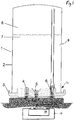
- a container 1 has an housing 2 for example comprised of a plastics material and/or metal. Coupled to the housing 2 is a coupling mechanism 3.
- the coupling mechanism 3 comprises ports 4,5,6 that, in use, engage with a valve mechanism for fluidic communication with a fluid system 12 of an engine, for example a vehicle engine.
- the coupling mechanism 3 may be comprised of a plastics material and/or metal with the ports 4,5,6 formed integral therewith.
- the coupling mechanism 3 may include a quick release component (not shown) for connection to a connector (not shown) on the engine 3.
- the container 1 comprises a reservoir 9 which contains a fluid 7 for the fluid system 12 of the engine 13.
- the reservoir 9 is in fluidic communication with fluid system 12 of the engine 13 for supplying fluid 7 to the engine fluid system 12 through outlet port 5.
- the reservoir 9 is in fluidic communication with fluid system 12 of the engine 13 for receiving fluid 7 from the engine fluid system 12 through inlet port 4.
- a vent port 6 is in fluidic communication with the engine fluid system 13 for allowing gas to be passed into and out from the reservoir 9. Additionally, or alternatively the vent port may be in fluidic communication with an air inlet manifold of an internal combustion engine. This also enables fluid 7 to flow via outlet port 5 under gravity or by pumping when the reservoir is in fluid communication with the engine fluid system 12. Fluid returning to the container 1 may be passed through a filter (not shown).
- the container 1 is supplied as a unit or cartridge and is then connected to the engine so that fluid 7 can be supplied to the engine fluid system through outlet port 5 and received from the engine through inlet port 4.
- the connection to connect the reservoir in fluidic communication with the fluid system of the engine made should be simple and straightforward performed by even an untrained user. In practice it may be performed by relative movement between the container and the engine in a linear direction.
- the coupling mechanism 3 is arranged such that the container is connected to couple the reservoir in fluidic communication with the fluid system of the engine by relative movement between the container and the engine that is in a rotational direction. Opposite movement of the container then enables removal once the container 1 has come to the end of its operational life so that it can be disposed of and a new container 1 provided.
- a separating sealing member or members 10 may be provided to achieve this.
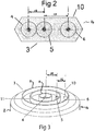
- FIG. 2 This is achieved for example by an arrangement shown in Figure 2 .
- this shows the arrangement of ports 4, 5 and 5 such as might be present in the container of Figure 1 .
- the ports 4, 5, 6 are arranged on a common end 14 of the housing 2 such that the distance 17 between the vent port 6 and the nearest of the inlet port 4 and the outlet port 5 is greater than the distance 18 between the inlet port 4 and the outlet port 5. This ensures that it is not possible for a user to connect the container the wrong way around by inserting it in the wrong direction, or to provide partial connection which enables cross-contamination particularly between the vent port 6 and either of the other ports.
- Figure 3 shows an example for arrangement of ports 4, 5 and 6 on a coupling mechanism 3 which such as shown in Figure 1 .
- the inlet port 4, the outlet port 5 and the vent port 6 are arranged in a linear radial alignment on the end 14 of the housing 2.
- the vent port 6 is arranged radially outermost of the inlet port 4, outlet port 5 and vent port 6.
- the ports, 4, 5, 6 may be arranged in a non-linear radial alignment such that the radial distance 16 between the vent port 6 and the nearest of the inlet port 4 and outlet port 5 is greater than the radial distance 15 between the inlet port and the outlet port.
- the vent port 6 may be arranged radially outermost on the end of the housing 2.
- the inlet port, the outlet port and the vent port may be arranged in a linear radial alignment on the end of the housing, the inlet, outlet and vent ports being arranged on a common end of the housing such that the distance between the vent port and the nearest of the inlet port and outlet port is greater than the distance between the inlet port and the outlet port.
- the coupling mechanism 3 can be connected to couple the reservoir 9 in fluidic communication with the fluid system 12 of the engine 13 by relative movement between the container 1 and the engine 13 that is a rotational direction shown in Figure 3 as arrow A.
- the container may be used with an engine, for example an internal combustion engine or an electric engine.
- the engine may be a vehicle engine.
- a fluid container according to an aspect of the invention could be used in relation to a fluid system of a wide range of apparatus or equipment.
- the fluid container could find application in relation to various static and movable machines, for example industrial machines such as a lathe, or manufacture and assembly equipment, to an engine, or to a vehicle.
- Examples of a fluid container of an aspect of the invention could thus be used to supply lubricant composition to a region of the apparatus or equipment, for example to a region including one or more moving parts, for example a gearbox.
- a fluid container for a wind turbine for example to provide lubricating composition to one or more parts of the wind turbine apparatus.
- the container may supply a lubricant composition to the apparatus, or may supply fluid other than lubricant to the apparatus.
- the fluid may comprise a fuel composition, for example gasoline or diesel
- the container of an aspect of the invention may be for supply the fluid for example to the fuel supply system of the apparatus.
- the container may supply fuel to a vehicle, or tool, for example to a car, motorcycle or lawn mower.
- the container is used to supply a fluid, for example lubricant and/or fuel, to a hand tool, for example a hedge trimmer or leaf blower.
- a fluid for example lubricant and/or fuel
- the fluid may comprise for example an aqueous or other solvent-based composition, for example a cleaning composition.
- the fluid may for example comprise windscreen wash fluid.
- a container of an example of an aspect of the invention may be for supplying fluid to the windscreen washer fluid delivery system for example of a vehicle.
- the fluid system may comprise a fluid circulation system or a fluid delivery system.
Landscapes
- Engineering & Computer Science (AREA)
- Mechanical Engineering (AREA)
- General Engineering & Computer Science (AREA)
- Power Engineering (AREA)
- Lubrication Details And Ventilation Of Internal Combustion Engines (AREA)
- Valves And Accessory Devices For Braking Systems (AREA)
Priority Applications (2)
| Application Number | Priority Date | Filing Date | Title |
|---|---|---|---|
| EP13798281.5A EP2920437B1 (en) | 2012-11-19 | 2013-11-19 | Replaceable fluid container |
| PL13798281T PL2920437T3 (pl) | 2012-11-19 | 2013-11-19 | Wymienny zbiornik na płyn |
Applications Claiming Priority (6)
| Application Number | Priority Date | Filing Date | Title |
|---|---|---|---|
| EP12193246 | 2012-11-19 | ||
| EP13157223 | 2013-02-28 | ||
| EP13157219 | 2013-02-28 | ||
| EP13157220 | 2013-02-28 | ||
| EP13798281.5A EP2920437B1 (en) | 2012-11-19 | 2013-11-19 | Replaceable fluid container |
| PCT/EP2013/074207 WO2014076318A2 (en) | 2012-11-19 | 2013-11-19 | Replaceable fluid container |
Publications (2)
| Publication Number | Publication Date |
|---|---|
| EP2920437A2 EP2920437A2 (en) | 2015-09-23 |
| EP2920437B1 true EP2920437B1 (en) | 2018-04-18 |
Family
ID=49679495
Family Applications (1)
| Application Number | Title | Priority Date | Filing Date |
|---|---|---|---|
| EP13798281.5A Not-in-force EP2920437B1 (en) | 2012-11-19 | 2013-11-19 | Replaceable fluid container |
Country Status (5)
| Country | Link |
|---|---|
| US (2) | US9878822B2 (pl) |
| EP (1) | EP2920437B1 (pl) |
| CN (1) | CN105189949B (pl) |
| PL (1) | PL2920437T3 (pl) |
| WO (1) | WO2014076318A2 (pl) |
Families Citing this family (22)
| Publication number | Priority date | Publication date | Assignee | Title |
|---|---|---|---|---|
| EP2920439B1 (en) | 2012-11-19 | 2017-07-26 | Castrol Limited | Apparatus and method |
| PL2920440T3 (pl) | 2012-11-19 | 2018-01-31 | Castrol Ltd | Wymienny zbiornik płynu |
| CN105026704B (zh) | 2012-11-19 | 2017-08-15 | 卡斯特罗尔有限公司 | 用于发动机的流体容器、促进发动机控制的方法和系统 |
| WO2014076316A2 (en) | 2012-11-19 | 2014-05-22 | Castrol Limited | Apparatus |
| PL2920437T3 (pl) | 2012-11-19 | 2018-09-28 | Castrol Limited | Wymienny zbiornik na płyn |
| GB201409086D0 (en) | 2014-05-21 | 2014-07-02 | Castrol Ltd | Apparatus and method |
| GB201409066D0 (en) | 2014-05-21 | 2014-07-02 | Castrol Ltd | Fluid system |
| GB201409077D0 (en) | 2014-05-21 | 2014-07-02 | Castrol Ltd | Apparatus and method |
| GB201409064D0 (en) | 2014-05-21 | 2014-07-02 | Castrol Ltd | Method and apparatus |
| GB201409065D0 (en) | 2014-05-21 | 2014-07-02 | Castrol Ltd | Fluid system |
| EP3145758A1 (en) | 2014-05-21 | 2017-03-29 | Castrol Limited | Fluid system and method |
| MX364907B (es) | 2014-05-21 | 2019-05-13 | Castrol Ltd | Sistema y método de fluido. |
| GB201409082D0 (en) | 2014-05-21 | 2014-07-02 | Castrol Ltd | Fluid container |
| GB201516854D0 (en) | 2015-09-23 | 2015-11-04 | Castrol Ltd | Fluid system |
| GB2542587A (en) * | 2015-09-23 | 2017-03-29 | Rosanio William | Fluid method and system |
| GB2542586A (en) * | 2015-09-23 | 2017-03-29 | Rosanio William | Fluid method and system |
| GB201516863D0 (en) | 2015-09-23 | 2015-11-04 | Castrol Ltd | Fluid method and system |
| GB201522727D0 (en) | 2015-12-23 | 2016-02-03 | Castrol Ltd | Apparatus and method |
| GB201522732D0 (en) | 2015-12-23 | 2016-02-03 | Castrol Ltd | Apparatus |
| WO2019016167A1 (en) * | 2017-07-17 | 2019-01-24 | Castrol Limited | REPLACEABLE FLUID CONTAINER WITH REMOVABLE COLLECTOR |
| DE102018221257A1 (de) * | 2018-12-07 | 2020-06-10 | Mahle International Gmbh | Vormontage-Baugruppe mit einem Filterelement |
| US20260043349A1 (en) * | 2024-08-06 | 2026-02-12 | Pratt & Whitney Canada Corp. | Air purging arrangement |
Family Cites Families (31)
| Publication number | Priority date | Publication date | Assignee | Title |
|---|---|---|---|---|
| US2817373A (en) | 1955-08-12 | 1957-12-24 | Gilbert & Barker Mfg Co | Portable unit for fluid samples |
| US2976864A (en) | 1957-11-13 | 1961-03-28 | John Ford | Oil purifying apparatus |
| US3246802A (en) | 1962-10-03 | 1966-04-19 | Fuhrmann Heinrich | Lubricant cartridge |
| US3399776A (en) | 1965-09-02 | 1968-09-03 | Robert R. Knuth | Detachable snap-on filter for a hydraulic system |
| US4060105A (en) | 1975-09-11 | 1977-11-29 | Xerox Corporation | Toner loading apparatus with replenishing supply container |
| US4151823A (en) | 1977-07-28 | 1979-05-01 | Grosse Leland J | Quick-change oil filter/reservoir system for internal combustion engine |
| US4676287A (en) | 1984-03-02 | 1987-06-30 | The Regina Company Inc. | Cartridge and docking port for a cleaning device |
| FR2633976B1 (fr) * | 1988-07-08 | 1991-05-31 | Franck Raymond | Dispositif interchangeable de remplissage, prelubrification, filtration et vidange d'huile pour moteurs thermiques |
| US5545354A (en) | 1992-09-01 | 1996-08-13 | The Procter & Gamble Company | Liquid or gel dishwashing detergent containing a polyhydroxy fatty acid amide, calcium ions and an alkylpolyethoxypolycarboxylate |
| MX9305792A (es) | 1992-09-22 | 1994-05-31 | Martinez Velazquez Manuel J | Sistema para facilitar el cambio de aceite y/o del filtro de aceite en motores de combustion. |
| US5454354A (en) | 1994-04-07 | 1995-10-03 | Miller; William | Oil filtering system |
| US5640936A (en) | 1995-04-07 | 1997-06-24 | Brunswick Corporation | Removable oil reservoir for dry sump internal combustion engines |
| US6048454A (en) | 1997-03-18 | 2000-04-11 | Jenkins; Dan | Oil filter pack and assembly |
| KR100282128B1 (ko) | 1999-12-02 | 2001-02-15 | 양윤종 | 윤활유 자동 공급 장치 |
| WO2001053663A2 (fr) | 2000-01-18 | 2001-07-26 | Jacques Benarrouch | Dispositif de cartouche d'huile amovible reliee par un interface de regulation a un moteur a combustion interne pour alimenter ou vidanger manuellement et reculer automatiquement l'huile de lubrification du moteur |
| DE10136971A1 (de) | 2001-07-28 | 2003-02-06 | Daimler Chrysler Ag | Schmiermittelbehälter für eine Trockensumpf-Schmiereinrichtung |
| CN2549181Y (zh) | 2002-06-03 | 2003-05-07 | 姜福生 | 双滤式汽车动力转向油罐 |
| BR0311872A (pt) | 2002-06-12 | 2005-03-15 | Lubriquip Inc | Sistema automático de lubrificação |
| US6793818B1 (en) | 2002-06-19 | 2004-09-21 | Brunswick Corporation | Support and locking structure for a fuel filter |
| DE102005004456B4 (de) | 2005-02-01 | 2010-07-15 | Perma-Tec Gmbh & Co. Kg | Schmierstoffspender |
| US7950547B2 (en) | 2006-01-12 | 2011-05-31 | Millipore Corporation | Reservoir for liquid dispensing system with enhanced mixing |
| US8028672B2 (en) | 2008-02-27 | 2011-10-04 | GM Global Technology Operations LLC | Dry sump oil tank assembly for a vehicle |
| DE102008040748A1 (de) | 2008-07-25 | 2010-01-28 | Hilti Aktiengesellschaft | Schlauchbeutel |
| DE102010027816B4 (de) | 2010-04-15 | 2018-09-13 | Ford Global Technologies, Llc | Brennkraftmaschine mit Ölkreislauf und Verfahren zur Erwärmung des Motoröls einer derartigen Brennkraftmaschine |
| PL2920437T3 (pl) | 2012-11-19 | 2018-09-28 | Castrol Limited | Wymienny zbiornik na płyn |
| PL2920440T3 (pl) | 2012-11-19 | 2018-01-31 | Castrol Ltd | Wymienny zbiornik płynu |
| CN105026704B (zh) | 2012-11-19 | 2017-08-15 | 卡斯特罗尔有限公司 | 用于发动机的流体容器、促进发动机控制的方法和系统 |
| EP2920439B1 (en) | 2012-11-19 | 2017-07-26 | Castrol Limited | Apparatus and method |
| WO2014076316A2 (en) | 2012-11-19 | 2014-05-22 | Castrol Limited | Apparatus |
| DE102012024365B4 (de) | 2012-12-11 | 2014-08-14 | Iav Gmbh Ingenieurgesellschaft Auto Und Verkehr | Verfahren zur Schmiermittelerwärmung einer Brennkraftmaschine |
| JP6114330B2 (ja) | 2015-03-31 | 2017-04-12 | 出光興産株式会社 | 潤滑油組成物及び内燃機関の摩擦低減方法 |
-
2013
- 2013-11-19 PL PL13798281T patent/PL2920437T3/pl unknown
- 2013-11-19 US US14/443,622 patent/US9878822B2/en not_active Expired - Fee Related
- 2013-11-19 WO PCT/EP2013/074207 patent/WO2014076318A2/en not_active Ceased
- 2013-11-19 EP EP13798281.5A patent/EP2920437B1/en not_active Not-in-force
- 2013-11-19 CN CN201380070834.3A patent/CN105189949B/zh not_active Expired - Fee Related
-
2018
- 2018-01-17 US US15/873,891 patent/US10683139B2/en not_active Expired - Fee Related
Non-Patent Citations (1)
| Title |
|---|
| None * |
Also Published As
| Publication number | Publication date |
|---|---|
| PL2920437T3 (pl) | 2018-09-28 |
| US10683139B2 (en) | 2020-06-16 |
| EP2920437A2 (en) | 2015-09-23 |
| US9878822B2 (en) | 2018-01-30 |
| US20150291318A1 (en) | 2015-10-15 |
| CN105189949A (zh) | 2015-12-23 |
| CN105189949B (zh) | 2018-04-24 |
| US20180141720A1 (en) | 2018-05-24 |
| WO2014076318A3 (en) | 2014-07-10 |
| WO2014076318A2 (en) | 2014-05-22 |
Similar Documents
| Publication | Publication Date | Title |
|---|---|---|
| US10683139B2 (en) | Replaceable fluid container | |
| EP2920440B1 (en) | Replaceable fluid container | |
| US9869219B2 (en) | Apparatus and method | |
| US9938867B2 (en) | Cartridge and system for replenishing fluid in an apparatus | |
| US20200291835A1 (en) | Fluid System | |
| EP3145757B1 (en) | Fluid system and method | |
| US9903241B2 (en) | Small air-cooled engine assembly with dry sump lubrication system | |
| US5957240A (en) | Apparatus for engine oil replacement | |
| WO2019170914A1 (en) | Fluid container retaining system and method | |
| GB2545090A (en) | Container and use of container for a fluid reservoir system | |
| WO2019170915A1 (en) | Fluid delivery system | |
| GB2509382A (en) | A deflector to obstruct movement of liquid into a valve of a container for a fluid system in a vehicle |
Legal Events
| Date | Code | Title | Description |
|---|---|---|---|
| PUAI | Public reference made under article 153(3) epc to a published international application that has entered the european phase |
Free format text: ORIGINAL CODE: 0009012 |
|
| 17P | Request for examination filed |
Effective date: 20150508 |
|
| AK | Designated contracting states |
Kind code of ref document: A2 Designated state(s): AL AT BE BG CH CY CZ DE DK EE ES FI FR GB GR HR HU IE IS IT LI LT LU LV MC MK MT NL NO PL PT RO RS SE SI SK SM TR |
|
| AX | Request for extension of the european patent |
Extension state: BA ME |
|
| DAX | Request for extension of the european patent (deleted) | ||
| 17Q | First examination report despatched |
Effective date: 20170104 |
|
| GRAP | Despatch of communication of intention to grant a patent |
Free format text: ORIGINAL CODE: EPIDOSNIGR1 |
|
| INTG | Intention to grant announced |
Effective date: 20180119 |
|
| RIN1 | Information on inventor provided before grant (corrected) |
Inventor name: JEPPS, GARY KEITH Inventor name: MCPHERSON, THOMAS JAMES Inventor name: O'MALLEY, MARK Inventor name: BARNES, ANDREW PHILIP Inventor name: GOODIER, STEVEN PAUL Inventor name: BRETT, PETER STUART Inventor name: HARDING, PIERS SEBASTIAN |
|
| GRAS | Grant fee paid |
Free format text: ORIGINAL CODE: EPIDOSNIGR3 |
|
| GRAA | (expected) grant |
Free format text: ORIGINAL CODE: 0009210 |
|
| AK | Designated contracting states |
Kind code of ref document: B1 Designated state(s): AL AT BE BG CH CY CZ DE DK EE ES FI FR GB GR HR HU IE IS IT LI LT LU LV MC MK MT NL NO PL PT RO RS SE SI SK SM TR |
|
| REG | Reference to a national code |
Ref country code: GB Ref legal event code: FG4D |
|
| REG | Reference to a national code |
Ref country code: CH Ref legal event code: EP |
|
| REG | Reference to a national code |
Ref country code: AT Ref legal event code: REF Ref document number: 990722 Country of ref document: AT Kind code of ref document: T Effective date: 20180515 |
|
| REG | Reference to a national code |
Ref country code: IE Ref legal event code: FG4D |
|
| REG | Reference to a national code |
Ref country code: DE Ref legal event code: R096 Ref document number: 602013036163 Country of ref document: DE |
|
| REG | Reference to a national code |
Ref country code: NL Ref legal event code: FP |
|
| REG | Reference to a national code |
Ref country code: LT Ref legal event code: MG4D |
|
| PG25 | Lapsed in a contracting state [announced via postgrant information from national office to epo] |
Ref country code: ES Free format text: LAPSE BECAUSE OF FAILURE TO SUBMIT A TRANSLATION OF THE DESCRIPTION OR TO PAY THE FEE WITHIN THE PRESCRIBED TIME-LIMIT Effective date: 20180418 Ref country code: AL Free format text: LAPSE BECAUSE OF FAILURE TO SUBMIT A TRANSLATION OF THE DESCRIPTION OR TO PAY THE FEE WITHIN THE PRESCRIBED TIME-LIMIT Effective date: 20180418 Ref country code: NO Free format text: LAPSE BECAUSE OF FAILURE TO SUBMIT A TRANSLATION OF THE DESCRIPTION OR TO PAY THE FEE WITHIN THE PRESCRIBED TIME-LIMIT Effective date: 20180718 Ref country code: SE Free format text: LAPSE BECAUSE OF FAILURE TO SUBMIT A TRANSLATION OF THE DESCRIPTION OR TO PAY THE FEE WITHIN THE PRESCRIBED TIME-LIMIT Effective date: 20180418 Ref country code: LT Free format text: LAPSE BECAUSE OF FAILURE TO SUBMIT A TRANSLATION OF THE DESCRIPTION OR TO PAY THE FEE WITHIN THE PRESCRIBED TIME-LIMIT Effective date: 20180418 Ref country code: FI Free format text: LAPSE BECAUSE OF FAILURE TO SUBMIT A TRANSLATION OF THE DESCRIPTION OR TO PAY THE FEE WITHIN THE PRESCRIBED TIME-LIMIT Effective date: 20180418 Ref country code: BG Free format text: LAPSE BECAUSE OF FAILURE TO SUBMIT A TRANSLATION OF THE DESCRIPTION OR TO PAY THE FEE WITHIN THE PRESCRIBED TIME-LIMIT Effective date: 20180718 |
|
| PG25 | Lapsed in a contracting state [announced via postgrant information from national office to epo] |
Ref country code: RS Free format text: LAPSE BECAUSE OF FAILURE TO SUBMIT A TRANSLATION OF THE DESCRIPTION OR TO PAY THE FEE WITHIN THE PRESCRIBED TIME-LIMIT Effective date: 20180418 Ref country code: LV Free format text: LAPSE BECAUSE OF FAILURE TO SUBMIT A TRANSLATION OF THE DESCRIPTION OR TO PAY THE FEE WITHIN THE PRESCRIBED TIME-LIMIT Effective date: 20180418 Ref country code: GR Free format text: LAPSE BECAUSE OF FAILURE TO SUBMIT A TRANSLATION OF THE DESCRIPTION OR TO PAY THE FEE WITHIN THE PRESCRIBED TIME-LIMIT Effective date: 20180719 Ref country code: HR Free format text: LAPSE BECAUSE OF FAILURE TO SUBMIT A TRANSLATION OF THE DESCRIPTION OR TO PAY THE FEE WITHIN THE PRESCRIBED TIME-LIMIT Effective date: 20180418 |
|
| REG | Reference to a national code |
Ref country code: AT Ref legal event code: MK05 Ref document number: 990722 Country of ref document: AT Kind code of ref document: T Effective date: 20180418 |
|
| PG25 | Lapsed in a contracting state [announced via postgrant information from national office to epo] |
Ref country code: PT Free format text: LAPSE BECAUSE OF FAILURE TO SUBMIT A TRANSLATION OF THE DESCRIPTION OR TO PAY THE FEE WITHIN THE PRESCRIBED TIME-LIMIT Effective date: 20180820 |
|
| PGFP | Annual fee paid to national office [announced via postgrant information from national office to epo] |
Ref country code: NL Payment date: 20181126 Year of fee payment: 6 |
|
| REG | Reference to a national code |
Ref country code: DE Ref legal event code: R097 Ref document number: 602013036163 Country of ref document: DE |
|
| PG25 | Lapsed in a contracting state [announced via postgrant information from national office to epo] |
Ref country code: SK Free format text: LAPSE BECAUSE OF FAILURE TO SUBMIT A TRANSLATION OF THE DESCRIPTION OR TO PAY THE FEE WITHIN THE PRESCRIBED TIME-LIMIT Effective date: 20180418 Ref country code: RO Free format text: LAPSE BECAUSE OF FAILURE TO SUBMIT A TRANSLATION OF THE DESCRIPTION OR TO PAY THE FEE WITHIN THE PRESCRIBED TIME-LIMIT Effective date: 20180418 Ref country code: EE Free format text: LAPSE BECAUSE OF FAILURE TO SUBMIT A TRANSLATION OF THE DESCRIPTION OR TO PAY THE FEE WITHIN THE PRESCRIBED TIME-LIMIT Effective date: 20180418 Ref country code: DK Free format text: LAPSE BECAUSE OF FAILURE TO SUBMIT A TRANSLATION OF THE DESCRIPTION OR TO PAY THE FEE WITHIN THE PRESCRIBED TIME-LIMIT Effective date: 20180418 Ref country code: AT Free format text: LAPSE BECAUSE OF FAILURE TO SUBMIT A TRANSLATION OF THE DESCRIPTION OR TO PAY THE FEE WITHIN THE PRESCRIBED TIME-LIMIT Effective date: 20180418 Ref country code: CZ Free format text: LAPSE BECAUSE OF FAILURE TO SUBMIT A TRANSLATION OF THE DESCRIPTION OR TO PAY THE FEE WITHIN THE PRESCRIBED TIME-LIMIT Effective date: 20180418 |
|
| PGFP | Annual fee paid to national office [announced via postgrant information from national office to epo] |
Ref country code: NO Payment date: 20181217 Year of fee payment: 6 |
|
| PLBE | No opposition filed within time limit |
Free format text: ORIGINAL CODE: 0009261 |
|
| STAA | Information on the status of an ep patent application or granted ep patent |
Free format text: STATUS: NO OPPOSITION FILED WITHIN TIME LIMIT |
|
| PG25 | Lapsed in a contracting state [announced via postgrant information from national office to epo] |
Ref country code: SM Free format text: LAPSE BECAUSE OF FAILURE TO SUBMIT A TRANSLATION OF THE DESCRIPTION OR TO PAY THE FEE WITHIN THE PRESCRIBED TIME-LIMIT Effective date: 20180418 |
|
| PGFP | Annual fee paid to national office [announced via postgrant information from national office to epo] |
Ref country code: FR Payment date: 20181127 Year of fee payment: 6 Ref country code: TR Payment date: 20181107 Year of fee payment: 6 |
|
| 26N | No opposition filed |
Effective date: 20190121 |
|
| PG25 | Lapsed in a contracting state [announced via postgrant information from national office to epo] |
Ref country code: SI Free format text: LAPSE BECAUSE OF FAILURE TO SUBMIT A TRANSLATION OF THE DESCRIPTION OR TO PAY THE FEE WITHIN THE PRESCRIBED TIME-LIMIT Effective date: 20180418 |
|
| REG | Reference to a national code |
Ref country code: CH Ref legal event code: PL |
|
| PG25 | Lapsed in a contracting state [announced via postgrant information from national office to epo] |
Ref country code: LU Free format text: LAPSE BECAUSE OF NON-PAYMENT OF DUE FEES Effective date: 20181119 Ref country code: MC Free format text: LAPSE BECAUSE OF FAILURE TO SUBMIT A TRANSLATION OF THE DESCRIPTION OR TO PAY THE FEE WITHIN THE PRESCRIBED TIME-LIMIT Effective date: 20180418 |
|
| REG | Reference to a national code |
Ref country code: BE Ref legal event code: MM Effective date: 20181130 |
|
| REG | Reference to a national code |
Ref country code: IE Ref legal event code: MM4A |
|
| PG25 | Lapsed in a contracting state [announced via postgrant information from national office to epo] |
Ref country code: LI Free format text: LAPSE BECAUSE OF NON-PAYMENT OF DUE FEES Effective date: 20181130 Ref country code: CH Free format text: LAPSE BECAUSE OF NON-PAYMENT OF DUE FEES Effective date: 20181130 |
|
| PG25 | Lapsed in a contracting state [announced via postgrant information from national office to epo] |
Ref country code: IE Free format text: LAPSE BECAUSE OF NON-PAYMENT OF DUE FEES Effective date: 20181119 |
|
| PG25 | Lapsed in a contracting state [announced via postgrant information from national office to epo] |
Ref country code: BE Free format text: LAPSE BECAUSE OF NON-PAYMENT OF DUE FEES Effective date: 20181130 |
|
| PG25 | Lapsed in a contracting state [announced via postgrant information from national office to epo] |
Ref country code: MT Free format text: LAPSE BECAUSE OF NON-PAYMENT OF DUE FEES Effective date: 20181119 |
|
| PG25 | Lapsed in a contracting state [announced via postgrant information from national office to epo] |
Ref country code: MK Free format text: LAPSE BECAUSE OF NON-PAYMENT OF DUE FEES Effective date: 20180418 Ref country code: CY Free format text: LAPSE BECAUSE OF FAILURE TO SUBMIT A TRANSLATION OF THE DESCRIPTION OR TO PAY THE FEE WITHIN THE PRESCRIBED TIME-LIMIT Effective date: 20180418 Ref country code: HU Free format text: LAPSE BECAUSE OF FAILURE TO SUBMIT A TRANSLATION OF THE DESCRIPTION OR TO PAY THE FEE WITHIN THE PRESCRIBED TIME-LIMIT; INVALID AB INITIO Effective date: 20131119 |
|
| REG | Reference to a national code |
Ref country code: NL Ref legal event code: MM Effective date: 20191201 |
|
| PG25 | Lapsed in a contracting state [announced via postgrant information from national office to epo] |
Ref country code: IS Free format text: LAPSE BECAUSE OF FAILURE TO SUBMIT A TRANSLATION OF THE DESCRIPTION OR TO PAY THE FEE WITHIN THE PRESCRIBED TIME-LIMIT Effective date: 20180818 |
|
| PG25 | Lapsed in a contracting state [announced via postgrant information from national office to epo] |
Ref country code: NL Free format text: LAPSE BECAUSE OF NON-PAYMENT OF DUE FEES Effective date: 20191201 |
|
| PG25 | Lapsed in a contracting state [announced via postgrant information from national office to epo] |
Ref country code: IT Free format text: LAPSE BECAUSE OF NON-PAYMENT OF DUE FEES Effective date: 20191119 Ref country code: FR Free format text: LAPSE BECAUSE OF NON-PAYMENT OF DUE FEES Effective date: 20191130 |
|
| PGFP | Annual fee paid to national office [announced via postgrant information from national office to epo] |
Ref country code: GB Payment date: 20201127 Year of fee payment: 8 Ref country code: DE Payment date: 20201127 Year of fee payment: 8 |
|
| PG25 | Lapsed in a contracting state [announced via postgrant information from national office to epo] |
Ref country code: PL Free format text: LAPSE BECAUSE OF NON-PAYMENT OF DUE FEES Effective date: 20191119 |
|
| REG | Reference to a national code |
Ref country code: DE Ref legal event code: R119 Ref document number: 602013036163 Country of ref document: DE |
|
| PG25 | Lapsed in a contracting state [announced via postgrant information from national office to epo] |
Ref country code: TR Free format text: LAPSE BECAUSE OF NON-PAYMENT OF DUE FEES Effective date: 20191119 |
|
| GBPC | Gb: european patent ceased through non-payment of renewal fee |
Effective date: 20211119 |
|
| PG25 | Lapsed in a contracting state [announced via postgrant information from national office to epo] |
Ref country code: GB Free format text: LAPSE BECAUSE OF NON-PAYMENT OF DUE FEES Effective date: 20211119 Ref country code: DE Free format text: LAPSE BECAUSE OF NON-PAYMENT OF DUE FEES Effective date: 20220601 |