EP2920041B1 - Aufkletterschutz - Google Patents
Aufkletterschutz Download PDFInfo
- Publication number
- EP2920041B1 EP2920041B1 EP13801531.8A EP13801531A EP2920041B1 EP 2920041 B1 EP2920041 B1 EP 2920041B1 EP 13801531 A EP13801531 A EP 13801531A EP 2920041 B1 EP2920041 B1 EP 2920041B1
- Authority
- EP
- European Patent Office
- Prior art keywords
- vertical stop
- fastening
- energy absorbing
- absorbing element
- vertical
- Prior art date
- Legal status (The legal status is an assumption and is not a legal conclusion. Google has not performed a legal analysis and makes no representation as to the accuracy of the status listed.)
- Active
Links
- 230000021715 photosynthesis, light harvesting Effects 0.000 description 20
- 230000009194 climbing Effects 0.000 description 13
- 239000000872 buffer Substances 0.000 description 12
- 238000006073 displacement reaction Methods 0.000 description 9
- 230000035939 shock Effects 0.000 description 3
- 238000005452 bending Methods 0.000 description 2
- 238000010276 construction Methods 0.000 description 2
- 206010012411 Derailment Diseases 0.000 description 1
- 230000015572 biosynthetic process Effects 0.000 description 1
- 230000000694 effects Effects 0.000 description 1
- 230000002452 interceptive effect Effects 0.000 description 1
- 230000002427 irreversible effect Effects 0.000 description 1
- 239000000463 material Substances 0.000 description 1
- 230000009466 transformation Effects 0.000 description 1
Images


Classifications
-
- B—PERFORMING OPERATIONS; TRANSPORTING
- B61—RAILWAYS
- B61G—COUPLINGS; DRAUGHT AND BUFFING APPLIANCES
- B61G11/00—Buffers
- B61G11/16—Buffers absorbing shocks by permanent deformation of buffer element
-
- B—PERFORMING OPERATIONS; TRANSPORTING
- B61—RAILWAYS
- B61D—BODY DETAILS OR KINDS OF RAILWAY VEHICLES
- B61D15/00—Other railway vehicles, e.g. scaffold cars; Adaptations of vehicles for use on railways
- B61D15/06—Buffer cars; Arrangements or construction of railway vehicles for protecting them in case of collisions
-
- B—PERFORMING OPERATIONS; TRANSPORTING
- B61—RAILWAYS
- B61G—COUPLINGS; DRAUGHT AND BUFFING APPLIANCES
- B61G11/00—Buffers
- B61G11/18—Details
Definitions
- the invention relates to a device for preventing the climbing of rail vehicles with a longitudinally extending and inside hollow energy absorbing element, which has an intended for attachment to one of the rail vehicles attachment side and a side remote from the mounting side abutment side, and with a on the abutting side of the energy absorbing element fixed flange having a baffle surface which faces away from the attachment side, wherein the flange projects beyond the contour bounded by the energy dissipation element on its abutting side in at least one vertical direction, so that a retaining web projecting beyond the energy dissipation element is formed.
- Such a device is from the DE 198 33 250 A1 already known.
- a box-like energy absorbing member is provided for receiving a center flange buffer and extends from a mounting side, to which it is attached to a rail vehicle, to a thrust side.
- a flange is attached at the abutting side. This can either be closed or have a circular recess. The recess serves for introducing a center flange buffer into the energy dissipation element, so that only one buffer ram protrudes toward the impact side. A climbing protection is not provided.
- the DE 201 17 536 U1 discloses anti-climb protection for rail vehicles equipped with side buffers.
- the device disclosed therein has an energy dissipation element which is hollow, with a reversibly displaceable buffer plunger extending centrally from the abutting side into the energy dissipation element.
- Above and below the buffer plunger ribs are formed on the abutting side of the energy absorbing element, which are intended to prevent a climbing of the rail vehicles.
- the described climbing protection However, it can only be effective if the height difference between the colliding buffers is low. An enlargement of the entire construction would indeed make it possible to avoid climbing up even with a larger vertical offset of the impact partners. However, the enlargement would lead to a considerable stiffening of the energy dissipation element, thereby achieving a strength that would represent an unacceptable safety risk for the vehicle body.
- Rail vehicles usually have bases with a high strength. On such bases usually constructions are provided with a comparatively low strength. In the case of head-on collisions between two rail vehicles, a vertical offset of the underframes as a result of the collision, in other words an ascent of the rail vehicles, usually leads to drastic damage. In addition, there is a risk of derailment. A climbing of the rail vehicles should therefore be avoided as far as possible.
- baffles with horizontal ribs on the front of rail vehicles.
- the ribs engage with each other, so that the climbing is prevented.
- the prerequisite for this, however, is that the baffle plates can approach each other so far that their ribs engage with each other, so that vertical forces can be transmitted.
- the object of the invention is therefore to provide a device of the type mentioned above, which provides an effective anti-climb protection both for the same and differently equipped rail vehicles.
- the invention solves this problem in that the holding web is equipped at its free end with at least one upstanding from the baffle vertical stop, means for displacing the vertical stop are provided at a shock load in the longitudinal direction.
- a climbing protection which has an irreversibly deformable energy absorbing element, which is equipped with a flange on its abutting side, at which the impact of a colliding rail vehicle is to be expected.
- the flange On its surface facing the colliding rail vehicle, the flange forms a baffle surface which projects beyond the outer contour of the energy dissipation element.
- the intended for the case of collision impact surface is increased in the invention relative to the baffles of prior art devices. Due to the increased impact surface also colliding rail vehicles, which have buffers or energy absorbing elements with a vertical offset, come at their baffles in contact with the baffle of the device according to the invention. The impact energy is therefore introduced according to the invention via the flange effectively into the energy dissipation element.
- the vertical stop which is formed in the invention on the holding web of the flange and that at its free end, prevents climbing up rail vehicles with a smooth baffle. Therefore, the vertical stop unfolds in the context of the invention even at a vertical offset, so a height difference between the abutting energy absorbing elements or buffers its effect.
- the vertical direction extends in each direction, which spans a right angle with said longitudinal direction.
- the vertical direction preferably extends perpendicular to the longitudinal direction, ie the direction of travel of the rail vehicle, downwards and / or upwards.
- the holding web is arranged in the invention at its free end, for example above and / or below the energy dissipation element. He has at least one vertical stop.
- the means for displacing the vertical stop comprise a holding web which is dimensioned so that it is bent in the longitudinal direction of the attachment side with a shock load.
- the vertical stop no longer protrudes from the flat baffle forward. Rather, the retaining bar is bent so far until the tip of the vertical stop with its free end is flying approximately in the plane defined by the impact surface. An interfering effect of the vertical stop is thus prevented.
- the means for displacing the vertical stop fastening means for securing the vertical stop on the retaining web have, which allow for a shock load in the longitudinal direction, a displacement of the vertical stop in the retaining web to the mounting side.
- fastening means hold the vertical stop in or at the free end of the vertical leg in such a way that, in the event of a collision, a displacement of the vertical stop in the retaining bar is made possible.
- the retaining bar does not have to be bent. In other words, the retaining web of the flange due to its dimensions, so for example because of its thickness and its short length have a strength that its bending is prevented in the event of a collision.
- the holding web can therefore - if this is designed with ribs - contribute to preventing the climbing up.
- the said fastening means may in the context of the invention include, for example, a split pin, pin, a screw, rivet fastening with a predetermined breaking point.
- the fastening means provide a clamping fit, wherein when a limit force is exceeded, the displacement of the vertical stop in the holding web is made possible.
- the vertical stop is realized as a stop web extending at right angles to the baffle surface.
- the stop web extends from the baffle surface in the longitudinal direction forward, wherein it is preferably arranged above the energy dissipation element.
- the vertical direction extends from bottom to top.
- the longitudinal direction is equal to the direction of travel of the rail vehicle to which the device according to the invention is attached.
- the baffle protrudes beyond the contour of the energy absorbing element at its abutment side in two mutually remote vertical directions. It is particularly advantageous if the baffle the energy-absorbing element in the mounted state projects beyond the top and bottom.
- the energy dissipation element is basically configured arbitrarily within the scope of the invention. It is particularly advantageous if the energy dissipation element tapers from its attachment side to the abutment side. Here, for example, it is box-shaped or obelisk-shaped.
- the hollow energy-absorbing element has a guide tube which extends in the interior of the energy-absorbing element from its abutting side to the fastening side. It is particularly advantageous if the guide tube is arranged substantially centrally in the energy dissipation element.
- the guide tube is adapted for engagement in a recess provided in the rail vehicle.
- This said recess is preferably formed in a cross member of a chassis or car body.
- the energy-absorbing element is folded accordion-like or compressed. Due to the resulting irreversible material deformation kinetic energy is reduced. This results in the axial displacement of the guide tube to the car body of the rail vehicle, ie in the longitudinal direction.
- the guide tube transmits no forces to the undercarriage or the cross member of the car body. This is avoided by the recess in the rail vehicle.
- the guide tube is used in the context of the invention as an additional anti-climber, since a radial displacement in the vertical direction is prevented.
- guide elements for telescopically extending the guide tube are provided up to the recess.
- the baffle is equipped with ribs.
- the ribs are engageable with the ribs of a colliding rail vehicle and then provide anti-climb protection.
- the invention further relates to a rail vehicle with a device according to one of the preceding claims. Conveniently, the rail vehicle on two of said devices.
- FIG. 1 shows an embodiment of the device 1 according to the invention schematically in a side view.
- the device 1 according to the invention has an energy dissipation element 2, which has a fastening side 3 with which it is fastened to a cross member 4 of a rail vehicle 5.
- the energy absorbing element 2 extends in a longitudinal direction, which coincides with the direction of travel of the rail vehicle 5.
- the energy dissipation element 2 forms a thrust side 6, to which a flange 7 is fastened.
- the flange 7 projects beyond the outer contour of the energy dissipation element 2 on the abutting side 6 with the formation of retaining webs 8 and 9 which extend at right angles to the longitudinal direction, ie upwards or downwards.
- a vertical stop 10 can be seen, which rises from a baffle 11 of the flange 7.
- the vertical stop 10 is realized as a stop web, which extends at right angles to the holding web 8.
- FIG. 2 shows a further embodiment of the device 1 according to the invention, which differs from the in FIG. 1 illustrated embodiment differs only by the configuration of the flange 7.
- the flange 7 projects beyond the contour of the energy dissipation element on the abutting side 6 only in a vertical direction, ie only upwards.
- the vertical stop 10 is held by means of fastening means 12 on the holding web, wherein the fastening means 12 comprise a mounting plate 13 and a rivet connection 14.
- the rivet connection 14 of the vertical stop 10 is fixed to the welded to the flange mounting plate 13. With a sufficiently large impact load in the longitudinal direction, the rivet connection 14 breaks, so that a displacement of the vertical stop 10 in the holding web 8 is made possible for the fastening side 3.
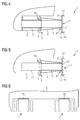
- FIG. 3 shows a further embodiment of the device according to the invention, which differs from the in FIG. 1 shown embodiment differs only in that the lower retaining web 9 is slightly extended and also equipped with a vertical stop 10.
- FIG. 4 shows a further embodiment of the device according to the invention, which differs from the in FIG. 3 shown embodiment differs in that the device 1 comprises a guide tube 15 which extends in the interior of the energy absorbing element 2 from the abutting side 6 from the attachment side 3 out.
- the device 1 comprises a guide tube 15 which extends in the interior of the energy absorbing element 2 from the abutting side 6 from the attachment side 3 out.
- a recess 16 is provided in the cross member 4 of the rail vehicle 5.
- a guide member 17 is arranged in the form of a holding tube.
- the holding tube 17 extends the guide tube 15 telescopically to the recess 16 back.
- the central guide tube 15 arranged in the energy dissipation element and the guide element 17 are connected to one another by a clamping fit.
- the guide tube 15 is displaced into the guide element 17. Due to the telescopic extension, there is an axial guidance of the displacement of the energy dissipation element 2, so that the anti-c
- FIG. 5 embodiment shown corresponds to the in FIG. 4 shown embodiment.
- the holding plate 7 is according to FIG. 5 equipped with ribs 18, which - as has already been stated - can accommodate vertical forces when engaging with other ribs, thus preventing a climbing of collision partners.
- FIG. 6 shows the embodiment according to FIG. 1 in an end view, wherein it can be seen that the rail vehicle equipped with two devices 1, which are each arranged laterally on the rail vehicle 5.
- the inventive device 1 serves as a page buffer.
- FIG. 7 shows a further embodiment of the invention in an incipient collision.
- This in FIG. 7 illustrated embodiment of the device 1 according to the invention differs from the in FIG. 1 illustrated embodiment only in that on the flange 7 ribs 18 are formed.
- FIG. 7 is the collision with a rail vehicle shown with a similar device 1 is equipped.
- a vertical offset between the energy absorbing elements 2 can be seen, in the sense that in FIG. 7 the device shown on the right is arranged slightly higher than the device shown on the left.
- the retaining web 8 of the left-hand device is dimensioned such that it has a thickness and length which makes it possible to bend the retaining web 8 toward the fastening side 3 of the energy-absorbing element 2.
- the ribs 18 of the two flanges 7 can effectively engage each other before irreversibly deforming the energy dissipation member 2, so that effective anti-climb protection is provided.
- FIG. 8 shows that in FIG. 7 illustrated embodiment in collision with a buffer 19, which has a smooth surface 20.
- the smooth surface 20 has no ribs.
- the ribs 18 of the device 1 according to the invention can provide no effective anti-climbing protection.
- the vertical stop 10 an unintentional climbing up the collision partner 19th
- FIG. 9 shows the collision case of two devices according to the in FIG. 2 shown embodiment. It can be seen that the rivet connection 14 is broken by the collision, ie the impact stress of the vertical stop 10 in the longitudinal direction. Thus, a displacement of the vertical stop 10 with respect to the mounting plate 13 is possible, which is firmly welded in the holding web 8. The displacement allows the engagement of the ribs 18 with each other so that effective anti-climbing protection is provided within the scope of the invention.
Priority Applications (1)
| Application Number | Priority Date | Filing Date | Title |
|---|---|---|---|
| PL13801531T PL2920041T3 (pl) | 2012-12-21 | 2013-12-03 | Ochrona przeciwspiętrzeniowa |
Applications Claiming Priority (2)
| Application Number | Priority Date | Filing Date | Title |
|---|---|---|---|
| DE102012224193.0A DE102012224193A1 (de) | 2012-12-21 | 2012-12-21 | Aufkletterschutz |
| PCT/EP2013/075339 WO2014095339A1 (de) | 2012-12-21 | 2013-12-03 | Aufkletterschutz |
Publications (2)
| Publication Number | Publication Date |
|---|---|
| EP2920041A1 EP2920041A1 (de) | 2015-09-23 |
| EP2920041B1 true EP2920041B1 (de) | 2016-11-02 |
Family
ID=49724570
Family Applications (1)
| Application Number | Title | Priority Date | Filing Date |
|---|---|---|---|
| EP13801531.8A Active EP2920041B1 (de) | 2012-12-21 | 2013-12-03 | Aufkletterschutz |
Country Status (7)
| Country | Link |
|---|---|
| US (1) | US9815483B2 (es) |
| EP (1) | EP2920041B1 (es) |
| DE (1) | DE102012224193A1 (es) |
| ES (1) | ES2614278T3 (es) |
| PL (1) | PL2920041T3 (es) |
| RU (1) | RU2637081C2 (es) |
| WO (1) | WO2014095339A1 (es) |
Families Citing this family (4)
| Publication number | Priority date | Publication date | Assignee | Title |
|---|---|---|---|---|
| CN105980230B (zh) * | 2014-02-11 | 2018-05-22 | 西门子公司 | 用于轨道车辆的防爬设备 |
| GB2536888A (en) * | 2015-03-27 | 2016-10-05 | T A Savery & Co Ltd | An energy absorption assembly |
| DE102017214458A1 (de) * | 2017-08-18 | 2019-02-21 | Siemens Aktiengesellschaft | Puffervorrichtung für ein Schienenfahrzeug und Schienenfahrzeug mit derartigen Puffervorrichtungen |
| CN113562014B (zh) * | 2021-08-26 | 2022-11-08 | 中车株洲电力机车有限公司 | 一种自调整防爬吸能装置 |
Family Cites Families (7)
| Publication number | Priority date | Publication date | Assignee | Title |
|---|---|---|---|---|
| DE19833250C2 (de) | 1998-07-23 | 2002-11-07 | Siemens Ag | Energieverzehrelement für Schienenfahrzeuge und Verfahren zur Herstellung eines Energieverzehrelements |
| DE20117536U1 (de) | 2001-10-26 | 2002-01-10 | Siemens Duewag Gmbh | Kletterschutzvorrichtung für Schienenfahrzeuge mit Seitenpuffern |
| CN101517965B (zh) * | 2006-05-01 | 2013-08-21 | 自适应谱与信号定位公司 | 视频流诊断 |
| DE102007005421A1 (de) | 2007-01-30 | 2008-08-07 | Bombardier Transportation Gmbh | Stoßenergieverzehrelement für ein Fahrzeug |
| ES2387126T3 (es) | 2007-09-07 | 2012-09-14 | Ateliers D'orval | Dispositivo anticabalgamiento para vagones de ferrocarril, en particular vagones cisterna |
| AT505870A1 (de) | 2007-09-20 | 2009-04-15 | Siemens Transportation Systems | Crash-modul fur ein schienenfahrzeug |
| DE102008048247B3 (de) | 2008-09-16 | 2009-09-10 | Vossloh Locomotives Gmbh | Aufkletterschutz für Puffer an Lokomotiven |
-
2012
- 2012-12-21 DE DE102012224193.0A patent/DE102012224193A1/de not_active Withdrawn
-
2013
- 2013-12-03 WO PCT/EP2013/075339 patent/WO2014095339A1/de active Application Filing
- 2013-12-03 RU RU2015129718A patent/RU2637081C2/ru active
- 2013-12-03 EP EP13801531.8A patent/EP2920041B1/de active Active
- 2013-12-03 US US14/654,613 patent/US9815483B2/en active Active
- 2013-12-03 ES ES13801531.8T patent/ES2614278T3/es active Active
- 2013-12-03 PL PL13801531T patent/PL2920041T3/pl unknown
Also Published As
| Publication number | Publication date |
|---|---|
| US20160023672A1 (en) | 2016-01-28 |
| PL2920041T3 (pl) | 2017-04-28 |
| DE102012224193A1 (de) | 2014-06-26 |
| RU2637081C2 (ru) | 2017-11-29 |
| US9815483B2 (en) | 2017-11-14 |
| ES2614278T3 (es) | 2017-05-30 |
| WO2014095339A1 (de) | 2014-06-26 |
| RU2015129718A (ru) | 2017-01-27 |
| EP2920041A1 (de) | 2015-09-23 |
Similar Documents
| Publication | Publication Date | Title |
|---|---|---|
| EP1791747B1 (de) | Knautschelement mit führungsmechanismus | |
| EP3526105B1 (de) | Crashstruktur für ein fahrzeug | |
| EP1990251B1 (de) | Energieverzehreinrichtung für mehrgliedrige Fahrzeuge | |
| EP2920041B1 (de) | Aufkletterschutz | |
| EP1049617A1 (de) | Aufprallschutzvorrichtung für schienenfahrzeuge | |
| DE102015209060B4 (de) | Lenksäule für ein Kraftfahrzeug und Energieabsorptionseinrichtung | |
| EP2999609B1 (de) | Schienenfahrzeug mit vollständig eintauchender kupplung | |
| DE102006050028B4 (de) | Vorrichtung an der Fahrzeugfront von Schienenfahrzeugen | |
| DE102016205981A1 (de) | Zug- und Stoßeinrichtung | |
| EP3530544B1 (de) | Deformationsvorrichtung mit aufkletterschutz für schienenfahrzeuge | |
| DE10121354A1 (de) | Vorderwagen für ein Kraftfahrzeug | |
| EP1866194B1 (de) | Schienenfahrzeug mit kollisionstauglicher kupplungsanbindung | |
| DE102005043707A1 (de) | Optimiertes Aufprallsystem für 10°-Lastfall | |
| DE102017206624B4 (de) | Kraftfahrzeug | |
| EP3152094B1 (de) | Schienenfahrzeug mit im bereich seiner front angeordneter kupplung | |
| EP3771609B1 (de) | Hülsenpuffer mit abschnittsweise ummanteltem stössel | |
| EP3071468B1 (de) | Aufkletterschutzvorrichtung für ein schienenfahrzeug | |
| EP2500228B1 (de) | Schienenfahrzeug mit einer Rückholeinrichtung zur Reduzierung des Versatzes zu einem Crashpartner | |
| EP3594082B1 (de) | Crashpuffer mit führungsstange, tragstruktur und schienenfahrzeug | |
| EP3956193B1 (de) | Energieverzehreinrichtung | |
| DE102011102630A1 (de) | Strukturelement für einen Kraftwagenaufbau | |
| AT513364B1 (de) | Schienenfahrzeug mit Crashausrüstung | |
| DE2441939C3 (de) | Lastkraftwagen | |
| DE102005014567A1 (de) | Klappenordnung eines Fahrzeugs mit einer Anhebevorrichtung und einer Fixiereinrichtung | |
| DE102004010791A1 (de) | Lenksäule für ein Kraftfahrzeug als auch damit ausgerüstetes Kraftfahrzeug |
Legal Events
| Date | Code | Title | Description |
|---|---|---|---|
| PUAI | Public reference made under article 153(3) epc to a published international application that has entered the european phase |
Free format text: ORIGINAL CODE: 0009012 |
|
| 17P | Request for examination filed |
Effective date: 20150619 |
|
| AK | Designated contracting states |
Kind code of ref document: A1 Designated state(s): AL AT BE BG CH CY CZ DE DK EE ES FI FR GB GR HR HU IE IS IT LI LT LU LV MC MK MT NL NO PL PT RO RS SE SI SK SM TR |
|
| AX | Request for extension of the european patent |
Extension state: BA ME |
|
| RIN1 | Information on inventor provided before grant (corrected) |
Inventor name: KOERNER, MARCUS Inventor name: TRACHTENHERZ, ALEXANDER |
|
| DAX | Request for extension of the european patent (deleted) | ||
| GRAP | Despatch of communication of intention to grant a patent |
Free format text: ORIGINAL CODE: EPIDOSNIGR1 |
|
| INTG | Intention to grant announced |
Effective date: 20160530 |
|
| GRAS | Grant fee paid |
Free format text: ORIGINAL CODE: EPIDOSNIGR3 |
|
| GRAA | (expected) grant |
Free format text: ORIGINAL CODE: 0009210 |
|
| AK | Designated contracting states |
Kind code of ref document: B1 Designated state(s): AL AT BE BG CH CY CZ DE DK EE ES FI FR GB GR HR HU IE IS IT LI LT LU LV MC MK MT NL NO PL PT RO RS SE SI SK SM TR |
|
| REG | Reference to a national code |
Ref country code: GB Ref legal event code: FG4D Free format text: NOT ENGLISH |
|
| REG | Reference to a national code |
Ref country code: AT Ref legal event code: REF Ref document number: 841507 Country of ref document: AT Kind code of ref document: T Effective date: 20161115 Ref country code: CH Ref legal event code: EP Ref country code: CH Ref legal event code: NV Representative=s name: SIEMENS SCHWEIZ AG, CH |
|
| REG | Reference to a national code |
Ref country code: IE Ref legal event code: FG4D Free format text: LANGUAGE OF EP DOCUMENT: GERMAN |
|
| REG | Reference to a national code |
Ref country code: DE Ref legal event code: R096 Ref document number: 502013005238 Country of ref document: DE |
|
| REG | Reference to a national code |
Ref country code: FR Ref legal event code: PLFP Year of fee payment: 4 |
|
| REG | Reference to a national code |
Ref country code: SE Ref legal event code: TRGR |
|
| PG25 | Lapsed in a contracting state [announced via postgrant information from national office to epo] |
Ref country code: LV Free format text: LAPSE BECAUSE OF FAILURE TO SUBMIT A TRANSLATION OF THE DESCRIPTION OR TO PAY THE FEE WITHIN THE PRESCRIBED TIME-LIMIT Effective date: 20161102 |
|
| REG | Reference to a national code |
Ref country code: NL Ref legal event code: MP Effective date: 20161102 |
|
| REG | Reference to a national code |
Ref country code: LT Ref legal event code: MG4D |
|
| REG | Reference to a national code |
Ref country code: NO Ref legal event code: T2 Effective date: 20161102 |
|
| PG25 | Lapsed in a contracting state [announced via postgrant information from national office to epo] |
Ref country code: LT Free format text: LAPSE BECAUSE OF FAILURE TO SUBMIT A TRANSLATION OF THE DESCRIPTION OR TO PAY THE FEE WITHIN THE PRESCRIBED TIME-LIMIT Effective date: 20161102 Ref country code: NL Free format text: LAPSE BECAUSE OF FAILURE TO SUBMIT A TRANSLATION OF THE DESCRIPTION OR TO PAY THE FEE WITHIN THE PRESCRIBED TIME-LIMIT Effective date: 20161102 Ref country code: GR Free format text: LAPSE BECAUSE OF FAILURE TO SUBMIT A TRANSLATION OF THE DESCRIPTION OR TO PAY THE FEE WITHIN THE PRESCRIBED TIME-LIMIT Effective date: 20170203 |
|
| REG | Reference to a national code |
Ref country code: ES Ref legal event code: FG2A Ref document number: 2614278 Country of ref document: ES Kind code of ref document: T3 Effective date: 20170530 |
|
| PG25 | Lapsed in a contracting state [announced via postgrant information from national office to epo] |
Ref country code: PT Free format text: LAPSE BECAUSE OF FAILURE TO SUBMIT A TRANSLATION OF THE DESCRIPTION OR TO PAY THE FEE WITHIN THE PRESCRIBED TIME-LIMIT Effective date: 20170302 Ref country code: RS Free format text: LAPSE BECAUSE OF FAILURE TO SUBMIT A TRANSLATION OF THE DESCRIPTION OR TO PAY THE FEE WITHIN THE PRESCRIBED TIME-LIMIT Effective date: 20161102 Ref country code: BE Free format text: LAPSE BECAUSE OF NON-PAYMENT OF DUE FEES Effective date: 20161231 Ref country code: HR Free format text: LAPSE BECAUSE OF FAILURE TO SUBMIT A TRANSLATION OF THE DESCRIPTION OR TO PAY THE FEE WITHIN THE PRESCRIBED TIME-LIMIT Effective date: 20161102 Ref country code: IS Free format text: LAPSE BECAUSE OF FAILURE TO SUBMIT A TRANSLATION OF THE DESCRIPTION OR TO PAY THE FEE WITHIN THE PRESCRIBED TIME-LIMIT Effective date: 20170302 |
|
| PG25 | Lapsed in a contracting state [announced via postgrant information from national office to epo] |
Ref country code: EE Free format text: LAPSE BECAUSE OF FAILURE TO SUBMIT A TRANSLATION OF THE DESCRIPTION OR TO PAY THE FEE WITHIN THE PRESCRIBED TIME-LIMIT Effective date: 20161102 Ref country code: RO Free format text: LAPSE BECAUSE OF FAILURE TO SUBMIT A TRANSLATION OF THE DESCRIPTION OR TO PAY THE FEE WITHIN THE PRESCRIBED TIME-LIMIT Effective date: 20161102 Ref country code: DK Free format text: LAPSE BECAUSE OF FAILURE TO SUBMIT A TRANSLATION OF THE DESCRIPTION OR TO PAY THE FEE WITHIN THE PRESCRIBED TIME-LIMIT Effective date: 20161102 Ref country code: SK Free format text: LAPSE BECAUSE OF FAILURE TO SUBMIT A TRANSLATION OF THE DESCRIPTION OR TO PAY THE FEE WITHIN THE PRESCRIBED TIME-LIMIT Effective date: 20161102 |
|
| REG | Reference to a national code |
Ref country code: DE Ref legal event code: R097 Ref document number: 502013005238 Country of ref document: DE |
|
| RAP2 | Party data changed (patent owner data changed or rights of a patent transferred) |
Owner name: SIEMENS AKTIENGESELLSCHAFT |
|
| PG25 | Lapsed in a contracting state [announced via postgrant information from national office to epo] |
Ref country code: BG Free format text: LAPSE BECAUSE OF FAILURE TO SUBMIT A TRANSLATION OF THE DESCRIPTION OR TO PAY THE FEE WITHIN THE PRESCRIBED TIME-LIMIT Effective date: 20170202 Ref country code: SM Free format text: LAPSE BECAUSE OF FAILURE TO SUBMIT A TRANSLATION OF THE DESCRIPTION OR TO PAY THE FEE WITHIN THE PRESCRIBED TIME-LIMIT Effective date: 20161102 |
|
| PLBE | No opposition filed within time limit |
Free format text: ORIGINAL CODE: 0009261 |
|
| STAA | Information on the status of an ep patent application or granted ep patent |
Free format text: STATUS: NO OPPOSITION FILED WITHIN TIME LIMIT |
|
| PG25 | Lapsed in a contracting state [announced via postgrant information from national office to epo] |
Ref country code: MC Free format text: LAPSE BECAUSE OF FAILURE TO SUBMIT A TRANSLATION OF THE DESCRIPTION OR TO PAY THE FEE WITHIN THE PRESCRIBED TIME-LIMIT Effective date: 20161102 |
|
| REG | Reference to a national code |
Ref country code: CH Ref legal event code: PCOW Free format text: NEW ADDRESS: WERNER-VON-SIEMENS-STRASSE 1, 80333 MUENCHEN (DE) |
|
| REG | Reference to a national code |
Ref country code: IE Ref legal event code: MM4A |
|
| 26N | No opposition filed |
Effective date: 20170803 |
|
| PG25 | Lapsed in a contracting state [announced via postgrant information from national office to epo] |
Ref country code: LU Free format text: LAPSE BECAUSE OF NON-PAYMENT OF DUE FEES Effective date: 20161203 |
|
| PG25 | Lapsed in a contracting state [announced via postgrant information from national office to epo] |
Ref country code: SI Free format text: LAPSE BECAUSE OF FAILURE TO SUBMIT A TRANSLATION OF THE DESCRIPTION OR TO PAY THE FEE WITHIN THE PRESCRIBED TIME-LIMIT Effective date: 20161102 Ref country code: IE Free format text: LAPSE BECAUSE OF NON-PAYMENT OF DUE FEES Effective date: 20161203 |
|
| REG | Reference to a national code |
Ref country code: FR Ref legal event code: PLFP Year of fee payment: 5 |
|
| REG | Reference to a national code |
Ref country code: BE Ref legal event code: MM Effective date: 20161231 |
|
| PG25 | Lapsed in a contracting state [announced via postgrant information from national office to epo] |
Ref country code: HU Free format text: LAPSE BECAUSE OF FAILURE TO SUBMIT A TRANSLATION OF THE DESCRIPTION OR TO PAY THE FEE WITHIN THE PRESCRIBED TIME-LIMIT; INVALID AB INITIO Effective date: 20131203 |
|
| PG25 | Lapsed in a contracting state [announced via postgrant information from national office to epo] |
Ref country code: CY Free format text: LAPSE BECAUSE OF FAILURE TO SUBMIT A TRANSLATION OF THE DESCRIPTION OR TO PAY THE FEE WITHIN THE PRESCRIBED TIME-LIMIT Effective date: 20161102 Ref country code: MK Free format text: LAPSE BECAUSE OF FAILURE TO SUBMIT A TRANSLATION OF THE DESCRIPTION OR TO PAY THE FEE WITHIN THE PRESCRIBED TIME-LIMIT Effective date: 20161102 |
|
| GBPC | Gb: european patent ceased through non-payment of renewal fee |
Effective date: 20171203 |
|
| PG25 | Lapsed in a contracting state [announced via postgrant information from national office to epo] |
Ref country code: MT Free format text: LAPSE BECAUSE OF FAILURE TO SUBMIT A TRANSLATION OF THE DESCRIPTION OR TO PAY THE FEE WITHIN THE PRESCRIBED TIME-LIMIT Effective date: 20161102 |
|
| PG25 | Lapsed in a contracting state [announced via postgrant information from national office to epo] |
Ref country code: TR Free format text: LAPSE BECAUSE OF FAILURE TO SUBMIT A TRANSLATION OF THE DESCRIPTION OR TO PAY THE FEE WITHIN THE PRESCRIBED TIME-LIMIT Effective date: 20161102 |
|
| PG25 | Lapsed in a contracting state [announced via postgrant information from national office to epo] |
Ref country code: GB Free format text: LAPSE BECAUSE OF NON-PAYMENT OF DUE FEES Effective date: 20171203 |
|
| REG | Reference to a national code |
Ref country code: DE Ref legal event code: R081 Ref document number: 502013005238 Country of ref document: DE Owner name: SIEMENS MOBILITY GMBH, DE Free format text: FORMER OWNER: SIEMENS AKTIENGESELLSCHAFT, 80333 MUENCHEN, DE |
|
| PGFP | Annual fee paid to national office [announced via postgrant information from national office to epo] |
Ref country code: IT Payment date: 20181218 Year of fee payment: 12 |
|
| REG | Reference to a national code |
Ref country code: CH Ref legal event code: PUE Owner name: SIEMENS MOBILITY GMBH, DE Free format text: FORMER OWNER: SIEMENS AKTIENGESELLSCHAFT, DE |
|
| REG | Reference to a national code |
Ref country code: AT Ref legal event code: PC Ref document number: 841507 Country of ref document: AT Kind code of ref document: T Owner name: SIEMENS MOBILITY GMBH, DE Effective date: 20190506 |
|
| REG | Reference to a national code |
Ref country code: NO Ref legal event code: MMEP |
|
| PG25 | Lapsed in a contracting state [announced via postgrant information from national office to epo] |
Ref country code: AL Free format text: LAPSE BECAUSE OF FAILURE TO SUBMIT A TRANSLATION OF THE DESCRIPTION OR TO PAY THE FEE WITHIN THE PRESCRIBED TIME-LIMIT Effective date: 20161102 |
|
| REG | Reference to a national code |
Ref country code: ES Ref legal event code: PC2A Owner name: SIEMENS MOBILITY GMBH Effective date: 20200805 |
|
| PG25 | Lapsed in a contracting state [announced via postgrant information from national office to epo] |
Ref country code: NO Free format text: LAPSE BECAUSE OF NON-PAYMENT OF DUE FEES Effective date: 20191231 |
|
| PG25 | Lapsed in a contracting state [announced via postgrant information from national office to epo] |
Ref country code: IT Free format text: LAPSE BECAUSE OF NON-PAYMENT OF DUE FEES Effective date: 20211203 |
|
| PGFP | Annual fee paid to national office [announced via postgrant information from national office to epo] |
Ref country code: PL Payment date: 20221125 Year of fee payment: 10 |
|
| PGFP | Annual fee paid to national office [announced via postgrant information from national office to epo] |
Ref country code: ES Payment date: 20230321 Year of fee payment: 10 Ref country code: CH Payment date: 20230307 Year of fee payment: 10 |
|
| PGFP | Annual fee paid to national office [announced via postgrant information from national office to epo] |
Ref country code: DE Payment date: 20230217 Year of fee payment: 10 |
|
| PGFP | Annual fee paid to national office [announced via postgrant information from national office to epo] |
Ref country code: SE Payment date: 20231211 Year of fee payment: 11 Ref country code: FR Payment date: 20231214 Year of fee payment: 11 Ref country code: FI Payment date: 20231220 Year of fee payment: 11 Ref country code: CZ Payment date: 20231127 Year of fee payment: 11 Ref country code: AT Payment date: 20231109 Year of fee payment: 11 |
|
| PGFP | Annual fee paid to national office [announced via postgrant information from national office to epo] |
Ref country code: PL Payment date: 20231124 Year of fee payment: 11 |
|
| PGFP | Annual fee paid to national office [announced via postgrant information from national office to epo] |
Ref country code: ES Payment date: 20240319 Year of fee payment: 11 |