EP2919006B1 - Dispositif et procédé permettant de déterminer la composition d'un mélange de fluides - Google Patents
Dispositif et procédé permettant de déterminer la composition d'un mélange de fluides Download PDFInfo
- Publication number
- EP2919006B1 EP2919006B1 EP15160926.0A EP15160926A EP2919006B1 EP 2919006 B1 EP2919006 B1 EP 2919006B1 EP 15160926 A EP15160926 A EP 15160926A EP 2919006 B1 EP2919006 B1 EP 2919006B1
- Authority
- EP
- European Patent Office
- Prior art keywords
- radiation
- absorption
- bands
- absorption band
- band
- Prior art date
- Legal status (The legal status is an assumption and is not a legal conclusion. Google has not performed a legal analysis and makes no representation as to the accuracy of the status listed.)
- Active
Links
- 239000000203 mixture Substances 0.000 title claims description 62
- 239000012530 fluid Substances 0.000 title claims description 41
- 238000000034 method Methods 0.000 title claims description 16
- 238000010521 absorption reaction Methods 0.000 claims description 129
- 230000005855 radiation Effects 0.000 claims description 129
- XLYOFNOQVPJJNP-UHFFFAOYSA-N water Substances O XLYOFNOQVPJJNP-UHFFFAOYSA-N 0.000 claims description 55
- 229930195733 hydrocarbon Natural products 0.000 claims description 23
- 150000002430 hydrocarbons Chemical class 0.000 claims description 23
- 230000002238 attenuated effect Effects 0.000 claims description 13
- 238000012544 monitoring process Methods 0.000 claims description 7
- 230000004044 response Effects 0.000 claims description 6
- 239000007787 solid Substances 0.000 claims description 3
- 238000000926 separation method Methods 0.000 claims 2
- 239000003921 oil Substances 0.000 description 41
- VNWKTOKETHGBQD-UHFFFAOYSA-N methane Chemical compound C VNWKTOKETHGBQD-UHFFFAOYSA-N 0.000 description 40
- 238000005259 measurement Methods 0.000 description 28
- 239000000523 sample Substances 0.000 description 19
- 230000003595 spectral effect Effects 0.000 description 17
- 230000003287 optical effect Effects 0.000 description 15
- 238000001228 spectrum Methods 0.000 description 14
- 239000004215 Carbon black (E152) Substances 0.000 description 10
- 230000005540 biological transmission Effects 0.000 description 10
- 238000013461 design Methods 0.000 description 10
- 239000012223 aqueous fraction Substances 0.000 description 9
- 238000001514 detection method Methods 0.000 description 7
- 239000007788 liquid Substances 0.000 description 7
- 239000000835 fiber Substances 0.000 description 6
- 239000007789 gas Substances 0.000 description 6
- 238000000862 absorption spectrum Methods 0.000 description 5
- 239000000470 constituent Substances 0.000 description 5
- 239000000463 material Substances 0.000 description 5
- 239000013307 optical fiber Substances 0.000 description 5
- 238000009966 trimming Methods 0.000 description 5
- 230000008033 biological extinction Effects 0.000 description 4
- 230000008901 benefit Effects 0.000 description 3
- 239000003129 oil well Substances 0.000 description 3
- 238000012545 processing Methods 0.000 description 3
- 238000005070 sampling Methods 0.000 description 3
- 102100031702 Endoplasmic reticulum membrane sensor NFE2L1 Human genes 0.000 description 2
- 101000588298 Homo sapiens Endoplasmic reticulum membrane sensor NFE2L1 Proteins 0.000 description 2
- 101000588302 Homo sapiens Nuclear factor erythroid 2-related factor 2 Proteins 0.000 description 2
- 101000577547 Homo sapiens Nuclear respiratory factor 1 Proteins 0.000 description 2
- 102100031701 Nuclear factor erythroid 2-related factor 2 Human genes 0.000 description 2
- 238000011088 calibration curve Methods 0.000 description 2
- 239000000919 ceramic Substances 0.000 description 2
- 230000008859 change Effects 0.000 description 2
- 238000005260 corrosion Methods 0.000 description 2
- 230000007797 corrosion Effects 0.000 description 2
- 239000010779 crude oil Substances 0.000 description 2
- 230000007423 decrease Effects 0.000 description 2
- 230000001419 dependent effect Effects 0.000 description 2
- 238000001658 differential optical absorption spectrophotometry Methods 0.000 description 2
- 230000000694 effects Effects 0.000 description 2
- 229910052736 halogen Inorganic materials 0.000 description 2
- 150000002367 halogens Chemical class 0.000 description 2
- 238000004519 manufacturing process Methods 0.000 description 2
- 239000002245 particle Substances 0.000 description 2
- 239000010453 quartz Substances 0.000 description 2
- 230000009467 reduction Effects 0.000 description 2
- 230000035945 sensitivity Effects 0.000 description 2
- VYPSYNLAJGMNEJ-UHFFFAOYSA-N silicon dioxide Inorganic materials O=[Si]=O VYPSYNLAJGMNEJ-UHFFFAOYSA-N 0.000 description 2
- 238000004088 simulation Methods 0.000 description 2
- 238000001179 sorption measurement Methods 0.000 description 2
- 230000035899 viability Effects 0.000 description 2
- HDMYKJVSQIHZLM-UHFFFAOYSA-N 1-[3,5-di(pyren-1-yl)phenyl]pyrene Chemical compound C1=CC(C=2C=C(C=C(C=2)C=2C3=CC=C4C=CC=C5C=CC(C3=C54)=CC=2)C=2C3=CC=C4C=CC=C5C=CC(C3=C54)=CC=2)=C2C=CC3=CC=CC4=CC=C1C2=C43 HDMYKJVSQIHZLM-UHFFFAOYSA-N 0.000 description 1
- 101100208245 Danio rerio thbs4b gene Proteins 0.000 description 1
- 229910000530 Gallium indium arsenide Inorganic materials 0.000 description 1
- 101000653510 Homo sapiens TATA box-binding protein-like 2 Proteins 0.000 description 1
- 101000659879 Homo sapiens Thrombospondin-1 Proteins 0.000 description 1
- 229910052581 Si3N4 Inorganic materials 0.000 description 1
- 102100030631 TATA box-binding protein-like 2 Human genes 0.000 description 1
- 101150053966 THBS4 gene Proteins 0.000 description 1
- 102100036034 Thrombospondin-1 Human genes 0.000 description 1
- 102100029219 Thrombospondin-4 Human genes 0.000 description 1
- 238000013459 approach Methods 0.000 description 1
- 238000012937 correction Methods 0.000 description 1
- 239000000839 emulsion Substances 0.000 description 1
- 238000002474 experimental method Methods 0.000 description 1
- 238000004880 explosion Methods 0.000 description 1
- 238000010438 heat treatment Methods 0.000 description 1
- 238000005286 illumination Methods 0.000 description 1
- 230000006872 improvement Effects 0.000 description 1
- 230000005764 inhibitory process Effects 0.000 description 1
- 238000009434 installation Methods 0.000 description 1
- 238000011545 laboratory measurement Methods 0.000 description 1
- 238000012423 maintenance Methods 0.000 description 1
- 238000000691 measurement method Methods 0.000 description 1
- 239000002343 natural gas well Substances 0.000 description 1
- 230000007935 neutral effect Effects 0.000 description 1
- 230000000737 periodic effect Effects 0.000 description 1
- 230000008569 process Effects 0.000 description 1
- ZMRUPTIKESYGQW-UHFFFAOYSA-N propranolol hydrochloride Chemical compound [H+].[Cl-].C1=CC=C2C(OCC(O)CNC(C)C)=CC=CC2=C1 ZMRUPTIKESYGQW-UHFFFAOYSA-N 0.000 description 1
- 238000011084 recovery Methods 0.000 description 1
- 230000008439 repair process Effects 0.000 description 1
- 239000004576 sand Substances 0.000 description 1
- HQVNEWCFYHHQES-UHFFFAOYSA-N silicon nitride Chemical compound N12[Si]34N5[Si]62N3[Si]51N64 HQVNEWCFYHHQES-UHFFFAOYSA-N 0.000 description 1
- 238000004611 spectroscopical analysis Methods 0.000 description 1
- 239000000126 substance Substances 0.000 description 1
- 230000001360 synchronised effect Effects 0.000 description 1
- 238000012360 testing method Methods 0.000 description 1
- 230000036962 time dependent Effects 0.000 description 1
- 238000000411 transmission spectrum Methods 0.000 description 1
Images


Classifications
-
- G—PHYSICS
- G01—MEASURING; TESTING
- G01N—INVESTIGATING OR ANALYSING MATERIALS BY DETERMINING THEIR CHEMICAL OR PHYSICAL PROPERTIES
- G01N21/00—Investigating or analysing materials by the use of optical means, i.e. using sub-millimetre waves, infrared, visible or ultraviolet light
- G01N21/17—Systems in which incident light is modified in accordance with the properties of the material investigated
- G01N21/25—Colour; Spectral properties, i.e. comparison of effect of material on the light at two or more different wavelengths or wavelength bands
- G01N21/31—Investigating relative effect of material at wavelengths characteristic of specific elements or molecules, e.g. atomic absorption spectrometry
- G01N21/35—Investigating relative effect of material at wavelengths characteristic of specific elements or molecules, e.g. atomic absorption spectrometry using infrared light
- G01N21/359—Investigating relative effect of material at wavelengths characteristic of specific elements or molecules, e.g. atomic absorption spectrometry using infrared light using near infrared light
-
- G—PHYSICS
- G01—MEASURING; TESTING
- G01N—INVESTIGATING OR ANALYSING MATERIALS BY DETERMINING THEIR CHEMICAL OR PHYSICAL PROPERTIES
- G01N21/00—Investigating or analysing materials by the use of optical means, i.e. using sub-millimetre waves, infrared, visible or ultraviolet light
- G01N21/17—Systems in which incident light is modified in accordance with the properties of the material investigated
- G01N21/25—Colour; Spectral properties, i.e. comparison of effect of material on the light at two or more different wavelengths or wavelength bands
- G01N21/31—Investigating relative effect of material at wavelengths characteristic of specific elements or molecules, e.g. atomic absorption spectrometry
- G01N21/35—Investigating relative effect of material at wavelengths characteristic of specific elements or molecules, e.g. atomic absorption spectrometry using infrared light
- G01N21/3577—Investigating relative effect of material at wavelengths characteristic of specific elements or molecules, e.g. atomic absorption spectrometry using infrared light for analysing liquids, e.g. polluted water
-
- G—PHYSICS
- G01—MEASURING; TESTING
- G01N—INVESTIGATING OR ANALYSING MATERIALS BY DETERMINING THEIR CHEMICAL OR PHYSICAL PROPERTIES
- G01N33/00—Investigating or analysing materials by specific methods not covered by groups G01N1/00 - G01N31/00
- G01N33/26—Oils; viscous liquids; paints; inks
- G01N33/28—Oils, i.e. hydrocarbon liquids
- G01N33/2835—Oils, i.e. hydrocarbon liquids specific substances contained in the oil or fuel
- G01N33/2847—Water in oil
-
- G—PHYSICS
- G01—MEASURING; TESTING
- G01N—INVESTIGATING OR ANALYSING MATERIALS BY DETERMINING THEIR CHEMICAL OR PHYSICAL PROPERTIES
- G01N21/00—Investigating or analysing materials by the use of optical means, i.e. using sub-millimetre waves, infrared, visible or ultraviolet light
- G01N21/17—Systems in which incident light is modified in accordance with the properties of the material investigated
- G01N21/25—Colour; Spectral properties, i.e. comparison of effect of material on the light at two or more different wavelengths or wavelength bands
- G01N21/31—Investigating relative effect of material at wavelengths characteristic of specific elements or molecules, e.g. atomic absorption spectrometry
- G01N2021/3129—Determining multicomponents by multiwavelength light
- G01N2021/3137—Determining multicomponents by multiwavelength light with selection of wavelengths after the sample
-
- G—PHYSICS
- G01—MEASURING; TESTING
- G01N—INVESTIGATING OR ANALYSING MATERIALS BY DETERMINING THEIR CHEMICAL OR PHYSICAL PROPERTIES
- G01N21/00—Investigating or analysing materials by the use of optical means, i.e. using sub-millimetre waves, infrared, visible or ultraviolet light
- G01N21/17—Systems in which incident light is modified in accordance with the properties of the material investigated
- G01N21/25—Colour; Spectral properties, i.e. comparison of effect of material on the light at two or more different wavelengths or wavelength bands
- G01N21/31—Investigating relative effect of material at wavelengths characteristic of specific elements or molecules, e.g. atomic absorption spectrometry
- G01N21/314—Investigating relative effect of material at wavelengths characteristic of specific elements or molecules, e.g. atomic absorption spectrometry with comparison of measurements at specific and non-specific wavelengths
- G01N2021/3148—Investigating relative effect of material at wavelengths characteristic of specific elements or molecules, e.g. atomic absorption spectrometry with comparison of measurements at specific and non-specific wavelengths using three or more wavelengths
-
- G—PHYSICS
- G01—MEASURING; TESTING
- G01N—INVESTIGATING OR ANALYSING MATERIALS BY DETERMINING THEIR CHEMICAL OR PHYSICAL PROPERTIES
- G01N21/00—Investigating or analysing materials by the use of optical means, i.e. using sub-millimetre waves, infrared, visible or ultraviolet light
- G01N21/17—Systems in which incident light is modified in accordance with the properties of the material investigated
- G01N21/25—Colour; Spectral properties, i.e. comparison of effect of material on the light at two or more different wavelengths or wavelength bands
- G01N21/31—Investigating relative effect of material at wavelengths characteristic of specific elements or molecules, e.g. atomic absorption spectrometry
- G01N2021/3185—Investigating relative effect of material at wavelengths characteristic of specific elements or molecules, e.g. atomic absorption spectrometry typically monochromatic or band-limited
- G01N2021/3188—Investigating relative effect of material at wavelengths characteristic of specific elements or molecules, e.g. atomic absorption spectrometry typically monochromatic or band-limited band-limited
-
- G—PHYSICS
- G01—MEASURING; TESTING
- G01N—INVESTIGATING OR ANALYSING MATERIALS BY DETERMINING THEIR CHEMICAL OR PHYSICAL PROPERTIES
- G01N2201/00—Features of devices classified in G01N21/00
- G01N2201/06—Illumination; Optics
- G01N2201/069—Supply of sources
Definitions
- This invention relates to the monitoring of fluids, especially to the determination of the composition of mixtures of fluids.
- the invention is directed in particular to the determination of the composition of a mixture of water and hydrocarbons, but aspects of the invention may be employed with other fluids.
- the invention is particularly applicable to the determination of the water content or "water cut" in an oil natural gas well or an oil pipeline.
- the water may be present naturally in the hydrocarbon stream and may cause corrosion to equipment, so that it may be desirable to ascertain the water fraction of the stream in order to ensure that any corrosion inhibition scheme is adequate.
- the water fraction and oil fraction will typically be determined by near infrared (NIR) absorption, for example by means of a differential optical absorption spectrometer (DOAS) in which the attenuation of radiation at a wavelength of an absorption band characteristic of one component of the mixture is compared with the absorption of a reference wavelength in order to determine the proportion of the relevant component in the mixture.
- NIR near infrared
- DOAS differential optical absorption spectrometer
- US Patent No. 6,292,756 which describes a narrow band infrared water fraction meter in which the infrared radiation is substantially transmitted through the hydrocarbon phase and absorbed by the water phase so that the attenuation of the radiation will give an indication of the water fraction of the mixture.
- WO 2006/129054 A2 discloses a device and method for measuring the fraction of a liquid in a wet gas flow, using one or more light sources emitting at a first wavelength at which the liquid is highly absorbing and emitting at a second wavelength close to the first wavelength and at which the liquid is not highly absorbing. By making use of cross-correlations or known flow rate meters the device can be used as a flow meter.
- a device for determining the composition of a mixture of fluids by spectral absorption, which comprises:
- DOAS is performed with a broadband source and with post-spectral division of the wavelength.
- the broadband source is preferably one that will emit radiation over the entire range of absorption bands that are being investigated, for example in the near infrared (NIR) band from 1 ⁇ m to 2 ⁇ m in the case of hydrocarbon/water mixtures.
- NIR near infrared
- the correction for broadband attenuation is referenced to the transmission at a single wavelength band (e.g.
- the device for separating the radiation is operable to separate the radiation into two reference bands, one reference band located adjacent to each side of the absorption band of one of the fluids.
- the intensity of the noise in the spectrum may not be constant with respect to the wavelength of the radiation across the observed range.
- the degree of scattering is proportional to ⁇ -4 , so that for systems that generate a large degree of scatter, the absorption bands are superposed on a background that slopes with wavelength of the radiation, and so taking a reference for the absorption on one side of the absorption band may lead to a false result.
- a pair of reference wavelengths are employed, one on each side of the absorption band or on each side of a group of absorption bands, it is possible to interpolate the extinction coefficient of the reference wavelengths on either side of the absorption band in order to provide a relatively accurate baseline for the absorption band even where the noise level plot "slopes" with respect to wavelength.
- the device for separating the radiation preferably comprises:
- the device preferably includes a dichroic beam splitter and/or a Rugate filter.
- the latter has multiple reflective and reciprocal transmissive spectral notches as a result of its periodic refractive index variation.
- the device may include a plurality of dichroic beam splitters to split the radiation into a plurality of wavelength bands, the radiation in each wavelength band being split into an absorption band and a reference band having a wavelength range substantially adjacent to the absorption band by means of a Rugate notch or band stop filter.
- the characteristics of the spectroscopic measurement are essentially "hard-wired" in the device, thereby enabling a high degree of precision at relatively low cost.
- R DOAS ⁇ ⁇ r 1 min ⁇ r 1 max ⁇ d ⁇ ⁇ ⁇ + ⁇ ⁇ r 2 min ⁇ r 2 max ⁇ d ⁇ ⁇ ⁇ ⁇ ⁇ m min ⁇ m max ⁇ d ⁇ ⁇ ⁇
- ⁇ is the optical power spectral density (power per unit wavelength). It should be noted that the integral of ⁇ with respect to wavelength gives the optical power in the measurement band, and so R DOAS is equivalent to the power ratio inside the logarithm in Equation (1) above.
- DOAS ratio calibration curves may be derived which allow the fractional volume (and associated error) of each material constituent to be inferred by reference spectrometer data, by integrating the transmitted power spectral density over the relevant molecular absorption and reference bands.
- Any form of spectroscopic instrument used for this type of application is referred to generally as a Spectroscopic Optical Fluid Analyser (SOFA).
- SOFA Spectroscopic Optical Fluid Analyser
- GOR Gas to Oil Ratio GOR
- This may be used advantageously for sub-sea applications at high pressures where the gas is predominantly in solution.
- the measurement of GOR under these conditions eliminates the need for sub-sea sampling and provides data that will indicate the oil shrinkage at the surface separator due to the gas coming out of solution.
- the measurement of GOR of bore hole fluids in exploration also helps establish the viability of a well before opening for full use.
- lamps are preferably chosen with integrated temperature control and which give defined spectral outputs.
- the precise spectrum for each new lamp can be recorded during system setup and also monitored periodically during SOFA experiments.
- These reference spectra can be used for normalising the transmission spectra of the material samples prior to application of the DOAS ratio algorithm.
- temperature control of the LEDs is desirable to maintain repeatable source spectra during sensor operation.
- the spectrum of each LED may be measured with a spectrometer during the build of a new sensor unit.
- the DOAS ratio calibration curves for each sensor unit could be adjusted depending on the values of the peak wavelengths of its constituent LEDs. This could be implemented using a look-up table of calibration adjustment factors calculated during detailed system design. In this way, a routine calibration procedure could be performed during sensor manufacturing to store digitally a set of calibration values in each unit for use throughout its operating lifetime.
- the senor according to a first aspect may be used to obtain a relatively accurate indication of the intensity of the various absorption bands, there remains a problem of processing the signals obtained.
- the signals will in general be superimposed on a background absorption/ scatter signal, which can have a very large dynamic range due to the varying scatter caused by particles and droplets in the mix, which can have a significantly larger dynamic range than the relatively small ratio of the signals.
- the large dynamic range of the signals may be mitigated by the processing architecture chosen. If this were not the case, then an extremely high resolution ADC would be required to cover the full dynamic range of the signals while still being sensitive enough to measure the small difference between the signals. This would be hard to source, expensive, and hard to design.
- a device for outputting the ratio of values of a pair of signals where the value of the individual signals may vary by an amount significantly greater than the ratio of values of the signals, which comprises:
- the two signals may be any signals.
- one of the signals may be a measurand signal, for example a signal defining the intensity of an absorption band of the fluid being monitored, while the other signal may be a reference or background sinal for example the background signal observed on either side of the absorption band.
- one of the signals prefferably be a signal defining the intensity of the absorption band while the other signal is a signal defining the intensity of a different absorption band so that the ratio of the intensities of the two absorption bands may be obtained directly.
- the design of the processor preferably therefore has sufficient bandwidth and dynamic range to cope with the variation of the absolute signals sizes, while still having enough sensitivity to correctly measure the ratio.
- any amplifiers, filters or closed-loop blocks in the architecture are preferably able to respond fast enough to track the change in the background level until the dynamic range has been reduced.
- the ratio of the two signals which is the desired measurement
- changes much more slowly it would be easier and cheaper if this information was presented to the digital circuitry at a speed compatible with the rate of change of the ratio rather than the background.
- the feedback loop includes a filter for setting the gain of the variable-gain amplifier with respect to a reference voltage so that the gain of the variable-gain amplifier is equal to the reference voltage divided by the value of the said one of the signals.
- the amplifier is preferably operable to output both the measurand signal and the background signal, while the feedback loop may be operable to adjust the gain of the amplifier to be inversely proportional to the intensity of the background signal.
- the device may include a plurality of the variable gain amplifiers in cascade, each such variable gain amplifier having a feedback loop.
- the device includes a multiplexer for multiplexing the two signals, for example the detected measurand signal and background signal before they are input to the variable-gain amplifier, and a demultiplexer in the feedback loop for demultiplexing the output of the variable gain amplifier, so that only one of the measurand signal and the background signal is fed back to the amplifier to adjust the gain thereof.
- a method of determining the ratio of values of a pair of signals where the value of the individual signals may vary by an amount significantly greater than the ratio of values of the signals, which comprises:
- the radiation sources employed may have only a limited lifetime, and it is therefore necessary to repair or replace them. It is thus desirable to maximise the lifetime of such radiation sources or the period between replacement, which may be achieved by running them at minimum power. This is particularly desirable for sub-sea applications where there is no routine access for maintenance of the system.
- the output optical power that is required of the radiation source will depend on the measurement bandwidth, which will itself depend on the flow rate of the fluid.
- the invention provides a device for determining the composition of a mixture of fluids that flo along a pipe, which comprises a radiation source for illuminating the mixture with radiation; a detector for detecting radiation that has been attenuated by the mixture; and a device for monitoring the flow rate of fluid along the pipe and outputting a signal indicative of the flow rate; the device including a device for adjusting the intensity of radiation emitted by the radiation source in response to the signal indicative of the flow rate so that the intensity of the radiation source is reduced if the flow rate reduces, so that the radiation source is never run at a power greater than the minimum required for illuminating the mixture with said radiation at a given flow rate.
- lifetime extension using power reduction is relatively small when a quartz halogen source is used, e.g. moving from maximum power to approximately 0.9 times maximum power will increase the life time by nominally x5, after which the lifetime starts to decrease.
- the scope for lifetime extension is however considerably greater when this technique is used in combination with a broad band NIR source synthesised from solid state devices as is discussed below.
- the invention also provides a method of determining the composition of a mixture of fluids that flow along a pipe, which comprises illuminating the mixture with radiation from a radiation source and detecting radiation that has been attenuated by the mixture; monitoring the flow rate of fluid along the pipe; and adjusting the intensity of radiation emitted by the radiation source in response to the flow rate determined so that the intensity of the radiation source is reduced if the flow rate reduces, so that the radiation source is never run at a power greater than the minimum required for illuminating the mixture with said radiation at a given flow rate.
- output power of the radiation source may be controlled under feedback from the flow measurement so that it is never run at a power greater than the minimum required for satisfactory operation at a given flow rate.
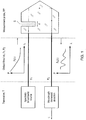
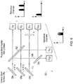
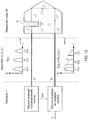
- FIG 1 is a schematic representation of a spectroscopic optical fluid analyser (SOFA) probe in which a spectrally broadband input source light distribution, P i ( ⁇ ), is generated by transceiver T and sent along an optical fibre link F 1 to a Single Side Transmission (SST) retro-reflective measurement probe RP that is immersed in the specimen S.
- the SST probe may be replaced by a double sided transmission probe depending on the specific installation.
- the specimen is constrained to a depth d in the flow channel of the probe. After absorption of the radiation by the specimen, the radiation is reflected by the head of the probe and returned to the detector of the transceiver T by a second optical fibre F 2 .
- a conventional spectrometer may be used for general detection and measurement of the absorption spectra as, for example, in a utility test system.
- a general spectrometer is preferably replaced, for reasons discussed above, by a component specific DOAS/rugate detection unit shown in figures 3 and 4 described below.
- the probe shown in figure 1 may employ a broadband radiation source derived, for example, from a conventional spectrally broadband incandescent source such as a quartz halogen lamp, or alternatively the broadband source may be synthesized by combining radiation from different sources.
- a broadband radiation source derived, for example, from a conventional spectrally broadband incandescent source such as a quartz halogen lamp, or alternatively the broadband source may be synthesized by combining radiation from different sources.
- radiation from a plurality of narrowband sources such as LEDs, super luminescent light emitting diodes (SLEDs),or thermorestive sources may be superimposed using a dichroic beam combiner, or any other suitable means for combining beams and coupled into the illumination optical fibre.
- SLEDs super luminescent light emitting diodes
- thermorestive sources may be superimposed using a dichroic beam combiner, or any other suitable means for combining beams and coupled into the illumination optical fibre.
- Such sources will couple less power into the fibre than a conventional lamp, and therefore may require the system to measure more slowly, they do have intrinsically longer lifetimes than which makes them suitable for applications such as sub-sea or subterranean measurement where the light source cannot be changed routinely. They may also be employed in other applications where the light source cannot easily be changed, for instance where the device is enclosed in a sealed unit that may be provided to prevent the risk of fire or explosion due to the presence of the hydrocarbon gases. They are also particularly suitable for life time extension using the modulation of the output power in response to variations in flow rate as discussed earlier.
- Yet another form of radiation source is a rugged incandescent ceramic radiation source, for example using a silicon nitride heating element. Such sources are compact, mechanically robust and low cost and emit radiation at wavelengths from 1 to 2 ⁇ m. They may typically be employed as gas igniters in domestic cookers and hobs.
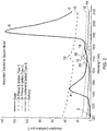
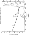
- Figure 2 is an absorption spectrum that is typical for a mixture of hydrocarbons, optionally including gaseous hydrocarbons, and water that may be obtained in the bore of an oil well.
- the absorption spectrum may be made up of spectra from a number of components of the mixture. For example, spectrum 2 that is due to water exhibits an absorption peak 4 at approximately 1450nm and extending from about 1400 to 1530 nm, and a second, larger, absorption peak at approximately 1930nm.
- curve 10 is the spectrum for filtered and shaken oil which may contain a number of small bubbles, for example containing air or gaseous hydrocarbons, that contribute to scattering of the radiation.
- Curve 12 is the spectrum for filtered and settled oil which has a significantly lower baseline due to the lack of air bubbles
- curve 14 is the spectrum of unfiltered and settled oil (type 3) with a relatively low baseline.
- Each of the spectra exhibits a hydrocarbon absorption peak 16 at approximately 1730 nm, extending from about 1700 to 1750 nm.
- the baseline of the curves is not flat, but is significantly larger at shorter wavelengths.
- curve 18 is the spectrum for methane or other low molecular weight gaseous hydrocarbons.
- This curve exhibits an absorption peak at approximately 1670 nm extending from about 1650 to 1690 nm.
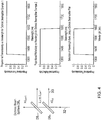
- FIG 3 is a schematic view showing the principle in which typical filter and Rugate wavelength bands (as indicated as a guideline below) enable referenced measurements of the NIR absorption bands of water, methane and oil defined above.
- This device comprises a series of dichroic beam splitters DB 1 to DB 4 that split a beam 32 of radiation from a spectrally broadband source (not shown) into a number of beams 34 to 40 of different wavelengths.
- the light from this source is first delivered to the measurement fluid by the optical fibre F1 and then delivered at 32 in Figure 3 by the fibre F2 as shown in Figure 1 after being spectrally modulated as a result of spectral absorption by the by the measurement fluid.
- a broadband radiation source is passed to a first dichroic beam splitter DB n that transmits radiation of wavelength greater that a specified value ⁇ n , in this case 1345nm, and reflects radiation of a wavelength below that value into beam 33.
- the transmitted beam is then sent to dichroic beam splitter DB n+1 that transmits radiation of wavelength greater than a second wavelength ⁇ n+ , in this case greater than 1590nm, and reflects radiation of wavelength less than ⁇ n+1 so that the radiation reflected by the second beam splitter will have a wavelength from 1345 to 1590nm.
- the original beam is split into four beams having wavelengths less than 1345nm, 1345 to 1590nm, 1590 to 1690nm and 1690 to 1825nm respectively.
- the first beam 34 of wavelength less than 1345nm is an overall reference channel which may be bandwidth limited by an additional notch filter F r , and provides an auxiliary, non-resonant adsorption reference at nominally 1300nm as required.
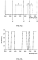
- the remaining beams 36, 38 and 40 each have wavelengths corresponding to an absorption band of interest and also wavelengths that are outside, but adjacent to, the absorption bands. These beams are passed to a Rugate beam splitter 42 having a characteristic shown schematically in figure 5 (a) and (b) .
- any optical notch filter having the appropriate characteristic may be employed, for example a dielectric quarter-wave stack, but Rugate notch filters have the advantage that they exhibit significantly lower amplitude higher-order harmonic structure in the Rugate notch.
- the Rugate notch filter 42 will reflect that part of beam 36 having wavelengths of 1400 to 1530nm, shown as region A in figure 5a , corresponding to the water absorption band, into detector D 2a and transmit the remaining parts of the beam, i.e. of wavelength 1345 to 1400nm and 1530 to 1590nm into detector D 2r to provide a reference.
- the Rugate notch filter will reflect that part of beam 38 having wavelengths of 1650 to 1690nm, shown as region B in figure 5a corresponding to the gaseous hydrocarbon (methane) absorption band, into detector D 3a while transmitting the remaining parts of the beam into the reference detector D 3r .
- the Rugate notch filter will reflect that part of beam 40 having wavelengths of 1700 to 1750nm, shown as region C in figure 5a , corresponding to the oil absorption band, into detector D 4a , while transmitting the remaining parts of the beam, i.e. of wavelengths 1690 to 1700nm and 1750 to 1800nm into reference detector D 4r .
- the device allows the intensity of the radiation attenuated by the water, methane and oil bsorption bands respectively to be detected, and to detect the intensity of non-resonant reference signals on each side of the absorption bands.
- the above wavelengths give a general indication of those that would be used specifically for DOAS water, methane and oil measurement. They may in practice be modified for optimum operation and in particular may be modified to enable the measurement of water using the absorption band centred at nominally 1950nm. The wavelengths will be changed entirely when the same general principle is used for the measurement of different molecular constituents.
- the values for attenuation of the radiation detected by the reference detectors on either side of the absorption bands may simply be averaged in order to provide a baseline for the absorption bands.
- the baseline for the absorption bands may not be the same for each band.
- the baseline for the absorption may not be horizontal but may be formed as a straight-line interpolation of the intensity measured by the reference detector on either side of the absorption band.
- one or more Rugate filters may be used to divide the original beam into beams of different wavelengths and the separate beams may be passed to one or more dichroic beam splitters or to a further Rugate filter that is different from the first Rugate filter in order to form separate absorption and reference beams.
- dielectric quarter-wave stacks instead of rugate notch filters as mentioned above.
- the reference detectors detect the radiation intensity onboth sides of each absorption peak. It is possible, for example for the reference detectors to detect the radiation on each side of a pair of absorption bands or on each side of all three absorption bands and to average or interpolate the baseline if necessary using the reference signals.
- Figure 6 shows an alternative arrangement in which reference absorption is detected on each side of a pair of absorption bands.
- the purpose of this arrangement is to simplify the design of the Rugate by reducing the number of spectral notches.
- the original broadband radiation beam 32 is split by three dichroic beam splitters DB 1 to DB 3 into beams 60, 62 and 64, the first of which has a wavelength less than ⁇ 1 (1345nm) and is filtered by a notch filter F r as described above to provide an auxiliary, non-resonant absorption reference at nominally 1300nmas required.
- the transmitted beam is split by beam splitter DB 2 to reflect radiation of wavelength less than ⁇ 2 (1590nm) and is passed to the rugate beam splitter 62 in the manner described above in order to split the radiation so that radiation having a wavelength of 1400 to 1530nm corresponding to the water absorption band can be detected by detector D 2a and reference bands having wavelengths of 1345 to 1400nm and 1530 to 1590nm are detected by detector D 2r as described above.
- dichroic beam splitter DB 4 which reflects radiation of wavelength below ⁇ 4 (1825nm) corresponding to both the oil and gaseous hydrocarbon component absorption bands onto the rugate beam splitter 62. Radiation of wavelength below 1650nm and above 1750nm is transmitted by the Rugate beam splitter 62, into detector D 3r to detect the reference background radiation intensity on each side of the pair of absorption bands for oil and gaseous hydrocarbons.
- Beam 64 that is reflected by the rugate beam splitter 62 and has wavelengths of from 1650 to 1750nm is passed to dichroic beam splitter DB 3 that reflects radiation of wavelength below ⁇ 3 (1690nm), corresponding to the methane absorption band, into detector D 3a1 and transmits radiation of wavelength above ⁇ 3 corresponding to the oil absorption band, into detector D 3a2 .
- an identical source and detection system may be used in combination with other designs of probe such as double pass transmission and ATR (Attenuated Total-internal Reflection).
- a compact spatial light modulator may be used in which a digital mirror device (DMD) provides an intrinsically high speed and hgh contrast on/off ratio. This is shown in principle in figure 7a and figure 7b .
- lens L 1 forms an image of the output aperture of the source S in the plane of the aperture L 2 via reflection of the beam by the DMD, and L 2 images the output aperture of L 1 in the plane of the output optical fibre F that couples light to the sensor probe immersed in the fluid.
- the apertures and focal lengths of L 1 and L 2 are chosen to match optimally the phase volume of the source to that of the fibre.
- the light field coupled into the output fibre is modulated by simultaneously switching all of the mirrors in the array between the + ⁇ and - ⁇ position corresponding to the on state in which the radiation is coupled into the output fibre F and the off state in which the light is reflected into a beam dump D.
- the modulation rate may be as high as 6.5kHz or more by virtue of the DMD.
- the DMD may be employed with any form of incandescent light source, but it is particularly convenient to use it with the ceramic radiation source referred to above.
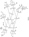
- an image of the light field 32 at the aperture of the input fibre connected to the probe output is formed at the detector apertures S1 to S5 by selected lenses in the lens chain L1 to L8 and hence via transmission and reflection at selected filters and Rugates within this chain.
- the light first passes through NRF1 and then NRF2 via the broadband, high efficiency front reflecting mirrors IM to be incident on the long pass filter LP1.
- the purpose of the filters NRF1 and NRF2 is to reject low and high out of band spectral noise at the sensor input.
- the long wavelength component of the light transmitted by LP1 passes to the Rugate filter R1 where it is divided into the transmitted and reflected components.
- the former forms the reference bands for the oil/methane measurement after transmission through the trimming short pass filter TSP1 which suppresses the longer wavelengths present.
- the latter is reflected by the double sided mirror DM via lens L4.
- Light reflected by the mirror DM is again reflected by the Rugate R1 and mirror DM before being passed to low pass filter LP2 which transmits light of wavelength of the oil absorption band to the trimming band pass filter TPB3 which spectrally limits light of the oil absorption band, and finally to sensor S3 for detecting the oil concentration.
- Light reflected by the low pass filter LP2 has a wavelength corresponding to the methane absorption band and is passed to the trimming band pass filter TBP2 and hence to sensor S2 for determining the amplitude of the methane peak.
- the senor may be configured to measure either methane and oil combined at detector S2/3 by an optical flat, broadband anti-reflection element coated on both faces which has a high transmission for both methane and oil absorption bands, or to measure oil at detector S2 and methane at detector S2 by the use of the low pass filter LP2.
- the Rugate R1 and the double sided front mirror DM may be separated by a significant distance, for example in the range of 30 to 50mm so that the light beams will be spaced apart laterally by a sufficient distance to enable detectors S1 and S2 or S3 to be used, and to enable different detectors S4 and S5 to be used while keeping the angle of incidence of the light rays at the various filters and mirrors at a low value of about 15°.
- Figure 9 shows the concatenated spectral transmissivity of each of the channels S1 to S5 of the arrangement shown in Figure 8 obtained by multiplying the spectral reflectances/transmissivities of each component within a given channel.
- the transmissivity peak for the detector S5 (1400 to 1510nm) corresponding to water absorption is bounded on each side by transmissivity peaks at 1300 to 1380nm and at 1510 to 1590nm for the detector S4 which peaks are used as references for the water detection peak observed by detector S5.
- detector S2 has a transmissivity peak at 1650 to 1690nm, which detects the presence of methane
- detector S3 has a transmissivity peak at 1700 to 1750nm which detects the presence of oil.
- This pair of transmissivities is bounded by a pair of transmissivity peaks occurring at 1590 to 1650nm and at about 1770 to 1850nm which are used as references for determining the value of the methane and oil absorption peaks.
- the arrangement enables the reference bands employed to determine the intensity of the water and the hydrocarbon absorption bands to abut the bands, and the peak value for the transmissivity values for the references will normally be not more than 150nm and especially not more than 100nm from the peak value for the absorption bands.
- a general aim is to make the reference beams symmetrical about the absorption bands in order to minimise errors due to the spectral gradient of the background signal.
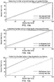
- FIG. 10 The improvement in accuracy obtained by local referencing, i.e. by determining the absorption due to the presence of water and hydrocarbons with reference to the absorption at a wavelength that is adjacent to the absorption peaks is shown in figures 10 and 11.
- Figure 10c is a similar graph showing the values for low and high background scatter obtained using a system that employs a remote reference as in US patent No. 6,292,756 .
- the dotted straight line in each of the graphs extending linearly from 0% to 100% measured and reference water cut shows the actual value of the water cut.
- the upper two graphs, demonstrating a system with local referencing, have an error in the water cut value due to the presence of scatter background which is less than 4% even when obtained with high background scatter, whereas the equivalent error in the water cut value using a system with remote referencing is in excess of 40%.
- the output departs from the "truth" line (where the measured water cut is equal to the reference water cut).
- the close correlation between the outputs shown in figures 10a and 10b obtained respectively for the theoretical and manufactured spectral transmissivity of the filters (c.f. figure 9 ) demonstrates the practical feasibility of the overall system.
- the measurement probe While it is preferred for the measurement probe to employ a broadband radiation source, either formed from a single device or from a number of narrowband devices, as shown in figure 1 , it is possible to employ a number of time-multiplexed narrowband or quasi narrowband sources as shown in figure 12 .
- Radiation from a number of discrete sources centred at wavelengths ⁇ 1 to ⁇ n with corresponding bandwidth ⁇ n is time and wavelength multiplexed to propagate sequentially at times t 1 to t n through the system.
- the power transmitted by the specimen at each wavelength is measured sequentially at times t 1 to t n using time and wavelength de-multiplexed detection.
- the detection electronics are synchronised with the time multiplexed input signal. This enables the source and hence wavelength at which the absorption is measured to be identified.
- the spectral distribution of the input sources i.e. either a Light Emitting Diode: LED, Laser Diode: LD, or Super Luminescent Light Emitting Diode: SLED
- a Rugate beam splitter system may be used in combination with time de-multiplexing of the signals detected by the photodetectors for absorption in the relevant bands of the liquid, the reference bands and subsidiary reference detection ( ⁇ 1300nm).
- the ratio of the absorption to reference signals recorded in corresponding time slots generate the DOAS signal required for the measurement of the concentration of water, methane and oil in the presence of spectrally broad band variations in absorption.
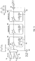
- Figure 13 is a schematic showing an electronic circuit that may be employed to process the radiation intensity signals that are generated by the detectors D na and D nr of the device.
- One problem with the output of the detectors of the device is that the background signal on which the absorption band signals are superposed can have a very large dynamic range that may be significantly greater than the differences between the absorption bands, and which varies rapidly with time. This has the result that, if a conventional circuit were used, an extremely high resolution analogue-to-digital converter would be required to cover the full dynamic range of the signals while being sensitive enough to measure small differences between the signals.
- the circuit that is employed according to this aspect has the advantage that lower cost components may be ued while having the required bandwidth do deal with changes in the signal intensities.
- the circuit comprises a pair of a pair of photodetectors 71 and 72 forming absorption detectors D na and reference detectors D nr respectively for detecting the absorption band attenuated radiation intensity and the reference radiation intensity for one absorption band. Additional circuits corresponding to the circuit shown in Figure 4 are required to detect the intensity of the other absorption bands.
- the detectors may be for example a pin photodiode or an avalanche photodiode as is conventional.
- the outputs from the photodetectors 70 and 72 are fed into preamplifiers 74 and 76 whose output is fed into time division mulitiplexer 78.
- the outputs I1 and I 2 of the preamplifiers 74 and 76 respectively are chopped alternately with the output of a high frequency oscillator 80 to give a square wave alternately proportional to I 2 and I 1 , and the output is fed into the input of a variable gain differential amplifier of a closed-loop gain block 84. Time-division multiplexing of the outputs I 1 and I 2 is performed so that the same gain can be applied both outputs by the differential amplifier 82.
- the output from gain block 84 is fed into a second gain block 86.
- gain blocks are employed, but more or fewer may be used as is necessary in order that the circuit is capable of handling the dynamic range of the variations in intensity of the detected radiation.
- the purpose of the gain blocks is to reduce the dynamic range of the signals to a manageable level while preserving the ratio information of I 1 and I 2 .
- an amplified version of the input formed by the amplifier 82 is demodulated with the oscillator signal by demodulator 90 to give just I 2 .
- the signal I 2 from the demultiplexer is filtered with respect to a reference signal 92 by means of an integrating amplifier 94.
- the signal is then demodulated by demodulator 96 using the anti-phase of the oscillator 80 formed by inverter 98 to remove I 2 and leave I 1 as the input to the amplifier.
- the required ratio I 1 / I 2 can be calculated in the digits from the output signal G T / I 1 .
- the output of the circuit is thus not dependent on the rapidly time-varying background signal, but only on the relatively slowly varying ratio I 1 / I 2 which has a much smaller dynamic range than the absolute value of the individual absorption bands.
Claims (15)
- Dispositif pour déterminer la composition d'un mélange de fluides qui s'écoulent le long d'un tuyau, qui comprend:- une source de radiation pour éclairer le mélange avec une radiation;- un détecteur pour détecter une radiation qui a été atténuée par le mélange;- un dispositif pour surveiller le débit de fluide le long du tuyau et émettre un signal indicatif du débit;caractérisé en ce qu'il inclut un dispositif pour régler l'intensité de radiation émise par la source de radiation en réponse au signal indicatif du débit de sorte que l'intensité de la source de radiation est réduite si le débit se réduit, de sorte que la source de radiation ne fonctionne jamais à une puissance supérieure au minimum requis pour éclairer le mélange avec ladite radiation à un débit donné.
- Dispositif selon la revendication 1, caractérisé en ce que ladite source de radiation est une source NIR à bande large synthétisée à partir de dispositifs à l'état solide.
- Dispositif tel que revendiqué dans l'une quelconque des revendications 1 ou 2, caractérisé en ce que la source de radiation est une source de radiation à bande large utilisable pour émettre une radiation sur toute la gamme de bandes d'absorption des fluides.
- Dispositif tel que revendiqué dans l'une quelconque des revendications 1 à 3, caractérisé en ce qu'il inclut un dispositif de miroir numérique pour moduler une radiation de la source de radiation.
- Dispositif selon l'une quelconque des revendications précédentes, caractérisé en ce que ladite source de radiation a une gamme de longueurs d'onde qui s'étend sur une bande d'absorption prédéfinie de chacun desdits fluides et sur au moins une bande de référence prédéfinie à l'extérieur de, mais adjacente à, chacune desdites bandes d'absorption, et en ce qu'il comprend un dispositif de séparation configuré pour séparer la radiation atténuée avant qu'elle n'atteigne ledit détecteur, où ledit dispositif de séparation comprend:- un premier diviseur de radiation configuré pour séparer ladite radiation atténuée (32) en faisceaux avec différentes bandes de longueur d'onde correspondantes, chacune desquelles s'étendant sur la bande d'absorption d'un fluide correspondant desdits fluides et sur au moins une desdites bandes de référence adjacentes à ladite bande d'absorption;- un deuxième diviseur de radiation (42) configuré pour recevoir dudit premier diviseur de radiation les faisceaux de radiation (33, 34, 36, 38, 40) correspondant à l'une desdites différentes bandes de longueur d'onde et pour séparer en outre chaque faisceau en faisceaux avec deux bandes de longueur d'onde correspondantes, l'une desquelles correspondant à la bande d'absorption respective et l'autre correspondant à au moins l'une des bandes de référence respective adjacentes à ladite bande d'absorption.
- Dispositif tel que revendiqué dans la revendication 5, caractérisé en ce que le dispositif pour séparer la radiation comprend un séparateur de faisceau dichroïque et/ou un filtre coupe-bande ondulé.
- Dispositif tel que revendiqué dans la revendication 6, caractérisé en ce que ledit premier diviseur de radiation inclut une pluralité de séparateurs de faisceau dichroïques (DBn) pour séparer la radiation en une pluralité de bandes de longueur d'onde, et ledit deuxième diviseur de radiation inclut un filtre coupe-bande ondulé (42) configuré pour séparer la radiation dans chaque bande de longueur d'onde en une bande d'absorption et une bande de référence ayant une gamme de longueur d'onde adjacente à la bande d'absorption.
- Dispositif tel que revendiqué dans la revendication 7, caractérisé en ce qu'il est disposé de sorte que la radiation frappe les séparateurs de faisceau dichroïques et/ou filtres coupe-bande ondulés à un angle d'incidence qui n'est pas supérieur à 20°.
- Dispositif tel que revendiqué dans l'une quelconque des revendications 5 à 8, caractérisé en ce qu'il est utilisable pour multiplexer une radiation d'une pluralité de sources de radiation à bande étroite pour générer la radiation, et le détecteur est utilisable pour démultiplexer la radiation détectée.
- Procédé de détermination de la composition d'un mélange de fluides qui s'écoulent le long d'un tuyau, comprenant les étapes de:- éclairer le mélange avec une radiation d'une source de radiation;- détecter une radiation qui a été atténuée par le mélange;- surveiller le débit du fluide le long du tuyau;caractérisé en ce qu'il inclut en outre l'étape de régler l'intensité de radiation émise par la source de radiation en réponse au débit déterminé de sorte que l'intensité de la source de radiation est réduite si le débit se réduit, de sorte que la source de radiation ne fonctionne jamais à une puissance supérieure au minimum requis pour éclairer le mélange avec ladite radiation à un débit donné.
- Procédé tel que revendiqué dans la revendication 10, caractérisé en ce que ladite radiation est émise à partir d'une source de radiation ayant une gamme de longueurs d'onde qui s'étend sur une bande d'absorption de chacun desdits fluides et sur au moins une bande de référence à l'extérieur de, mais adjacente à, chacune desdites bandes d'absorption, et en ce qu'il comprend en outre les étapes de:- séparer la radiation qui a été atténuée par le mélange en faisceaux avec différentes bandes de longueur d'onde correspondantes, chacune desquelles s'étend sur la bande d'absorption d'un fluide correspondant desdits fluides et sur au moins une desdites bandes de référence adjacente à ladite bande d'absorption;- recevoir les faisceaux de radiation séparée correspondant à chacune desdites différentes bandes de longueur d'onde, et séparer en outre chaque faisceau en faisceaux avec deux bandes de longueur d'onde, l'une desquelles correspondant à la bande d'absorption respective et l'autre correspondant à au moins l'une des bandes de référence respectives adjacentes à ladite bande d'absorption;- lesdites étapes de séparation étant effectuées avant ladite étape de détection.
- Procédé tel que revendiqué dans la revendication 11, caractérisé en ce que ladite étape de séparation comprend séparer la radiation atténuée en deux desdites bandes de référence situées adjacentes et sur des côtés opposés de la bande d'absorption de l'un des fluides.
- Procédé tel que revendiqué dans la revendication 12, caractérisé en ce que lesdites deux bandes de référence sont situées de manière sensiblement symétrique sur chaque côté de ladite bande d'absorption.
- Procédé tel que revendiqué dans l'une quelconque des revendications 12 ou 13, caractérisé en ce qu'il inclut l'étape d'interpoler le niveau d'absorption de la radiation dans lesdites deux bandes de référence de façon à générer une base de référence pour la bande d'absorption correspondante.
- Procédé tel que revendiqué dans l'une quelconque des revendications 10 à 14, caractérisé en ce que le mélange comprend de l'eau et des hydrocarbures.
Applications Claiming Priority (3)
| Application Number | Priority Date | Filing Date | Title |
|---|---|---|---|
| GB0909662A GB0909662D0 (en) | 2009-06-04 | 2009-06-04 | Device and method for determining the composition of a mixture of fluids |
| EP10730819.9A EP2438425B1 (fr) | 2009-06-04 | 2010-06-04 | Dispositif et procédé permettant de déterminer la composition d'un mélange de fluides |
| PCT/GB2010/001109 WO2010139965A2 (fr) | 2009-06-04 | 2010-06-04 | Dispositif et procédé permettant de déterminer la composition d'un mélange de fluides |
Related Parent Applications (2)
| Application Number | Title | Priority Date | Filing Date |
|---|---|---|---|
| EP10730819.9A Division EP2438425B1 (fr) | 2009-06-04 | 2010-06-04 | Dispositif et procédé permettant de déterminer la composition d'un mélange de fluides |
| EP10730819.9A Division-Into EP2438425B1 (fr) | 2009-06-04 | 2010-06-04 | Dispositif et procédé permettant de déterminer la composition d'un mélange de fluides |
Publications (3)
| Publication Number | Publication Date |
|---|---|
| EP2919006A2 EP2919006A2 (fr) | 2015-09-16 |
| EP2919006A3 EP2919006A3 (fr) | 2015-10-07 |
| EP2919006B1 true EP2919006B1 (fr) | 2021-05-19 |
Family
ID=40936935
Family Applications (2)
| Application Number | Title | Priority Date | Filing Date |
|---|---|---|---|
| EP10730819.9A Active EP2438425B1 (fr) | 2009-06-04 | 2010-06-04 | Dispositif et procédé permettant de déterminer la composition d'un mélange de fluides |
| EP15160926.0A Active EP2919006B1 (fr) | 2009-06-04 | 2010-06-04 | Dispositif et procédé permettant de déterminer la composition d'un mélange de fluides |
Family Applications Before (1)
| Application Number | Title | Priority Date | Filing Date |
|---|---|---|---|
| EP10730819.9A Active EP2438425B1 (fr) | 2009-06-04 | 2010-06-04 | Dispositif et procédé permettant de déterminer la composition d'un mélange de fluides |
Country Status (8)
| Country | Link |
|---|---|
| US (1) | US9933360B2 (fr) |
| EP (2) | EP2438425B1 (fr) |
| AU (1) | AU2010255551B2 (fr) |
| CA (2) | CA2764198C (fr) |
| GB (1) | GB0909662D0 (fr) |
| IN (1) | IN2015DN02309A (fr) |
| MX (1) | MX2011012992A (fr) |
| WO (1) | WO2010139965A2 (fr) |
Families Citing this family (16)
| Publication number | Priority date | Publication date | Assignee | Title |
|---|---|---|---|---|
| WO2011074193A1 (fr) * | 2009-12-15 | 2011-06-23 | パナソニック株式会社 | Dispositif de commande automatique de gain et appareil électronique |
| DE102012100794B3 (de) * | 2012-01-31 | 2013-02-28 | Airbus Operations Gmbh | Vorrichtung und Verfahren zum Erfassen von Kontaminationen in einem Hydrauliksystem |
| US20130314695A1 (en) * | 2012-05-24 | 2013-11-28 | Halliburton Energy Services, Inc. | Spectral Analysis Techniques Based Upon Spectral Monitoring of a Matrix |
| WO2014205240A1 (fr) * | 2013-06-19 | 2014-12-24 | Digi-Star, Llc | Dispositif portatif de détection d'humidité |
| DE112013007716T5 (de) | 2013-12-17 | 2016-09-15 | Aktiebolaget Skf | Optischer Fasersensor zur Ölzustandsüberwachung |
| GB2526784A (en) * | 2014-05-26 | 2015-12-09 | Skf Ab | Micro electro optical mechanical system |
| US10591639B2 (en) * | 2014-10-17 | 2020-03-17 | Halliburton Energy Services, Inc. | Methods and systems employing a flow prediction model based on acoustic activity and proppant compensation |
| JP6361461B2 (ja) * | 2014-10-21 | 2018-07-25 | 住友電気工業株式会社 | プローブ |
| AU2015408766A1 (en) | 2015-09-09 | 2018-02-01 | Halliburton Energy Services, Inc. | Methods and systems for optical links in downhole oil well operations |
| US10585210B2 (en) | 2015-10-06 | 2020-03-10 | Arable Labs, Inc. | Apparatus for radiometric correction and orthorectification of aerial imagery |
| US9995725B2 (en) | 2016-06-28 | 2018-06-12 | Schlumberger Technology Corporation | Phase fraction measurement using light source adjusted in discrete steps |
| US10054537B2 (en) * | 2016-06-28 | 2018-08-21 | Schlumberger Technology Corporation | Phase fraction measurement using continuously adjusted light source |
| US9939319B2 (en) | 2016-07-05 | 2018-04-10 | Arable Labs, Inc. | Radiation measuring systems and methods thereof |
| CN109959637B (zh) * | 2019-04-04 | 2021-06-01 | 中南大学 | 用于玻璃药瓶残氧量检测的标准具效应抑制方法及装置 |
| EP3889580A1 (fr) * | 2020-04-05 | 2021-10-06 | TGTW Group B.V. | Système et procédé de mesure de contaminants dans un matériau sensiblement translucide, tel que de l'eau |
| WO2022185311A1 (fr) * | 2021-03-04 | 2022-09-09 | Maytronics Ltd. | Systèmes et procédés pour la surveillance de fluide d'une installation de fluide ayant un sous-système d'inspection pour l'inspection de sources de lumière utilisées dans le système de surveillance |
Family Cites Families (19)
| Publication number | Priority date | Publication date | Assignee | Title |
|---|---|---|---|---|
| FR2170880B1 (fr) * | 1972-02-04 | 1976-06-11 | Souriau & Cie | |
| US3941487A (en) * | 1973-04-16 | 1976-03-02 | Beckman Instruments, Inc. | Colorimetric fluid analyzer |
| FI90592C (fi) * | 1989-02-16 | 1994-02-25 | Anadis Instr Sa | IR-spektrometrinen analysointimenetelmä sekä IR-spektrometri |
| US4914719A (en) * | 1989-03-10 | 1990-04-03 | Criticare Systems, Inc. | Multiple component gas analyzer |
| US4980554A (en) * | 1989-03-31 | 1990-12-25 | The United States Of America As Represented By The Secretary Of The Army | Laser line identifier |
| US5406082A (en) * | 1992-04-24 | 1995-04-11 | Thiokol Corporation | Surface inspection and characterization system and process |
| US5365067A (en) * | 1993-06-30 | 1994-11-15 | National Research Council Of Canada | Method and device for evaluation of surface properties, especially molecular orientation, in non-transparent layers |
| US5475221A (en) * | 1994-05-11 | 1995-12-12 | Brimrose Corporation Of America | Optical spectrometer using light emitting diode array |
| FI107194B (fi) * | 1996-03-14 | 2001-06-15 | Instrumentarium Oy | Kaasuseosten analysointi infrapunamenetelmällä |
| JPH10111236A (ja) * | 1996-10-03 | 1998-04-28 | Nippon Koden Corp | 炭酸ガス濃度測定装置 |
| US6292756B1 (en) | 1998-02-26 | 2001-09-18 | Premier Instruments, Inc. | Narrow band infrared water fraction apparatus for gas well and liquid hydrocarbon flow stream use |
| US6844554B2 (en) * | 2002-06-28 | 2005-01-18 | Instrumentarium Corp. | Method and arrangement for determining the concentration of a gas component in a gas mixture |
| US6972415B2 (en) * | 2002-09-26 | 2005-12-06 | R-Can Environmental Inc. | Fluid treatment system with UV sensor and intelligent driver |
| US7088456B2 (en) | 2004-04-24 | 2006-08-08 | Honeywell International Inc. | Thin film thickness measurement using multichannel infrared sensor |
| US7834312B2 (en) | 2005-02-24 | 2010-11-16 | Weatherford/Lamb, Inc. | Water detection and 3-phase fraction measurement systems |
| US7233001B2 (en) * | 2005-02-24 | 2007-06-19 | Weatherford/Lamb, Inc. | Multi-channel infrared optical phase fraction meter |
| GB2426579B (en) * | 2005-05-28 | 2008-01-16 | Schlumberger Holdings | Devices and methods for quantification of liquids in gas-condensate wells |
| DE102005025675A1 (de) | 2005-06-03 | 2006-11-16 | Siemens Ag | Strahleranordnung für einen nichtdispersiven Infrarot-Gasanalysator |
| US7279678B2 (en) * | 2005-08-15 | 2007-10-09 | Schlumber Technology Corporation | Method and apparatus for composition analysis in a logging environment |
-
2009
- 2009-06-04 GB GB0909662A patent/GB0909662D0/en not_active Ceased
-
2010
- 2010-06-04 CA CA2764198A patent/CA2764198C/fr active Active
- 2010-06-04 IN IN2309DEN2015 patent/IN2015DN02309A/en unknown
- 2010-06-04 EP EP10730819.9A patent/EP2438425B1/fr active Active
- 2010-06-04 AU AU2010255551A patent/AU2010255551B2/en not_active Ceased
- 2010-06-04 MX MX2011012992A patent/MX2011012992A/es active IP Right Grant
- 2010-06-04 US US13/322,439 patent/US9933360B2/en active Active
- 2010-06-04 WO PCT/GB2010/001109 patent/WO2010139965A2/fr active Application Filing
- 2010-06-04 CA CA2894104A patent/CA2894104C/fr active Active
- 2010-06-04 EP EP15160926.0A patent/EP2919006B1/fr active Active
Also Published As
| Publication number | Publication date |
|---|---|
| GB0909662D0 (en) | 2009-07-22 |
| US20120112072A1 (en) | 2012-05-10 |
| EP2919006A2 (fr) | 2015-09-16 |
| EP2438425B1 (fr) | 2015-08-12 |
| EP2919006A3 (fr) | 2015-10-07 |
| IN2015DN02309A (fr) | 2015-08-28 |
| WO2010139965A2 (fr) | 2010-12-09 |
| EP2438425A2 (fr) | 2012-04-11 |
| CA2894104A1 (fr) | 2010-12-09 |
| CA2764198A1 (fr) | 2010-12-09 |
| WO2010139965A3 (fr) | 2011-03-10 |
| MX2011012992A (es) | 2012-03-06 |
| US9933360B2 (en) | 2018-04-03 |
| AU2010255551A1 (en) | 2012-01-12 |
| CA2764198C (fr) | 2016-08-16 |
| CA2894104C (fr) | 2018-06-19 |
| AU2010255551B2 (en) | 2013-04-18 |
Similar Documents
| Publication | Publication Date | Title |
|---|---|---|
| EP2919006B1 (fr) | Dispositif et procédé permettant de déterminer la composition d'un mélange de fluides | |
| EP2758766B1 (fr) | Capteur infrarouge multisources pour mesure des gaz | |
| US9939374B2 (en) | Device and method for fast recording of an absorption spectrum of a fluid using a plurality of etalons in combination with a tunable fabry-perot interferometer | |
| US7570360B1 (en) | Optical absorption spectrometer and method for measuring concentration of a substance | |
| JPH09325116A (ja) | 測定装置 | |
| WO2018009953A1 (fr) | Appareil et procédé d'interférométrie photothermique | |
| JPWO2003073127A1 (ja) | 気象観測ライダーシステム | |
| CA3025276C (fr) | Dispositif de mesure et procede pour detecter differents gaz et differentes concentrations gazeuses | |
| JP2010539464A (ja) | 分光偏光ハイパースペクトル撮像装置 | |
| WO2005047834A1 (fr) | Processeur de lumiere assurant un controle de longueurs d'onde et procede associe | |
| KR101103091B1 (ko) | 파장 라우터를 이용한 전자기 스펙트럼으로부터의 시료의측정 | |
| US11162893B2 (en) | Device and method for determining the composition of a mixture of fluids | |
| JP6059484B2 (ja) | 流動性媒体中の物質濃度の高分解能測定装置 | |
| RU2478192C2 (ru) | Способ оптического дистанционного обнаружения соединений в среде | |
| US10241044B2 (en) | NDIR glucose detection in liquids | |
| US6614527B2 (en) | Spectral bandwidth calibration of an optical spectrum analyzer | |
| EP3030884A1 (fr) | Dispositif informatique optique et procédé de compensation des fluctuations de lumière | |
| Rhoades et al. | The AC-Spectra, an instrument for hyperspectral characterization of inherent optical properties in natural waters | |
| CN114144655A (zh) | 用于确定物质浓度的测量装置和方法 | |
| Johansen et al. | Infrared detection of carbon monoxide with a micromechanically tunable silicon fabry-perot filter | |
| US20130194576A1 (en) | Optical probe for measuring absorption at a plurality of wavelengths | |
| JP2023533541A (ja) | レーザヘテロダイン燃焼効率モニタ及び関連する方法 |
Legal Events
| Date | Code | Title | Description |
|---|---|---|---|
| PUAL | Search report despatched |
Free format text: ORIGINAL CODE: 0009013 |
|
| PUAI | Public reference made under article 153(3) epc to a published international application that has entered the european phase |
Free format text: ORIGINAL CODE: 0009012 |
|
| AC | Divisional application: reference to earlier application |
Ref document number: 2438425 Country of ref document: EP Kind code of ref document: P |
|
| AK | Designated contracting states |
Kind code of ref document: A2 Designated state(s): AL AT BE BG CH CY CZ DE DK EE ES FI FR GB GR HR HU IE IS IT LI LT LU LV MC MK MT NL NO PL PT RO SE SI SK SM TR |
|
| AK | Designated contracting states |
Kind code of ref document: A3 Designated state(s): AL AT BE BG CH CY CZ DE DK EE ES FI FR GB GR HR HU IE IS IT LI LT LU LV MC MK MT NL NO PL PT RO SE SI SK SM TR |
|
| RIC1 | Information provided on ipc code assigned before grant |
Ipc: G01N 21/359 20140101ALI20150902BHEP Ipc: G01N 33/28 20060101AFI20150902BHEP Ipc: G01N 21/3577 20140101ALI20150902BHEP Ipc: G01N 21/31 20060101ALN20150902BHEP |
|
| 17P | Request for examination filed |
Effective date: 20160406 |
|
| RBV | Designated contracting states (corrected) |
Designated state(s): AL AT BE BG CH CY CZ DE DK EE ES FI FR GB GR HR HU IE IS IT LI LT LU LV MC MK MT NL NO PL PT RO SE SI SK SM TR |
|
| STAA | Information on the status of an ep patent application or granted ep patent |
Free format text: STATUS: EXAMINATION IS IN PROGRESS |
|
| 17Q | First examination report despatched |
Effective date: 20170711 |
|
| GRAP | Despatch of communication of intention to grant a patent |
Free format text: ORIGINAL CODE: EPIDOSNIGR1 |
|
| STAA | Information on the status of an ep patent application or granted ep patent |
Free format text: STATUS: GRANT OF PATENT IS INTENDED |
|
| RIC1 | Information provided on ipc code assigned before grant |
Ipc: G01N 21/31 20060101ALN20210114BHEP Ipc: G01N 21/3577 20140101ALI20210114BHEP Ipc: G01N 33/28 20060101AFI20210114BHEP Ipc: G01N 21/359 20140101ALI20210114BHEP |
|
| INTG | Intention to grant announced |
Effective date: 20210127 |
|
| RIC1 | Information provided on ipc code assigned before grant |
Ipc: G01N 21/3577 20140101ALI20210115BHEP Ipc: G01N 33/28 20060101AFI20210115BHEP Ipc: G01N 21/359 20140101ALI20210115BHEP Ipc: G01N 21/31 20060101ALN20210115BHEP |
|
| GRAS | Grant fee paid |
Free format text: ORIGINAL CODE: EPIDOSNIGR3 |
|
| GRAA | (expected) grant |
Free format text: ORIGINAL CODE: 0009210 |
|
| STAA | Information on the status of an ep patent application or granted ep patent |
Free format text: STATUS: THE PATENT HAS BEEN GRANTED |
|
| AC | Divisional application: reference to earlier application |
Ref document number: 2438425 Country of ref document: EP Kind code of ref document: P |
|
| AK | Designated contracting states |
Kind code of ref document: B1 Designated state(s): AL AT BE BG CH CY CZ DE DK EE ES FI FR GB GR HR HU IE IS IT LI LT LU LV MC MK MT NL NO PL PT RO SE SI SK SM TR |
|
| REG | Reference to a national code |
Ref country code: GB Ref legal event code: FG4D |
|
| REG | Reference to a national code |
Ref country code: CH Ref legal event code: EP |
|
| REG | Reference to a national code |
Ref country code: DE Ref legal event code: R096 Ref document number: 602010067020 Country of ref document: DE |
|
| REG | Reference to a national code |
Ref country code: AT Ref legal event code: REF Ref document number: 1394486 Country of ref document: AT Kind code of ref document: T Effective date: 20210615 |
|
| REG | Reference to a national code |
Ref country code: IE Ref legal event code: FG4D |
|
| REG | Reference to a national code |
Ref country code: LT Ref legal event code: MG9D |
|
| REG | Reference to a national code |
Ref country code: AT Ref legal event code: MK05 Ref document number: 1394486 Country of ref document: AT Kind code of ref document: T Effective date: 20210519 |
|
| REG | Reference to a national code |
Ref country code: NL Ref legal event code: MP Effective date: 20210519 |
|
| PG25 | Lapsed in a contracting state [announced via postgrant information from national office to epo] |
Ref country code: HR Free format text: LAPSE BECAUSE OF FAILURE TO SUBMIT A TRANSLATION OF THE DESCRIPTION OR TO PAY THE FEE WITHIN THE PRESCRIBED TIME-LIMIT Effective date: 20210519 Ref country code: BG Free format text: LAPSE BECAUSE OF FAILURE TO SUBMIT A TRANSLATION OF THE DESCRIPTION OR TO PAY THE FEE WITHIN THE PRESCRIBED TIME-LIMIT Effective date: 20210819 Ref country code: AT Free format text: LAPSE BECAUSE OF FAILURE TO SUBMIT A TRANSLATION OF THE DESCRIPTION OR TO PAY THE FEE WITHIN THE PRESCRIBED TIME-LIMIT Effective date: 20210519 Ref country code: FI Free format text: LAPSE BECAUSE OF FAILURE TO SUBMIT A TRANSLATION OF THE DESCRIPTION OR TO PAY THE FEE WITHIN THE PRESCRIBED TIME-LIMIT Effective date: 20210519 Ref country code: LT Free format text: LAPSE BECAUSE OF FAILURE TO SUBMIT A TRANSLATION OF THE DESCRIPTION OR TO PAY THE FEE WITHIN THE PRESCRIBED TIME-LIMIT Effective date: 20210519 |
|
| PG25 | Lapsed in a contracting state [announced via postgrant information from national office to epo] |
Ref country code: LV Free format text: LAPSE BECAUSE OF FAILURE TO SUBMIT A TRANSLATION OF THE DESCRIPTION OR TO PAY THE FEE WITHIN THE PRESCRIBED TIME-LIMIT Effective date: 20210519 Ref country code: IS Free format text: LAPSE BECAUSE OF FAILURE TO SUBMIT A TRANSLATION OF THE DESCRIPTION OR TO PAY THE FEE WITHIN THE PRESCRIBED TIME-LIMIT Effective date: 20210919 Ref country code: GR Free format text: LAPSE BECAUSE OF FAILURE TO SUBMIT A TRANSLATION OF THE DESCRIPTION OR TO PAY THE FEE WITHIN THE PRESCRIBED TIME-LIMIT Effective date: 20210820 Ref country code: PT Free format text: LAPSE BECAUSE OF FAILURE TO SUBMIT A TRANSLATION OF THE DESCRIPTION OR TO PAY THE FEE WITHIN THE PRESCRIBED TIME-LIMIT Effective date: 20210920 Ref country code: NO Free format text: LAPSE BECAUSE OF FAILURE TO SUBMIT A TRANSLATION OF THE DESCRIPTION OR TO PAY THE FEE WITHIN THE PRESCRIBED TIME-LIMIT Effective date: 20210819 Ref country code: PL Free format text: LAPSE BECAUSE OF FAILURE TO SUBMIT A TRANSLATION OF THE DESCRIPTION OR TO PAY THE FEE WITHIN THE PRESCRIBED TIME-LIMIT Effective date: 20210519 Ref country code: ES Free format text: LAPSE BECAUSE OF FAILURE TO SUBMIT A TRANSLATION OF THE DESCRIPTION OR TO PAY THE FEE WITHIN THE PRESCRIBED TIME-LIMIT Effective date: 20210519 Ref country code: SE Free format text: LAPSE BECAUSE OF FAILURE TO SUBMIT A TRANSLATION OF THE DESCRIPTION OR TO PAY THE FEE WITHIN THE PRESCRIBED TIME-LIMIT Effective date: 20210519 |
|
| REG | Reference to a national code |
Ref country code: NO Ref legal event code: MMEP |
|
| REG | Reference to a national code |
Ref country code: NO Ref legal event code: T2 |
|
| PG25 | Lapsed in a contracting state [announced via postgrant information from national office to epo] |
Ref country code: NL Free format text: LAPSE BECAUSE OF FAILURE TO SUBMIT A TRANSLATION OF THE DESCRIPTION OR TO PAY THE FEE WITHIN THE PRESCRIBED TIME-LIMIT Effective date: 20210519 |
|
| REG | Reference to a national code |
Ref country code: DE Ref legal event code: R119 Ref document number: 602010067020 Country of ref document: DE |
|
| PG25 | Lapsed in a contracting state [announced via postgrant information from national office to epo] |
Ref country code: RO Free format text: LAPSE BECAUSE OF FAILURE TO SUBMIT A TRANSLATION OF THE DESCRIPTION OR TO PAY THE FEE WITHIN THE PRESCRIBED TIME-LIMIT Effective date: 20210519 Ref country code: NO Free format text: LAPSE BECAUSE OF FAILURE TO SUBMIT A TRANSLATION OF THE DESCRIPTION OR TO PAY THE FEE WITHIN THE PRESCRIBED TIME-LIMIT Effective date: 20210819 Ref country code: DK Free format text: LAPSE BECAUSE OF FAILURE TO SUBMIT A TRANSLATION OF THE DESCRIPTION OR TO PAY THE FEE WITHIN THE PRESCRIBED TIME-LIMIT Effective date: 20210519 Ref country code: EE Free format text: LAPSE BECAUSE OF FAILURE TO SUBMIT A TRANSLATION OF THE DESCRIPTION OR TO PAY THE FEE WITHIN THE PRESCRIBED TIME-LIMIT Effective date: 20210519 Ref country code: CZ Free format text: LAPSE BECAUSE OF FAILURE TO SUBMIT A TRANSLATION OF THE DESCRIPTION OR TO PAY THE FEE WITHIN THE PRESCRIBED TIME-LIMIT Effective date: 20210519 Ref country code: SM Free format text: LAPSE BECAUSE OF FAILURE TO SUBMIT A TRANSLATION OF THE DESCRIPTION OR TO PAY THE FEE WITHIN THE PRESCRIBED TIME-LIMIT Effective date: 20210519 Ref country code: SK Free format text: LAPSE BECAUSE OF FAILURE TO SUBMIT A TRANSLATION OF THE DESCRIPTION OR TO PAY THE FEE WITHIN THE PRESCRIBED TIME-LIMIT Effective date: 20210519 |
|
| PGRI | Patent reinstated in contracting state [announced from national office to epo] |
Ref country code: NO Effective date: 20211119 |
|
| REG | Reference to a national code |
Ref country code: CH Ref legal event code: PL |
|
| REG | Reference to a national code |
Ref country code: NO Ref legal event code: T2 Effective date: 20210519 |
|
| REG | Reference to a national code |
Ref country code: BE Ref legal event code: MM Effective date: 20210630 |
|
| PLBE | No opposition filed within time limit |
Free format text: ORIGINAL CODE: 0009261 |
|
| STAA | Information on the status of an ep patent application or granted ep patent |
Free format text: STATUS: NO OPPOSITION FILED WITHIN TIME LIMIT |
|
| PG25 | Lapsed in a contracting state [announced via postgrant information from national office to epo] |
Ref country code: MC Free format text: LAPSE BECAUSE OF FAILURE TO SUBMIT A TRANSLATION OF THE DESCRIPTION OR TO PAY THE FEE WITHIN THE PRESCRIBED TIME-LIMIT Effective date: 20210519 Ref country code: LU Free format text: LAPSE BECAUSE OF NON-PAYMENT OF DUE FEES Effective date: 20210604 |
|
| 26N | No opposition filed |
Effective date: 20220222 |
|
| PG25 | Lapsed in a contracting state [announced via postgrant information from national office to epo] |
Ref country code: LI Free format text: LAPSE BECAUSE OF NON-PAYMENT OF DUE FEES Effective date: 20210630 Ref country code: IE Free format text: LAPSE BECAUSE OF NON-PAYMENT OF DUE FEES Effective date: 20210604 Ref country code: DE Free format text: LAPSE BECAUSE OF NON-PAYMENT OF DUE FEES Effective date: 20220101 Ref country code: CH Free format text: LAPSE BECAUSE OF NON-PAYMENT OF DUE FEES Effective date: 20210630 |
|
| PG25 | Lapsed in a contracting state [announced via postgrant information from national office to epo] |
Ref country code: IS Free format text: LAPSE BECAUSE OF FAILURE TO SUBMIT A TRANSLATION OF THE DESCRIPTION OR TO PAY THE FEE WITHIN THE PRESCRIBED TIME-LIMIT Effective date: 20210919 Ref country code: FR Free format text: LAPSE BECAUSE OF NON-PAYMENT OF DUE FEES Effective date: 20210719 Ref country code: AL Free format text: LAPSE BECAUSE OF FAILURE TO SUBMIT A TRANSLATION OF THE DESCRIPTION OR TO PAY THE FEE WITHIN THE PRESCRIBED TIME-LIMIT Effective date: 20210519 |
|
| PG25 | Lapsed in a contracting state [announced via postgrant information from national office to epo] |
Ref country code: BE Free format text: LAPSE BECAUSE OF NON-PAYMENT OF DUE FEES Effective date: 20210630 |
|
| PGFP | Annual fee paid to national office [announced via postgrant information from national office to epo] |
Ref country code: NO Payment date: 20220622 Year of fee payment: 13 Ref country code: IT Payment date: 20220505 Year of fee payment: 13 Ref country code: GB Payment date: 20220627 Year of fee payment: 13 |
|
| PG25 | Lapsed in a contracting state [announced via postgrant information from national office to epo] |
Ref country code: HU Free format text: LAPSE BECAUSE OF FAILURE TO SUBMIT A TRANSLATION OF THE DESCRIPTION OR TO PAY THE FEE WITHIN THE PRESCRIBED TIME-LIMIT; INVALID AB INITIO Effective date: 20100604 Ref country code: CY Free format text: LAPSE BECAUSE OF FAILURE TO SUBMIT A TRANSLATION OF THE DESCRIPTION OR TO PAY THE FEE WITHIN THE PRESCRIBED TIME-LIMIT Effective date: 20210519 |
|
| REG | Reference to a national code |
Ref country code: NO Ref legal event code: MMEP |
|
| GBPC | Gb: european patent ceased through non-payment of renewal fee |
Effective date: 20230604 |
|
| PG25 | Lapsed in a contracting state [announced via postgrant information from national office to epo] |
Ref country code: MK Free format text: LAPSE BECAUSE OF FAILURE TO SUBMIT A TRANSLATION OF THE DESCRIPTION OR TO PAY THE FEE WITHIN THE PRESCRIBED TIME-LIMIT Effective date: 20210519 Ref country code: GB Free format text: LAPSE BECAUSE OF NON-PAYMENT OF DUE FEES Effective date: 20230604 |