EP2918986A1 - Vorrichtung zur Bestimmung des Drucks in einem Vakuumraum - Google Patents
Vorrichtung zur Bestimmung des Drucks in einem Vakuumraum Download PDFInfo
- Publication number
- EP2918986A1 EP2918986A1 EP14305338.7A EP14305338A EP2918986A1 EP 2918986 A1 EP2918986 A1 EP 2918986A1 EP 14305338 A EP14305338 A EP 14305338A EP 2918986 A1 EP2918986 A1 EP 2918986A1
- Authority
- EP
- European Patent Office
- Prior art keywords
- vacuum
- vacuum chamber
- meßstutzen
- metal tube
- tight
- Prior art date
- Legal status (The legal status is an assumption and is not a legal conclusion. Google has not performed a legal analysis and makes no representation as to the accuracy of the status listed.)
- Granted
Links
Images

Classifications
-
- G—PHYSICS
- G01—MEASURING; TESTING
- G01L—MEASURING FORCE, STRESS, TORQUE, WORK, MECHANICAL POWER, MECHANICAL EFFICIENCY, OR FLUID PRESSURE
- G01L21/00—Vacuum gauges
- G01L21/16—Vacuum gauges by measuring variation of frictional resistance of gases
- G01L21/24—Vacuum gauges by measuring variation of frictional resistance of gases using rotating members; Vacuum gauges of the Langmuir type
-
- G—PHYSICS
- G01—MEASURING; TESTING
- G01L—MEASURING FORCE, STRESS, TORQUE, WORK, MECHANICAL POWER, MECHANICAL EFFICIENCY, OR FLUID PRESSURE
- G01L19/00—Details of, or accessories for, apparatus for measuring steady or quasi-steady pressure of a fluent medium insofar as such details or accessories are not special to particular types of pressure gauges
- G01L19/0007—Fluidic connecting means
- G01L19/0023—Fluidic connecting means for flowthrough systems having a flexible pressure transmitting element
Definitions
- the invention relates to a device for determining the pressure in an evacuated vacuum chamber, which comprises an outwardly projecting and vacuum-tight connected to the vacuum chamber evacuated Meßstutzen.
- the Meßstutzen contains a gas friction sensor, which is arranged without contact by a generated by a patch in the working position on the Meßstutzen measuring head and set in rotation.
- a vacuum chamber i. a hermetically sealed, evacuated space may be, for example, the thermal insulation of a vacuum-insulated liquefied gas tank or the thermal insulation of a vacuum-insulated piping for guiding a cooled medium, for example helium or nitrogen, or the vacuum insulation of a cryogenic jacket of a superconducting cable.
- Vacuum chambers are also known as process chambers, for example in the semiconductor industry or the plasma coating. The following remarks relate to a vacuum insulation representative of all other possible vacuum chambers.
- Gas friction vacuum gauges also called ball friction gauges, for the determination of the gas pressure in the high vacuum range are known. They allow the measurement of the pressure to about 10 -5 Pa.
- a metal ball is mounted as a gas friction sensor by a magnet arrangement magnetically contactless and offset by a coil assembly about a stationary axis of rotation. After switching off the coil drive, the rotational frequency of the ball by the gas friction, ie by the impact of Gas molecules on the ball, down. From this, the pressure of the existing gas in the vacuum chamber can be calculated and displayed.
- the magnet and coil assembly which supports and drives the ball without contact, is aligned so that the gas friction sensor rotates in the measuring chamber about a vertical axis of rotation and the axis of symmetry of the magnet and coil assembly coincides with the axis of rotation.
- the metal tube must be aligned exactly horizontal, with tolerable deviations of its axis from the horizontal of about ⁇ 2 °. This spatial arrangement is necessary to avoid inaccuracies in the measurement of the vacuum.
- a tilting of the axis of rotation and thus the axis of the metal tube causes a deflection of the ball from the symmetry axis of the magnet and coil assembly due to gravity. By thus acting on the sphere changed magnetic fields it comes to faulty Gastikmeßhong. Also, in extreme deviations of the metal tube from the horizontal deflection, a measurement may not be possible.
- Fig. 1 illustrates a conduit 1 and its tail with a vacuum chamber 2 in cross section.
- a measuring head (not shown) is placed on the measuring nozzle 3, which contains the mentioned magnet and coil assembly.
- the Meßstutzen 3 must therefore be aligned horizontally accordingly.
- the tolerable deviation ⁇ of the axis A of the Meßstutzens 3 is also shown. The alignment or its correction is not always possible during or after retraction of the vacuum-insulated line 1.
- the measuring nozzle 3 is after retraction of the line 1 in one of the positions 3a or 3b, in which an error-free vacuum measurement by the deviating from the horizontal orientation of the Meßstutzens 3 is impossible.
- the rigidly projecting from the vacuum chamber 2 Meßstutzen 3 disturb during the retraction of the line 1 or even damaged.
- the above Meßstutzen 3 is susceptible to damage both in pipes and in tanks and other vacuum chambers.
- the invention has for its object to provide a device for the correct measurement of a vacuum with a gas friction vacuum in a spatially arbitrarily oriented vacuum chamber.
- a bendable metal tube is arranged, which is vacuum-tightly connected at one end to the Meßstutzen and with the other end vacuum-tight with the vacuum chamber.
- the device of the invention allows the measurement of the size of the vacuum, ie the pressure, regardless of the orientation of the vacuum chamber and regardless of where the junction of the flexible metal tube is located on the vacuum chamber. In working position, if a vacuum measurement is to be carried out, the measuring nozzle can therefore always be aligned horizontally. This ensures error-free measurement of the vacuum in the vacuum chamber.
- the flexible metal tube together with the Meßstutzen can be stored close to the vacuum chamber fitting, so that the Meßstutzen during installation of the vacuum chamber, for example, when pulling a vacuum insulated line, does not bother or not damaged.
- the device according to the invention can be used with all possible vacuum chambers. Furthermore, the device is very easy to manufacture and can be installed in principle on existing vacuum chambers, since they do not require redesign of the vacuum chamber itself.
- Fig. 2 is shown schematically in cross section a vacuum chamber 20 of a conduit 10 which is equipped with a device 40 according to the invention.
- the conduit 10 may be, for example, a liquefied gas line or a cryogenic jacket of a superconducting cable.
- the vacuum chamber 20 is formed of the hermetically sealed and evacuated space between two concentrically arranged metal tubes 21, 22.
- the two metal tubes 21, 22 may for example consist of stainless steel. They can be held in their mutual position by plastic spacers (not shown).
- the device 40 for determining the size of the vacuum, ie the pressure, in the vacuum chamber 20 comprises a measuring nozzle 30, which contains a gas friction sensor (not shown).
- the evacuated Meßstutzen 30 is hermetically sealed with the vacuum chamber 20th connected and also contains the vacuum to be measured.
- the hermetically sealed connection between measuring nozzle 30 and vacuum chamber 20 is made by a bendable metal tube 41 which is arranged between the vacuum chamber 20 and the measuring nozzle 30 and at one end vacuum-tight with the Meßstutzen 30 and with the other end vacuum-tight connected to the vacuum chamber 20.
- the bendable tube 41 is preferably a metal tube provided in a known manner with a helical or parallel corrugation.
- the bendable metal tube 41 may be made of, for example, stainless steel, aluminum, copper, a nickel alloy, or other suitable metal. For example, it has a diameter of 5 - 12 mm and is 5 - 50 cm long for frequently occurring dimensions of vacuum insulated pipelines.
- the bendable metal tube 41 is preferably connected by welding to the measuring stub 30 and the vacuum chamber 20.
- the gas friction sensor is arranged in contactless manner by means of a magnetic field generated by a measuring head (not shown) placed in the working position on the measuring stub 30 and can be set in rotation.
- the gas friction sensor is preferably a ball, for example made of stainless steel.
- the device 40 according to the invention can be stored in the rest position on the vacuum chamber.
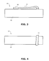
- Fig. 3 is the bendable metal tube 41 including the Meßstutzens 30 along the line 10 (or along the tail) parallel to this and adjacent to this stored.
- Fig. 4 the bendable metal tube 41 is mounted around the circumference of the conduit 10 (or its tail) adjacent thereto (the metering nozzle is not shown).
- An additional device for attachment and protection of the Meßstutzens 30 in the rest position is advantageously mounted in conjunction with the Meßstutzen 30.
- the vacuum chamber 20 on its outer side a suitable recess (not shown), which is designed so that the Meßstutzen 30 can be stored in the rest position in this.
- the measuring nozzle 30, for example, when retracting the line 10, does not stand out, and damage thereof can be avoided.
- the measuring nozzle 30 may also be covered in the rest position by a protective cover attached to the vacuum chamber 20.
Landscapes
- Physics & Mathematics (AREA)
- General Physics & Mathematics (AREA)
- Measuring Fluid Pressure (AREA)
- Containers, Films, And Cooling For Superconductive Devices (AREA)
Abstract
Description
- Die Erfindung bezieht sich auf eine Vorrichtung zur Bestimmung des Drucks in einer evakuierten Vakuumkammer, welche einen nach außen abstehenden und vakuumdicht mit der Vakuumkammer verbundenen evakuierten Meßstutzen umfaßt. Der Meßstutzen enthält einen Gasreibungssensor, welcher durch ein von einem in Arbeitsposition auf dem Meßstutzen aufgesetzten Meßkopf erzeugtes Magnetfeld berührungslos angeordnet und in Rotation versetzbar ist.
- Eine Vakuumkammer, d.h. ein hermetisch abgedichteter, evakuierter Raum, kann beispielsweise die thermische Isolierung eines vakuumisolierten Flüssiggastanks oder die thermische Isolierung einer vakuumisolierten Rohrleitung zur Führung eines gekühlten Mediums, beispielsweise Helium oder Stickstoff, oder die Vakuumisolierung einer kryogenen Ummantelung eines supraleitenden Kabels sein. Vakuumkammern sind weiterhin als Prozeßkammern, beispielsweise in der Halbleiterindustrie oder der Plasmabeschichtung, bekannt. Die folgenden Ausführungen beziehen sich auf eine Vakuumisolierung stellvertretend für alle anderen möglichen Vakuumkammern.
- Gasreibungsvakuummeßgeräte, auch Kugelreibungsvakuummeter genannt, für die Bestimmung des Gasdrucks im Hochvakuumbereich sind bekannt. Sie erlauben die Messung des Drucks bis ca. 10-5 Pa. In einer Meßkammer, die aus einem horizontal angeordneten Metallrohr bzw. Meßstutzen besteht und räumlich mit einer das zu messende Vakuum enthaltenden Vakuumkammer verbunden ist, wird eine Metallkugel als Gasreibungssensor durch eine Magnetanordnung magnetisch berührungslos gelagert und durch eine Spulenanordnung um eine ortsfeste Rotationsachse in Rotation versetzt. Nach dem Abschalten des Spulenantriebs nimmt die Drehfrequenz der Kugel durch die Gasreibung, d.h. durch den Aufprall von Gasmolekülen auf die Kugel, ab. Daraus läßt sich der Druck des vorhandenen Gases in der Vakuumkammer berechnen und anzeigen.
- Die Magnet- und Spulenanordnung, welche die Kugel berührungslos lagert und antreibt, wird so ausgerichtet, daß der Gasreibungssensor in der Meßkammer um eine vertikale Rotationsachse rotiert und die Symmetrieachse der Magnet- und Spulenanordnung mit der Rotationsachse übereinstimmt. Dafür muß das Metallrohr exakt horizontal ausgerichtet sein, mit tolerierbaren Abweichungen seiner Achse von der Horizontalen von ca. ± 2°. Diese räumliche Anordnung ist erforderlich, um Ungenauigkeiten bei der Messung des Vakuums zu vermeiden. Ein Verkippen der Rotationsachse und damit der Achse des Metallrohrs bewirkt aufgrund der Schwerkraft eine Auslenkung der Kugel aus der Symmetrieachse der Magnet- und Spulenanordnung. Durch die damit an der Kugel wirkenden veränderten Magnetfelder kommt es zu fehlerhaften Gasdruckmeßwerten. Auch ist bei extremen Abweichungen des Metallrohrs von der horizontalen Auslenkung eine Messung gegebenenfalls nicht möglich.
- Der Einsatz eines Gasreibungsvakuummeters ist daher insofern störanfällig, als daß das Metallrohr des Meßgeräts, in dem sich der Gasreibungssensor befindet, genau horizontal ausgerichtet werden muß. Dies ist insbesondere in Vakuumanlagen mit dauerhaft angebrachten Meßstutzen für den Anschluß eines Vakuummeters problematisch.
- Beispielsweise verfügen vakuumisolierte Leitungen für flüssigen Stickstoff oder vakuumisolierte Ummantelungen für supraleitende Kabel über Endstücke, die unter anderem solche angeschweißten Meßstutzen bzw. Meßkammern aufweisen.
Fig. 1 illustriert eine Leitung 1 bzw. deren Endstück mit einer Vakuumkammer 2 im Querschnitt. Zur Vakuummessung wird auf den Meßstutzen 3 ein Meßkopf (nicht dargestellt) aufgesetzt, der die erwähnte Magnet- und Spulenanordnung enthält. Der Meßstutzen 3 muß deshalb entsprechend horizontal ausgerichtet sein. Die tolerierbare Abweichung α der Achse A des Meßstutzens 3 ist ebenfalls dargestellt. Die Ausrichtung bzw. deren Korrektur ist während bzw. nach dem Einziehen der vakuumisolierten Leitung 1 nicht immer möglich. So kann es beispielsweise vorkommen, daß sich der Meßstutzen 3 nach dem Einziehen der Leitung 1 in einer der Positionen 3a oder 3b befindet, in welchen eine fehlerfreie Vakuummessung durch die von der Horizontalen abweichende Ausrichtung des Meßstutzens 3 unmöglich ist. Des weiteren kann der starr von der Vakuumkammer 2 abstehende Meßstutzen 3 während des Einziehens der Leitung 1 stören oder auch beschädigt werden. Auch ist der vorstehende Meßstutzen 3 sowohl bei Leitungen als auch bei Tanks und anderen Vakuumkammern beschädigungsanfällig. - Der Erfindung liegt die Aufgabe zugrunde, eine Vorrichtung zur korrekten Messung eines Vakuums mit einem Gasreibungsvakuummeßgerät in einer räumlich beliebig orientierten Vakuumkammer bereitzustellen.
- Diese Aufgabe wird gemäß der Erfindung dadurch gelöst, daß zwischen der Vakuumkammer und dem Meßstutzen ein biegbares Metallrohr angeordnet ist, das mit einem Ende vakuumdicht mit dem Meßstutzen und mit dem anderen Ende vakuumdicht mit der Vakuumkammer verbunden ist.
- Die erfindungsgemäße Vorrichtung erlaubt die Messung der Größe des Vakuums, d.h. des Drucks, unabhängig von der Orientierung der Vakuumkammer und unabhängig davon, wo die Anschlußstelle des biegsamen Metallrohrs an der Vakuumkammer liegt. In Arbeitsstellung, wenn eine Vakuummessung durchgeführt werden soll, kann der Meßstutzen deshalb stets horizontal ausgerichtet werden. Dadurch ist eine fehlerfreie Messung des Vakuums in der Vakuumkammer gewährleistet. In Ruhestellung, wenn der Meßstutzen nicht benötigt wird, kann das biegsame Metallrohr samt dem Meßstutzen dicht an der Vakuumkammer anliegend gelagert werden, sodaß der Meßstutzen bei der Installation der Vakuumkammer, beispielsweise beim Einziehen einer vakuum isolierten Leitung, nicht stört bzw. nicht beschädigt wird. Von besonderem Vorteil ist, daß sich die erfindungsgemäße Vorrichtung mit allen möglichen Vakuumkammern zur Anwendung bringen läßt. Weiterhin ist die Vorrichtung sehr einfach herstellbar und läßt sich prinzipiell auch an bereits bestehenden Vakuumkammern installieren, da sie keine Umgestaltung der Vakuumkammer selbst erfordert.
- Ausführungsbeispiele des Erfindungsgegenstandes sind in den Zeichnungen dargestellt. Es zeigen:
-
Fig. 1 , bereits oben beschrieben, schematisch einen Querschnitt einer vakuum isolierten Leitung mit einem Meßstutzen zur Bestimmung des Vakuums in der Vakuumkammer, -
Fig. 2 schematisch einen Querschnitt einer vakuum isolierten Leitung mit einer Vorrichtung gemäß der Erfindung in Arbeitsstellung, -
Fig. 3 schematisch eine Vakuumkammer mit in Ruhestellung befindlicher Vorrichtung nach einer ersten Variante, und -
Fig. 4 schematisch eine Vakuumkammer mit in Ruhestellung befindlicher Vorrichtung nach einer zweiten Variante. - Die Erfindung wird im folgenden am Beispiel einer Rohrleitung erläutert. Die Vakuum isolierung der Rohrleitung wird wieder stellvertretend für alle anderen möglichen Vakuumkammern, von denen einige eingangs genannt wurden, als Beispiel herangezogen.
- In
Fig. 2 ist schematisch im Querschnitt eine Vakuumkammer 20 einer Leitung 10 gezeigt, die mit einer erfindungsgemäßen Vorrichtung 40 ausgerüstet ist. Die Leitung 10 kann beispielsweise eine Flüssiggasleitung oder eine kryogene Ummantelung eines supraleitenden Kabels sein. Die Vakuumkammer 20 ist aus dem hermetisch abgedichteten und evakuierten Raum zwischen zwei konzentrisch angeordneten Metallrohren 21, 22 gebildet. Die beiden Metallrohre 21, 22 können beispielsweise aus Edelstahl bestehen. Sie können durch Abstandshalter (nicht dargestellt) aus Kunststoff in ihrer gegenseitigen Position gehalten werden. - Die erfindungsgemäße Vorrichtung 40 zur Bestimmung der Größe des Vakuums, d.h. des Drucks, in der Vakuumkammer 20 umfaßt einen Meßstutzen 30, welcher einen Gasreibungssensor (nicht dargestellt) enthält. Der evakuierte Meßstutzen 30 ist hermetisch dicht mit der Vakuumkammer 20 verbunden und enthält ebenfalls das zu messende Vakuum. Die hermetisch dichte Verbindung zwischen Meßstutzen 30 und Vakuumkammer 20 ist durch ein biegbares Metallrohr 41 hergestellt, welches zwischen der Vakuumkammer 20 und dem Meßstutzen 30 angeordnet und mit einem Ende vakuumdicht mit dem Meßstutzen 30 und mit dem anderen Ende vakuumdicht mit der Vakuumkammer 20 verbunden ist.
- Das biegbare Rohr 41 ist vorzugsweise ein in bekannter Weise mit einer Schrauben- oder Parallelwellung versehenes Metallrohr. Das biegbare Metallrohr 41 kann beispielsweise aus Edelstahl, Aluminium, Kupfer, einer Nickellegierung oder aus einem anderen geeigneten Metall bestehen. Es hat bei häufig vorkommenden Abmessungen von vakuum isolierten Rohrleitungen beispielsweise einen Durchmesser von 5 - 12 mm und ist 5 - 50 cm lang. Das biegbare Metallrohr 41 wird vorzugsweise durch Schweißen mit dem Meßstutzen 30 und der Vakuumkammer 20 verbunden.
- Der Gasreibungssensor ist durch ein von einem in Arbeitsposition auf dem Meßstutzen 30 aufgesetzten Meßkopf (nicht dargestellt) erzeugtes Magnetfeld berührungslos angeordnet und in Rotation versetzbar. Der Gasreibungssensor ist vorzugsweise eine Kugel, beispielsweise aus Edelstahl. Durch das biegbare Metallrohr 41 wird gewährleistet, daß die Achse A des Meßstutzens 30 in Arbeitsposition, wie in
Fig. 2 dargestellt, horizontal ist, sodaß eine korrekte Vakuummessung durchgeführt werden kann. - In den
Fig. 3 und 4 sind beispielhaft zwei Möglichkeiten gezeigt, wie die erfindungsgemäße Vorrichtung 40 in Ruhestellung an der Vakuumkammer gelagert werden kann. InFig. 3 ist das biegbare Metallrohr 41 einschließlich des Meßstutzens 30 entlang der Leitung 10 (bzw. entlang deren Endstück) parallel zu dieser und an dieser anliegend gelagert. InFig. 4 ist das biegbare Metallrohr 41 um den Umfang der Leitung 10 (bzw. ihres Endstücks) herum an dieser anliegend gelagert (der Meßstutzen ist nicht gezeigt). Eine zusätzliche Vorrichtung zur Befestigung und zum Schutz des Meßstutzens 30 in Ruhestellung ist mit Vorteil in Verbindung mit dem Meßstutzen 30 angebracht. Diese und weitere Arten der Lagerung der Vorrichtung 40 in Ruhestellung sind sowohl auf vakuumisolierte Leitungen als auch auf andere mögliche Vakuumkammern anwendbar. - In n einer besonders vorteilhaften Ausführungsform weist die Vakuumkammer 20 an ihrer Außenseite eine geeignete Aussparung (nicht dargestellt) auf, die so gestaltet ist, daß der Meßstutzen 30 in Ruhestellung in dieser gelagert werden kann. Dadurch steht der Meßstutzen 30, beispielsweise beim Einziehen der Leitung 10, nicht hervor, und eine Beschädigung desselben kann vermieden werden. Alternativ und zusätzlich kann der Meßstutzen 30 in Ruhestellung auch von einer an der Vakuumkammer 20 angebrachten Schutzabdeckung überdeckt sein.
Claims (6)
- Vorrichtung (40) zur Bestimmung des Drucks in einer evakuierten Vakuumkammer (20), welche einen nach außen abstehenden und vakuumdicht mit der Vakuumkammer (20) verbundenen evakuierten Meßstutzen (30) umfaßt, welcher einen Gasreibungssensor enthält, welcher durch ein von einem in Arbeitsposition auf dem Meßstutzen (30) aufgesetzten Meßkopf erzeugtes Magnetfeld berührungslos angeordnet und in Rotation versetzbar ist, dadurch gekennzeichnet, daß zwischen der Vakuumkammer (20) und dem Meßstutzen (30) ein biegbares Metallrohr (41) angeordnet ist, das mit einem Ende vakuumdicht mit dem Meßstutzen (30) und mit dem anderen Ende vakuumdicht mit der Vakuumkammer (20) verbunden ist.
- Vorrichtung (40) nach Anspruch 1 , dadurch gekennzeichnet, daß der Gasreibungssensor eine Kugel ist.
- Vorrichtung (40) nach Anspruch 1 oder 2, dadurch gekennzeichnet, daß die Vakuumkammer (20) aus zwei konzentrisch und mit Abstand zueinander angeordneten Rohren (21, 22) aus Metall besteht, zwischen denen das Vakuum erzeugt ist.
- Vorrichtung (40) nach einem der Ansprüche 1 bis 3, dadurch gekennzeichnet, daß das biegbare Metallrohr (41) einschließlich des Meßstutzens (30) in Ruhestellung an der Vakuumkammer (20) anliegend gelagert ist.
- Vorrichtung (40) nach Anspruch 4, dadurch gekennzeichnet, daß die Vakuumkammer (20) an ihrer Außenseite eine Aussparung zur Lagerung des Meßstutzens (30) aufweist.
- Vorrichtung (40) nach einem der vorangehenden Ansprüche, dadurch gekennzeichnet, daß das biegbare Metallrohr (41) aus Edelstahl, Aluminium, Kupfer oder einer Nickellegierung besteht.
Priority Applications (2)
| Application Number | Priority Date | Filing Date | Title |
|---|---|---|---|
| DK14305338.7T DK2918986T3 (en) | 2014-03-10 | 2014-03-10 | Device for determining the pressure in a vacuum room |
| EP14305338.7A EP2918986B1 (de) | 2014-03-10 | 2014-03-10 | Vorrichtung zur Bestimmung des Drucks in einem Vakuumraum |
Applications Claiming Priority (1)
| Application Number | Priority Date | Filing Date | Title |
|---|---|---|---|
| EP14305338.7A EP2918986B1 (de) | 2014-03-10 | 2014-03-10 | Vorrichtung zur Bestimmung des Drucks in einem Vakuumraum |
Publications (2)
| Publication Number | Publication Date |
|---|---|
| EP2918986A1 true EP2918986A1 (de) | 2015-09-16 |
| EP2918986B1 EP2918986B1 (de) | 2018-05-16 |
Family
ID=50241349
Family Applications (1)
| Application Number | Title | Priority Date | Filing Date |
|---|---|---|---|
| EP14305338.7A Active EP2918986B1 (de) | 2014-03-10 | 2014-03-10 | Vorrichtung zur Bestimmung des Drucks in einem Vakuumraum |
Country Status (2)
| Country | Link |
|---|---|
| EP (1) | EP2918986B1 (de) |
| DK (1) | DK2918986T3 (de) |
Citations (2)
| Publication number | Priority date | Publication date | Assignee | Title |
|---|---|---|---|---|
| EP0040405A1 (de) * | 1980-05-21 | 1981-11-25 | Forschungszentrum Jülich Gmbh | Gasreibungsvakuummeter |
| US5777233A (en) * | 1993-12-21 | 1998-07-07 | Forschungszentrum Julich Gmbh | Gas-friction vacuum indicator with a gas-friction sensor rotating about a fixed axis of rotation |
-
2014
- 2014-03-10 EP EP14305338.7A patent/EP2918986B1/de active Active
- 2014-03-10 DK DK14305338.7T patent/DK2918986T3/en active
Patent Citations (2)
| Publication number | Priority date | Publication date | Assignee | Title |
|---|---|---|---|---|
| EP0040405A1 (de) * | 1980-05-21 | 1981-11-25 | Forschungszentrum Jülich Gmbh | Gasreibungsvakuummeter |
| US5777233A (en) * | 1993-12-21 | 1998-07-07 | Forschungszentrum Julich Gmbh | Gas-friction vacuum indicator with a gas-friction sensor rotating about a fixed axis of rotation |
Also Published As
| Publication number | Publication date |
|---|---|
| DK2918986T3 (en) | 2018-08-27 |
| EP2918986B1 (de) | 2018-05-16 |
Similar Documents
| Publication | Publication Date | Title |
|---|---|---|
| AT519232B1 (de) | Vorrichtung und Verfahren zur Bestimmung der Wärmeisolationsqualität von doppelwandigen vakuumisolierten Behältern | |
| EP1991841B1 (de) | Füllstandssensor für kryogene flüssigkeiten und behälter mit einem solchen | |
| EP0018536B1 (de) | Rissanzeigeeinrichtung zur Überwachung der Isolierung von Flüssiggastanks | |
| EP3258562B1 (de) | Verfahren zum aufbau einer übertragungsstrecke für elektrische energie | |
| EP2962034B1 (de) | Verfahren und vorrichtung zur ermittlung der füllmasse eines kryogen gespeicherten gases in einem behälter | |
| EP1953517B1 (de) | Anordnung zur Überwachung der Dichtigkeit eines evakuierten Raums | |
| DE102014206370A1 (de) | Druckbehälter mit einem Innen- und einem Außenbehälter | |
| EP2328156A1 (de) | Verfahren zum Betrieb einer Anordnung mit mindestens einem supraleitfähigen Kabel | |
| EP0073322B1 (de) | Einrichtung zur Überwachung der Dichtheit von Dampfrohren | |
| EP2918986B1 (de) | Vorrichtung zur Bestimmung des Drucks in einem Vakuumraum | |
| EP1865516B1 (de) | System mit einem supraleitfähigen Kabel | |
| DE2720040A1 (de) | Durchfluss-messvorrichtung fuer stroemende medien | |
| DE102013214044A1 (de) | Verfahren zum Bestimmen der Masse des in einem Kryodrucktank gespeicherten Mediums | |
| WO2015197337A1 (de) | Verfahren und anordnung zum aufbau eines supraleitfähigen kabelsystems | |
| DE2831822C2 (de) | Inspektionseinrichtung für ein Prüfgerät | |
| EP0029881B1 (de) | Durchzugkörper zum Messen der Biegung der Innenwand eines Rohres | |
| DE4331314C1 (de) | Anordnung zur Signalisierung einer Druckänderung | |
| EP2982898B1 (de) | Flexible Rohrleitung | |
| DE102021203429A1 (de) | Tankvorrichtung zum Speichern eines gasförmigen Mediums für ein Fahrzeug, Leitungssystem zum Versorgen eines Fahrzeugs mit einem Treibstoff und Verfahren zum Betreiben eines Leitungssystems und/oder einer Tankvorrichtung | |
| DE19740276C1 (de) | Druckprüfgerät | |
| WO2021197668A1 (de) | Speicherbehälter für flüssigen wasserstoff mit füllstandsanzeige | |
| DE3135983A1 (de) | "rohrleitungen zum transport von umweltgefaehrdenden medien sowie verfahren zur herstellung und verlegung derselben" | |
| DE102013009258A1 (de) | Kernanlagenmanipulatorsystem | |
| AT527805B1 (de) | Befestigung für ein Kabelführungsrohr | |
| DE10004804A1 (de) | Verfahren und Vorrichtung zur Vermessung der Lage von Rohrleitungen während des unterirdischen Verlegevorgangs |
Legal Events
| Date | Code | Title | Description |
|---|---|---|---|
| PUAI | Public reference made under article 153(3) epc to a published international application that has entered the european phase |
Free format text: ORIGINAL CODE: 0009012 |
|
| 17P | Request for examination filed |
Effective date: 20141021 |
|
| AK | Designated contracting states |
Kind code of ref document: A1 Designated state(s): AL AT BE BG CH CY CZ DE DK EE ES FI FR GB GR HR HU IE IS IT LI LT LU LV MC MK MT NL NO PL PT RO RS SE SI SK SM TR |
|
| RAP1 | Party data changed (applicant data changed or rights of an application transferred) |
Owner name: NEXANS |
|
| GRAP | Despatch of communication of intention to grant a patent |
Free format text: ORIGINAL CODE: EPIDOSNIGR1 |
|
| STAA | Information on the status of an ep patent application or granted ep patent |
Free format text: STATUS: GRANT OF PATENT IS INTENDED |
|
| RIC1 | Information provided on ipc code assigned before grant |
Ipc: G01L 19/00 20060101ALN20171108BHEP Ipc: G01L 21/24 20060101AFI20171108BHEP |
|
| INTG | Intention to grant announced |
Effective date: 20171212 |
|
| GRAS | Grant fee paid |
Free format text: ORIGINAL CODE: EPIDOSNIGR3 |
|
| GRAA | (expected) grant |
Free format text: ORIGINAL CODE: 0009210 |
|
| STAA | Information on the status of an ep patent application or granted ep patent |
Free format text: STATUS: THE PATENT HAS BEEN GRANTED |
|
| AK | Designated contracting states |
Kind code of ref document: B1 Designated state(s): AL AT BE BG CH CY CZ DE DK EE ES FI FR GB GR HR HU IE IS IT LI LT LU LV MC MK MT NL NO PL PT RO RS SE SI SK SM TR |
|
| REG | Reference to a national code |
Ref country code: GB Ref legal event code: FG4D Free format text: NOT ENGLISH |
|
| REG | Reference to a national code |
Ref country code: CH Ref legal event code: EP |
|
| REG | Reference to a national code |
Ref country code: DE Ref legal event code: R096 Ref document number: 502014008272 Country of ref document: DE |
|
| REG | Reference to a national code |
Ref country code: IE Ref legal event code: FG4D Free format text: LANGUAGE OF EP DOCUMENT: GERMAN |
|
| REG | Reference to a national code |
Ref country code: AT Ref legal event code: REF Ref document number: 1000008 Country of ref document: AT Kind code of ref document: T Effective date: 20180615 |
|
| REG | Reference to a national code |
Ref country code: DK Ref legal event code: T3 Effective date: 20180821 |
|
| REG | Reference to a national code |
Ref country code: NL Ref legal event code: FP |
|
| REG | Reference to a national code |
Ref country code: LT Ref legal event code: MG4D |
|
| PG25 | Lapsed in a contracting state [announced via postgrant information from national office to epo] |
Ref country code: LT Free format text: LAPSE BECAUSE OF FAILURE TO SUBMIT A TRANSLATION OF THE DESCRIPTION OR TO PAY THE FEE WITHIN THE PRESCRIBED TIME-LIMIT Effective date: 20180516 Ref country code: SE Free format text: LAPSE BECAUSE OF FAILURE TO SUBMIT A TRANSLATION OF THE DESCRIPTION OR TO PAY THE FEE WITHIN THE PRESCRIBED TIME-LIMIT Effective date: 20180516 Ref country code: NO Free format text: LAPSE BECAUSE OF FAILURE TO SUBMIT A TRANSLATION OF THE DESCRIPTION OR TO PAY THE FEE WITHIN THE PRESCRIBED TIME-LIMIT Effective date: 20180816 Ref country code: ES Free format text: LAPSE BECAUSE OF FAILURE TO SUBMIT A TRANSLATION OF THE DESCRIPTION OR TO PAY THE FEE WITHIN THE PRESCRIBED TIME-LIMIT Effective date: 20180516 Ref country code: FI Free format text: LAPSE BECAUSE OF FAILURE TO SUBMIT A TRANSLATION OF THE DESCRIPTION OR TO PAY THE FEE WITHIN THE PRESCRIBED TIME-LIMIT Effective date: 20180516 Ref country code: BG Free format text: LAPSE BECAUSE OF FAILURE TO SUBMIT A TRANSLATION OF THE DESCRIPTION OR TO PAY THE FEE WITHIN THE PRESCRIBED TIME-LIMIT Effective date: 20180816 |
|
| PG25 | Lapsed in a contracting state [announced via postgrant information from national office to epo] |
Ref country code: RS Free format text: LAPSE BECAUSE OF FAILURE TO SUBMIT A TRANSLATION OF THE DESCRIPTION OR TO PAY THE FEE WITHIN THE PRESCRIBED TIME-LIMIT Effective date: 20180516 Ref country code: LV Free format text: LAPSE BECAUSE OF FAILURE TO SUBMIT A TRANSLATION OF THE DESCRIPTION OR TO PAY THE FEE WITHIN THE PRESCRIBED TIME-LIMIT Effective date: 20180516 Ref country code: GR Free format text: LAPSE BECAUSE OF FAILURE TO SUBMIT A TRANSLATION OF THE DESCRIPTION OR TO PAY THE FEE WITHIN THE PRESCRIBED TIME-LIMIT Effective date: 20180817 Ref country code: HR Free format text: LAPSE BECAUSE OF FAILURE TO SUBMIT A TRANSLATION OF THE DESCRIPTION OR TO PAY THE FEE WITHIN THE PRESCRIBED TIME-LIMIT Effective date: 20180516 |
|
| PG25 | Lapsed in a contracting state [announced via postgrant information from national office to epo] |
Ref country code: SK Free format text: LAPSE BECAUSE OF FAILURE TO SUBMIT A TRANSLATION OF THE DESCRIPTION OR TO PAY THE FEE WITHIN THE PRESCRIBED TIME-LIMIT Effective date: 20180516 Ref country code: EE Free format text: LAPSE BECAUSE OF FAILURE TO SUBMIT A TRANSLATION OF THE DESCRIPTION OR TO PAY THE FEE WITHIN THE PRESCRIBED TIME-LIMIT Effective date: 20180516 Ref country code: PL Free format text: LAPSE BECAUSE OF FAILURE TO SUBMIT A TRANSLATION OF THE DESCRIPTION OR TO PAY THE FEE WITHIN THE PRESCRIBED TIME-LIMIT Effective date: 20180516 Ref country code: RO Free format text: LAPSE BECAUSE OF FAILURE TO SUBMIT A TRANSLATION OF THE DESCRIPTION OR TO PAY THE FEE WITHIN THE PRESCRIBED TIME-LIMIT Effective date: 20180516 Ref country code: CZ Free format text: LAPSE BECAUSE OF FAILURE TO SUBMIT A TRANSLATION OF THE DESCRIPTION OR TO PAY THE FEE WITHIN THE PRESCRIBED TIME-LIMIT Effective date: 20180516 |
|
| REG | Reference to a national code |
Ref country code: DE Ref legal event code: R097 Ref document number: 502014008272 Country of ref document: DE |
|
| PG25 | Lapsed in a contracting state [announced via postgrant information from national office to epo] |
Ref country code: IT Free format text: LAPSE BECAUSE OF FAILURE TO SUBMIT A TRANSLATION OF THE DESCRIPTION OR TO PAY THE FEE WITHIN THE PRESCRIBED TIME-LIMIT Effective date: 20180516 Ref country code: SM Free format text: LAPSE BECAUSE OF FAILURE TO SUBMIT A TRANSLATION OF THE DESCRIPTION OR TO PAY THE FEE WITHIN THE PRESCRIBED TIME-LIMIT Effective date: 20180516 |
|
| PLBE | No opposition filed within time limit |
Free format text: ORIGINAL CODE: 0009261 |
|
| STAA | Information on the status of an ep patent application or granted ep patent |
Free format text: STATUS: NO OPPOSITION FILED WITHIN TIME LIMIT |
|
| 26N | No opposition filed |
Effective date: 20190219 |
|
| PG25 | Lapsed in a contracting state [announced via postgrant information from national office to epo] |
Ref country code: SI Free format text: LAPSE BECAUSE OF FAILURE TO SUBMIT A TRANSLATION OF THE DESCRIPTION OR TO PAY THE FEE WITHIN THE PRESCRIBED TIME-LIMIT Effective date: 20180516 |
|
| PG25 | Lapsed in a contracting state [announced via postgrant information from national office to epo] |
Ref country code: MC Free format text: LAPSE BECAUSE OF FAILURE TO SUBMIT A TRANSLATION OF THE DESCRIPTION OR TO PAY THE FEE WITHIN THE PRESCRIBED TIME-LIMIT Effective date: 20180516 |
|
| REG | Reference to a national code |
Ref country code: CH Ref legal event code: PL |
|
| GBPC | Gb: european patent ceased through non-payment of renewal fee |
Effective date: 20190310 |
|
| PG25 | Lapsed in a contracting state [announced via postgrant information from national office to epo] |
Ref country code: AL Free format text: LAPSE BECAUSE OF FAILURE TO SUBMIT A TRANSLATION OF THE DESCRIPTION OR TO PAY THE FEE WITHIN THE PRESCRIBED TIME-LIMIT Effective date: 20180516 Ref country code: LU Free format text: LAPSE BECAUSE OF NON-PAYMENT OF DUE FEES Effective date: 20190310 |
|
| REG | Reference to a national code |
Ref country code: BE Ref legal event code: MM Effective date: 20190331 |
|
| PG25 | Lapsed in a contracting state [announced via postgrant information from national office to epo] |
Ref country code: IE Free format text: LAPSE BECAUSE OF NON-PAYMENT OF DUE FEES Effective date: 20190310 Ref country code: LI Free format text: LAPSE BECAUSE OF NON-PAYMENT OF DUE FEES Effective date: 20190331 Ref country code: GB Free format text: LAPSE BECAUSE OF NON-PAYMENT OF DUE FEES Effective date: 20190310 Ref country code: CH Free format text: LAPSE BECAUSE OF NON-PAYMENT OF DUE FEES Effective date: 20190331 |
|
| PG25 | Lapsed in a contracting state [announced via postgrant information from national office to epo] |
Ref country code: BE Free format text: LAPSE BECAUSE OF NON-PAYMENT OF DUE FEES Effective date: 20190331 Ref country code: FR Free format text: LAPSE BECAUSE OF NON-PAYMENT OF DUE FEES Effective date: 20190331 |
|
| PG25 | Lapsed in a contracting state [announced via postgrant information from national office to epo] |
Ref country code: TR Free format text: LAPSE BECAUSE OF FAILURE TO SUBMIT A TRANSLATION OF THE DESCRIPTION OR TO PAY THE FEE WITHIN THE PRESCRIBED TIME-LIMIT Effective date: 20180516 |
|
| PG25 | Lapsed in a contracting state [announced via postgrant information from national office to epo] |
Ref country code: PT Free format text: LAPSE BECAUSE OF FAILURE TO SUBMIT A TRANSLATION OF THE DESCRIPTION OR TO PAY THE FEE WITHIN THE PRESCRIBED TIME-LIMIT Effective date: 20180917 Ref country code: MT Free format text: LAPSE BECAUSE OF FAILURE TO SUBMIT A TRANSLATION OF THE DESCRIPTION OR TO PAY THE FEE WITHIN THE PRESCRIBED TIME-LIMIT Effective date: 20180516 |
|
| REG | Reference to a national code |
Ref country code: AT Ref legal event code: MM01 Ref document number: 1000008 Country of ref document: AT Kind code of ref document: T Effective date: 20190310 |
|
| PG25 | Lapsed in a contracting state [announced via postgrant information from national office to epo] |
Ref country code: AT Free format text: LAPSE BECAUSE OF NON-PAYMENT OF DUE FEES Effective date: 20190310 |
|
| PG25 | Lapsed in a contracting state [announced via postgrant information from national office to epo] |
Ref country code: CY Free format text: LAPSE BECAUSE OF FAILURE TO SUBMIT A TRANSLATION OF THE DESCRIPTION OR TO PAY THE FEE WITHIN THE PRESCRIBED TIME-LIMIT Effective date: 20180516 |
|
| PG25 | Lapsed in a contracting state [announced via postgrant information from national office to epo] |
Ref country code: IS Free format text: LAPSE BECAUSE OF FAILURE TO SUBMIT A TRANSLATION OF THE DESCRIPTION OR TO PAY THE FEE WITHIN THE PRESCRIBED TIME-LIMIT Effective date: 20180916 |
|
| PG25 | Lapsed in a contracting state [announced via postgrant information from national office to epo] |
Ref country code: HU Free format text: LAPSE BECAUSE OF FAILURE TO SUBMIT A TRANSLATION OF THE DESCRIPTION OR TO PAY THE FEE WITHIN THE PRESCRIBED TIME-LIMIT; INVALID AB INITIO Effective date: 20140310 |
|
| PG25 | Lapsed in a contracting state [announced via postgrant information from national office to epo] |
Ref country code: MK Free format text: LAPSE BECAUSE OF FAILURE TO SUBMIT A TRANSLATION OF THE DESCRIPTION OR TO PAY THE FEE WITHIN THE PRESCRIBED TIME-LIMIT Effective date: 20180516 |
|
| PGFP | Annual fee paid to national office [announced via postgrant information from national office to epo] |
Ref country code: DE Payment date: 20260319 Year of fee payment: 13 Ref country code: DK Payment date: 20260324 Year of fee payment: 13 |
|
| PGFP | Annual fee paid to national office [announced via postgrant information from national office to epo] |
Ref country code: NL Payment date: 20260319 Year of fee payment: 13 |