EP2918835A1 - Membranpumpe - Google Patents
Membranpumpe Download PDFInfo
- Publication number
- EP2918835A1 EP2918835A1 EP15151943.6A EP15151943A EP2918835A1 EP 2918835 A1 EP2918835 A1 EP 2918835A1 EP 15151943 A EP15151943 A EP 15151943A EP 2918835 A1 EP2918835 A1 EP 2918835A1
- Authority
- EP
- European Patent Office
- Prior art keywords
- diaphragm pump
- membrane
- pump according
- inlet valve
- outlet valve
- Prior art date
- Legal status (The legal status is an assumption and is not a legal conclusion. Google has not performed a legal analysis and makes no representation as to the accuracy of the status listed.)
- Granted
Links
Images


Classifications
-
- F—MECHANICAL ENGINEERING; LIGHTING; HEATING; WEAPONS; BLASTING
- F04—POSITIVE - DISPLACEMENT MACHINES FOR LIQUIDS; PUMPS FOR LIQUIDS OR ELASTIC FLUIDS
- F04B—POSITIVE-DISPLACEMENT MACHINES FOR LIQUIDS; PUMPS
- F04B39/00—Component parts, details, or accessories, of pumps or pumping systems specially adapted for elastic fluids, not otherwise provided for in, or of interest apart from, groups F04B25/00 - F04B37/00
- F04B39/08—Actuation of distribution members
-
- F—MECHANICAL ENGINEERING; LIGHTING; HEATING; WEAPONS; BLASTING
- F04—POSITIVE - DISPLACEMENT MACHINES FOR LIQUIDS; PUMPS FOR LIQUIDS OR ELASTIC FLUIDS
- F04B—POSITIVE-DISPLACEMENT MACHINES FOR LIQUIDS; PUMPS
- F04B43/00—Machines, pumps, or pumping installations having flexible working members
- F04B43/0009—Special features
- F04B43/0018—Special features the periphery of the flexible member being not fixed to the pump-casing, but acting as a valve
-
- F—MECHANICAL ENGINEERING; LIGHTING; HEATING; WEAPONS; BLASTING
- F04—POSITIVE - DISPLACEMENT MACHINES FOR LIQUIDS; PUMPS FOR LIQUIDS OR ELASTIC FLUIDS
- F04B—POSITIVE-DISPLACEMENT MACHINES FOR LIQUIDS; PUMPS
- F04B43/00—Machines, pumps, or pumping installations having flexible working members
- F04B43/02—Machines, pumps, or pumping installations having flexible working members having plate-like flexible members, e.g. diaphragms
- F04B43/028—Machines, pumps, or pumping installations having flexible working members having plate-like flexible members, e.g. diaphragms with in- or outlet valve arranged in the plate-like flexible member
-
- F—MECHANICAL ENGINEERING; LIGHTING; HEATING; WEAPONS; BLASTING
- F04—POSITIVE - DISPLACEMENT MACHINES FOR LIQUIDS; PUMPS FOR LIQUIDS OR ELASTIC FLUIDS
- F04B—POSITIVE-DISPLACEMENT MACHINES FOR LIQUIDS; PUMPS
- F04B45/00—Pumps or pumping installations having flexible working members and specially adapted for elastic fluids
- F04B45/04—Pumps or pumping installations having flexible working members and specially adapted for elastic fluids having plate-like flexible members, e.g. diaphragms
Definitions
- the present invention relates to a diaphragm pump, in particular membrane vacuum pump, with a suction chamber acted upon by a membrane and an inlet valve and an outlet valve through which a medium in a suction phase is sucked into the suction chamber and ejected in a compression phase from the pumping chamber, wherein the inlet valve Exhaust valve and the membrane are integrated in a single contiguous component,
- Diaphragm pumps are therefore dry positive displacement pumps.
- About the membrane of the pumping chamber is acted upon so that in a suction phase, the medium in question is sucked through the inlet valve into the pumping chamber and ejected in a compression phase via the outlet valve again from the pumping chamber.
- At the upper reversal point of the membrane remains a dead volume whose contents are not ejected. During the subsequent suction stroke, this volume expands again and partially fills the working space, whereby the achievable final pressure is limited.
- a compression ratio higher than the ratio between the maximum working volume and the dead volume can not be achieved.
- the pumping speed of such a diaphragm pump is a function of the size of the pumping chamber, the speed and the dead volume.
- the previously known diaphragm pumps are significantly inferior to the so-called scroll pumps, which likewise belong to the category of positive-displacement vacuum pumps.
- the invention is therefore an object of the invention to provide an improved diaphragm pump of the type mentioned, with the simplest possible structure a lower end pressure can be achieved, the maintenance is minimized and the production costs are reduced. In addition, in particular, the pumping speed of the pump should be increased.
- This object is achieved in that a control of the intake valve and / or the exhaust valve is derived from a drive of the membrane.
- the portion comprising the inlet valve and / or the portion of the contiguous component comprising the outlet valve can be positively controlled in each case via an actuator.
- the single contiguous component can be formed as a whole as a membrane, which corresponds to a pump chamber associated membrane portion, which corresponds to the membrane of a conventional diaphragm pump, and for each Valve comprises a membrane portion which forms the valve diaphragm of a diaphragm valve.
- the movement of the inlet valve and / or the exhaust valve is positively controlled by the drive. This represents a particularly effective measure for reducing backflow.
- the portion comprising the inlet valve and / or the portion of the contiguous component comprising the outlet valve can be positively controlled in each case via an actuator.
- the flow rate and the discharge pressure of the diaphragm pump can be greatly influenced: So in particular with the lift of the intake valve of the Cross-section of a suction channel to be changed specifically, which has a direct effect on the pumping speed of the diaphragm pump. The later the outlet valve opens, the higher the compression in the pump chamber. A higher compression in turn leads to lower pressures in the pump chamber.
- At least the portion of the continuous component comprising the membrane can be acted upon via a crank drive and / or a linear drive.
- the integration of the inlet valve and the outlet valve in a membrane-comprising individual contiguous component also has the particular advantage that the valve control can be moved into the region of the crank drive or linear drive of the diaphragm pump, whereby the structure of the pump can be simplified as a whole ,
- At least one actuator is preferably coupled to the crank mechanism or linear drive of the diaphragm pump or comprises it.
- the crank mechanism of the diaphragm pump may, in particular, comprise a connecting rod, which is arranged between an eccentric shaft and a piston element acting on the connected component.
- the connecting rod can be coupled either directly or via a crosshead with the piston member acting on the contiguous component.
- Such a structure results in a linear movement of the membrane and leads to a smaller dead volume in the pump chamber.
- At least one actuator comprises an electrically controllable exciter, for example an electromagnet, a piezoelectric element or the like.
- the section comprising the inlet valve and / or the section of the individual contiguous component comprising the outlet valve can be acted upon by the respective actuator counter to a spring force. After actuation by a respective actuator, the respective valve can then be automatically reset by the spring force.
- a respective actuator can in particular be controlled without contact, for example via a light barrier, a magnetic coil or the like.
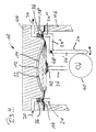
- Fig. 1 shows a schematic partial representation of an exemplary embodiment of a diaphragm pump 10 according to the invention, which may be in particular a diaphragm vacuum pump.
- the membrane pump 10 comprises a via a membrane 12 acted upon pumping chamber 14 and an inlet valve 16 and an outlet valve 18, via a Medium 20 is sucked into the suction chamber 14 in a suction phase and ejected from the suction chamber 14 in a compression phase.
- the inlet valve 16, the outlet valve 18 and the membrane 12 are integrated in a single contiguous component 22 in the form of a common membrane.
- the portion comprising the inlet valve 16 and the portion of the component 22 comprising the outlet valve 18 are positively controlled via an actuator 24.
- At least of the membrane 12 comprehensive portion of the component 22 can be acted upon via a crank mechanism 26.
- the actuators 24 are coupled to this crank mechanism 26.
- the actuators 24 each comprise a pivot arm 28, which is rotatably mounted at one end about a pivot axis 30 and with its other end to a cam 32 (see also Fig. 2 ) of the crank drive 26, and a vertically extending plunger 34 which can be acted upon by the pivot arm 28 and in the vertical direction against the intake valve 16 comprehensive section or the exhaust valve 18 comprehensive portion of the single contiguous component 22 can be pressed.
- both the portion of the component 22 encompassing the inlet valve 16 and the portion of the component 22 which surrounds the outlet valve 18 can be acted upon by the respective actuator 24 in each case against the force of a compression spring 36. After a respective actuation of the inlet valve 16 or outlet valve 18 by the relevant actuator 24, this valve is reset by the associated compression spring 36 again.
- the crank mechanism 26 comprises a connecting rod 38, which is arranged between an eccentric shaft 40 and a single contiguous component 22 acting on the piston member 42.
- the common membrane 22 is clamped between a head cover 44 and the housing 46 of the diaphragm pump 10.
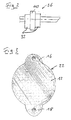
- Fig. 2 shows a schematic side view of the with the connecting rod 38 ( Fig. 1 ) coupled eccentric shaft 40 and the cams 32 of the crank mechanism 26, which are arranged and formed with respect to the eccentric shaft 40 such that the valves 16, 18 controlled in accordance with the controlled by the movement of the connecting rod 38 and thus by the rotating eccentric shaft 40 Pumbrythmus become.
- Fig. 3 is shown in a plan view of the inlet valve 16, the outlet valve 18 and the membrane 12 comprehensive component 22 of the diaphragm pump 10.
- the component 22 in the region of the valves 16, 18 each have a corresponding sealing surface.
- Fig. 4 shows in a schematic partial representation of another exemplary embodiment of a diaphragm pump 10 according to the invention, which differs from that in the Fig. 1 substantially different in that a respective actuator 24 in the present case comprises a rotatable about an axis 48 mounted two-armed lever.
- the lever abuts the eccentric shaft 40 of the crank mechanism 26 with a generally vertically extending portion 24 'and is provided at the free end of a generally horizontally extending portion 24 "with a generally vertically upwardly extending lug 24".
- the inlet valve 16 and the outlet valve 18 can be acted upon accordingly.
- this diaphragm pump 10 has at least substantially the same structure as those of the Fig. 1 , wherein like reference numerals are assigned to corresponding parts.
- the connecting rod 38 (see. Fig. 1 ) of the crank mechanism 26 of a respective diaphragm pump 10 can be directly or for example via a crosshead 50 (see. Fig. 6 ) to be coupled to the component 22 acting on the piston member 42.
- Fig. 5 shows a schematic representation of an exemplary embodiment of a piston drive without crosshead.
- the connecting rod 38 is connected via a piston pin 52 directly to the piston member 42.
- FIG. 6 a schematic representation of an exemplary embodiment of a piston drive with crosshead 50 reproduced.
- the connecting rod 38 is coupled via a crosshead 50 with the individual contiguous component 22 acting on the piston member 42.
- the piston rod 54 is rigidly connected to the bottom of the piston member 42 and a pivot bearing 56 of the crosshead 50 here.
- the pivot bearing 56 is arranged on a sliding block 58 of the crosshead, which is displaceable along a Gleitlagerwandung 60. In such a cross-head assembly, the piston member 42 is kept free of transverse forces.
- the actuators 24 may each also include an electromagnet, a piezo element or another electrically controllable exciter.
- a respective actuator 24 may, for example, be actuated contactlessly, in particular by a crank mechanism, by way of a light barrier, a magnet coil or in another manner. -.-.-.
Landscapes
- Engineering & Computer Science (AREA)
- Mechanical Engineering (AREA)
- General Engineering & Computer Science (AREA)
- Reciprocating Pumps (AREA)
Abstract
Description
- Die vorliegende Erfindung betrifft eine Membranpumpe, insbesondere Membranvakuumpumpe, mit einem über eine Membran beaufschlagbaren Schöpfraum und einem Einlassventil sowie einem Auslassventil, über die ein Medium in einer Saugphase in den Schöpfraum gesaugt und in einer Kompressionsphase aus dem Schöpfraum ausgestoßen wird, wobei das Einlassventil, das Auslassventil und die Membran in einem einzelnen zusammenhängenden Bauteil integriert sind,
- Bei einer derartigen Membranpumpe ist der Schöpfraum durch die Membran zum Antrieb hin hermetisch abgedichtet, so dass weder das geförderte Medium durch Öl verunreinigt werden kann noch aggressive Medien die Mechanik angreifen können. Membranpumpen sind deshalb trockene Verdrängerpumpen. Über die Membran wird der Schöpfraum so beaufschlagt, dass in einer Saugphase das betreffende Medium durch das Einlassventil hindurch in den Schöpfraum gesaugt und in einer Kompressionsphase über das Auslassventil wieder aus dem Schöpfraum ausgestoßen wird. Am oberen Umkehrpunkt der Membran verbleibt ein Totvolumen, dessen Inhalt nicht ausgestoßen wird. Während des darauffolgenden Saughubes expandiert dieses Volumen erneut und füllt den Arbeitsraum teilweise auf, wodurch der erreichbare Enddruck begrenzt wird.
- Mit einer Verdränger-Vakuumpumpe kann kein Verdichtungsverhältnis erzielt werden, das höher ist als das Verhältnis zwischen dem maximalen Arbeitsvolumen und dem Totvolumen. Das Saugvermögen einer solchen Membranpumpe ist eine Funktion der Größe des Schöpfraums, der Drehzahl sowie des Totvolumens. Insbesondere im Ansaugdruckbereich von 1 bis 10 mbar sind die bisher bekannten Membranpumpen den sogenannten Scroll-Pumpen, die ebenfalls zur Gattung der Verdränger-Vakuumpumpen gehören, deutlich unterlegen.
- Aus
DE 297 23 455 U1 ist eine Membranpumpe der eingangs genannten Art bekannt. - Der Erfindung liegt somit die Aufgabe zugrunde, eine verbesserte Membranpumpe der eingangs genannten Art anzugeben, mit der bei möglichst einfach gehaltenem Aufbau ein niedrigerer Enddruck erzielbar ist, der Wartungsaufwand minimiert wird sowie die Herstellungskosten gesenkt werden. Zudem soll insbesondere auch das Saugvermögen der Pumpe erhöht werden.
- Diese Aufgabe wird erfindungsgemäß dadurch gelöst, dass eine Steuerung des Einlassventils und/oder des Auslassventils von einem Antrieb der Membran abgeleitet ist.
- Alternativ oder zusätzlich kann der das Einlassventil umfassende Abschnitt und/oder der das Auslassventil umfassende Abschnitt des zusammenhängenden Bauteils jeweils über einen Aktor zwangsgesteuert sein.
- Nachdem mit dem Einlassventil, dem Auslassventil und der Membran alle zu bewegenden Teile in einem einzelnen zusammenhängenden Bauteil integriert sind, ergibt sich ein wesentlich einfacherer Aufbau, womit entsprechend auch der Wartungsaufwand reduziert wird und die Herstellungskosten gesenkt werden. Zudem können hierdurch Rückströmungen über die Ventile reduziert werden, wodurch sich das Saugvermögen steigern lässt, was sich positiv auf das erreichbare Endvakuum der Membranpumpe auswirkt.
- Das einzelne zusammenhängende Bauteil kann insgesamt als eine Membran ausgebildet sein, die einen dem Schöpfraum zugeordneten Membranabschnitt, der der Membran einer herkömmlichen Membranpumpe entspricht, und für jedes Ventil einen Membranabschnitt umfasst, der die Ventilmembran eines Membranventils bildet.
- Bevorzugt ist vorgesehen, dass die Bewegung des Einlassventils und/oder des Auslassventils durch den Antrieb zwangsgesteuert ist. Dies stellt eine besonders wirksame Maßnahme zur Reduzierung von Rückströmungen dar.
- Wie bereits erwähnt, kann der das Einlassventil umfassende Abschnitt und/oder der das Auslassventil umfassende Abschnitt des zusammenhängenden Bauteils jeweils über einen Aktor zwangsgesteuert sein.
- Durch die Art und Weise der Steuerung, insbesondere durch die Wahl von Steuerzeiten und/oder - wenn Steuernocken vorgesehen sind - durch die Form der Steuernocken, können die Förderleistung und der Enddruck der Membranpumpe stark beeinflusst werden: So kann insbesondere mit dem Hub des Einlassventils der Querschnitt eines Ansaugkanals gezielt verändert werden, was sich direkt auf das Saugvermögen der Membranpumpe auswirkt. Je später das Auslassventil öffnet, desto höher ist die Kompression im Schöpfraum. Eine höhere Kompression wiederum führt zu niedrigeren Drücken im Schöpfraum.
- Bevorzugt ist zumindest der die Membran umfassende Abschnitt des zusammenhängenden Bauteils über einen Kurbeltrieb und/oder einen Linearantrieb beaufschlagbar.
- Die Integration des Einlassventils und des Auslassventils in einem zudem die Membran umfassenden einzelnen zusammenhängenden Bauteil bringt insbesondere auch den Vorteil mit sich, dass die Ventilsteuerung in den Bereich des Kurbeltriebs bzw. Linearantriebs der Membranpumpe verlagert werden kann, womit der Aufbau der Pumpe insgesamt vereinfacht werden kann.
- So ist bevorzugt zumindest ein Aktor mit dem Kurbeltrieb bzw. Linearantrieb der Membranpumpe gekoppelt oder von diesem umfasst.
- Der Kurbeltrieb der Membranpumpe kann insbesondere einen Pleuel umfassen, der zwischen einer Exzenterwelle und einem das zusammenhängende Bauteil beaufschlagenden Kolbenelement angeordnet ist.
- Dabei kann der Pleuel entweder direkt oder auch über einen Kreuzkopf mit dem das zusammenhängende Bauteil beaufschlagenden Kolbenelement gekoppelt sein.
- Ein derartiger Aufbau hat eine lineare Bewegung der Membran zur Folge und führt zu einem kleineren Totvolumen im Schöpfraum.
- Grundsätzlich sind jedoch insbesondere auch solche Ausführungen der Membranpumpe denkbar, bei denen zumindest ein Aktor einen elektrisch ansteuerbaren Erreger umfasst, beispielsweise einen Elektromagneten, ein Piezoelement oder dergleichen.
- Gemäß einer weiteren zweckmäßigen Ausführungsform der erfindungsgemäßen Membranpumpe ist der das Einlassventil umfassende Abschnitt und/oder der das Auslassventil umfassende Abschnitt des einzelnen zusammenhängenden Bauteils durch den jeweiligen Aktor entgegen einer Federkraft beaufschlagbar. Nach einer Betätigung durch einen jeweiligen Aktor kann das jeweilige Ventil dann automatisch durch die Federkraft zurückgestellt werden.
- Ein jeweiliger Aktor kann insbesondere berührungslos ansteuerbar sein, beispielsweise über eine Lichtschranke, eine Magnetspule oder dergleichen.
- Die Erfindung wird im Folgenden anhand von Ausführungsbeispielen unter Bezugnahme auf die Zeichnung näher erläutert; in dieser zeigen:
- Fig. 1
- eine schematische Teildarstellung einer beispielhaften Ausführungsform einer erfindungsgemäßen Membranpumpe,
- Fig. 2
- eine schematische Seitenansicht der Exzenterwelle und der Nocken des Kurbeltriebs der Membranpumpe gemäß
Fig. 1 , - Fig. 3
- eine Draufsicht des das Einlassventil, das Auslassventil und die Membran umfassenden einzelnen zusammenhängenden Bauteils der Membranpumpe gemäß
Fig. 1 , - Fig. 4
- eine schematische Teildarstellung einer weiteren beispielhaften Ausführungsform einer erfindungsgemäßen Membranpumpe,
- Fig. 5
- eine schematische Darstellung eines Kolbentriebs für eine erfindungsgemäße Membranpumpe ohne Kreuzkopf, und
- Fig. 6
- eine schematische Darstellung eines Kolbentriebs für eine erfindungsgemäße Membranpumpe mit Kreuzkopf.
-
Fig. 1 zeigt in schematischer Teildarstellung eine beispielhafte Ausführungsform einer erfindungsgemäßen Membranpumpe 10, bei der es sich insbesondere um eine Membranvakuumpumpe handeln kann. - Die Membranpumpe 10 umfasst einen über eine Membran 12 beaufschlagbaren Schöpfraum 14 und ein Einlassventil 16 sowie ein Auslassventil 18, über die ein Medium 20 in einer Saugphase in den Schöpfraum 14 gesaugt und in einer Kompressionsphase aus dem Schöpfraum 14 ausgestoßen wird.
- Dabei sind, wie dargestellt, das Einlassventil 16, das Auslassventil 18 und die Membran 12 in einem einzelnen zusammenhängenden Bauteil 22 in Form einer gemeinsamen Membran integriert.
- Der das Einlassventil 16 umfassende Abschnitt und der das Auslassventil 18 umfassende Abschnitt des Bauteils 22 ist jeweils über einen Aktor 24 zwangsgesteuert.
- Zumindest der die Membran 12 umfassende Abschnitt des Bauteils 22 ist über einen Kurbeltrieb 26 beaufschlagbar. Die Aktoren 24 sind mit diesem Kurbeltrieb 26 gekoppelt.
- Beim vorliegenden Ausführungsbeispiel umfassen die Aktoren 24 jeweils einen Schwenkarm 28, der an einem Ende um eine Schwenkachse 30 drehbar gelagert ist und mit seinem anderen Ende an einem Nocken 32 (vgl. auch
Fig. 2 ) des Kurbeltriebs 26 anliegt, sowie einen sich in vertikaler Richtung erstreckenden Stößel 34, der durch den Schwenkarm 28 beaufschlagbar und in vertikaler Richtung gegen den das Einlassventil 16 umfassenden Abschnitt bzw. den das Auslassventil 18 umfassenden Abschnitt des einzelnen zusammenhängenden Bauteils 22 pressbar ist. - Dabei ist im vorliegenden Fall sowohl der das Einlassventil 16 umfassende Abschnitt als auch der das Auslassventil 18 umfassende Abschnitt des Bauteils 22 durch den jeweiligen Aktor 24 jeweils entgegen der Kraft einer Druckfeder 36 beaufschlagbar. Nach einer jeweiligen Betätigung des Einlassventils 16 bzw. Auslassventils 18 durch den betreffenden Aktor 24 wird dieses Ventil durch die zugeordnete Druckfeder 36 wieder zurückgestellt.
- Der Kurbeltrieb 26 umfasst einen Pleuel 38, der zwischen einer Exzenterwelle 40 und einem das einzelne zusammenhängende Bauteil 22 beaufschlagenden Kolbenelement 42 angeordnet ist.
- Wie anhand der
Fig. 1 zudem zu erkennen ist, ist die gemeinsame Membran 22 zwischen einem Kopfdeckel 44 und dem Gehäuse 46 der Membranpumpe 10 eingespannt. -
Fig. 2 zeigt in schematischer Seitenansicht die mit dem Pleuel 38 (Fig. 1 ) gekoppelte Exzenterwelle 40 und die Nocken 32 des Kurbeltriebs 26, die in Bezug auf die Exzenterwelle 40 derart angeordnet und ausgebildet sind, dass die Ventile 16, 18 entsprechend dem durch die Bewegung des Pleuels 38 und somit durch die sich drehende Exzenterwelle 40 gesteuerten Pumprythmus gesteuert werden. - In der
Fig. 3 ist in einer Draufsicht das das Einlassventil 16, das Auslassventil 18 und die Membran 12 umfassende Bauteil 22 der Membranpumpe 10 wiedergegeben. WieFig. 3 zeigt, umfasst das Bauteil 22 im Bereich der Ventile 16, 18 jeweils eine entsprechende Dichtfläche. -
Fig. 4 zeigt in schematischer Teildarstellung eine weitere beispielhafte Ausführungsform einer erfindungsgemäßen Membranpumpe 10, die sich von der in derFig. 1 wiedergegebenen Ausführungsform im Wesentlichen dadurch unterscheidet, dass ein jeweiliger Aktor 24 im vorliegenden Fall einen um eine Achse 48 drehbar gelagerten zweiarmigen Hebel umfasst. Der Hebel liegt mit einem sich allgemein in vertikaler Richtung erstreckenden Abschnitt 24' an der Exzenterwelle 40 des Kurbeltriebs 26 an und ist am freien Ende eines sich allgemein horizontal erstreckenden Abschnitts 24" mit einem sich allgemein vertikal nach oben erstreckenden Ansatz 24'" versehen. Über den Ansatz 24'" ist das Einlassventil 16 bzw. das Auslassventil 18 entsprechend beaufschlagbar. - Im Übrigen besitzt diese Membranpumpe 10 zumindest im Wesentlichen wieder denselben Aufbau wie jene der
Fig. 1 , wobei einander entsprechenden Teilen gleiche Bezugszeichen zugeordnet sind. - Der Pleuel 38 (vgl.
Fig. 1 ) des Kurbeltriebs 26 einer jeweiligen Membranpumpe 10 kann direkt oder beispielsweise auch über einen Kreuzkopf 50 (vgl.Fig. 6 ) mit dem das Bauteil 22 beaufschlagenden Kolbenelement 42 gekoppelt sein. -
Fig. 5 zeigt in schematischer Darstellung eine beispielhafte Ausführungsform eines Kolbentriebs ohne Kreuzkopf. Dabei ist der Pleuel 38 über einen Kolbenbolzen 52 unmittelbar mit dem Kolbenelement 42 verbunden. - Demgegenüber ist in der
Fig. 6 in schematischer Darstellung eine beispielhafte Ausführungsform eines Kolbentriebs mit Kreuzkopf 50 wiedergegeben. Hierbei ist der Pleuel 38 über einen Kreuzkopf 50 mit dem das einzelne zusammenhängende Bauteil 22 beaufschlagenden Kolbenelement 42 gekoppelt. - Die Kolbenstange 54 ist hier starr mit dem Boden des Kolbenelements 42 und einem Schwenklager 56 des Kreuzkopfes 50 verbunden. Das Schwenklager 56 ist an einem Gleitschuh 58 des Kreuzkopfes angeordnet, der entlang einer Gleitlagerwandung 60 verschiebbar ist. Bei einer derartigen Kreuzkopfanordnung ist das Kolbenelement 42 von Querkräften freigehalten.
- In alternativen Ausgestaltungen können die Aktoren 24 jeweils auch einen Elektromagneten, ein Piezoelement oder einen anderen elektrisch ansteuerbaren Erreger umfassen.
- Ein jeweiliger Aktor 24 kann beispielsweise über eine Lichtschranke, eine Magnetspule oder auf andere Art und Weise berührungslos insbesondere von einem Kurbeltrieb ansteuerbar sein.-.-.-.
-
- 10
- Membranpumpe
- 12
- Membran
- 14
- Schöpfraum
- 16
- Einlassventil
- 18
- Auslassventil
- 20
- Medium
- 22
- einzelnes zusammenhängendes Bauteil
- 24
- Aktor
- 24'
- Hebelabschnitt
- 24''
- Hebelabschnitt
- 24'''
- Ansatz
- 26
- Kurbeltrieb
- 28
- Schwenkarm
- 30
- Schwenkachse
- 32
- Nocken
- 34
- Stößel
- 36
- Druckfeder
- 38
- Pleuel
- 40
- Exzenterwelle
- 42
- Kolbenelement
- 44
- Kopfdeckel
- 46
- Gehäuse
- 48
- Achse
- 50
- Kreuzkopf
- 52
- Kolbenbolzen
- 54
- Kolbenstange
- 56
- Schwenklager
- 58
- Gleitschuh
- 60
- Gleitlagerwandung
Claims (10)
- Membranpumpe (10), insbesondere Membranvakuumpumpe, mit einem über eine Membran (12) beaufschlagbaren Schöpfraum (14) und einem Einlassventil (16) sowie einem Auslassventil (18), über die ein Medium (20) in einer Saugphase in den Schöpfraum (14) gesaugt und in einer Kompressionsphase aus dem Schöpfraum (14) ausgestoßen wird, wobei das Einlassventil (16), das Auslassventil (18) und die Membran (12) in einem einzelnen zusammenhängenden Bauteil (22) integriert sind
dadurch gekennzeichnet, dass eine Steuerung des Einlassventils (16) und/oder des Auslassventils (18) von einem Antrieb (26) der Membran (12) abgeleitet ist. - Membranpumpe nach Anspruch 1,
dadurch gekennzeichnet, dass die Bewegung des Einlassventils (16) und/oder des Auslassventils (18) durch den Antrieb (26) zwangsgesteuert ist. - Membranpumpe nach Anspruch 1 oder 2,
dadurch gekennzeichnet, dass der das Einlassventil (16) umfassende Abschnitt und/oder der das Auslassventil (18) umfassende Abschnitt des einzelnen zusammenhängenden Bauteils (22) jeweils über einen Aktor (24) zwangsgesteuert ist. - Membranpumpe nach einem der vorstehenden Ansprüche,
dadurch gekennzeichnet, dass zumindest der die Membran (12) umfassende Abschnitt des einzelnen zusammenhängenden Bauteils (22) über einen Kurbeltrieb (26) und/oder einen Linearantrieb beaufschlagbar ist. - Membranpumpe nach Anspruch 4,
dadurch gekennzeichnet, dass zumindest ein Aktor (24) mit dem Kurbeltrieb (26) bzw. Linearantrieb gekoppelt oder von diesem umfasst ist. - Membranpumpe nach Anspruch 4 oder 5,
dadurch gekennzeichnet , dass der Kurbeltrieb (26) einen Pleuel (38) umfasst, der zwischen einer Exzenterwelle (40) und einem das einzelne zusammenhängende Bauteil (22) beaufschlagenden Kolbenelement (42) angeordnet ist. - Membranpumpe nach Anspruch 6,
dadurch gekennzeichnet , dass der Pleuel (38) über einen Kreuzkopf (50) mit dem das einzelne zusammenhängende Bauteil (22) beaufschlagenden Kolbenelement (42) gekoppelt ist. - Membranpumpe nach einem der Ansprüche 3 bis 7,
dadurch gekennzeichnet, dass zumindest ein Aktor (24) einen elektrisch ansteuerbaren Erreger umfasst, insbesondere einen Elektromagneten oder ein Piezoelement. - Membranpumpe nach einem der vorstehenden Ansprüche,
dadurch gekennzeichnet, dass der das Einlassventil (16) umfassende Abschnitt und/oder der das Auslassventil (18) umfassende Abschnitt des einzelnen zusammenhängenden Bauteils (22) durch den jeweiligen Aktor (24) entgegen einer Federkraft beaufschlagbar ist. - Membranpumpe nach einem der Ansprüche 3 bis 9,
dadurch gekennzeichnet, dass ein jeweiliger Aktor (24) berührungslos ansteuerbar ist, insbesondere über eine Lichtschranke oder eine Magnetspule.
Applications Claiming Priority (1)
| Application Number | Priority Date | Filing Date | Title |
|---|---|---|---|
| DE102014103459.7A DE102014103459A1 (de) | 2014-03-13 | 2014-03-13 | Membranpumpe |
Publications (3)
| Publication Number | Publication Date |
|---|---|
| EP2918835A1 true EP2918835A1 (de) | 2015-09-16 |
| EP2918835B1 EP2918835B1 (de) | 2017-03-29 |
| EP2918835B2 EP2918835B2 (de) | 2020-04-29 |
Family
ID=52358666
Family Applications (1)
| Application Number | Title | Priority Date | Filing Date |
|---|---|---|---|
| EP15151943.6A Active EP2918835B2 (de) | 2014-03-13 | 2015-01-21 | Membranpumpe |
Country Status (2)
| Country | Link |
|---|---|
| EP (1) | EP2918835B2 (de) |
| DE (1) | DE102014103459A1 (de) |
Cited By (1)
| Publication number | Priority date | Publication date | Assignee | Title |
|---|---|---|---|---|
| CN112811519A (zh) * | 2021-01-06 | 2021-05-18 | 杭州电子科技大学 | 一种净水器水处理增压泵能量回收系统 |
Families Citing this family (1)
| Publication number | Priority date | Publication date | Assignee | Title |
|---|---|---|---|---|
| DE102021204407A1 (de) | 2021-05-03 | 2022-11-03 | Robert Bosch Gesellschaft mit beschränkter Haftung | Verfahren zum Betreiben einer Pumpe und Fluid-Versorgungssystem |
Citations (4)
| Publication number | Priority date | Publication date | Assignee | Title |
|---|---|---|---|---|
| DE29723455U1 (de) | 1997-12-10 | 1998-09-17 | ASF THOMAS Industries GmbH, 82178 Puchheim | Membrane für Membranpumpe |
| WO2002023043A1 (de) * | 2000-09-14 | 2002-03-21 | Beenker Jan W | Verfahren und maschine zur förderung von medien |
| EP2354546A1 (de) * | 2010-02-09 | 2011-08-10 | Vacuubrand Gmbh + Co Kg | Membranvakuumpumpe |
| DE102010019057A1 (de) * | 2010-05-03 | 2011-11-03 | Wmf Württembergische Metallwarenfabrik Ag | Fluidpumpe |
Family Cites Families (3)
| Publication number | Priority date | Publication date | Assignee | Title |
|---|---|---|---|---|
| DE809457C (de) * | 1947-03-12 | 1951-07-30 | Marcel Rene Armand Chabay | Kolbenverdichter |
| US2785638A (en) * | 1954-04-08 | 1957-03-19 | Clifford B Moller | Force pump for slurries |
| US4411603A (en) * | 1981-06-24 | 1983-10-25 | Cordis Dow Corp. | Diaphragm type blood pump for medical use |
-
2014
- 2014-03-13 DE DE102014103459.7A patent/DE102014103459A1/de not_active Withdrawn
-
2015
- 2015-01-21 EP EP15151943.6A patent/EP2918835B2/de active Active
Patent Citations (4)
| Publication number | Priority date | Publication date | Assignee | Title |
|---|---|---|---|---|
| DE29723455U1 (de) | 1997-12-10 | 1998-09-17 | ASF THOMAS Industries GmbH, 82178 Puchheim | Membrane für Membranpumpe |
| WO2002023043A1 (de) * | 2000-09-14 | 2002-03-21 | Beenker Jan W | Verfahren und maschine zur förderung von medien |
| EP2354546A1 (de) * | 2010-02-09 | 2011-08-10 | Vacuubrand Gmbh + Co Kg | Membranvakuumpumpe |
| DE102010019057A1 (de) * | 2010-05-03 | 2011-11-03 | Wmf Württembergische Metallwarenfabrik Ag | Fluidpumpe |
Non-Patent Citations (1)
| Title |
|---|
| FINK D: "MEMBRANDOSIERER MIT ZWANGSGESTEUERTER VENTILTECHNIK", WAGEN UND DOSIEREN, VERLAGSGESELLSCHAFT KEPPLER, MAINZ, DE, vol. 29, no. 1, 1 February 1998 (1998-02-01), pages 14 - 19, XP000779790, ISSN: 0342-5916 * |
Cited By (2)
| Publication number | Priority date | Publication date | Assignee | Title |
|---|---|---|---|---|
| CN112811519A (zh) * | 2021-01-06 | 2021-05-18 | 杭州电子科技大学 | 一种净水器水处理增压泵能量回收系统 |
| CN112811519B (zh) * | 2021-01-06 | 2022-07-01 | 杭州电子科技大学 | 一种净水器水处理增压泵能量回收系统 |
Also Published As
| Publication number | Publication date |
|---|---|
| EP2918835B1 (de) | 2017-03-29 |
| EP2918835B2 (de) | 2020-04-29 |
| DE102014103459A1 (de) | 2015-09-17 |
Similar Documents
| Publication | Publication Date | Title |
|---|---|---|
| DE102010003218A1 (de) | Verfahren zum Steuern und/oder Regeln einer Dosierpumpe | |
| EP3482076B1 (de) | Zylinderkopfdeckel für einen kältemittelkompressor | |
| DE102008062483A1 (de) | Axialkolbenmaschine mit Pulsationsminderung | |
| EP2725226A1 (de) | Kolbenpumpe | |
| WO2010055100A1 (de) | Pumpeneinheit für eine hochdruckpumpe | |
| DE1673517C3 (de) | Selbsttätiger hydraulischer Druckbegrenzer für Membrankompressoren und -pumpen | |
| EP2918835B1 (de) | Membranpumpe | |
| WO2006037671A1 (de) | Radialkolbenpumpe | |
| DE10018498B4 (de) | Ventilanordnung | |
| EP4004370B1 (de) | Ventilvorrichtung für einen hubkolbenverdichter | |
| EP2354546B1 (de) | Membranvakuumpumpe | |
| DE102014000469B4 (de) | Schraubenverdichter | |
| EP3119596B1 (de) | Vorrichtung zum abdichten und aufpumpen aufblasbarer gegenstände | |
| DE3218960C2 (de) | ||
| DE102014204496A1 (de) | Drehschieberanordnung | |
| DE60100149T2 (de) | Verdichtereinlassventil | |
| DE102012024704A1 (de) | Rollkolbenverdichter mit veränderbarer Förderleistung | |
| DE102012012735B3 (de) | Piezoelektrisch angetriebene Hubkolbenpumpe mit Squiggle-Motor zum Einbau in autonome Funktionsstrukturen | |
| EP1831547B1 (de) | Kolbenpumpe mit wenigstens einem stufenkolbenelement | |
| DE1653586C3 (de) | Pumpe mit hin- und herbewegbarem Kolben | |
| DE102008012538A1 (de) | Hydraulische Kolbenmaschine | |
| EP2835533A1 (de) | Lösungsmittelpumpe | |
| EP2456978B1 (de) | Verfahren zur fördermengenregelung und hubkolben-kompressor mit fördermengenregelung | |
| DE102006014333A1 (de) | Pumpe für kryogene Medien | |
| DE2710778B2 (de) | Dichtungseinrichtung für den Tauchkolben einer Hochdruckpumpe |
Legal Events
| Date | Code | Title | Description |
|---|---|---|---|
| PUAI | Public reference made under article 153(3) epc to a published international application that has entered the european phase |
Free format text: ORIGINAL CODE: 0009012 |
|
| AK | Designated contracting states |
Kind code of ref document: A1 Designated state(s): AL AT BE BG CH CY CZ DE DK EE ES FI FR GB GR HR HU IE IS IT LI LT LU LV MC MK MT NL NO PL PT RO RS SE SI SK SM TR |
|
| AX | Request for extension of the european patent |
Extension state: BA ME |
|
| 17P | Request for examination filed |
Effective date: 20160316 |
|
| RBV | Designated contracting states (corrected) |
Designated state(s): AL AT BE BG CH CY CZ DE DK EE ES FI FR GB GR HR HU IE IS IT LI LT LU LV MC MK MT NL NO PL PT RO RS SE SI SK SM TR |
|
| RIC1 | Information provided on ipc code assigned before grant |
Ipc: F04B 39/08 20060101AFI20160830BHEP Ipc: F04B 43/00 20060101ALI20160830BHEP Ipc: F04B 45/04 20060101ALI20160830BHEP Ipc: F04B 43/02 20060101ALI20160830BHEP |
|
| GRAP | Despatch of communication of intention to grant a patent |
Free format text: ORIGINAL CODE: EPIDOSNIGR1 |
|
| INTG | Intention to grant announced |
Effective date: 20161014 |
|
| GRAS | Grant fee paid |
Free format text: ORIGINAL CODE: EPIDOSNIGR3 |
|
| STAA | Information on the status of an ep patent application or granted ep patent |
Free format text: STATUS: GRANT OF PATENT IS INTENDED |
|
| GRAA | (expected) grant |
Free format text: ORIGINAL CODE: 0009210 |
|
| STAA | Information on the status of an ep patent application or granted ep patent |
Free format text: STATUS: THE PATENT HAS BEEN GRANTED |
|
| AK | Designated contracting states |
Kind code of ref document: B1 Designated state(s): AL AT BE BG CH CY CZ DE DK EE ES FI FR GB GR HR HU IE IS IT LI LT LU LV MC MK MT NL NO PL PT RO RS SE SI SK SM TR |
|
| REG | Reference to a national code |
Ref country code: GB Ref legal event code: FG4D Free format text: NOT ENGLISH |
|
| REG | Reference to a national code |
Ref country code: CH Ref legal event code: EP |
|
| REG | Reference to a national code |
Ref country code: AT Ref legal event code: REF Ref document number: 880042 Country of ref document: AT Kind code of ref document: T Effective date: 20170415 |
|
| REG | Reference to a national code |
Ref country code: IE Ref legal event code: FG4D Free format text: LANGUAGE OF EP DOCUMENT: GERMAN |
|
| REG | Reference to a national code |
Ref country code: DE Ref legal event code: R096 Ref document number: 502015000762 Country of ref document: DE |
|
| PG25 | Lapsed in a contracting state [announced via postgrant information from national office to epo] |
Ref country code: LT Free format text: LAPSE BECAUSE OF FAILURE TO SUBMIT A TRANSLATION OF THE DESCRIPTION OR TO PAY THE FEE WITHIN THE PRESCRIBED TIME-LIMIT Effective date: 20170329 Ref country code: GR Free format text: LAPSE BECAUSE OF FAILURE TO SUBMIT A TRANSLATION OF THE DESCRIPTION OR TO PAY THE FEE WITHIN THE PRESCRIBED TIME-LIMIT Effective date: 20170630 Ref country code: HR Free format text: LAPSE BECAUSE OF FAILURE TO SUBMIT A TRANSLATION OF THE DESCRIPTION OR TO PAY THE FEE WITHIN THE PRESCRIBED TIME-LIMIT Effective date: 20170329 Ref country code: FI Free format text: LAPSE BECAUSE OF FAILURE TO SUBMIT A TRANSLATION OF THE DESCRIPTION OR TO PAY THE FEE WITHIN THE PRESCRIBED TIME-LIMIT Effective date: 20170329 Ref country code: NO Free format text: LAPSE BECAUSE OF FAILURE TO SUBMIT A TRANSLATION OF THE DESCRIPTION OR TO PAY THE FEE WITHIN THE PRESCRIBED TIME-LIMIT Effective date: 20170629 |
|
| REG | Reference to a national code |
Ref country code: NL Ref legal event code: MP Effective date: 20170329 |
|
| PG25 | Lapsed in a contracting state [announced via postgrant information from national office to epo] |
Ref country code: BG Free format text: LAPSE BECAUSE OF FAILURE TO SUBMIT A TRANSLATION OF THE DESCRIPTION OR TO PAY THE FEE WITHIN THE PRESCRIBED TIME-LIMIT Effective date: 20170629 Ref country code: RS Free format text: LAPSE BECAUSE OF FAILURE TO SUBMIT A TRANSLATION OF THE DESCRIPTION OR TO PAY THE FEE WITHIN THE PRESCRIBED TIME-LIMIT Effective date: 20170329 Ref country code: LV Free format text: LAPSE BECAUSE OF FAILURE TO SUBMIT A TRANSLATION OF THE DESCRIPTION OR TO PAY THE FEE WITHIN THE PRESCRIBED TIME-LIMIT Effective date: 20170329 Ref country code: SE Free format text: LAPSE BECAUSE OF FAILURE TO SUBMIT A TRANSLATION OF THE DESCRIPTION OR TO PAY THE FEE WITHIN THE PRESCRIBED TIME-LIMIT Effective date: 20170329 |
|
| PG25 | Lapsed in a contracting state [announced via postgrant information from national office to epo] |
Ref country code: NL Free format text: LAPSE BECAUSE OF FAILURE TO SUBMIT A TRANSLATION OF THE DESCRIPTION OR TO PAY THE FEE WITHIN THE PRESCRIBED TIME-LIMIT Effective date: 20170329 |
|
| PG25 | Lapsed in a contracting state [announced via postgrant information from national office to epo] |
Ref country code: EE Free format text: LAPSE BECAUSE OF FAILURE TO SUBMIT A TRANSLATION OF THE DESCRIPTION OR TO PAY THE FEE WITHIN THE PRESCRIBED TIME-LIMIT Effective date: 20170329 Ref country code: CZ Free format text: LAPSE BECAUSE OF FAILURE TO SUBMIT A TRANSLATION OF THE DESCRIPTION OR TO PAY THE FEE WITHIN THE PRESCRIBED TIME-LIMIT Effective date: 20170329 Ref country code: RO Free format text: LAPSE BECAUSE OF FAILURE TO SUBMIT A TRANSLATION OF THE DESCRIPTION OR TO PAY THE FEE WITHIN THE PRESCRIBED TIME-LIMIT Effective date: 20170329 Ref country code: ES Free format text: LAPSE BECAUSE OF FAILURE TO SUBMIT A TRANSLATION OF THE DESCRIPTION OR TO PAY THE FEE WITHIN THE PRESCRIBED TIME-LIMIT Effective date: 20170329 Ref country code: SK Free format text: LAPSE BECAUSE OF FAILURE TO SUBMIT A TRANSLATION OF THE DESCRIPTION OR TO PAY THE FEE WITHIN THE PRESCRIBED TIME-LIMIT Effective date: 20170329 |
|
| PG25 | Lapsed in a contracting state [announced via postgrant information from national office to epo] |
Ref country code: IS Free format text: LAPSE BECAUSE OF FAILURE TO SUBMIT A TRANSLATION OF THE DESCRIPTION OR TO PAY THE FEE WITHIN THE PRESCRIBED TIME-LIMIT Effective date: 20170729 Ref country code: PL Free format text: LAPSE BECAUSE OF FAILURE TO SUBMIT A TRANSLATION OF THE DESCRIPTION OR TO PAY THE FEE WITHIN THE PRESCRIBED TIME-LIMIT Effective date: 20170329 Ref country code: SM Free format text: LAPSE BECAUSE OF FAILURE TO SUBMIT A TRANSLATION OF THE DESCRIPTION OR TO PAY THE FEE WITHIN THE PRESCRIBED TIME-LIMIT Effective date: 20170329 |
|
| REG | Reference to a national code |
Ref country code: DE Ref legal event code: R026 Ref document number: 502015000762 Country of ref document: DE |
|
| PLBI | Opposition filed |
Free format text: ORIGINAL CODE: 0009260 |
|
| PLAX | Notice of opposition and request to file observation + time limit sent |
Free format text: ORIGINAL CODE: EPIDOSNOBS2 |
|
| PG25 | Lapsed in a contracting state [announced via postgrant information from national office to epo] |
Ref country code: DK Free format text: LAPSE BECAUSE OF FAILURE TO SUBMIT A TRANSLATION OF THE DESCRIPTION OR TO PAY THE FEE WITHIN THE PRESCRIBED TIME-LIMIT Effective date: 20170329 |
|
| 26 | Opposition filed |
Opponent name: KNF NEUBERGER GMBH Effective date: 20171221 |
|
| PLBB | Reply of patent proprietor to notice(s) of opposition received |
Free format text: ORIGINAL CODE: EPIDOSNOBS3 |
|
| PG25 | Lapsed in a contracting state [announced via postgrant information from national office to epo] |
Ref country code: SI Free format text: LAPSE BECAUSE OF FAILURE TO SUBMIT A TRANSLATION OF THE DESCRIPTION OR TO PAY THE FEE WITHIN THE PRESCRIBED TIME-LIMIT Effective date: 20170329 |
|
| REG | Reference to a national code |
Ref country code: CH Ref legal event code: PL |
|
| PG25 | Lapsed in a contracting state [announced via postgrant information from national office to epo] |
Ref country code: MT Free format text: LAPSE BECAUSE OF FAILURE TO SUBMIT A TRANSLATION OF THE DESCRIPTION OR TO PAY THE FEE WITHIN THE PRESCRIBED TIME-LIMIT Effective date: 20170329 |
|
| PG25 | Lapsed in a contracting state [announced via postgrant information from national office to epo] |
Ref country code: LU Free format text: LAPSE BECAUSE OF NON-PAYMENT OF DUE FEES Effective date: 20180121 Ref country code: FR Free format text: LAPSE BECAUSE OF NON-PAYMENT OF DUE FEES Effective date: 20180131 |
|
| REG | Reference to a national code |
Ref country code: IE Ref legal event code: MM4A |
|
| REG | Reference to a national code |
Ref country code: FR Ref legal event code: ST Effective date: 20180928 |
|
| REG | Reference to a national code |
Ref country code: BE Ref legal event code: MM Effective date: 20180131 |
|
| PG25 | Lapsed in a contracting state [announced via postgrant information from national office to epo] |
Ref country code: CH Free format text: LAPSE BECAUSE OF NON-PAYMENT OF DUE FEES Effective date: 20180131 Ref country code: BE Free format text: LAPSE BECAUSE OF NON-PAYMENT OF DUE FEES Effective date: 20180131 Ref country code: LI Free format text: LAPSE BECAUSE OF NON-PAYMENT OF DUE FEES Effective date: 20180131 |
|
| PG25 | Lapsed in a contracting state [announced via postgrant information from national office to epo] |
Ref country code: IE Free format text: LAPSE BECAUSE OF NON-PAYMENT OF DUE FEES Effective date: 20180121 |
|
| PG25 | Lapsed in a contracting state [announced via postgrant information from national office to epo] |
Ref country code: MC Free format text: LAPSE BECAUSE OF FAILURE TO SUBMIT A TRANSLATION OF THE DESCRIPTION OR TO PAY THE FEE WITHIN THE PRESCRIBED TIME-LIMIT Effective date: 20170329 |
|
| PUAH | Patent maintained in amended form |
Free format text: ORIGINAL CODE: 0009272 |
|
| STAA | Information on the status of an ep patent application or granted ep patent |
Free format text: STATUS: PATENT MAINTAINED AS AMENDED |
|
| PG25 | Lapsed in a contracting state [announced via postgrant information from national office to epo] |
Ref country code: TR Free format text: LAPSE BECAUSE OF FAILURE TO SUBMIT A TRANSLATION OF THE DESCRIPTION OR TO PAY THE FEE WITHIN THE PRESCRIBED TIME-LIMIT Effective date: 20170329 |
|
| 27A | Patent maintained in amended form |
Effective date: 20200429 |
|
| AK | Designated contracting states |
Kind code of ref document: B2 Designated state(s): AL AT BE BG CH CY CZ DE DK EE ES FI FR GB GR HR HU IE IS IT LI LT LU LV MC MK MT NL NO PL PT RO RS SE SI SK SM TR |
|
| REG | Reference to a national code |
Ref country code: DE Ref legal event code: R102 Ref document number: 502015000762 Country of ref document: DE |
|
| PG25 | Lapsed in a contracting state [announced via postgrant information from national office to epo] |
Ref country code: PT Free format text: LAPSE BECAUSE OF FAILURE TO SUBMIT A TRANSLATION OF THE DESCRIPTION OR TO PAY THE FEE WITHIN THE PRESCRIBED TIME-LIMIT Effective date: 20170329 |
|
| PG25 | Lapsed in a contracting state [announced via postgrant information from national office to epo] |
Ref country code: MK Free format text: LAPSE BECAUSE OF NON-PAYMENT OF DUE FEES Effective date: 20170329 Ref country code: CY Free format text: LAPSE BECAUSE OF FAILURE TO SUBMIT A TRANSLATION OF THE DESCRIPTION OR TO PAY THE FEE WITHIN THE PRESCRIBED TIME-LIMIT Effective date: 20170329 Ref country code: HU Free format text: LAPSE BECAUSE OF FAILURE TO SUBMIT A TRANSLATION OF THE DESCRIPTION OR TO PAY THE FEE WITHIN THE PRESCRIBED TIME-LIMIT; INVALID AB INITIO Effective date: 20150121 |
|
| PG25 | Lapsed in a contracting state [announced via postgrant information from national office to epo] |
Ref country code: AL Free format text: LAPSE BECAUSE OF FAILURE TO SUBMIT A TRANSLATION OF THE DESCRIPTION OR TO PAY THE FEE WITHIN THE PRESCRIBED TIME-LIMIT Effective date: 20170329 |
|
| REG | Reference to a national code |
Ref country code: AT Ref legal event code: MM01 Ref document number: 880042 Country of ref document: AT Kind code of ref document: T Effective date: 20200121 |
|
| PG25 | Lapsed in a contracting state [announced via postgrant information from national office to epo] |
Ref country code: AT Free format text: LAPSE BECAUSE OF NON-PAYMENT OF DUE FEES Effective date: 20200121 |
|
| PGFP | Annual fee paid to national office [announced via postgrant information from national office to epo] |
Ref country code: GB Payment date: 20260123 Year of fee payment: 12 |
|
| PGFP | Annual fee paid to national office [announced via postgrant information from national office to epo] |
Ref country code: DE Payment date: 20260328 Year of fee payment: 12 |
|
| PGFP | Annual fee paid to national office [announced via postgrant information from national office to epo] |
Ref country code: IT Payment date: 20260126 Year of fee payment: 12 |