EP2918525B1 - Method for destacking objects stored on a mounting and associated device - Google Patents
Method for destacking objects stored on a mounting and associated device Download PDFInfo
- Publication number
- EP2918525B1 EP2918525B1 EP15159041.1A EP15159041A EP2918525B1 EP 2918525 B1 EP2918525 B1 EP 2918525B1 EP 15159041 A EP15159041 A EP 15159041A EP 2918525 B1 EP2918525 B1 EP 2918525B1
- Authority
- EP
- European Patent Office
- Prior art keywords
- sensor
- mark
- objects
- stack
- bags
- Prior art date
- Legal status (The legal status is an assumption and is not a legal conclusion. Google has not performed a legal analysis and makes no representation as to the accuracy of the status listed.)
- Active
Links
Images


Classifications
-
- B—PERFORMING OPERATIONS; TRANSPORTING
- B65—CONVEYING; PACKING; STORING; HANDLING THIN OR FILAMENTARY MATERIAL
- B65G—TRANSPORT OR STORAGE DEVICES, e.g. CONVEYORS FOR LOADING OR TIPPING, SHOP CONVEYOR SYSTEMS OR PNEUMATIC TUBE CONVEYORS
- B65G59/00—De-stacking of articles
-
- B—PERFORMING OPERATIONS; TRANSPORTING
- B65—CONVEYING; PACKING; STORING; HANDLING THIN OR FILAMENTARY MATERIAL
- B65G—TRANSPORT OR STORAGE DEVICES, e.g. CONVEYORS FOR LOADING OR TIPPING, SHOP CONVEYOR SYSTEMS OR PNEUMATIC TUBE CONVEYORS
- B65G59/00—De-stacking of articles
- B65G59/02—De-stacking from the top of the stack
- B65G59/04—De-stacking from the top of the stack by suction or magnetic devices
- B65G59/045—De-stacking from the top of the stack by suction or magnetic devices with a stepwise upward movement of the stack
Definitions
- the present invention relates to a method for depiling objects such as bags or blanks of cardboard boxes stored on a support and to an associated device.
- the present invention relates more specifically to the supply station empty bags of a bagging chain.
- a bag consists of an envelope of flexible material forming a tube whose one end, the bottom, is closed, while the other end is open prior to filling and is closed after the filling.
- the envelope may be made from at least one sheet or complex of sheets of various materials, for example paper, cotton, plastic or other.
- the bags are manufactured on a first site and then are filled on a second site.
- the first site can also be printed so as to affix on the sides of the bags the appropriate information relating to the product that will be packaged there.
- the bags are stored according to a palletizing plan (hereinafter referred to as a storage plan) on pallets in order to be transferred to the filling site.
- a palletizing plan hereinafter referred to as a storage plan
- the bags come out of the production and printing line one after the other, all oriented in the same way.
- the bags 10 are then grouped together in stacks 12 which are grouped in layers 14, the layers being stacked on each other on a support 16 such as a pallet.
- the bags of the same pile are all oriented in the same way.
- batteries all include the same number of bags.
- the stacks 12 of one and the same layer are not all oriented in the same way, so that the bags from one stack to another are not oriented in the same way.
- the batteries 12 are not arranged in the same way.
- the formation of a pallet of bags is automated and performed by a controller that respects a storage plan.
- the bags must be introduced one after another and must imperatively all be oriented in the same way.
- a feeding station of a bagging chain comprises an automaton capable of grasping a bag at the level of the pallet of bags, of the transfer to the bagging chain, taking care to orient it correctly.
- the automaton knows in theory the position of each bag of the pallet and should therefore be able to correctly capture each bag and deposit it correctly oriented at the level of the bagging chain according to a destocking plan.
- the destocking plan can not be applied.
- the destocking plan is not applied and the controller comprises at the gripper a camera for filming the top of the pallet bags, an image recognition software to determine the position of the bags and their orientations.
- the camera captures an image from the top of the pallet. This image is then analyzed by the recognition software image to determine the position of a bag to enter and its orientation. Since the position of the bag is known, the automaton determines its trajectory to come straight up to the bag to be grasped, seize it and then transport it to the bagging chain, having taken care eventually to modify its orientation if necessary.
- the image recognition software is relatively complex to set and require that the captured image is as regular as possible in terms of rendering.
- the rendering of the images is not regular, the surrounding light varies according to particular hours of the day, the bags reflecting more or less this light depending on the material used to make them.
- this procedure requiring an image analysis can not be implemented.
- image recognition software is relatively expensive.
- US 2013/0096713 A1 discloses a method according to the preamble of claim 1.
- the present invention aims to overcome the disadvantages of the prior art.
- the subject of the invention is a method of unstacking objects stored according to several stacks, each stack comprising several objects, said objects being oriented in the same manner in each stack, said unstacking method consisting in grasping by means of at least one gripper, controlled by a control system, one by one the objects in order to deposit them in a given orientation at an outlet, each object comprising at least one mark positioned identically for all the objects, characterized in that the method comprises using mark detection means comprising at least a first sensor configured to detect a variation of a physical quantity when a mark goes into its measuring field, moving said first sensor along a secant path with the theoretical position of the mark of the object of the stack being unstacked to determine if the stack being unstacked is complete.
- the invention also relates to a feeding station according to claim 6.
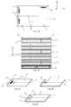
- bags 10 are shown stored on a support 16, for example a pallet.
- Bags 10 are stored flat. They are grouped by batteries 12 which are grouped in layers 14, the layers being stacked on each other on the support 16.
- each bag 10 comprises a bottom 18, an opening 20 and a longitudinal axis 22 perpendicular to the edges delimiting the bottom and the opening.
- a device 24 for unstacking bags 10 which comprises an unstacking zone 26 at which is positioned a support 16 and an outlet 28 at which the bags are unstacked and are positioned in a given orientation.
- the output of the device 24 corresponds to the bag feeding of a bagging chain materialized by a roller conveyor 30.
- the bags 10 are all oriented in the same manner.
- the orientation of a bag is characterized by the direction of its longitudinal axis 22 and the direction of the bag, namely the position of the opening 20 relative to the bottom 18 along the longitudinal axis 22.
- the longitudinal axis 22 each bag must be parallel to an exit direction marked by an arrow 32 on the figure 5 and the opening 20 positioned in an exit direction shown by the arrow 32, the opening 20 being positioned at the head of the boom 32 and the bottom 18 at the tail of the boom 32.
- the exit direction may be parallel or perpendicular to the direction of travel of the bags at the exit.
- the exit direction 32 is perpendicular to the traveling direction 36.
- each layer 14 of stacks 12 of bags comprises three stacks 12.
- Each stack 12 comprises a theoretical number N of bags 10.
- each layer 14 comprises four stacks of bags.
- the bags are stored on the support according to a storage plan.
- the positioning and orientation of the bags are defined with respect to an orthonormal coordinate system X 0, Y 0, Z 0 of the storage plan.
- the support 16 comprises a planar top surface (on which the bags are stacked) which corresponds to the plane X 0 Y 0 , the direction Z 0 being perpendicular to this upper surface of the support 16.
- the upper surface is square or rectangular, the X 0 direction being parallel to certain edges of the upper surface and the Y 0 direction parallel to other edges.
- the edges of the bags are parallel to the edges of the upper surface of the support 16, the edges of the bags are parallel to the axis X 0 or Y 0 .
- the bags of the same pile are all oriented in the same way and the number of bags per stack is theoretically identical.
- the destocking plan corresponds to the storage plan, only the gripping order of the bags being reversed.
- the bags are positioned and oriented according to a reference identical to the reference X 0 , Y 0 , Z 0 of the storage plan.
- the unstacking device 24 comprises at least one gripper 38 configured to move in a reference X 1 , Y 1 , Z 1 of the unstacking device.
- the direction X 1 is arranged in a plane parallel to the plane of depositing the bags and parallel to the direction of travel 36.
- the direction Y 1 is arranged in a plan of deposit of the bags and perpendicular to the direction of Scrolling 36.
- the plane of removal of the bags corresponds to the horizontal plane.
- the direction Z 1 corresponds to the vertical direction.
- the unstacking zone 26 comprises a flat deposition surface 40 on which is placed a support 16 which is preferably arranged in a plane X 1 Y 1 , ie horizontally.
- the gripper 38 depilates the bags by applying the destocking plan.
- it comprises means for determining the position of the coordinate system X 0 , Y 0 , Z 0 of the storage plane in the X 1 , Y 1 , Z 1 reference of the unstacking device.
- the upper surface of the support 16 and the deposition surface 40 are parallel so that the Z 0 and Z 1 axes are parallel.
- the unstacking device comprises means for positioning the carrier so that the X 0 axis is parallel to the axis X 1 or Y 1.
- the unstacking device may comprise a polarizer so that the axis X 0 is parallel to the axis X 1 .
- the means for determining the position of the coordinate system X 0 , Y 0 , Z 0 of the storage plane in the X 1 , Y 1 , Z 1 coordinate system of the unstacking device comprise means 42 for detecting a mark on a bag.
- each bag 10 comprises at least one mark 44. All the bags of the same pallet comprise the same or the same marks.
- the mark 44 is in the form of a marker whose color provides a color contrast with the rest of the bag.
- the mark or marks 44 are positioned on the bag so as to identify the orientation of the bag.
- the bag 10 comprises a mark longer than wide, for example rectangular and the angle formed by the direction of the mark L44 corresponding to its length and the longitudinal axis 22 is constant from one bag to another.
- the direction of the mark L44 is perpendicular to the longitudinal axis 22.
- the mark 44 has a width of 1 to 2 cm and a length of the order of 5 to 15 cm.
- the bag comprises two marks 44, preferably identical (square according to the example shown), offset in an offset direction and the angle formed by the offset direction and the longitudinal axis 22 is constant from a bag to the 'other.
- the offset direction is parallel to the longitudinal axis 22.
- the offset direction of the two marks 44 is perpendicular to the longitudinal axis 22.
- each bag comprises at least one fold line 45 allowing the head of the bag to be folded and glued after filling the bag so as to close it.
- the mark or marks 44 is or are arranged between the edge 47 of the opening 20 and the fold line 45.
- the mark or marks 44 are not positioned in the middle position relative to the bottom 18 and the opening 20.
- the mark or marks are arranged near the opening 20. In this case, when the bag is folded to close the opening, the mark or marks are no longer visible after closing the bag.
- the detection means 42 take an image of the top of the support 16 on which the bags are stacked.
- this image is analyzed to determine the position of the X 0 , Y 0 , Z 0 coordinate of the storage plane in the X 1 , Y 1 , Z 1 coordinate system as a function of the position of the marks.
- the image is compared with a reference image in order to determine the angular offset between the reference X 0 , Y 0 , Z 0 of the storage plane and the reference X 1 Y 1 Z 1 of the unstacking device, the axes Zo and Z 1 being parallel.
- the unstacking device can apply the destocking plan taking into account this angular offset to correctly orient the bags.
- the method uses only one image analysis at the beginning of the process. By following, he can apply the destocking plan and does not need to make an image analysis with each bag entered. According to another advantage, the analysis of the image is simplified insofar as it is easier to identify on an image marks with a high color contrast compared to the rest of the bag that bag edges and openings.
- the detection means 42 are in the form of a mobile sensor 46 of mark detection and capable of moving along at least one direction of movement, in particular in the direction X 1 or Y 1 . This movement determines the position of the marks 44 according to the direction of travel.
- the detection sensor 46 is integral with the gripper 38.
- the unstacking device further comprises means for comparing the position of the marks 44 recorded by the detection sensor 46 and the position of the marks 44 in the retrieval plane to determine the angular offset between the X 0 , Y 0 , Z mark. 0 of the storage plan and the X 1 mark, Y 1 , Z 1 of the unstacking device, the Z 0 and Z 1 axes being parallel.
- the unstacking device can apply the destocking plan taking into account this angular offset to correctly orient the bags.
- the unstacking device comprises a control system.
- This control system comprises at least one memory and calculation means.
- the storage plan is stored in the memory of the control system and the latter is configured to control the movements of the gripper (s) to ensure the unstacking of the carrier bags according to the storage plan.
- the unstacking device described above ensures reliable unstacking when the number of bags of each stack is in line with that of the destocking plan.
- the mark detection means comprise at least one sensor 46 movable above the bags, and more particularly above the stack of bags being unstacked.
- the sensor 46 moves so that its trajectory is secant with said position.
- the control system controls the movements of the sensor 46.
- the sensor 46 is secured to a mobile independent of a gripper 38.
- the sensor 46 is connected to the gripper 38.
- the senor 46 By moving in a plane parallel to the surface of the bag at which the mark is affixed, the sensor 46 is configured to detect a variation of a physical quantity when the mark 44 passes into its measurement field.
- the sensor 46 comprises a transmitter of a signal and a receiver of said signal.
- the receiver receives a signal emitted by the transmitter which is different from that received when the mark 44 is outside the measuring field.
- the sensor 46 is a light sensor and the mark 44 is a mark with a large color contrast relative to the rest of the surface of the bag on which it is affixed.
- Other couples sensor / brand can be considered.
- the sensor may be of the electromagnetic type and the mark may be of a material adapted to modify an electromagnetic field.
- the sensor 46 transmits information to the control system when the mark is in its measurement field.
- control system controls the gripper so that the gripper seizes the bags one by one according to the storage plan.
- the sensor 46 moves over the bags. Its trajectory is determined by the control system so that said trajectory is secant with the theoretical position of the mark affixed to each of the bags of the stack being unstacked.
- the control system knowing the position of the sensor 46 at the time of detection of the mark determines the position of the mark detected.
- the position of the detected mark is not identical to the theoretical position of the mark of a bag of the stack being unstacked, it means that the pile being unstacked is finished and that the control system can control the gripper so that it unstacks the next stack.
- the detection of the actual position of a mark is carried out only near the end of each stack.
- the measurement field of the sensor is disposed below and vertically of the sensor 46.
- the mark is detected when it is directly above the sensor 46.
- the sensor 46 When the sensor 46 is secured to the gripper 38, it is positioned on the gripper so that its measuring field does not interfere with the bag gripped by the gripper. When the measurement field of the sensor is disposed under and vertically of the sensor 46, the latter is shifted outwardly with respect to the plumb with the edges of the bag gripped by the gripper 38. In addition, the sensor 46 is positioned on the gripper so that during the movement of the gripper 38 of the stack being unstacked to the output, said sensor passes in line with the theoretical position of the mark of the bag of the stack being unstacked.
- the unstacking device comprises a first sensor 46 as previously described and a second sensor 46 'provided to refine the position of the gripper relative to the next bag to capture.
- the sensors 46, 46 ' are offset by a constant distance in a plane parallel to the surface of the bags to be unstacked.
- the two sensors 46, 46 ' are identical.
- the two sensors 46, 46 ' are integral with the gripper 38.
- each bag is grasped so that the second sensor 46 'is disposed in line with the mark of the bag seized.
- the gripper 38 shifts in the detection direction 48. If the first sensor 46 detects a mark 44, it means that the stack is not complete as shown in FIG. Figure 6B . If the first sensor 46 does not detect a mark 44, it means that the stack is complete and the gripper 38 can unstack the next stack.
- the gripper follows the destocking plan by adapting the number of bags per stack according to the information transmitted by the sensors 46,46 '.
- the unstacking device comprises a gripper 38 connected to a robot 50 cartesian allowing the gripper 38 to move in the directions X 1 and Y 1 , in a horizontal plane above the objects
- first elevator 52 for lifting the support 16
- second elevator 54 with a platform 56 on which are piled up the unstacked bags, oriented correctly, as well as means for controlling the movements of the two elevators 52 and 56.
- the gripper 38 is configured to move along only the directions X 1 and Y 1 .
- the positions of the elevators are determined according to the bag gripped by the gripper, the first elevator being positioned to allow the gripper to grip the bag and the second elevator being positioned so that the gripped bag can be grasped. arranged on the stack of unstacked bags. In this case, the position of each elevator is adjusted almost to each bag.
- the gripper 38 is configured to move in the directions X 1 and Y 1 and on a short stroke in the direction Z 1 , the small stroke corresponding to the height of a stack. In this case, the position of each elevator is adjusted at each layer change.
- the device of the invention can be used to depilate other objects stacked according to a storage plan, for example blanks of cardboard boxes stored as the empty bags in several layers, each comprising several stacks, each stack comprising several blanks stacked on each other and all oriented in the same manner for each stack.
- the pallet can be replaced by any other medium.
Description
La présente invention se rapporte à un procédé pour dépiler des objets tels que des sacs ou des flans de caisses en carton stockés sur un support ainsi qu'à un dispositif associé.The present invention relates to a method for depiling objects such as bags or blanks of cardboard boxes stored on a support and to an associated device.
Dans le domaine du conditionnement, on connaît les chaînes d'ensachage qui permettent de remplir des sacs vides avec des produits en vrac. La présente invention se rapporte plus précisément au poste d'alimentation en sacs vides d'une chaîne d'ensachage.In the field of packaging, there are known bagging chains that can fill empty bags with bulk products. The present invention relates more specifically to the supply station empty bags of a bagging chain.
De manière connue, un sac est constitué d'une enveloppe en matériau souple formant un tube dont une des extrémités, le fond, est fermée, alors que l'autre extrémité est ouverte préalablement à son remplissage et n'est fermée qu'après le remplissage.In known manner, a bag consists of an envelope of flexible material forming a tube whose one end, the bottom, is closed, while the other end is open prior to filling and is closed after the filling.
L'enveloppe peut être réalisée à partir d'au moins une feuille ou d'un complexe de feuilles de matières diverses, par exemple en papier, en coton, en matière plastique ou autre.The envelope may be made from at least one sheet or complex of sheets of various materials, for example paper, cotton, plastic or other.
Généralement, les sacs sont fabriqués sur un premier site puis sont remplis sur un second site.Generally, the bags are manufactured on a first site and then are filled on a second site.
Sur le premier site, ils peuvent être également imprimés de manière à apposer sur les faces des sacs les informations adéquates relatives au produit qui y sera conditionné.On the first site, they can also be printed so as to affix on the sides of the bags the appropriate information relating to the product that will be packaged there.
A l'issue de la chaîne de fabrication et d'impression, les sacs sont stockés selon un plan de palettisation (appelé par la suite plan de stockage) sur des palettes afin d'être transférés vers le site de remplissage.At the end of the production and printing line, the bags are stored according to a palletizing plan (hereinafter referred to as a storage plan) on pallets in order to be transferred to the filling site.
Les sacs sortent de la chaîne de fabrication et d'impression les uns à la suite des autres, tous orientés de la même manière.The bags come out of the production and printing line one after the other, all oriented in the same way.
Comme illustré sur les
Les sacs d'une même pile sont orientés tous de la même manière. En théorie, les piles comprennent toutes le même nombre de sacs.The bags of the same pile are all oriented in the same way. In theory, batteries all include the same number of bags.
Comme illustré sur les
Enfin, d'une couche à l'autre, les piles 12 ne sont pas agencées de la même manière.Finally, from one layer to another, the
Ces changements d'orientation et d'agencement des piles d'une couche à l'autre sont nécessaires pour assurer la stabilité de la palette.These changes in orientation and arrangement of the stacks from one layer to another are necessary to ensure the stability of the pallet.
La formation d'une palette de sacs est automatisée et réalisée par un automate qui respecte un plan de stockage.The formation of a pallet of bags is automated and performed by a controller that respects a storage plan.
Le plan de stockage répertorie les informations suivantes :
- le nombre de couches,
- pour chaque couche, le nombre de piles ainsi que le positionnement et l'orientation de chaque pile,
- pour chaque pile, le nombre de sacs et l'orientation des sacs, le nombre de sacs étant généralement identique pour toutes les piles, les sacs d'une même pile étant tous orientés de la même manière.
- the number of layers,
- for each layer, the number of stacks and the positioning and orientation of each stack,
- for each stack, the number of bags and the orientation of the bags, the number of bags being generally identical for all the piles, the bags of the same pile being all oriented in the same way.
Au niveau de la chaîne d'ensachage, les sacs doivent être introduits les uns à la suite des autres et être impérativement orientés tous de la même manière.At the level of the bagging chain, the bags must be introduced one after another and must imperatively all be oriented in the same way.
A cet effet, un poste d'alimentation d'une chaîne d'ensachage comprend un automate susceptible de saisir un sac au niveau de la palette de sacs, de le transférer vers la chaîne d'ensachage en ayant pris soin de l'orienter correctement.For this purpose, a feeding station of a bagging chain comprises an automaton capable of grasping a bag at the level of the pallet of bags, of the transfer to the bagging chain, taking care to orient it correctly.
Selon un mode de réalisation, cet automate comprend un préhenseur relié à un robot cartésien de manière à obtenir au moins les mouvements suivants :
- une rotation selon un axe vertical pour assurer l'orientation,
- une translation selon un axe vertical pour tenir compte des différentes hauteurs des sacs sur la palette,
- une translation horizontale selon une première direction, et
- une translation selon une seconde direction perpendiculaire à la première direction, ces deux translations horizontales permettant de tenir compte des différentes positions des piles au niveau des couches.
- a rotation along a vertical axis to ensure the orientation,
- a translation along a vertical axis to take account of the different heights of the bags on the pallet,
- a horizontal translation in a first direction, and
- a translation along a second direction perpendicular to the first direction, these two horizontal translations to take into account the different positions of the stacks at the layers.
Connaissant le plan de stockage, l'automate connait en théorie la position de chaque sac de la palette et devrait donc pouvoir saisir correctement chaque sac et le déposer orienté correctement au niveau de la chaîne d'ensachage selon un plan de déstockage.Knowing the storage plan, the automaton knows in theory the position of each bag of the pallet and should therefore be able to correctly capture each bag and deposit it correctly oriented at the level of the bagging chain according to a destocking plan.
Toutefois, certains aléas peuvent conduire à complexifier l'étape de dépilage des sacs.However, certain hazards can lead to complicating the unstacking step of the bags.
Ainsi, si la palette n'est pas correctement orientée, le plan de déstockage ne peut pas être appliqué.Thus, if the pallet is not correctly oriented, the destocking plan can not be applied.
De même, il peut arriver pour diverses raisons (sacs collés ou retrait manuel) que les piles ne comprennent pas le nombre théorique de sacs. De plus, les sacs peuvent glisser pendant le transport.Similarly, it may happen for various reasons (glued bags or manual removal) that the batteries do not understand the theoretical number of bags. In addition, the bags can slide during transport.
Par conséquent, compte tenu de ces aléas, le plan de déstockage n'est pas appliqué et l'automate comprend au niveau du préhenseur une caméra permettant de filmer le dessus de la palette de sacs, un logiciel de reconnaissance d'image permettant de déterminer la position des sacs et leurs orientations.Therefore, given these uncertainties, the destocking plan is not applied and the controller comprises at the gripper a camera for filming the top of the pallet bags, an image recognition software to determine the position of the bags and their orientations.
Ainsi, préalablement à la saisie d'un sac, la caméra saisit une image du dessus de la palette. Cette image est alors analysée par le logiciel de reconnaissance d'image afin de déterminer la position d'un sac à saisir et son orientation. La position du sac étant connue, l'automate détermine sa trajectoire pour venir à l'aplomb du sac à saisir, le saisir puis le transporter jusqu'à la chaîne d'ensachage en ayant pris soin éventuellement de modifier son orientation si nécessaire.Thus, before entering a bag, the camera captures an image from the top of the pallet. This image is then analyzed by the recognition software image to determine the position of a bag to enter and its orientation. Since the position of the bag is known, the automaton determines its trajectory to come straight up to the bag to be grasped, seize it and then transport it to the bagging chain, having taken care eventually to modify its orientation if necessary.
Ce mode opératoire n'est pas pleinement satisfaisant pour les raisons suivantes :This procedure is not fully satisfactory for the following reasons:
En premier lieu, les logiciels de reconnaissance d'image sont relativement complexe à paramétrer et nécessitent que l'image saisie soit la plus régulière possible en terme notamment de rendu. Or, en pratique le rendu des images n'est pas régulier, la lumière environnante variant en fonction notamment des heures de la journée, les sacs réfléchissant plus ou moins cette lumière en fonction du matériau utilisé pour les fabriquer. De plus, dans certaines conditions ou pour certains sacs (trop réfléchissants), ce mode opératoire nécessitant une analyse d'image ne peut pas être mis en oeuvre.First, the image recognition software is relatively complex to set and require that the captured image is as regular as possible in terms of rendering. However, in practice the rendering of the images is not regular, the surrounding light varies according to particular hours of the day, the bags reflecting more or less this light depending on the material used to make them. In addition, under certain conditions or for certain bags (too reflective), this procedure requiring an image analysis can not be implemented.
Selon un aspect économique, les logiciels de reconnaissance d'image sont relativement onéreux.In an economic aspect, image recognition software is relatively expensive.
Enfin, même si les logiciels de reconnaissance d'image sont de plus en plus performants, l'analyse de l'image tend à ralentir les cadences de dépilage des sacs.Finally, even if image recognition software is more and more efficient, the analysis of the image tends to slow the rates of unstacking bags.
Aussi, la présente invention vise à remédier aux inconvénients de l'art antérieur.Also, the present invention aims to overcome the disadvantages of the prior art.
A cet effet, l'invention a pour objet un procédé de dépilage d'objets stockés selon plusieurs piles, chaque pile comprenant plusieurs objets, lesdits objets étant orientés de la même manière dans chaque pile, ledit procédé de dépilage consistant à saisir au moyen d'au moins un préhenseur, piloté par un système de contrôle, un par un les objets afin de les déposer selon une orientation donnée au niveau d'une sortie, chaque objet comprenant au moins une marque positionnée de manière identique pour tous les objets, caractérisé en ce que le procédé consiste à utiliser des moyens de détection de marque comprenant au moins un premier capteur configuré pour détecter une variation d'une grandeur physique lorsqu'une marque passe dans son champ de mesure, à déplacer ledit premier capteur selon une trajectoire sécante avec la position théorique de la marque de l'objet de la pile en cours de dépilement afin de déterminer si la pile en cours de dépilement est terminée.For this purpose, the subject of the invention is a method of unstacking objects stored according to several stacks, each stack comprising several objects, said objects being oriented in the same manner in each stack, said unstacking method consisting in grasping by means of at least one gripper, controlled by a control system, one by one the objects in order to deposit them in a given orientation at an outlet, each object comprising at least one mark positioned identically for all the objects, characterized in that the method comprises using mark detection means comprising at least a first sensor configured to detect a variation of a physical quantity when a mark goes into its measuring field, moving said first sensor along a secant path with the theoretical position of the mark of the object of the stack being unstacked to determine if the stack being unstacked is complete.
L'invention a également pour objet un poste d'alimentation selon la revendication 6.The invention also relates to a feeding station according to claim 6.
D'autres caractéristiques et avantages ressortiront de la description qui suivre de l'invention, description donnée à titre d'exemple uniquement, en regard des dessins annexés sur lesquels :
- La
figure 1A est une vue de dessus d'une palette de sacs selon un premier arrangement, - La
figure 1B est une vue latérale de la palette illustrée sur lafigure 1A , - La
figure 2A est une vue d'un sac selon une première variante de l'invention, - La
figure 2B est une vue d'un sac selon une deuxième variante de l'invention, - La
figure 2C est une vue d'un sac selon une troisième variante de l'invention, - Les
figures 3A à 3D sont des vues de dessus d'une même palette de sacs selon un deuxième arrangement, ladite palette étant orientée différemment d'une figure à l'autre, - La
figure 4 est une représentation schématique d'un dispositif selon l'invention, - La
figure 5 est une vue en perspective d'un dispositif pour dépiler des sacs selon un mode de réalisation de l'invention, - Les
figures 6A et 6B sont des vues latérales d'une partie d'un dispositif selon une variante de l'invention illustrant deux étapes permettant de déterminer la fin d'une pile de sacs.
- The
Figure 1A is a top view of a pallet of bags according to a first arrangement, - The
Figure 1B is a side view of the pallet shown on theFigure 1A , - The
Figure 2A is a view of a bag according to a first variant of the invention, - The
Figure 2B is a view of a bag according to a second variant of the invention, - The
Figure 2C is a view of a bag according to a third variant of the invention, - The
Figures 3A to 3D are top views of the same pallet of bags according to a second arrangement, said pallet being oriented differently from one figure to another, - The
figure 4 is a schematic representation of a device according to the invention, - The
figure 5 is a perspective view of a device for unstacking bags according to one embodiment of the invention, - The
Figures 6A and 6B are side views of a portion of a device according to a variant of the invention illustrating two steps for determining the end of a stack of bags.
Sur les
Les sacs 10 sont stockés à plat. Ils sont regroupés par piles 12 qui sont regroupées par couches 14, les couches étant empilées les unes sur les autres sur le support 16.
Comme illustré sur les
Sur la
Au niveau de la sortie 28, les sacs 10 sont orientés tous de la même manière.At the
L'orientation d'un sac se caractérise par la direction de son axe longitudinal 22 et le sens du sac à savoir la position de l'ouverture 20 par rapport au fond 18 selon l'axe longitudinal 22. Ainsi, l'axe longitudinal 22 de chaque sac doit être parallèle à une direction de sortie matérialisée par une flèche 32 sur la
Selon les cas, la direction de sortie peut être parallèle ou perpendiculaire à la direction de défilement des sacs au niveau de la sortie. Sur la
Selon un premier agencement illustré sur les
Selon un deuxième agencement illustré sur les
Bien entendu, l'invention n'est pas limitée aux agencements précédemment décrits.Of course, the invention is not limited to the previously described arrangements.
Les sacs sont stockés sur le support selon un plan de stockage.The bags are stored on the support according to a storage plan.
Ce plan de stockage répertorie :
- Le nombre de couches,
- Pour chaque couche, le nombre de piles, le positionnement de chaque pile,
- Pour chaque pile, le nombre de sacs et l'orientation de l'ouverture de chaque sac.
- The number of layers,
- For each layer, the number of batteries, the positioning of each battery,
- For each pile, the number of bags and the orientation of the opening of each bag.
Le positionnement et l'orientation des sacs sont définis par rapport à un repère orthonormé X0,Y0,Z0 du plan de stockage.The positioning and orientation of the bags are defined with respect to an orthonormal coordinate system X 0, Y 0, Z 0 of the storage plan.
Généralement, le support 16 comprend une surface supérieure plane (sur laquelle sont empilés les sacs) qui correspond au plan X0Y0, la direction Z0 étant perpendiculaire à cette surface supérieure du support 16. De plus, la surface supérieure est carrée ou rectangulaire, la direction X0 étant parallèle à certains bords de la surface supérieure et la direction Y0 parallèle à d'autres bords. Dans la mesure où les bords des sacs sont parallèles aux bords de la surface supérieure du support 16, les bords des sacs sont parallèles à l'axe X0 ou Y0. Généralement, les sacs d'une même pile sont tous orientés de la même manière et le nombre de sacs par pile est en théorie identique.Generally, the
Le plan de déstockage correspond au plan de stockage, seul l'ordre de préhension des sacs étant inversé. Les sacs sont positionnés et orientés selon un repère identique au repère X0,Y0,Z0 du plan de stockage.The destocking plan corresponds to the storage plan, only the gripping order of the bags being reversed. The bags are positioned and oriented according to a reference identical to the reference X 0 , Y 0 , Z 0 of the storage plan.
De manière connue, le dispositif de dépilage 24 comprend au moins un préhenseur 38 configuré pour se déplacer dans un repère X1,Y1,Z1 du dispositif de dépilage.In known manner, the
Pour la description, la direction X1 est disposée dans un plan parallèle au plan de dépose des sacs et parallèle à la direction de défilement 36. La direction Y1 est disposée dans un plan de dépose des sacs et perpendiculaire à la direction de défilement 36. De préférence, le plan de dépose des sacs correspond au plan horizontal. Dans ce cas, la direction Z1 correspond à la direction verticale.For the description, the direction X 1 is arranged in a plane parallel to the plane of depositing the bags and parallel to the direction of travel 36. The direction Y 1 is arranged in a plan of deposit of the bags and perpendicular to the direction of Scrolling 36. Preferably, the plane of removal of the bags corresponds to the horizontal plane. In this case, the direction Z 1 corresponds to the vertical direction.
La zone de dépilage 26 comprend une surface de dépose 40 plane sur laquelle est posé un support 16 qui est de préférence disposé dans un plan X1Y1, soit à l'horizontale.The
Selon l'invention, le préhenseur 38 dépile les sacs en appliquant le plan de déstockage. A cet effet, il comprend des moyens pour déterminer la position du repère X0,Y0,Z0 du plan de stockage dans le repère X1,Y1,Z1 du dispositif de dépilage.According to the invention, the
Généralement, la surface supérieure du support 16 et la surface de dépose 40 sont parallèles si bien que les axes Z0 et Z1 sont parallèles.Generally, the upper surface of the
Avantageusement, le dispositif de dépilage comprend des moyens pour positionner le support afin que l'axe X0 soit parallèle à l'axe X1 ou Y1.Advantageously, the unstacking device comprises means for positioning the carrier so that the X 0 axis is parallel to the axis X 1 or Y 1.
Dans ce cas, comme illustré sur les
- l'axe X0 soit parallèle à X1 et dans le même sens comme illustré sur la
figure 3A , - l'axe X0 soit parallèle à Y1 et dans le même sens comme illustré sur la
figure 3B , - l'axe X0 soit parallèle à X1 et en sens opposé comme illustré sur la
figure 3C , ou - l'axe X0 soit parallèle à Y1 et en sens opposé comme illustré sur la
figure 3D .
- the axis X 0 is parallel to X 1 and in the same direction as illustrated on the
figure 3A , - the axis X 0 is parallel to Y 1 and in the same direction as illustrated in FIG.
figure 3B , - the axis X 0 is parallel to X 1 and in the opposite direction as illustrated on the
figure 3C , or - the axis X 0 is parallel to Y 1 and in the opposite direction as illustrated on the
3D figure .
Dans le cas d'un support rectangulaire, le dispositif de dépilage peut comprendre un détrompeur afin que l'axe X0 soit parallèle à l'axe X1.In the case of a rectangular support, the unstacking device may comprise a polarizer so that the axis X 0 is parallel to the axis X 1 .
Dans ce cas, le support 16 peut être orienté de manière à ce que :
- l'axe X0 soit parallèle à X1 et dans le même sens, ou
- l'axe X0 soit parallèle à X1 et en sens opposé.
- the axis X 0 is parallel to X 1 and in the same direction, or
- the axis X 0 is parallel to X 1 and in the opposite direction.
Les moyens pour déterminer la position du repère X0,Y0,Z0 du plan de stockage dans le repère X1,Y1,Z1 du dispositif de dépilage comprennent des moyens 42 de détection d'une marque sur un sac. En parallèle, chaque sac 10 comprend au moins une marque 44. Tous les sacs d'une même palette comprennent la même ou les mêmes marques.The means for determining the position of the coordinate system X 0 , Y 0 , Z 0 of the storage plane in the X 1 , Y 1 , Z 1 coordinate system of the unstacking device comprise means 42 for detecting a mark on a bag. In parallel, each
De préférence, la marque 44 se présente sous la forme d'un repère dont la couleur offre un contraste de couleur avec le reste du sac.Preferably, the
Avantageusement, la ou les marques 44 sont positionnées sur le sac de manière à identifier l'orientation du sac.Advantageously, the mark or marks 44 are positioned on the bag so as to identify the orientation of the bag.
Selon une première variante illustrée sur la
Selon une deuxième variante illustrée sur la
Selon une troisième variante illustrée sur la
Selon une conception, chaque sac comprend au moins une ligne de pliage 45 permettant à la tête du sac d'être rabattue et collée après le remplissage du sac de manière à le fermer.According to one design, each bag comprises at least one
Avantageusement, selon cette conception, la ou les marques 44 est ou sont disposée(s) entre le bord 47 de l'ouverture 20 et la ligne de pliage 45.Advantageously, according to this design, the mark or marks 44 is or are arranged between the
Pour connaître le sens du sac et la position de l'ouverture par rapport au fond selon l'axe longitudinal 22, la ou les marques 44 ne sont pas positionnées en position médiane par rapport au fond 18 et à l'ouverture 20. Avantageusement, la ou les marques sont disposées à proximité de l'ouverture 20. Dans ce cas, lorsque le sac est plié pour fermer l'ouverture, la ou les marques ne sont plus visibles après la fermeture du sac.To know the direction of the bag and the position of the opening relative to the bottom along the
Selon un premier mode opératoire, avant de commencer le dépilage des sacs, les moyens 42 de détection prennent une image du dessus du support 16 sur lequel sont empilés les sacs. En suivant, cette image est analysée pour déterminer la position du repère X0,Y0,Z0 du plan de stockage dans le repère X1,Y1,Z1 en fonction de la position des marques. Avantageusement, l'image est comparée à une image de référence afin de déterminer le décalage angulaire entre le repère X0,Y0,Z0 du plan de stockage et le repère X1Y1Z1 du dispositif de dépilage, les axes Zo et Z1 étant parallèles.According to a first operating mode, before starting the unstacking of the bags, the detection means 42 take an image of the top of the
Connaissant ce décalage angulaire, le dispositif de dépilage peut appliquer le plan de déstockage en tenant compte de ce décalage angulaire pour orienter correctement les sacs.Knowing this angular offset, the unstacking device can apply the destocking plan taking into account this angular offset to correctly orient the bags.
Contrairement à l'art antérieur, le procédé n'utilise qu'une seule analyse d'image au début du procédé. En suivant, il peut appliquer le plan de déstockage et n'a pas besoin de faire une analyse d'image à chaque sac saisi. Selon un autre avantage, l'analyse de l'image est simplifiée dans la mesure où il est plus simple de repérer sur une image des marques avec un contraste de couleur élevée par rapport au reste du sac que des bords de sacs et des ouvertures.Unlike the prior art, the method uses only one image analysis at the beginning of the process. By following, he can apply the destocking plan and does not need to make an image analysis with each bag entered. According to another advantage, the analysis of the image is simplified insofar as it is easier to identify on an image marks with a high color contrast compared to the rest of the bag that bag edges and openings.
Selon un autre mode opératoire préféré, il est possible de supprimer toute analyse d'images. Selon ce mode opératoire, les moyens 42 de détection se présentent sous la forme d'un capteur mobile 46 de détection de marque et susceptible de se déplacer le long d'au moins une direction de déplacement, notamment selon la direction X1 ou Y1. Ce mouvement permet de déterminer la position des marques 44 selon la direction de déplacement. Avantageusement, le capteur 46 de détection est solidaire du préhenseur 38.According to another preferred procedure, it is possible to delete any image analysis. According to this operating mode, the detection means 42 are in the form of a
Le dispositif de dépilage comprend en outre des moyens pour comparer la position des marques 44 relevée par le capteur 46 de détection et la position des marques 44 dans le plan de déstockage afin de déterminer le décalage angulaire entre le repère X0,Y0,Z0 du plan de stockage et le repère X1,Y1,Z1 du dispositif de dépilage, les axes Z0 et Z1 étant parallèles.The unstacking device further comprises means for comparing the position of the
Connaissant ce décalage angulaire, le dispositif de dépilage peut appliquer le plan de déstockage en tenant compte de ce décalage angulaire pour orienter correctement les sacs.Knowing this angular offset, the unstacking device can apply the destocking plan taking into account this angular offset to correctly orient the bags.
Afin d'assurer le contrôle des mouvements du ou des préhenseur(s), le dispositif de dépilage comprend un système de contrôle.In order to ensure the control of the movements of the gripper (s), the unstacking device comprises a control system.
Ce système de contrôle comprend au moins une mémoire et des moyens de calcul.This control system comprises at least one memory and calculation means.
De préférence, le plan de stockage est stocké dans la mémoire du système de contrôle et ce dernier est configuré pour contrôler les mouvements du ou des préhenseur(s) afin d'assurer le dépilement des sacs du support en fonction du plan de stockage.Preferably, the storage plan is stored in the memory of the control system and the latter is configured to control the movements of the gripper (s) to ensure the unstacking of the carrier bags according to the storage plan.
Le dispositif de dépilage précédemment décrit assure un dépilage fiable lorsque le nombre de sacs de chaque pile est conforme à celui du plan de déstockage.The unstacking device described above ensures reliable unstacking when the number of bags of each stack is in line with that of the destocking plan.
Comme illustré sur les
Connaissant à partir du plan de stockage la position théorique de la marque 44 apposée sur le sac de la pile en cours de dépilement, le capteur 46 se déplace de manière à ce que sa trajectoire soit sécante avec ladite position.Knowing from the storage plan the theoretical position of the
De préférence, le système de contrôle pilote les mouvements du capteur 46. Selon un premier mode de réalisation, le capteur 46 est solidaire d'un mobile indépendant d'un préhenseur 38. Avantageusement, le capteur 46 est relié au préhenseur 38.Preferably, the control system controls the movements of the
En se déplaçant dans un plan parallèle à la surface du sac au niveau de laquelle est apposée la marque, le capteur 46 est configuré pour détecter une variation d'une grandeur physique lorsque la marque 44 passe dans son champ de mesure.By moving in a plane parallel to the surface of the bag at which the mark is affixed, the
De préférence, le capteur 46 comprend un émetteur d'un signal et un récepteur dudit signal. Lorsque la marque passe dans le champ de mesure du capteur 46, le récepteur reçoit un signal émis par l'émetteur qui est différent de celui reçu lorsque la marque 44 est en dehors du champ de mesure. Selon un mode de réalisation, le capteur 46 est un capteur lumineux et la marque 44 est une marque avec un contraste de couleur important par rapport au reste de la surface du sac sur laquelle elle est apposée. D'autres couples capteur/marque peuvent être envisagés. Ainsi, le capteur peut être de type électromagnétique et la marque peut être en un matériau adapté pour modifier un champ électromagnétique.Preferably, the
Le capteur 46 transmet une information au système de contrôle lorsque la marque est dans son champ de mesure.The
Selon l'invention, le système de contrôle pilote le préhenseur de manière à ce que ce dernier saisisse les sacs un par un en fonction du plan de stockage.According to the invention, the control system controls the gripper so that the gripper seizes the bags one by one according to the storage plan.
Entre deux prises de sacs, le capteur 46 se déplace au-dessus des sacs. Sa trajectoire est déterminée par le système de contrôle afin que ladite trajectoire soit sécante avec la position théorique de la marque apposée sur chacun des sacs de la pile en cours de dépilement.Between two sacks of bags, the
Lors de ce déplacement, si le capteur 46 ne détecte aucune marque cela signifie que la pile en cours de dépilement est terminée et que le système de contrôle peut commander le préhenseur de manière à ce qu'il dépile la pile suivante.During this movement, if the
Lors de ce déplacement, si le capteur 46 détecte une marque, le système de contrôle connaissant la position du capteur 46 au moment de la détection de la marque détermine la position de la marque détectée.During this movement, if the
Si la position de la marque détectée est identique à la position théorique de la marque d'un sac de la pile en cours de dépilement, cela signifie que la pile en cours de dépilement n'est pas terminée et que le système de contrôle peut commander le préhenseur afin qu'il dépile toujours la même pile.If the position of the detected mark is identical to the theoretical position of the mark of a bag of the pile being unstacked, this means that the stack being unstacked is not completed and that the control system can control the gripper so that it always depilates the same pile.
Si la position de la marque détectée n'est pas identique à la position théorique de la marque d'un sac de la pile en cours de dépilement, cela signifie que la pile en cours de dépilement est terminée et que le système de contrôle peut commander le préhenseur afin qu'il dépile la pile suivante.If the position of the detected mark is not identical to the theoretical position of the mark of a bag of the stack being unstacked, it means that the pile being unstacked is finished and that the control system can control the gripper so that it unstacks the next stack.
Avantageusement, pour ne pas réduire la vitesse d'exécution, la détection de la position réelle d'une marque est réalisée seulement à l'approche de la fin de chaque pile.Advantageously, in order not to reduce the speed of execution, the detection of the actual position of a mark is carried out only near the end of each stack.
Pour simplifier les calculs, le champ de mesure du capteur est disposé sous et à la verticale du capteur 46. Ainsi, la marque est détectée lorsqu'elle se trouve à l'aplomb du capteur 46.To simplify the calculations, the measurement field of the sensor is disposed below and vertically of the
Lorsque le capteur 46 est solidaire du préhenseur 38, il est positionné sur le préhenseur de manière à ce que son champ de mesure n'interfère pas avec le sac saisi par le préhenseur. Lorsque le champ de mesure du capteur est disposé sous et à la verticale du capteur 46, ce dernier est décalé vers l'extérieur par rapport à l'aplomb des bords du sac saisi par le préhenseur 38. De plus, le capteur 46 est positionné sur le préhenseur de telle façon que lors du mouvement du préhenseur 38 de la pile en cours de dépilement vers la sortie, ledit capteur passe à l'aplomb de la position théorique de la marque du sac de la pile en cours de dépilement.When the
Selon un autre mode de réalisation, le dispositif de dépilage comprend un premier capteur 46 comme précédemment décrit et un deuxième capteur 46' prévu pour affiner la position du préhenseur par rapport au prochain sac à saisir. Les capteurs 46, 46' sont décalés d'un écart constant dans un plan parallèle à la surface des sacs à dépiler.According to another embodiment, the unstacking device comprises a
De préférence, les deux capteurs 46, 46' sont identiques.Preferably, the two
Les deux capteurs 46, 46' sont mobiles selon une direction de détection 48 qui est sécante avec la position théorique de la marque 44 du sac de la pile en cours de dépilement. Les deux capteurs 46, 46' sont décalés selon cette direction de détection 48.The two
De préférence, les deux capteurs 46, 46' sont solidaires du préhenseur 38.Preferably, the two
Selon un mode opératoire, chaque sac est saisi de manière à ce que le deuxième capteur 46' soit disposé à l'aplomb de la marque du sac saisi. En suivant, le préhenseur 38 se décale selon la direction de détection 48. Si le premier capteur 46 détecte une marque 44, cela signifie que la pile n'est pas terminée comme illustré sur la
Selon ce mode opératoire, le préhenseur suit le plan de déstockage en adaptant le nombre de sacs par pile en fonction des informations transmises par les capteurs 46,46'.According to this procedure, the gripper follows the destocking plan by adapting the number of bags per stack according to the information transmitted by the
Selon un mode de réalisation préféré et illustré sur la
En complément, il comprend un premier ascenseur 52 permettant de soulever le support 16, un second ascenseur 54 avec une plateforme 56 sur laquelle sont entassés les sacs dépilés, orientés correctement, ainsi que des moyens pour contrôler les mouvements des deux ascenseurs 52 et 56.In addition, it includes a
Selon une première variante, le préhenseur 38 est configuré pour se déplacer selon uniquement les directions X1 et Y1. Dans ce cas, les positions des ascenseurs sont déterminées en fonction du sac saisi par le préhenseur, le premier ascenseur étant positionné de manière à permettre au préhenseur de saisir le sac et le second ascenseur étant positionnée de manière à ce que le sac saisi puisse être disposé sur la pile de sacs dépilés. Dans ce cas, la position de chaque ascenseur est ajustée quasiment à chaque sac.According to a first variant, the
Selon une autre variante, le préhenseur 38 est configuré pour se déplacer selon les directions X1 et Y1 et sur une faible course selon la direction Z1, la faible course correspondant à la hauteur d'une pile. Dans ce cas, la position de chaque ascenseur est ajustée à chaque changement de couche.According to another variant, the
Bien que décrit appliqué à des sacs vides, le dispositif de l'invention peut être utilisé pour dépiler d'autres objets empilés selon un plan de stockage comme par exemple des flans de caisses en carton stockés comme les sacs vides selon plusieurs couches, comprenant chacune plusieurs piles, chaque pile comprenant plusieurs flans empilés les uns sur les autres et orientés tous de la même manière pour chaque pile. De plus, la palette peut être remplacée par tout autre support.Although described applied to empty bags, the device of the invention can be used to depilate other objects stacked according to a storage plan, for example blanks of cardboard boxes stored as the empty bags in several layers, each comprising several stacks, each stack comprising several blanks stacked on each other and all oriented in the same manner for each stack. In addition, the pallet can be replaced by any other medium.
Claims (11)
- Method for unstacking objects stored in a number of stacks, each stack comprising a number of objects, said objects being oriented in the same way in each stack, said unstacking method consisting in grasping, by means of a gripping means (38), driven by a control system, the objects one by one in order to deposit them according to a given orientation at an exit (38), each object comprising at least one mark (44) positioned identically for all the objects, characterized in that the method consists in using mark detection means (44) comprising at least one first sensor (46) configured to detect a variation of a physical quantity when a mark (44) passes into its measurement field, in displacing said first sensor (46) along a trajectory secant to the theoretical position of the mark of the object of the stack currently being unstacked in order to determine whether the stack currently being unstacked is finished.
- Method according to Claim 1, characterized in that the first sensor (46) is a light sensor and in that the mark (44) is a mark with a colour contrast relative to the rest of the surface of the object onto which it is applied.
- Method according to Claim 1 or 2, characterized in that the control system determines the movements of the gripping means (38) as a function of an object storage plane comprising a number of layers, each layer comprising a number of stacks.
- Method according to Claim 3, characterized in that it consists in determining an angular offset between a reference frame of the storage plane and a reference frame of the unstacking device.
- Method according to Claim 4, characterized in that it consists in using the marks (44) of the objects and the first sensor (46) to determine the angular offset.
- Supply station for a bagging chain comprising:- objects and a support (16) on which the objects are stored in a number of stacks,
each stack comprising a number of objects, said objects being oriented in the same way in each stack, each object comprising at least one mark (44) positioned identically for all the objects,- a device for unstacking objects comprising at least one gripping means (38) driven by a control system so as to grasp the objects one by one and deposit them according to a given orientation at an exit (38),characterized in that the device comprises at least one first sensor (46) secured to the gripping means (38) and positioned on the gripping means in such a way that its measurement field does not interfere with the object grasped by the gripping means, said first sensor (46) being configured to detect a variation of a physical quantity when a mark (44) passes into its measurement field, said first sensor (46) being mobile along a trajectory secant to the theoretical position of the mark of the object of the stack currently being unstacked in order to determine, by the control system, whether the stack currently being unstacked is finished. - Supply station for a bagging chain according to Claim 6, characterized in that the first sensor (46) is a light sensor, for each object, the mark (44) having a colour contrast relative to the rest of the surface of the object onto which it is applied.
- Supply station for a bagging chain according to Claim 6 or 7, characterized in that the measurement field of the sensor (46) is positioned under and vertical to said sensor (46).
- Supply station for a bagging chain according to one of Claims 6 to 8, characterized in that it comprises a second sensor (46') provided to refine the position of the gripping means relative to the object to be grasped.
- Supply station for a bagging chain according to Claim 9, characterized in that the second sensor (46') is offset relative to the first sensor (46) in a direction of detection (48) secant to the theoretical position of the mark of the sack of the stack currently being unstacked.
- Supply station for a bagging chain according to one of Claims 6 to 10, characterized in that it comprises a robot (50) to which the gripping means (38) is linked, said robot being configured for the gripping means (38) to be displaced in a horizontal plane above the objects, a first lift (52) making it possible to raise a support (16) on which the objects to be unstacked are stored, a second lift (54) with a platform (56) on which the unstacked bags are heaped, oriented correctly and means for controlling the movements of the two lifts (52, 56).
Applications Claiming Priority (1)
| Application Number | Priority Date | Filing Date | Title |
|---|---|---|---|
| FR1452095A FR3018511B1 (en) | 2014-03-13 | 2014-03-13 | METHOD FOR DEPILING OBJECTS STORED ON A MEDIUM AND ASSOCIATED DEVICE |
Publications (2)
| Publication Number | Publication Date |
|---|---|
| EP2918525A1 EP2918525A1 (en) | 2015-09-16 |
| EP2918525B1 true EP2918525B1 (en) | 2016-10-05 |
Family
ID=50624824
Family Applications (1)
| Application Number | Title | Priority Date | Filing Date |
|---|---|---|---|
| EP15159041.1A Active EP2918525B1 (en) | 2014-03-13 | 2015-03-13 | Method for destacking objects stored on a mounting and associated device |
Country Status (3)
| Country | Link |
|---|---|
| EP (1) | EP2918525B1 (en) |
| ES (1) | ES2610019T3 (en) |
| FR (1) | FR3018511B1 (en) |
Family Cites Families (6)
| Publication number | Priority date | Publication date | Assignee | Title |
|---|---|---|---|---|
| JPH06255788A (en) * | 1993-03-03 | 1994-09-13 | Mazda Motor Corp | Stacked work taking-out device |
| JPH08168984A (en) * | 1994-10-18 | 1996-07-02 | Nippon Steel Corp | Method and device for detecting position of workpiece taking form of rectangular parallelepiped |
| JPH1120948A (en) * | 1997-07-07 | 1999-01-26 | Okuma Mach Works Ltd | Work carrying control device |
| JP3849633B2 (en) * | 2002-11-06 | 2006-11-22 | 株式会社ダイフク | Method and apparatus for recognizing stacking style of article group, and article transfer equipment equipped with recognition apparatus |
| JP4911341B2 (en) * | 2006-03-24 | 2012-04-04 | 株式会社ダイフク | Article transfer device |
| US9067744B2 (en) * | 2011-10-17 | 2015-06-30 | Kabushiki Kaisha Yaskawa Denki | Robot system, robot, and sorted article manufacturing method |
-
2014
- 2014-03-13 FR FR1452095A patent/FR3018511B1/en not_active Expired - Fee Related
-
2015
- 2015-03-13 EP EP15159041.1A patent/EP2918525B1/en active Active
- 2015-03-13 ES ES15159041.1T patent/ES2610019T3/en active Active
Also Published As
| Publication number | Publication date |
|---|---|
| FR3018511B1 (en) | 2016-07-01 |
| FR3018511A1 (en) | 2015-09-18 |
| EP2918525A1 (en) | 2015-09-16 |
| ES2610019T3 (en) | 2017-04-25 |
Similar Documents
| Publication | Publication Date | Title |
|---|---|---|
| EP2552812B1 (en) | Method and device for transferring cutouts for packaging boxes | |
| EP2551222B1 (en) | Method for handling products, especially slices of food | |
| FR2976561A1 (en) | Sidewall dispenser for dispensing flat package formed by packaging machine, has receiving region tilted between loading and horizontal positions, and set of sidewalls of stack of set of packages supported on stop plate | |
| EP3033223B1 (en) | Method and device for fitting reinforcements on a cardboard packaging cutout | |
| FR2538358A1 (en) | CONVEYOR MODULE FOR TRANSPORTING AND ALIGNING SHEET MATERIAL | |
| EP2809585B1 (en) | Packaging boxes with centring tab, blanks and set of blanks, method and device for producing such boxes | |
| EP3160884B1 (en) | Method and device for supplying a machine with blanks | |
| WO2014080137A1 (en) | Device and method for placing a blank for packaging boxes with vertical unstacking and transfer conveyor | |
| EP2895412B1 (en) | Palletising method and device for implementing the method | |
| WO2018059977A1 (en) | Method for the automated filling of a crate with objects by means of a robot hand | |
| EP2408698B1 (en) | Loading station for plate elements, and machine for processing such elements | |
| FR2986510A1 (en) | DEVICE AND METHOD FOR FORMING PACKAGING BOXES WITH VERTICAL DEPILING | |
| JP2009215069A (en) | Device for transferring sheetlike object | |
| FR3029174A1 (en) | DEVICE AND METHOD FOR STACKING PACKAGES OF DIFFERENT SIZES. | |
| FR2971237A1 (en) | Installation for storing and handling bag on pallet, has guidance module including motorized conveyor arranged with gripper for conveying bag in position determined along axis intersecting plane defined by frame | |
| EP2918525B1 (en) | Method for destacking objects stored on a mounting and associated device | |
| EP1854596A1 (en) | Food slicer and connected packing machine | |
| WO2019243674A1 (en) | Apparatus and method for transferring, to a processing line, printed matter initially packaged as bundles | |
| EP4051609A1 (en) | Palletisation and depalletisation system and method | |
| FR3060547A1 (en) | APPARATUS AND METHOD FOR TRANSFERRING PROCESSING PRINTS INITIALLY CONDITIONED TO LIASSE | |
| FR3060538A1 (en) | METHOD AND APPARATUS FOR SEPARATING A LINK SURROUNDING A LIASSE OF PRINTS FROM A PALLET | |
| FR2494213A1 (en) | DEVICE FOR PACKAGING STACKS OF PAPER IN PREFORMED CARDBOARDS | |
| EP3450028B1 (en) | Device and method for sorting boxes | |
| FR3125452A1 (en) | Crate gripping tool and palletizing and/or depalletizing system comprising same | |
| FR3116523A1 (en) | Robotic case loading process |
Legal Events
| Date | Code | Title | Description |
|---|---|---|---|
| PUAI | Public reference made under article 153(3) epc to a published international application that has entered the european phase |
Free format text: ORIGINAL CODE: 0009012 |
|
| AK | Designated contracting states |
Kind code of ref document: A1 Designated state(s): AL AT BE BG CH CY CZ DE DK EE ES FI FR GB GR HR HU IE IS IT LI LT LU LV MC MK MT NL NO PL PT RO RS SE SI SK SM TR |
|
| AX | Request for extension of the european patent |
Extension state: BA ME |
|
| 17P | Request for examination filed |
Effective date: 20160212 |
|
| RBV | Designated contracting states (corrected) |
Designated state(s): AL AT BE BG CH CY CZ DE DK EE ES FI FR GB GR HR HU IE IS IT LI LT LU LV MC MK MT NL NO PL PT RO RS SE SI SK SM TR |
|
| GRAP | Despatch of communication of intention to grant a patent |
Free format text: ORIGINAL CODE: EPIDOSNIGR1 |
|
| RIC1 | Information provided on ipc code assigned before grant |
Ipc: B65G 59/00 20060101ALI20160524BHEP Ipc: B65G 59/04 20060101AFI20160524BHEP |
|
| INTG | Intention to grant announced |
Effective date: 20160614 |
|
| GRAS | Grant fee paid |
Free format text: ORIGINAL CODE: EPIDOSNIGR3 |
|
| GRAA | (expected) grant |
Free format text: ORIGINAL CODE: 0009210 |
|
| AK | Designated contracting states |
Kind code of ref document: B1 Designated state(s): AL AT BE BG CH CY CZ DE DK EE ES FI FR GB GR HR HU IE IS IT LI LT LU LV MC MK MT NL NO PL PT RO RS SE SI SK SM TR |
|
| REG | Reference to a national code |
Ref country code: GB Ref legal event code: FG4D Free format text: NOT ENGLISH |
|
| REG | Reference to a national code |
Ref country code: CH Ref legal event code: EP |
|
| REG | Reference to a national code |
Ref country code: AT Ref legal event code: REF Ref document number: 834442 Country of ref document: AT Kind code of ref document: T Effective date: 20161015 |
|
| REG | Reference to a national code |
Ref country code: IE Ref legal event code: FG4D Free format text: LANGUAGE OF EP DOCUMENT: FRENCH |
|
| REG | Reference to a national code |
Ref country code: DE Ref legal event code: R096 Ref document number: 602015000412 Country of ref document: DE |
|
| REG | Reference to a national code |
Ref country code: NL Ref legal event code: MP Effective date: 20161005 |
|
| REG | Reference to a national code |
Ref country code: LT Ref legal event code: MG4D |
|
| PG25 | Lapsed in a contracting state [announced via postgrant information from national office to epo] |
Ref country code: LV Free format text: LAPSE BECAUSE OF FAILURE TO SUBMIT A TRANSLATION OF THE DESCRIPTION OR TO PAY THE FEE WITHIN THE PRESCRIBED TIME-LIMIT Effective date: 20161005 |
|
| REG | Reference to a national code |
Ref country code: AT Ref legal event code: MK05 Ref document number: 834442 Country of ref document: AT Kind code of ref document: T Effective date: 20161005 |
|
| REG | Reference to a national code |
Ref country code: FR Ref legal event code: PLFP Year of fee payment: 3 |
|
| REG | Reference to a national code |
Ref country code: ES Ref legal event code: FG2A Ref document number: 2610019 Country of ref document: ES Kind code of ref document: T3 Effective date: 20170425 |
|
| PG25 | Lapsed in a contracting state [announced via postgrant information from national office to epo] |
Ref country code: GR Free format text: LAPSE BECAUSE OF FAILURE TO SUBMIT A TRANSLATION OF THE DESCRIPTION OR TO PAY THE FEE WITHIN THE PRESCRIBED TIME-LIMIT Effective date: 20170106 Ref country code: LT Free format text: LAPSE BECAUSE OF FAILURE TO SUBMIT A TRANSLATION OF THE DESCRIPTION OR TO PAY THE FEE WITHIN THE PRESCRIBED TIME-LIMIT Effective date: 20161005 Ref country code: NO Free format text: LAPSE BECAUSE OF FAILURE TO SUBMIT A TRANSLATION OF THE DESCRIPTION OR TO PAY THE FEE WITHIN THE PRESCRIBED TIME-LIMIT Effective date: 20170105 Ref country code: SE Free format text: LAPSE BECAUSE OF FAILURE TO SUBMIT A TRANSLATION OF THE DESCRIPTION OR TO PAY THE FEE WITHIN THE PRESCRIBED TIME-LIMIT Effective date: 20161005 |
|
| PG25 | Lapsed in a contracting state [announced via postgrant information from national office to epo] |
Ref country code: PT Free format text: LAPSE BECAUSE OF FAILURE TO SUBMIT A TRANSLATION OF THE DESCRIPTION OR TO PAY THE FEE WITHIN THE PRESCRIBED TIME-LIMIT Effective date: 20170206 Ref country code: PL Free format text: LAPSE BECAUSE OF FAILURE TO SUBMIT A TRANSLATION OF THE DESCRIPTION OR TO PAY THE FEE WITHIN THE PRESCRIBED TIME-LIMIT Effective date: 20161005 Ref country code: FI Free format text: LAPSE BECAUSE OF FAILURE TO SUBMIT A TRANSLATION OF THE DESCRIPTION OR TO PAY THE FEE WITHIN THE PRESCRIBED TIME-LIMIT Effective date: 20161005 Ref country code: AT Free format text: LAPSE BECAUSE OF FAILURE TO SUBMIT A TRANSLATION OF THE DESCRIPTION OR TO PAY THE FEE WITHIN THE PRESCRIBED TIME-LIMIT Effective date: 20161005 Ref country code: IS Free format text: LAPSE BECAUSE OF FAILURE TO SUBMIT A TRANSLATION OF THE DESCRIPTION OR TO PAY THE FEE WITHIN THE PRESCRIBED TIME-LIMIT Effective date: 20170205 Ref country code: RS Free format text: LAPSE BECAUSE OF FAILURE TO SUBMIT A TRANSLATION OF THE DESCRIPTION OR TO PAY THE FEE WITHIN THE PRESCRIBED TIME-LIMIT Effective date: 20161005 Ref country code: NL Free format text: LAPSE BECAUSE OF FAILURE TO SUBMIT A TRANSLATION OF THE DESCRIPTION OR TO PAY THE FEE WITHIN THE PRESCRIBED TIME-LIMIT Effective date: 20161005 Ref country code: HR Free format text: LAPSE BECAUSE OF FAILURE TO SUBMIT A TRANSLATION OF THE DESCRIPTION OR TO PAY THE FEE WITHIN THE PRESCRIBED TIME-LIMIT Effective date: 20161005 |
|
| REG | Reference to a national code |
Ref country code: DE Ref legal event code: R097 Ref document number: 602015000412 Country of ref document: DE |
|
| PG25 | Lapsed in a contracting state [announced via postgrant information from national office to epo] |
Ref country code: CZ Free format text: LAPSE BECAUSE OF FAILURE TO SUBMIT A TRANSLATION OF THE DESCRIPTION OR TO PAY THE FEE WITHIN THE PRESCRIBED TIME-LIMIT Effective date: 20161005 Ref country code: DK Free format text: LAPSE BECAUSE OF FAILURE TO SUBMIT A TRANSLATION OF THE DESCRIPTION OR TO PAY THE FEE WITHIN THE PRESCRIBED TIME-LIMIT Effective date: 20161005 Ref country code: EE Free format text: LAPSE BECAUSE OF FAILURE TO SUBMIT A TRANSLATION OF THE DESCRIPTION OR TO PAY THE FEE WITHIN THE PRESCRIBED TIME-LIMIT Effective date: 20161005 Ref country code: SK Free format text: LAPSE BECAUSE OF FAILURE TO SUBMIT A TRANSLATION OF THE DESCRIPTION OR TO PAY THE FEE WITHIN THE PRESCRIBED TIME-LIMIT Effective date: 20161005 Ref country code: RO Free format text: LAPSE BECAUSE OF FAILURE TO SUBMIT A TRANSLATION OF THE DESCRIPTION OR TO PAY THE FEE WITHIN THE PRESCRIBED TIME-LIMIT Effective date: 20161005 |
|
| PLBE | No opposition filed within time limit |
Free format text: ORIGINAL CODE: 0009261 |
|
| STAA | Information on the status of an ep patent application or granted ep patent |
Free format text: STATUS: NO OPPOSITION FILED WITHIN TIME LIMIT |
|
| PG25 | Lapsed in a contracting state [announced via postgrant information from national office to epo] |
Ref country code: SM Free format text: LAPSE BECAUSE OF FAILURE TO SUBMIT A TRANSLATION OF THE DESCRIPTION OR TO PAY THE FEE WITHIN THE PRESCRIBED TIME-LIMIT Effective date: 20161005 Ref country code: BG Free format text: LAPSE BECAUSE OF FAILURE TO SUBMIT A TRANSLATION OF THE DESCRIPTION OR TO PAY THE FEE WITHIN THE PRESCRIBED TIME-LIMIT Effective date: 20170105 |
|
| 26N | No opposition filed |
Effective date: 20170706 |
|
| PG25 | Lapsed in a contracting state [announced via postgrant information from national office to epo] |
Ref country code: SI Free format text: LAPSE BECAUSE OF FAILURE TO SUBMIT A TRANSLATION OF THE DESCRIPTION OR TO PAY THE FEE WITHIN THE PRESCRIBED TIME-LIMIT Effective date: 20161005 Ref country code: MC Free format text: LAPSE BECAUSE OF FAILURE TO SUBMIT A TRANSLATION OF THE DESCRIPTION OR TO PAY THE FEE WITHIN THE PRESCRIBED TIME-LIMIT Effective date: 20161005 |
|
| REG | Reference to a national code |
Ref country code: IE Ref legal event code: MM4A |
|
| PG25 | Lapsed in a contracting state [announced via postgrant information from national office to epo] |
Ref country code: LU Free format text: LAPSE BECAUSE OF NON-PAYMENT OF DUE FEES Effective date: 20170313 |
|
| PG25 | Lapsed in a contracting state [announced via postgrant information from national office to epo] |
Ref country code: IE Free format text: LAPSE BECAUSE OF NON-PAYMENT OF DUE FEES Effective date: 20170313 |
|
| REG | Reference to a national code |
Ref country code: BE Ref legal event code: MM Effective date: 20170331 |
|
| REG | Reference to a national code |
Ref country code: FR Ref legal event code: PLFP Year of fee payment: 4 |
|
| PG25 | Lapsed in a contracting state [announced via postgrant information from national office to epo] |
Ref country code: BE Free format text: LAPSE BECAUSE OF NON-PAYMENT OF DUE FEES Effective date: 20170331 |
|
| PG25 | Lapsed in a contracting state [announced via postgrant information from national office to epo] |
Ref country code: MT Free format text: LAPSE BECAUSE OF FAILURE TO SUBMIT A TRANSLATION OF THE DESCRIPTION OR TO PAY THE FEE WITHIN THE PRESCRIBED TIME-LIMIT Effective date: 20161005 |
|
| REG | Reference to a national code |
Ref country code: CH Ref legal event code: PL |
|
| PG25 | Lapsed in a contracting state [announced via postgrant information from national office to epo] |
Ref country code: CH Free format text: LAPSE BECAUSE OF NON-PAYMENT OF DUE FEES Effective date: 20180331 Ref country code: LI Free format text: LAPSE BECAUSE OF NON-PAYMENT OF DUE FEES Effective date: 20180331 |
|
| PG25 | Lapsed in a contracting state [announced via postgrant information from national office to epo] |
Ref country code: HU Free format text: LAPSE BECAUSE OF FAILURE TO SUBMIT A TRANSLATION OF THE DESCRIPTION OR TO PAY THE FEE WITHIN THE PRESCRIBED TIME-LIMIT; INVALID AB INITIO Effective date: 20150313 |
|
| PG25 | Lapsed in a contracting state [announced via postgrant information from national office to epo] |
Ref country code: CY Free format text: LAPSE BECAUSE OF FAILURE TO SUBMIT A TRANSLATION OF THE DESCRIPTION OR TO PAY THE FEE WITHIN THE PRESCRIBED TIME-LIMIT Effective date: 20161005 |
|
| PG25 | Lapsed in a contracting state [announced via postgrant information from national office to epo] |
Ref country code: MK Free format text: LAPSE BECAUSE OF FAILURE TO SUBMIT A TRANSLATION OF THE DESCRIPTION OR TO PAY THE FEE WITHIN THE PRESCRIBED TIME-LIMIT Effective date: 20161005 |
|
| PG25 | Lapsed in a contracting state [announced via postgrant information from national office to epo] |
Ref country code: TR Free format text: LAPSE BECAUSE OF FAILURE TO SUBMIT A TRANSLATION OF THE DESCRIPTION OR TO PAY THE FEE WITHIN THE PRESCRIBED TIME-LIMIT Effective date: 20161005 |
|
| PG25 | Lapsed in a contracting state [announced via postgrant information from national office to epo] |
Ref country code: AL Free format text: LAPSE BECAUSE OF FAILURE TO SUBMIT A TRANSLATION OF THE DESCRIPTION OR TO PAY THE FEE WITHIN THE PRESCRIBED TIME-LIMIT Effective date: 20161005 |
|
| PGFP | Annual fee paid to national office [announced via postgrant information from national office to epo] |
Ref country code: FR Payment date: 20230324 Year of fee payment: 9 |
|
| PGFP | Annual fee paid to national office [announced via postgrant information from national office to epo] |
Ref country code: GB Payment date: 20230322 Year of fee payment: 9 Ref country code: DE Payment date: 20230321 Year of fee payment: 9 |
|
| PGFP | Annual fee paid to national office [announced via postgrant information from national office to epo] |
Ref country code: IT Payment date: 20230328 Year of fee payment: 9 Ref country code: ES Payment date: 20230529 Year of fee payment: 9 |