EP2552812B1 - Method and device for transferring cutouts for packaging boxes - Google Patents
Method and device for transferring cutouts for packaging boxes Download PDFInfo
- Publication number
- EP2552812B1 EP2552812B1 EP11719594.1A EP11719594A EP2552812B1 EP 2552812 B1 EP2552812 B1 EP 2552812B1 EP 11719594 A EP11719594 A EP 11719594A EP 2552812 B1 EP2552812 B1 EP 2552812B1
- Authority
- EP
- European Patent Office
- Prior art keywords
- cutout
- cutouts
- suction
- magazine
- stack
- Prior art date
- Legal status (The legal status is an assumption and is not a legal conclusion. Google has not performed a legal analysis and makes no representation as to the accuracy of the status listed.)
- Active
Links
Images


Classifications
-
- B—PERFORMING OPERATIONS; TRANSPORTING
- B65—CONVEYING; PACKING; STORING; HANDLING THIN OR FILAMENTARY MATERIAL
- B65G—TRANSPORT OR STORAGE DEVICES, e.g. CONVEYORS FOR LOADING OR TIPPING, SHOP CONVEYOR SYSTEMS OR PNEUMATIC TUBE CONVEYORS
- B65G59/00—De-stacking of articles
- B65G59/02—De-stacking from the top of the stack
- B65G59/04—De-stacking from the top of the stack by suction or magnetic devices
-
- B—PERFORMING OPERATIONS; TRANSPORTING
- B65—CONVEYING; PACKING; STORING; HANDLING THIN OR FILAMENTARY MATERIAL
- B65H—HANDLING THIN OR FILAMENTARY MATERIAL, e.g. SHEETS, WEBS, CABLES
- B65H3/00—Separating articles from piles
- B65H3/08—Separating articles from piles using pneumatic force
- B65H3/0808—Suction grippers
- B65H3/0816—Suction grippers separating from the top of pile
-
- B—PERFORMING OPERATIONS; TRANSPORTING
- B65—CONVEYING; PACKING; STORING; HANDLING THIN OR FILAMENTARY MATERIAL
- B65H—HANDLING THIN OR FILAMENTARY MATERIAL, e.g. SHEETS, WEBS, CABLES
- B65H3/00—Separating articles from piles
- B65H3/46—Supplementary devices or measures to assist separation or prevent double feed
-
- B—PERFORMING OPERATIONS; TRANSPORTING
- B31—MAKING ARTICLES OF PAPER, CARDBOARD OR MATERIAL WORKED IN A MANNER ANALOGOUS TO PAPER; WORKING PAPER, CARDBOARD OR MATERIAL WORKED IN A MANNER ANALOGOUS TO PAPER
- B31B—MAKING CONTAINERS OF PAPER, CARDBOARD OR MATERIAL WORKED IN A MANNER ANALOGOUS TO PAPER
- B31B50/00—Making rigid or semi-rigid containers, e.g. boxes or cartons
- B31B50/02—Feeding or positioning sheets, blanks or webs
- B31B50/04—Feeding sheets or blanks
- B31B50/042—Feeding sheets or blanks using rolls, belts or chains
-
- B—PERFORMING OPERATIONS; TRANSPORTING
- B31—MAKING ARTICLES OF PAPER, CARDBOARD OR MATERIAL WORKED IN A MANNER ANALOGOUS TO PAPER; WORKING PAPER, CARDBOARD OR MATERIAL WORKED IN A MANNER ANALOGOUS TO PAPER
- B31B—MAKING CONTAINERS OF PAPER, CARDBOARD OR MATERIAL WORKED IN A MANNER ANALOGOUS TO PAPER
- B31B50/00—Making rigid or semi-rigid containers, e.g. boxes or cartons
- B31B50/02—Feeding or positioning sheets, blanks or webs
- B31B50/04—Feeding sheets or blanks
- B31B50/06—Feeding sheets or blanks from stacks
- B31B50/066—Feeding sheets or blanks from stacks from above a magazine
-
- B—PERFORMING OPERATIONS; TRANSPORTING
- B31—MAKING ARTICLES OF PAPER, CARDBOARD OR MATERIAL WORKED IN A MANNER ANALOGOUS TO PAPER; WORKING PAPER, CARDBOARD OR MATERIAL WORKED IN A MANNER ANALOGOUS TO PAPER
- B31B—MAKING CONTAINERS OF PAPER, CARDBOARD OR MATERIAL WORKED IN A MANNER ANALOGOUS TO PAPER
- B31B50/00—Making rigid or semi-rigid containers, e.g. boxes or cartons
- B31B50/02—Feeding or positioning sheets, blanks or webs
- B31B50/04—Feeding sheets or blanks
- B31B50/07—Feeding sheets or blanks by air pressure or suction
-
- B—PERFORMING OPERATIONS; TRANSPORTING
- B65—CONVEYING; PACKING; STORING; HANDLING THIN OR FILAMENTARY MATERIAL
- B65H—HANDLING THIN OR FILAMENTARY MATERIAL, e.g. SHEETS, WEBS, CABLES
- B65H2301/00—Handling processes for sheets or webs
- B65H2301/50—Auxiliary process performed during handling process
- B65H2301/51—Modifying a characteristic of handled material
- B65H2301/512—Changing form of handled material
- B65H2301/5121—Bending, buckling, curling, bringing a curvature
-
- B—PERFORMING OPERATIONS; TRANSPORTING
- B65—CONVEYING; PACKING; STORING; HANDLING THIN OR FILAMENTARY MATERIAL
- B65H—HANDLING THIN OR FILAMENTARY MATERIAL, e.g. SHEETS, WEBS, CABLES
- B65H2511/00—Dimensions; Position; Numbers; Identification; Occurrences
- B65H2511/20—Location in space
- B65H2511/23—Coordinates, e.g. three dimensional coordinates
-
- B—PERFORMING OPERATIONS; TRANSPORTING
- B65—CONVEYING; PACKING; STORING; HANDLING THIN OR FILAMENTARY MATERIAL
- B65H—HANDLING THIN OR FILAMENTARY MATERIAL, e.g. SHEETS, WEBS, CABLES
- B65H2553/00—Sensing or detecting means
- B65H2553/40—Sensing or detecting means using optical, e.g. photographic, elements
- B65H2553/42—Cameras
-
- B—PERFORMING OPERATIONS; TRANSPORTING
- B65—CONVEYING; PACKING; STORING; HANDLING THIN OR FILAMENTARY MATERIAL
- B65H—HANDLING THIN OR FILAMENTARY MATERIAL, e.g. SHEETS, WEBS, CABLES
- B65H2555/00—Actuating means
- B65H2555/30—Multi-axis
-
- B—PERFORMING OPERATIONS; TRANSPORTING
- B65—CONVEYING; PACKING; STORING; HANDLING THIN OR FILAMENTARY MATERIAL
- B65H—HANDLING THIN OR FILAMENTARY MATERIAL, e.g. SHEETS, WEBS, CABLES
- B65H2701/00—Handled material; Storage means
- B65H2701/10—Handled articles or webs
- B65H2701/17—Nature of material
- B65H2701/176—Cardboard
- B65H2701/1764—Cut-out, single-layer, e.g. flat blanks for boxes
-
- B—PERFORMING OPERATIONS; TRANSPORTING
- B65—CONVEYING; PACKING; STORING; HANDLING THIN OR FILAMENTARY MATERIAL
- B65H—HANDLING THIN OR FILAMENTARY MATERIAL, e.g. SHEETS, WEBS, CABLES
- B65H2701/00—Handled material; Storage means
- B65H2701/10—Handled articles or webs
- B65H2701/17—Nature of material
- B65H2701/176—Cardboard
- B65H2701/1766—Cut-out, multi-layer, e.g. folded blanks or boxes
Definitions
- the present invention relates to a method for transferring blanks for polygonal box packaging boxes from a magazine formed of at least one stack of cardboard sheet or corrugated cardboard blanks having indentations.
- It also relates to a device for carrying out such a transfer for a box embodiment.
- a machine operating at a rate of thirty cases per minute to form packages of three hundred grams requires the handling about four tons of cardboard per day (over eight hours).
- the known means for avoiding fatigue for the operators essentially consist in processing the blanks by stacks or packets, thus moving a large number of blanks at a time.
- Document EP 1 923 341 A2 discloses a device and a method of transferring cuttings for producing polygonal section packaging boxes from a magazine formed of at least one stack of cardboard sheet or corrugated cardboard blanks with indentations, the stack being vertical, the top cut is grasped by suction, said cut is moved by means of a robotic arm and it is released at a next station, for or before further forming, and the cycle of steps is repeated with cutting on next.
- a first disadvantage, major, is to limit the possibility of gripping cuts to very simple palletizing planes namely in general two stacks of cartons aligned on a row.
- the devices of the prior art therefore do not allow to unstack pallets with several rows of cuts, each row itself having several stacks.
- This phenomenon makes unstacking difficult and generates machine stops with human intervention to crop the cuts on the pallet preventing real automation of the process.
- the present invention aims to overcome these disadvantages, by providing a method and a device that better than those previously known to the requirements of the practice, in particular in that it allows the depalletization of cuts at high rates regardless of the palletizing plan.
- the invention finds a particularly important application although not exclusive in the field of the formation of boxes from blanks or sheets of corrugated cardboard of low basis weight ( ⁇ 120g / m2) for the industry or the food industry.
- the invention notably starts from the idea of no longer moving plate packs to a feed store in general inclined, but to treat the cuts one by one after having perfectly located them in space and repositioned during movement.
- the present invention essentially proposes a method for transferring cutting for the production of polygonal box packaging boxes from a magazine formed of at least one stack of blanks made of cardboard or corrugated cardboard material comprising notches, characterized in that the stack being vertical, the cutout of the top of the stack is located by camera, pre-cutting said cutout from the rest of the stack, we enter the cut of the top thus localized by aspiration, said cut is moved by means of a robotic arm and released to a next station, for or before further forming, and the above cycle of steps is repeated with the next overhead cut.
- the cutting handling rate is also multiplied by a factor of ten to fifty compared to a package handling, despite the difficulty of moving at high speed in the space of cardboard plates that behave like deformable wings.
- the invention further provides a device implementing the method as described above.
- the invention also relates to a device for producing polygonal section packaging boxes from a magazine formed of at least one stack of blanks made of corrugated cardboard or corrugated cardboard material, characterized in that , the pile being vertical, it comprises means for locating the cutting of the top of the stack by camera, means for taking off said cut with respect to the rest of the stack, means for gripping said suction cut-out comprising a set of at least four suckers, and a robotic arm for lateral displacement of said blank at a next station, for the purpose of forming it, before empty return to capture the next top blank.
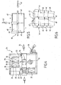
- the Figures 1 to 3 show a device 1 for producing a box 2 from a magazine 3 formed of two piles 4 and 5 of blanks 6 of corrugated sheet material having notches 7.
- the batteries are vertical.
- the device 1 comprises means 8 for locating the top 9 of the stack per camera 10, means for taking off or pre-launching 11, which will be detailed subsequently, of the top cutout 12 of the stack, for example the first stack. 5.
- the device according to the invention further comprises suction means 14 comprising, for example, four or six suction cups 15 for gripping the blank 16.
- the device 1 further comprises a robotic arm 17 for lateral displacement of the cut-out sucked and seized at a subsequent station 17 'for the purpose of forming it, for example at the post after 18.
- the device also comprises sizing means (not shown) of the cutout before the forming station 18 for example around a mandrel 18 '.
- the cutting magazine 3 is formed by a pallet 19, which is for example the pallet which was used for transport, and comprises a lift plate 20 of a type known in itself, which allows the leveling of the pallet 'to a plan of observation and setting 21 (in phantom in the figure).
- a lift plate 20 of a type known in itself, which allows the leveling of the pallet 'to a plan of observation and setting 21 (in phantom in the figure).
- Mechanical or visual detection means of said observation plane of the cut-out of the top for example by means of a limit switch, and / or by means of an infrared ray make it possible to obtain the exact location.
- shaving illumination means 22 are provided and can be used to determine what is the cutout from above. They will be described later.
- All the elements of the device are mounted around a frame 23 in a manner known per se.
- the pallet magazine 25 comprises two piles 26 of rectangular cutouts 27 formed of a bottom 28 and four lateral flaps 29 with indentations 30.
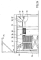
- the electrical cabinet 31 allows the power supply of the assembly and comprises the calculation means (computer, PC, etc.) known in themselves that will be used once properly programmed to perform the desired cycles.
- the robotic arm 32 is arranged to deploy above the magazine 25 and then place on a conveyor belt 33, of known type, the cutout 34, in position to then be guided and taken back (arrow 35) for subsequent forming.
- Gluing means 36 laterally displaceable then deposit the adhesive beads on the package advancing on the treadmill 33.
- a buffer stock 37 of cuts that can be used when the pallet magazine 25 is to be changed, so as not to lose the rate.
- the robotic arm 17 or 32 is for example a commercial robot of the type used in the automotive industry, which allows travel along four intelligent axes.
- the robotic arm takes the cutout in the gripping plane located with the shot plane detector, at the same altitude + 50mm, lifts it, moves it and rests it, in the transfer channel, on the treadmill or to build another stack.
- This last case is used to feed the "classic" store of an existing packaging training machine.
- an observation camera 10 connected to a computer is used.
- This camera gives the robot the position and the angle of the cut with respect to a reference common to the robot and cutting.
- a grazing lighting system illuminating the observation area.
- This lighting system 22 is advantageously oriented to illuminate the cutouts with an angle with respect to the engagement plane 21 between 5 and 25 °, for example 8 °.
- subzones corresponding to the expected edge of the blanks will be defined, namely the zone 1 which will be A1 for A, B1 for B, etc. and the zone 2 which will be perpendicular to zone 1, namely A2 for A, B2 for B, etc.
- the lighting is either fixed lighting (neon or constant light sources) or pulsed lighting (very short flash light pulse).
- a rest point is determined beforehand, ie the point at which the robot must release the zone of vision. This will be the reference point of reference for the positioning movements of the cut.
- the robot 17 or 32 includes a tool for gripping the cutout on the outlet plane provided with suction cups.
- It also includes a calculator arranged to calculate a trajectory that will both allow to take a cut and only one while minimizing the movements of the other cutouts on the shot plane, then that will bring it to the point of installation, it that is to say, as we have seen, either on a channel or in a magazine, or directly on a forming mandrel or in a cavity.
- the shading lights 42, 43 of the figure 5 allow here to generate shadows at the contours 48 and indentations 49 of these cuts that will be used.
- the observation zone may be covered (in a manner not shown) to avoid external light disturbances, which would prevent perfect recognition or identification of the blank with respect to the recorded standard image, as described in FIG. reference to Figures 7A and 7B .
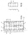
- FIG. 7A shows here an example of a pallet 50 with four stacks 51 of cuts of the type of that described with reference to FIG. figure 6 , lighting (ramp 52) being for example here an illumination, of the pulsed type driven by an image analysis software in a manner known per se.
- the light typically varying and for example from 1 to 150 images per second.
- the lamps are typically positioned at a distance of 5 to 20 cm from the plane to be observed with an angle of incidence between 5 and 30 °.
- Each image is inspected areas A, B, C and D.
- the counters increment 1 to 1.
- Another method that can be used with the process according to the invention consists in determining the sharpest cut corresponding to the standard (cf. Figure 7B ).
- the software then simultaneously manages the two lights and compares the images taken by the camera from two angles, to two corresponding reference images.
- the robot is programmed to guide the operators in the creation of new formats.
- the robot goes into production mode corresponding to the selected format (calibrated format saved).
- the software calculates the presence of the four (or more) shadow zones selected and the distance between these zones.
- the robot moves to match its tool with the mark of the cut, then to take the cut, its trajectory then being perfectly defined.
- the robot is first initialized (block 70), pallet in place, the zone being, for example, the observation zone D.
- the robot is then tested in 71 to know if it is at the point of rest. If it is not there, it is brought there in 72.
- the program starts according to the application chosen in 74, both in terms of speed and number of batteries.
- pulsed lighting it is started in 77 (pulsed asynchronous lighting according to x, y).
- the following pallet X is illuminated (block 78) and an image L is taken, then the following pallet Y is illuminated and an image M. is taken.
- zone zone + 1 is incremented at 79.
- the image L is analyzed as a percentage of image with respect to the reference image area 1, and then the image M as a percentage of image with respect to the reference image area 2.
- test 81 If (test 81) the images L and M coincide with the two reference images, then the center of gravity is calculated (step 82) and the robot is oriented in X, Y and theta.
- the suction cups descend to the point of grip, then the cut is grasped and it is released vertically to allow its movement in X, Y, theta, before actually moving to the point of rest (step 85).
- the cut is deposited at the point of use and the robot returns to the point of rest (step 86).
- zone is then incremented from zone to zone + 1 (step 90), the image L is analyzed (step 91) as a percentage of reference image with respect to zone 1 and zone 2.
- the image L is equal to the reference image (test 92), it is analyzed then its center of gravity and its orientation in X, Y, theta (step 93) are calculated, before catching the previously described procedure in 83 .
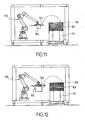
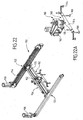
- FIGS. 11 and 12 show two embodiments of the device according to the invention, particularly effective and allowing a rapid formatting of packaging.
- the gripping head being optionally provided with a device (not shown) for folding flaps of the cut around the mandrel.
- flaps may also be folded and pressurized by complementary devices of the type actuated actuator or actuator in a manner known per se.
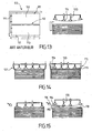
- the pile of cartons is unstacked without disordering by proceeding as follows.
- Plates 114 are positioned on the cutout at different points and one or more sides of the cut are started while blocking the central part thereof (cf. Figures 13 and 14 ).
- Air inlets 115 are thus created by lifting the edges 116 of the cutouts by means of the means (suction cup 114, for example with locking cylinder 120).
- blower nozzles 118 are provided which further prevents the movement of the bottom cut 119 during unstacking as well as for cuts below.
- Advantageously claws 121 may be provided in addition ( figure 14 ) but are not necessary.
- the figure 16 uses a device 120 comprising the suction cups 121 interconnected by a vacuum supply bar 122, said bar comprising, connected in the middle 123, a rod 124 terminated by an end 125 disposed offset from the bar and its suction cups so that it can be positioned laterally above the cutouts 126.
- the figure 18 shows the action of a vibrating jack 130, central pressing the bottom cutout 131 during the rise of the tool 132, the purpose being to create a vibration shock on the cut to take off the cut from below.
- the figure 19 shows another tool according to an embodiment with offset cups 133, 134 connected by a bar 135, in the socket, which reduces the friction surface between two cuts by the natural air intake during the rise of the tooling.
- the figure 20 is another embodiment, simpler than that of the figure 18 , with central punching, for example on a creasing with the vibrating jack 136, the suction cups 137 being hinged at 138 with respect to the gripping arm 139 of the tooling.
- the figure 21 shows yet another embodiment of a tool 140 using blows nozzle 141, from above and suction cups 142 on cylinder.
- It comprises two branches 152 provided with transmission belts 154 for moving a central beam 156 by means of two motors 158, thus allowing the displacement of the central beam in the X, Y axes in the horizontal direction.
- the robot 160 itself comprises a support 162 comprising the branch 164 for supporting the suction cups 166 in a manner known per se, the support being in fact constituted by a movable head 168 connected to a central belt 170 of displacement according to the invention.
- a motor 172 allows the vertical movement Z.
- the figures 23 and 24 show the use of a robot 150 as mentioned in Figures 22 and 22A to form a one-piece case.
- the figure 23 is a schematic top view of the device mounted on a frame 180.
- the robot 160 moves between a gripping portion of the blanks 181 on the vertical magazine 182, and a forming position at the station 183.
- the camera 184 looks at the palette 182 and determines the cut to take in X, Y, theta.
- the cut is then taken by the robot 160 (movement X, Y, Z and rotation along the vertical outer axis) and deposits the cutout on the mandrel 185.
- the formation of the box around the mandrel 185 is then performed by folding down the panels of the belt including via cylinders 187.
- the robot takes the cut in a buffer store (not shown) to avoid interrupting production.
- Raising lights 189 are of course provided as specified above.
- the figure 24 (side view of the device of the figure 23 ), also shows the movement of the robot 160, with application of an ink jet 190 (for writing a bar code for example), the cuts being arranged in a stack on the elevator platform as described above with reference other embodiments.
- an ink jet 190 for writing a bar code for example
Description
La présente invention concerne un procédé pour transfert de découpes pour boîtes d'emballage à section polygonale à partir d'un magasin formé d'au moins une pile de découpes de matière en feuille de carton ou carton ondulé comportant des échancrures.The present invention relates to a method for transferring blanks for polygonal box packaging boxes from a magazine formed of at least one stack of cardboard sheet or corrugated cardboard blanks having indentations.
Elle concerne également un dispositif pour la réalisation d'un tel transfert en vue d'une réalisation de boîte.It also relates to a device for carrying out such a transfer for a box embodiment.
On connaît déjà de nombreux procédés de formation de caisses en carton ondulé.Numerous processes for forming corrugated cardboard boxes are already known.
Ils comportent en général les étapes suivantes :
- Après une prise du flan de carton par ventouse à partir d'un magasin vertical incliné, on encolle le flan ou découpe, puis on le met en volume avant de fermer par rabattement les volets formant le fond et/ou les parois de la boîte ainsi constituée.
- After taking the blank of cardboard by suction from an inclined vertical store, the blank is slotted or cut, then it is placed in volume before closing by folding the shutters forming the bottom and / or the walls of the box and incorporated.
De tels procédés nécessitent le remplissage régulier du magasin.Such methods require regular filling of the magazine.
Pour ce faire le mode de chargement le plus répandu fait appel à l'intervention manuelle d'opérateurs à partir de palettes sur lesquelles les découpes sont empilées.To do this, the most common mode of loading involves the manual intervention of operators from pallets on which the cuts are stacked.
Ce chargement manuel répétitif se révèle cependant très pénible à la longue, surtout lorsque la fréquence de changement des magasins est élevée et que le poids et/ou les dimensions des découpes sont importants.However, this repetitive manual loading proves to be very difficult in the long run, especially when the frequency of change of the magazines is high and the weight and / or dimensions of the cuts are important.
A titre d'exemple, une machine fonctionnant à une cadence de trente caisses par minute pour former des emballages de trois cent grammes, nécessite la manipulation d'environ quatre tonnes de carton par jour (sur huit heures).For example, a machine operating at a rate of thirty cases per minute to form packages of three hundred grams, requires the handling about four tons of cardboard per day (over eight hours).
Une telle manipulation pose des problèmes de santé pour les opérateurs qui expérimentent de ce fait des troubles musculo-squelettiques.Such manipulation poses health problems for operators who experience musculoskeletal disorders as a result.
Il a donc été recherché des solutions permettant le chargement des magasins de façon automatique, sans qu'un opérateur n'ait à soulever de charges de carton.It has therefore been sought solutions for loading the magazines automatically, without an operator having to lift cardboard loads.
On connaît ainsi des systèmes de préhension capables de soulever et déplacer simultanément plusieurs plaques de carton en paquets, ce qui va permettre de transférer une pile entière de cartons d'une palette vers le magasin.Thus known gripping systems capable of simultaneously lifting and moving several sheets of cardboard packets, which will allow to transfer an entire stack of cartons from a pallet to the store.
La difficulté de la mise en oeuvre de tels systèmes réside ici dans la préhension de la pile.The difficulty of implementing such systems resides here in the gripping of the battery.
La prise d'une pile qui se fait par des pinces latérales est en effet difficile à réaliser de façon exacte et répétitive.Taking a stack that is made by side clamps is indeed difficult to achieve accurately and repeatedly.
Classiquement, on utilise des aiguilles insérées entre deux plaques de carton par un côté de la pile à déplacer. L'aiguille soulève légèrement la pile en biais sur le côté et permet alors l'introduction d'une ou plusieurs plaques fines ou pelles sous la pile à soulever. Avec de tels systèmes, la préhension d'un nombre exact de plaques n'est cependant pas garantie.Conventionally, needles inserted between two cardboard plates are used on one side of the stack to be moved. The needle slightly lifts the stack obliquely to the side and then allows the introduction of one or more thin plates or shovels under the pile to be lifted. With such systems, the grip of an exact number of plates is not guaranteed.
On connaît également un dispositif qui comporte des moyens permettant de déplacer latéralement un paquet de découpes sur une pile de façon à la faire émerger de la pile puis à soulever avec une pelle la partie du paquet qui dépasse en introduisant ensuite une plaque en dessous pour déplacer la charge.Also known is a device that includes means for laterally moving a package of cutouts on a stack so as to emerge from the stack and then lift with a shovel the portion of the package that exceeds by then introducing a plate underneath to move load.
En fait les moyens connus permettant d'éviter la fatigue pour les opérateurs consistent essentiellement à traiter les découpes par piles ou par paquets en déplaçant donc un grand nombre de découpes à la fois.In fact, the known means for avoiding fatigue for the operators essentially consist in processing the blanks by stacks or packets, thus moving a large number of blanks at a time.
Document
Une telle solution présente cependant des inconvénients.Such a solution, however, has drawbacks.
Un premier inconvénient, majeur, est de limiter la possibilité de préhension des découpes à des plans de palettisation très simples à savoir en général deux piles de cartons alignées sur une rangée.A first disadvantage, major, is to limit the possibility of gripping cuts to very simple palletizing planes namely in general two stacks of cartons aligned on a row.
En effet il est nécessaire que deux bords opposés des découpes soient accessibles pour que celles-ci puissent être prises avec des pinces.Indeed it is necessary that two opposite edges of the cuts are accessible so that they can be taken with clamps.
Les dispositifs de l'art antérieur ne permettent donc pas de dépiler des palettes comportant plusieurs rangées de découpes, chaque rangée comportant elle-même plusieurs piles.The devices of the prior art therefore do not allow to unstack pallets with several rows of cuts, each row itself having several stacks.
Or, de telles palettes, qui permettent d'optimiser les coûts de transports, sont de plus en plus souvent utilisées.Such pallets, which make it possible to optimize transport costs, are more and more often used.
De tels dispositifs ne conviennent pas non plus si les formes des découpes permettent leur imbrication sur les palettes.Such devices are not suitable either if the shapes of the cuts allow their nesting on the pallets.
Un autre inconvénient réside dans l'impossibilité d'atteindre les découpes situées tout en bas de la palette, impossibles à extraire automatiquement. Elles sont donc souvent perdues ce qui génère un déchet important.Another disadvantage lies in the impossibility of reaching the cuts located at the bottom of the pallet, impossible to extract automatically. They are therefore often lost which generates a significant waste.
Enfin si les palettes ont été secouées pendant les manipulations qui précèdent leur positionnement en zone de dépilage, les découpes d'une même palette vont s'être déplacées et vont souvent s'être imbriquées les unes entre les autres.Finally, if the pallets were shaken during the manipulations that precede their positioning in the unstacking zone, the cuts of the same pallet will have moved and will often be nested between each other.
Ce phénomène rend alors le dépilage difficile et génère des arrêts de machines avec intervention humaine pour recadrer les découpes sur la palette empêchant une réelle automatisation du processus.This phenomenon makes unstacking difficult and generates machine stops with human intervention to crop the cuts on the pallet preventing real automation of the process.
La présente invention vise à pallier ces inconvénients, en proposant un procédé et un dispositif répondant mieux que ceux antérieurement connus aux exigences de la pratique, notamment en ce qu'elle autorise la dépalettisation de découpes à grandes cadences quel que soit le plan de palettisation.The present invention aims to overcome these disadvantages, by providing a method and a device that better than those previously known to the requirements of the practice, in particular in that it allows the depalletization of cuts at high rates regardless of the palletizing plan.
L'invention trouve une application particulièrement importante bien que non exclusive dans le domaine de la formation de boîtes à partir de découpes ou plaques en carton ondulé de faible grammage (<120g/m2) pour l'industrie ou l'agro-alimentaire.The invention finds a particularly important application although not exclusive in the field of the formation of boxes from blanks or sheets of corrugated cardboard of low basis weight (<120g / m2) for the industry or the food industry.
Avec l'invention il va être possible d'effectuer automatiquement le dépilage même si les découpes se sont déplacées latéralement, ont pivotées, se sont imbriquées, ou se chevauchent.With the invention it will be possible to perform unstacking automatically even if the cuts have moved laterally, rotated, nested, or overlapped.
En proposant une prise unitaire de chaque découpe elle permet de plus une mise en volume optionnelle après encollage de ladite découpe par le même outil, l'inscription d'un code barre par ancrage et/ou la fixation d'une puce RFID ou de tout autre moyen de repérage, pouvant également s'effectuer en même temps et dans la continuité du mouvement.By proposing a unitary catch of each cutout it also allows an optional setting volume after gluing of said cut by the same tool, the registration of a bar code by anchoring and / or fixing an RFID chip or any another means of identification, which can also be done at the same time and in the continuity of the movement.
Elle permet également d'accéder à toutes les découpes des palettes sans perte des dernières découpes.It also allows access to all cutouts of the pallets without loss of the last cuts.
Pour ce faire l'invention part notamment de l'idée de ne plus déplacer des paquets de plaques vers un magasin d'alimentation en général incliné, mais de traiter les découpes une à une après les avoir parfaitement localisées dans l'espace et repositionnées pendant le mouvement.To do this, the invention notably starts from the idea of no longer moving plate packs to a feed store in general inclined, but to treat the cuts one by one after having perfectly located them in space and repositioned during movement.
Dans ce but la présente invention propose essentiellement un procédé de transfert de découpe pour la réalisation de boîtes d'emballage à section polygonale à partir d'un magasin formé d'au moins une pile de découpes de matière en feuille de carton ou carton ondulé comportant des échancrures, caractérisé en ce que
la pile étant verticale, on localise la découpe du dessus de la pile par caméra,
on pré-décolle ladite découpe du reste de la pile,
on saisit la découpe du dessus ainsi localisée par aspiration,
on déplace ladite découpe à l'aide d'un bras robotisé et on la libère à un poste suivant, pour ou avant formage ultérieur,
et on renouvelle le cycle d'étapes ci-dessus avec la découpe de dessus suivante.For this purpose, the present invention essentially proposes a method for transferring cutting for the production of polygonal box packaging boxes from a magazine formed of at least one stack of blanks made of cardboard or corrugated cardboard material comprising notches, characterized in that
the stack being vertical, the cutout of the top of the stack is located by camera,
pre-cutting said cutout from the rest of the stack,
we enter the cut of the top thus localized by aspiration,
said cut is moved by means of a robotic arm and released to a next station, for or before further forming,
and the above cycle of steps is repeated with the next overhead cut.
Avec le procédé selon l'invention, il est donc possible de réaliser la prise unitaire d'une découpe par aspiration c'est à dire par ventouse à partir d'une palette comportant plusieurs piles et/ou plusieurs rangées avec ou sans imbrication de découpes.With the method according to the invention, it is therefore possible to perform the unitary taking of a cut by suction, that is to say by sucking from a pallet comprising several stacks and / or several rows with or without nesting cutouts. .
La cadence de manipulation des découpes est par ailleurs multipliée par un facteur de dix à cinquante par rapport à une manipulation de paquets, et ce malgré la difficulté de déplacer à grande vitesse dans l'espace des plaques de carton qui se comportent comme des ailes déformables.The cutting handling rate is also multiplied by a factor of ten to fifty compared to a package handling, despite the difficulty of moving at high speed in the space of cardboard plates that behave like deformable wings.
Le soulèvement rapide d'une plaque de carton à partir d'une pile n'a par ailleurs jamais été recherché dans l'art antérieur car il génère un phénomène d'aspiration entre la plaque soulevée et les plaques situées en dessous.The rapid lifting of a cardboard plate from a stack has also never been sought in the prior art because it generates a phenomenon of suction between the raised plate and the plates below.
Il en résulte que plusieurs des plaques situées sous la plaque soulevée changent de position latéralement et en rotation de façon totalement aléatoire à chaque prise.As a result, many of the plates beneath the raised plate change position laterally and rotationally in a totally random manner with each tap.
Elles peuvent alors surchapper les découpes de la pile adjacente et l'homme du métier aurait trouvé trop difficile de les repérer dans l'espace et de les repositionner avec certitude à un endroit déporté.They can then escape the cuts of the adjacent stack and the skilled person would have found too difficult to locate them in space and reposition them with certainty at a remote location.
En prédécollant les découpes et en les localisant précisément par caméra on pallie à cet inconvénient.By pre-cutting the cutouts and locating them precisely by camera, this disadvantage is overcome.
Dans des modes de réalisation avantageux, on a de plus recours à l'une et/ou à l'autre des dispositions suivantes :
- on encolle ladite découpe avant le poste suivant qui est un poste de formage ;
- le procédé comporte plus de trente cycles par minutes ;
- le magasin comporte plusieurs rangées et/ou plusieurs piles de découpes à partir desquels la découpe du dessus est saisie ;
- on utilise plusieurs bras robotisés travaillant en alternance ;
- le magasin de découpes étant formé par une palette,
on fait monter le dessus de la palette jusqu'à un plan d'observation et de prise,
on détecte la découpe du dessus,
et on saisit par aspiration ladite découpe pour l'amener au poste suivant ;
- on détecte la découpe du dessus avec au moins une caméra numérique située au dessus du magasin et centrée par rapport audit magasin,
et on transmet à un calculateur les données ainsi obtenues pour déterminer la découpe du dessus ;
- on éclaire de façon rasante les découpes du dessus pour générer des ombres du fait des échancrures et des surchappements entre découpes et on écarte les découpes qui n'ont pas toutes leur zones d'ombre comme étant en dessous ;
- on détermine la découpe la plus nette dans le plan de prise pour localiser la découpe du dessus ;
- à partir des mesures des découpes à localiser dans le plan de prise et de l'image obtenue par la ou les caméras,
on communique le résultat de ces calculs au bras robotisé muni de l'outillage d'aspiration et on déplace ledit robot pour faire coïncider ledit outillage d'aspiration avec le repère de la découpe avant de la saisir par aspiration avec le dit appareillage ;
- pour effectuer le pré-décollage et saisir la découpe du dessus par aspiration on vient positionner les ventouses sur la découpe en différents points, puis on commence à soulever un ou plusieurs cotés de la découpe tout en bloquant une partie de la découpe, pour créer au moins une entrée d'air latéral ;
- le formage se fait par pistonnement dans une cavité ;
- on forme la boîte au poste de formage par enroulement des découpes autour d'un volume déterminé ;
- on amène la découpe du dessus au poste de formage par ventouses aspirantes déplacées selon l'axe horizontal par le bras robotisé à une vitesse de translation comprise entre 4m/s et 6m/s ;
- on transfère la découpe au poste de formage par un équipage de deux chariots sur lequel est monté le bras robotisé, ledit équipage étant actionné par un système d'entraînement comprenant un agencement de poulie et de courroie avec moteur électriques ;
- on forme la boîte à partir d'une découpe comportant une suite d'au moins quatre volets principaux terminée par une languette de fixation, reliés entre eux par des premières lignes de pliage parallèles entre elles, ladite suite de volets formant les parois externes de la boîte et étant reliée d'un coté à une suite de rabats par des deuxièmes lignes de pliage perpendiculaires aux dites premières lignes de pliage, pour former le fond de la boîte ;
- on forme la boîte à partir d'une découpe comportant un panneau central et quatre rabats périphériques latéraux ;
- le procédé comporte une étape de marquage après préhension par le robot et avant dépose au poste suivant.
- said cut is glued before the next station which is a forming station;
- the process comprises more than thirty cycles per minute;
- the magazine comprises several rows and / or several stacks of cuts from which the top cut is captured;
- we use several robotic arms working alternately;
- the cutout magazine being formed by a pallet,
the top of the pallet is raised to an observation and setting plane,
the cutout of the top is detected,
and said suction is grasped by suction to bring it to the next station;
- the cutout of the top is detected with at least one digital camera located above the store and centered with respect to said store,
and transmitting to a computer the data thus obtained to determine the cut of the top;
- the cut-outs of the top are shaved in a grainy way to generate shadows because of the indentations and escapes between cut-outs, and the cut-outs which do not all have their shadows as below are separated;
- the sharpest cut in the shot plane is determined to locate the cutout of the top;
- from measurements of the cuts to be located in the shot plane and the image obtained by the camera or cameras,
the result of these calculations is communicated to the robotic arm equipped with the suction tooling and said robot is moved to make said suction tool coincide with the mark of the cutout before grasping it by suction with said apparatus;
- to perform the pre-takeoff and grab the top cut by suction we just position the suction cups on the cutout at different points, then one begins to lift one or more sides of the cut while blocking part of the cut, to create at least one side air inlet;
- the forming is done by piston in a cavity;
- the box is formed at the forming station by winding the blanks around a determined volume;
- the top blank is fed to the suction cup forming station displaced along the horizontal axis by the robotic arm at a translation speed of between 4m / s and 6m / s;
- transferring the blank to the forming station by a crew of two trolleys on which is mounted the robotic arm, said crew being actuated by a drive system comprising a pulley and belt arrangement with electric motors;
- the box is formed from a cutout comprising a sequence of at least four main shutters terminated by a fastening tab, interconnected by first fold lines parallel to each other, said sequence of shutters forming the outer walls of the box and being connected on one side to a series of flaps by second fold lines perpendicular to said first fold lines, to form the bottom of the box;
- forming the box from a cutout comprising a central panel and four lateral peripheral flaps;
- the method comprises a marking step after gripping by the robot and before removal to the next station.
L'invention propose de plus un dispositif mettant en oeuvre le procédé tel que décrit ci-dessus.The invention further provides a device implementing the method as described above.
L'invention concerne également un dispositif pour la réalisation de boîtes d'emballage à section polygonale à partir d'un magasin formé d'au moins une pile de découpes de matière en feuille de carton ou carton ondulé comportant des échancrures, caractérisé en ce que, la pile étant verticale, il comporte
des moyens de localisation de la découpe du dessus de la pile par caméra,
des moyens de décollage de ladite découpe par rapport au reste de la pile,
des moyens de saisie de ladite découpe par aspiration comprenant un jeu d'au moins quatre ventouses, et
un bras robotisé de déplacement latéral de ladite découpe à un poste suivant, en vue de son formage, avant retour à vide pour saisir la découpe de dessus suivante.The invention also relates to a device for producing polygonal section packaging boxes from a magazine formed of at least one stack of blanks made of corrugated cardboard or corrugated cardboard material, characterized in that , the pile being vertical, it comprises
means for locating the cutting of the top of the stack by camera,
means for taking off said cut with respect to the rest of the stack,
means for gripping said suction cut-out comprising a set of at least four suckers, and
a robotic arm for lateral displacement of said blank at a next station, for the purpose of forming it, before empty return to capture the next top blank.
Dans des modes de réalisation avantageux, on a de plus recours à l'une et/ou à l'autre des dispositions suivantes :
- le dispositif comporte de plus des moyens d'encollage de ladite découpe avant le poste suivant ;
- le magasin comporte plusieurs rangées et/ou plusieurs piles de découpes à partir desquels la découpe du dessus est saisie ;
- il comporte plusieurs bras robotisés travaillant en alternance ;
- le magasin de découpes étant formé par une palette,
des moyens de détection visuelle dudit plan d'observation;
- le dispositif comprend au moins une caméra numérique située au dessus du magasin et centrée par rapport audit magasin,
des moyens de calcul à partir des données ainsi obtenues pour déterminer la découpe du dessus ;
- il comporte des moyens d'éclairage de façon rasante des découpes du dessus pour générer des ombres du fait des échancrures et/ou des surchappements entre découpes et des moyens de sélection de la découpe pertinente agencés pour écarter les découpes qui n'ont pas toutes leur zones d'ombre comme étant en dessous. Par éclairage de façon rasante, on entent horizontalement ou avec un angle par rapport au plan de la découpe inférieur à 30 °,
par exemple 15 °; - il comporte des moyens de sélection de la découpe la plus nette dans le plan de prise pour localiser la découpe du dessus ;
- le dispositif comprend
des moyens de calcul de la présence des quatre ou plus zones d'ombre et la distance entre ces zones,
des moyens de calcul du barycentre et de l'angle de la découpe par rapport à une position de référence, des moyens de transmission du résultat de ces calculs au bras robotisé muni de l'outillage d'aspiration et
de moyens pour faire coïncider ledit outillage d'aspiration avec le repère de la découpe avant de la saisir par aspiration avec le dit appareillage;
- les moyens pour décoller la découpe du dessus comprennent des élément agencés pour soulever un ou plusieurs cotés de la découpe tout en bloquant une partie de la découpe, pour créer au moins une entrée d'air latéral ;
- le dispositif comporte un poste de formage par pistonnement dans une cavité ;
- il comporte un poste de formage par enroulement des découpes autour d'un volume déterminé ;
- il comporte un équipage de deux chariots sur lequel est monté le bras robotisé, ledit équipage étant actionné par un système d'entraînement comprenant un agencement de poulie et de courroie avec moteur électriques.
- the device further comprises means for gluing said cutout before the next station;
- the magazine comprises several rows and / or several stacks of cuts from which the top cut is captured;
- it has several robotic arms working alternately;
- the cutout magazine being formed by a pallet,
visual detection means of said observation plane;
- the device comprises at least one digital camera located above the store and centered with respect to said store,
calculating means from the data thus obtained for determining the cutting of the top;
- it comprises grazing means for shaving the cutouts from above to generate shadows because of notches and / or escapes between cutouts and means for selecting the relevant cutout arranged to separate cutouts that do not all have their own shape. shadow areas as being below. By grazing light, enter horizontally or with an angle relative to the plane of the cut below 30 °, for example 15 °;
- it comprises means for selecting the sharpest cut in the shot plane to locate the cutout of the top;
- the device includes
means for calculating the presence of the four or more shadow zones and the distance between these zones,
means for calculating the barycentre and the angle of the cut relative to a reference position, means for transmitting the result of these calculations to the robotic arm equipped with the suction tool and
means for aligning said suction tooling with the mark of the cutout before grasping it by suction with said apparatus;
- the means for taking off the top cutout comprise elements arranged to lift one or more sides of the cut while blocking part of the cut, to create at least one lateral air inlet;
- the device comprises a booster forming station in a cavity;
- it comprises a forming station by winding the blanks around a determined volume;
- it comprises a crew of two trolleys on which is mounted the robotic arm, said crew being actuated by a drive system comprising a pulley and belt arrangement with electric motors.
L'invention sera mieux comprise à la lecture de la description qui suit de modes de réalisation donnés ci-après à titre d'exemples non limitatifs.The invention will be better understood on reading the following description of embodiments given below by way of non-limiting examples.
Elle se réfère aux dessins qui l'accompagnent dans lesquels :
- La
figure 1 est une vue schématique en élévation de face d'un dispositif selon un premier mode de réalisation de l'invention. - La
figure 2 est la vue en élévation latérale du dispositif de lafigure 1 . - La
figure 3 est une vue de dessus du dispositif de lafigure 1 . - La
figure 4 est une vue de dessus d'un autre mode de réalisation d'un dispositif selon l'invention. - La
figure 5 est un schéma montrant le procédé de repérage par caméra en vue de dessus. - La
figure 6 est un exemple en vue de dessus de découpes en vrac et décalées, saisissables grâce au procédé selon l'invention. - La
figure 7A montre en vue de dessus un exemple de palette à quatre piles légèrement décalées. - La
figure 7B illustre l'étalonnage de la caméra qui permet ensuite le repérage des découpes telles que représentées sur lafigure 7A . - Les
figure 8 et 9 illustrent les zones d'ombre sur découpes avec éclairages latéraux, utilisables avec les caméras et les logiciels de calcul selon l'invention. - La
figure 10 donne un organigramme du fonctionnement d'un mode de réalisation du procédé selon l'invention. - Les
figures 11 et 12 montrent en vue latérale un dispositif selon l'invention appliqué au formage autour d'un mandrin (figure 11 ) et par pistonnement dans une cavité (figure 12 ). - Les
figures 13 à 16 montrent des modes de réalisation du pré-décollage de la découpe saisie avant aspiration. - La
figure 17 est un exemple de réalisation d'un outillage d'aspiration utilisable avec l'invention avec moyens de pré-décollage. - Les
figures 18 à 21 montrent d'autres modes de réalisation de pré-décollage de la découpe avant saisie par aspiration. - Les
figures 22 et 22A montrent un autre mode de réalisation d'un robot et/ou bras robotisé utilisable avec un dispositif selon l'invention. - La
figure 23 est une vue de dessus d'un dispositif selon l'invention utilisant un robot du type décrit en référence à lafigure 22 . - La
figure 24 est une vue latérale schématique du dispositif de lafigure 23 .
- The
figure 1 is a schematic view in front elevation of a device according to a first embodiment of the invention. - The
figure 2 is the side elevation view of the device from thefigure 1 . - The
figure 3 is a top view of the device of thefigure 1 . - The
figure 4 is a top view of another embodiment of a device according to the invention. - The
figure 5 is a diagram showing the camera tracking method in top view. - The
figure 6 is an example in top view of loose cutouts and staggered, enterable by the method according to the invention. - The
Figure 7A shows in top view an example of a pallet with four slightly offset stacks. - The
Figure 7B illustrates the calibration of the camera which then allows the identification of the cutouts as represented on theFigure 7A . - The
figure 8 and 9 illustrate the shadow areas on cutouts with side lights, used with the cameras and calculation software according to the invention. - The
figure 10 gives a flowchart of the operation of an embodiment of the method according to the invention. - The
Figures 11 and 12 show in side view a device according to the invention applied to forming around a mandrel (figure 11 ) and by pumping into a cavity (figure 12 ). - The
Figures 13 to 16 show embodiments of pre-take off of the cut before suction. - The
figure 17 is an embodiment of an aspiration tooling that can be used with the invention with pre-takeoff means. - The
Figures 18 to 21 show other embodiments of pre-takeoff of the cut before suction capture. - The
Figures 22 and 22A show another embodiment of a robot and / or robotic arm that can be used with a device according to the invention. - The
figure 23 is a top view of a device according to the invention using a robot of the type described with reference to thefigure 22 . - The
figure 24 is a schematic side view of the device of thefigure 23 .
Dans la suite de la description on utilisera dans la mesure du possible les mêmes numéros de référence pour désigner des éléments identiques.In the remainder of the description, the same reference numbers will be used as far as possible to designate identical elements.
Les
Les piles sont verticales. Le dispositif 1 comporte des moyens 8 de localisation du dessus 9 de la pile par caméra 10, des moyens de décollage ou pré-décollage 11, qui seront détaillés par la suite, de la découpe de dessus 12 de la pile par exemple la première pile 5.The batteries are vertical. The device 1 comprises means 8 for locating the top 9 of the stack per camera 10, means for taking off or
Le dispositif selon l'invention comprend de plus des moyens 14 d'aspiration comprenant par exemple quatre ou six ventouses 15 de saisie de la découpe 16.The device according to the invention further comprises suction means 14 comprising, for example, four or six
Le dispositif 1 comprend de plus un bras robotisé 17 de déplacement latéral de la découpe aspirée et saisie à un poste suivant 17' en vue de son formage par exemple au poste d'après en 18.The device 1 further comprises a
Le dispositif comporte également des moyens d'encollage (non représentés) de la découpe avant le poste de formage 18 par exemple autour d'un mandrin 18'.The device also comprises sizing means (not shown) of the cutout before the forming
Plus précisément le magasin de découpe 3 est formé par une palette 19, qui est par exemple la palette qui a servi au transport, et comporte un plateau élévateur 20 de type connu en lui-même, qui permet la mise à niveau de la palette jusqu'à un plan d'observation et de prise 21 (en traits mixtes sur la figure). Des moyens de détection mécanique ou visuelle dudit plan d'observation de la découpe du dessus (non représentés), par exemple par l'intermédiaire d'un fin de course, et/ou par le biais d'un rayon infrarouge permettent d'obtenir l'emplacement exact.More specifically, the cutting
Selon le mode de réalisation de l'invention plus particulièrement décrit ici, des moyens 22 d'éclairage rasant sont prévus et vont pouvoir être utilisés de façon à déterminer quelle est la découpe du dessus. Ils seront décrits plus avant par la suite.According to the embodiment of the invention more particularly described here, shaving illumination means 22 are provided and can be used to determine what is the cutout from above. They will be described later.
L'ensemble des éléments du dispositif sont montés autour d'un châssis 23 de façon connue en elle-même.All the elements of the device are mounted around a
Des moyens d'alimentation (non représentés) automatique et de mise au vide des ventouses sont par ailleurs bien entendu prévus de façon connue en elle-même.Automatic supply means (not shown) and vacuum suction cups are also provided of course in a known manner in itself.
On a représenté sur la
L'armoire électrique 31 permet l'alimentation électrique de l'ensemble et comporte les moyens de calculs (ordinateur, PC, etc) connus en eux-mêmes qui vont être utilisés une fois correctement programmés pour effectuer les cycles recherchés. Le bras robotisé 32 est agencé pour se déployer au dessus de magasin 25 puis venir placer sur un tapis roulant 33, de type connu, la découpe 34, en position pour ensuite être guidée et reprise (flèche 35) pour formage ultérieur.The
Des moyens encolleurs 36 déplaçables latéralement viennent alors déposer les cordons de colle sur l'emballage avançant sur le tapis roulant 33.Gluing means 36 laterally displaceable then deposit the adhesive beads on the package advancing on the
Il peut par exemple être prévu un stock tampon 37 de découpes utilisable lorsque le magasin palette 25 doit être changé, et ce de façon à ne pas perdre la cadence.For example, it can be provided a
Le bras robotisé 17 ou 32 est par exemple un robot du commerce du type utilisé dans l'industrie automobile, qui permet les déplacements selon quatre axes intelligents.The
Il est capable de positionner la découpe 34 par rapport à des coordonnées fournies par le logiciel dont le fonctionnement sera décrit plus précisément en référence à la
Pour ce faire, le bras robotisé prend la découpe dans le plan de prise situé grâce au détecteur de plan de prise, à une même altitude + 50mm, la soulève, la déplace et la repose, dans le chenal de transfert, sur le tapis roulant ou pour constituer une autre pile.To do this, the robotic arm takes the cutout in the gripping plane located with the shot plane detector, at the same altitude + 50mm, lifts it, moves it and rests it, in the transfer channel, on the treadmill or to build another stack.
Ce dernier cas permet d'alimenter le magasin « classique » d'une machine de formation d'emballage existante.This last case is used to feed the "classic" store of an existing packaging training machine.
Dans le cas où l'on veut augmenter la cadence, on pourra équiper le dispositif de plusieurs bras robot travaillant en alternance et se complétant.In the case where we want to increase the rate, we can equip the device with several robot arms working alternately and complementing each other.
Selon l'invention il est donc utilisée une caméra d'observation 10 liée à un calculateur.According to the invention, an observation camera 10 connected to a computer is used.
Cette caméra donne au robot la position et l'angle de la découpe par rapport à un repère commun au robot et à la découpe.This camera gives the robot the position and the angle of the cut with respect to a reference common to the robot and cutting.
Dans un mode de réalisation avantageux de l'invention, pour permettre une bonne précision et une insensibilité lumineuse aux perturbations, il est prévu un système d'éclairage rasant éclairant la zone d'observation.In an advantageous embodiment of the invention, to provide good accuracy and insensitivity to light disturbances, there is provided a grazing lighting system illuminating the observation area.
Ce système d'éclairage 22 est avantageusement orienté pour éclairer les découpes avec un angle par rapport au plan de prise 21 compris entre 5 et 25°, par exemple 8°.This
Un tel éclairage crée ainsi des ombres qui vont générer des contrastes permettant l'appréciation de la position de la découpe par rapport au reste de la pile sans risque d'erreur.Such lighting thus creates shadows that will generate contrasts allowing appreciation of the position of the cut relative to the rest of the stack without risk of error.
On a représenté sur la
Dans ces zones incrémentables on va définir des sous zones correspondant au bord attendu des découpes, à savoir la zone 1 qui va être A1 pour A, B1 pour B, etc... et la zone 2 qui elle, va être perpendiculaire à la zone 1, à savoir A2 pour A, B2 pour B, etc ..In these incremental zones subzones corresponding to the expected edge of the blanks will be defined, namely the zone 1 which will be A1 for A, B1 for B, etc. and the zone 2 which will be perpendicular to zone 1, namely A2 for A, B2 for B, etc.
On utilise ensuite pour créer les zones d'ombre dans ces zones A1, A2, ... des éclairages forcés latéraux suivant X (flèche 42) ou suivant Y (flèche 43).Then we use to create the shaded areas in these zones A1, A2, ... forced side lights along X (arrow 42) or following Y (arrow 43).
L'éclairage est soit un éclairage fixe (néon ou sources lumineuses constantes), soit un éclairage pulsé (pulsion lumineuse de temps très court du type flash).The lighting is either fixed lighting (neon or constant light sources) or pulsed lighting (very short flash light pulse).
Enfin et avant la mise en route on détermine au préalable un point de repos, c'est à dire le point où le robot doit libérer la zone de vision. Ce sera le point de passage de référence pour les déplacements de localisation de la découpe.Lastly, before start-up, a rest point is determined beforehand, ie the point at which the robot must release the zone of vision. This will be the reference point of reference for the positioning movements of the cut.
Le robot 17 ou 32 comprend un outillage de préhension de la découpe sur le plan de prise muni de ventouses.The
Il comprend également un calculateur agencé pour calculer une trajectoire qui va à la fois permettre de prendre une découpe et une seule tout en minimisant les déplacements des autres découpes sur le plan de prise, puis qui va l'amener au point de pose, c'est à dire, comme on l'a vu, soit sur un chenal, soit dans un magasin, soit directement sur un mandrin de formage ou dans une cavité.It also includes a calculator arranged to calculate a trajectory that will both allow to take a cut and only one while minimizing the movements of the other cutouts on the shot plane, then that will bring it to the point of installation, it that is to say, as we have seen, either on a channel or in a magazine, or directly on a forming mandrel or in a cavity.
On a représenté sur la
Les éclairages rasant 42, 43 de la
A ce sujet et avantageusement, la zone d'observation peut être capotée (de façon non représentée) pour éviter les perturbations lumineuses extérieures, qui empêcheraient une reconnaissance ou une identification parfaite de la découpe par rapport à l'image étalon enregistrée, comme décrit en référence aux
La
Ceci permet à la lumière (néon ou LEDS) de n'être activée que lors d'une prise d'images, la pulsation variant typiquement et par exemple de 1 à 150 images par seconde.This allows the light (neon or LEDS) to be activated only during an image taking, the pulse typically varying and for example from 1 to 150 images per second.
Les lampes sont quant-à-elles typiquement positionnées à une distance de 5 à 20 cm par rapport au plan à observer avec un angle d'incidence compris entre 5 et 30°.The lamps are typically positioned at a distance of 5 to 20 cm from the plane to be observed with an angle of incidence between 5 and 30 °.
Sur l'exemple de la
Ce n'est que si A se découvre, par le retrait de B que le système prendra A.Only if A finds out, by the withdrawal of B that the system will take A.
Une identification précise des coordonnées d'une découpe de référence a été au préalable établie par rapport à une image étalon pré-enregistrée grâce au positionnement précis d'une découpe témoin 55 (
En créant des zones d'ombre on trouve le barycentre et l'angle de rotation de la découpe.By creating shadow areas we find the center of gravity and the angle of rotation of the cut.
La rapidité de calcul pour trouver la position (x, y) et l'angle (θ) du barycentre 58 (voir
Pour une découpe donnée un temps déterminé maximum va exister pour sa localisation, avec une répétabilité dans son positionnement inférieure à 1mm. Pour deux découpes le temps sera inférieur au temps d'une découpe multiplié par deux, etc.For a given cut a given maximum time will exist for its location, with a repeatability in its positioning less than 1mm. For two cuts the time will be less than the time of a cut multiplied by two, etc.
Si le temps de localisation d'une découpe sort de la tolérance de contrôle elle est considérée comme non conforme.If the localization time of a cutout is outside the control tolerance, it is considered as non-compliant.
C'est donc sur ce principe que le chevauchement entre les découpes va être traité. Anis la découpe 53 sur la
A chaque prise d'image on inspecte donc les zones A, B, C et D.Each image is inspected areas A, B, C and D.
Tant qu'il n'y a pas de recouvrement, les compteurs s'incrémentent 1 à 1.As long as there is no overlap, the counters increment 1 to 1.
Si la découpe suivante est recouverte, alors on prend celle qui suit (si est elle conforme) et ainsi de suite.If the next cut is covered, then we take the following one (if it is consistent) and so on.
Une autre méthode, utilisable avec le procédé selon l'invention consiste à déterminer la découpe la plus nette correspondant à l'étalon (cf.
Plus l'algorithme de mesure est complexe plus la puissance de calcul doit être importante pour traiter l'image. Avec des plans de palétisation complexes, des systèmes d'éclairage désynchronisés entre eux de façon à permettre un traitement adéquats sont par exemple également prévus.The more complex the measurement algorithm, the greater the computational power needed to process the image. With complex palletization plans, lighting systems desynchronized together to allow adequate treatment are for example also provided.
On a représenté sur les
Le logiciel gère alors simultanément les deux éclairages et compare les images prises par la caméra sous deux angles, à deux images de référence correspondantes.The software then simultaneously manages the two lights and compares the images taken by the camera from two angles, to two corresponding reference images.
Dans des cas simples on peut par contre se limiter à un éclairage et à une image de référence, comme décrit ci-avant.In simple cases, however, it may be limited to lighting and a reference image, as described above.
De façon connue en elle-même, le robot est programmé pour guider les opérateurs dans la création de nouveaux formats.In a manner known in itself, the robot is programmed to guide the operators in the creation of new formats.
Une fois celle-ci réalisée, le robot passe en mode production correspondant au format sélectionné (format étalonné enregistré).Once this is done, the robot goes into production mode corresponding to the selected format (calibrated format saved).
Pour l'apprentissage d'un format, on effectue les mesures des découpes à localiser sur un plan de palétisation.To learn a format, measurements are made of the cuts to be located on a palettization plan.
A partir de l'image reçue le logiciel calcule la présence des quatre (ou plus) zones d'ombre retenues et la distance entre ces zones.From the image received, the software calculates the presence of the four (or more) shadow zones selected and the distance between these zones.
Il calcule ensuite les coordonnées du barycentre (x, y) et de l'angle (θ) de la découpe, et communique au robot le repère de cette dernière.It then calculates the coordinates of the barycentre (x, y) and the angle (θ) of the cut, and communicates to the robot the reference of the latter.
Puis le robot se déplace pour faire coïncider son outillage avec le repère de la découpe, puis pour prendre la découpe, sa trajectoire étant alors parfaitement définie.Then the robot moves to match its tool with the mark of the cut, then to take the cut, its trajectory then being perfectly defined.
On va maintenant décrire en référence à la
Le robot est tout d'abord initialisé (bloc 70), palette en place, la zone étant par exemple la zone d'observation D.The robot is first initialized (block 70), pallet in place, the zone being, for example, the observation zone D.
Le robot est ensuite testé en 71 pour savoir s'il est au point repos. S'il n'y est pas on l'y amène en 72.The robot is then tested in 71 to know if it is at the point of rest. If it is not there, it is brought there in 72.
Ensuite l'opérateur demande en 73 si un cycle doit être effectué.Then the operator asks at 73 whether a cycle should be performed.
Si oui, le programme commence selon l'application choisie en 74, tant au niveau cadence que nombre de piles.If so, the program starts according to the application chosen in 74, both in terms of speed and number of batteries.
Là, deux modes de réalisation sont par exemple envisageables, à savoir celui utilisant des éclairages pulsés (colonne 75), ou celui utilisant un éclairage forcé mais normal (colonne 76).There, for example, two embodiments can be envisaged, namely that using pulsed lighting (column 75), or that using forced but normal lighting (column 76).
Plus précisément, dans le cas d'un éclairage pulsé, on démarre celui-ci en 77 (éclairage pulsé asynchrone suivant x,y).More precisely, in the case of pulsed lighting, it is started in 77 (pulsed asynchronous lighting according to x, y).
On éclaire alors (bloc 78) la palette suivant X et on prend une image L, puis on éclaire la palette suivant Y et on prend une image M.The following pallet X is illuminated (block 78) and an image L is taken, then the following pallet Y is illuminated and an image M. is taken.
On incrémente en 79 la zone (D → A → B → C) i.e. zone = zone + 1.The zone (D → A → B → C) i.e. zone = zone + 1 is incremented at 79.
En 80, on analyse l'image L en pourcentage d'image par rapport à l'image de référence zone 1, puis l'image M en pourcentage d'image par rapport à l'image de référence zone 2.At 80, the image L is analyzed as a percentage of image with respect to the reference image area 1, and then the image M as a percentage of image with respect to the reference image area 2.
Si (test 81) les images L et M coïncident avec les deux images de référence, alors on calcule le barycentre (étape 82) et on oriente le robot en X, Y et theta.If (test 81) the images L and M coincide with the two reference images, then the center of gravity is calculated (step 82) and the robot is oriented in X, Y and theta.
On communique les coordonnées X, Y, theta au robot qui se déplace aux points X, Y, θ situé au dessus de la découpe, c'est à dire avec une coordonnée verticale en Z au dessus de l'axe. Z de prise (bloc 84).We communicate the coordinates X, Y, theta to the robot that moves at the points X, Y, θ located above the cut, ie with a vertical coordinate in Z above the axis. Z taken (block 84).
Les ventouses descendent au point de prise, puis la découpe est saisie et on la dégage verticalement pour permettre son déplacements en X, Y, theta, avant de la déplacer effectivement au point repos (étape 85).The suction cups descend to the point of grip, then the cut is grasped and it is released vertically to allow its movement in X, Y, theta, before actually moving to the point of rest (step 85).
La découpe est déposée au point d'utilisation et le robot retourne au point repos (étape 86).The cut is deposited at the point of use and the robot returns to the point of rest (step 86).
La suite d'étapes 84 à 86 est ensuite renouvelée avec la découpe d'après (requête d'un cycle complémentaire en 87).The sequence of
L'autre mode de réalisation du fonctionnement du procédé décrit en référence à la
Après démarrage de l'éclairage forcé mais normal en 88 de la palette, on prend en 89 une image avec la caméra.After starting the forced but normal lighting in 88 of the palette, we take in 89 an image with the camera.
On incrémente ensuite la zone, de zone en zone + 1 (étape 90), on analyse (étape 91) l'image L en pourcentage d'image de référence par rapport à la zone 1 et la zone 2.The zone is then incremented from zone to zone + 1 (step 90), the image L is analyzed (step 91) as a percentage of reference image with respect to zone 1 and zone 2.
Si l'image L est égale à l'image de référence (test 92), on l'analyse puis on calcule son barycentre et son orientation en X, Y, theta (étape 93), avant de rattraper la procédure préalablement décrite en 83.If the image L is equal to the reference image (test 92), it is analyzed then its center of gravity and its orientation in X, Y, theta (step 93) are calculated, before catching the previously described procedure in 83 .
Comme indiqué ci-avant (chemin 94) et après l'étape 85 de descente au point de prise, l'analyse et les calculs concernant la découpe suivante sont initiés en revenant à l'étape 74, selon les applications en cadence et en nombre de piles programmées.As indicated above (path 94) and after
Les
Il s'agit en effet ici de décharger directement par l'intermédiaire du bras robot 100 la palette 101 mise à niveau (trait mixte 102), de découpes 103 en venant mettre cette dernière directement après encollage (non représenté) sur un mandrin de formage 104 (
Dans le mode de réalisation de la
Certains volets peuvent également être repliés et mis en pression par des dispositifs complémentaires de type vérin ou actionneur motorisé de façon connue en elle-même.Some flaps may also be folded and pressurized by complementary devices of the type actuated actuator or actuator in a manner known per se.
On va maintenant décrire plus précisément en référence aux
Comme indiqué précédemment lors de la prise verticale d'une découpe à cadence rapide, il y a aspiration de la découpe du dessous, ce qui entraîne déplacements et complications, qui avaient toujours conduit jusqu'à présent l'homme du métier à éviter le type dé solution de l'invention.As indicated above when vertical cutting a fast rate cut, there is aspiration of the cut of the bottom, resulting in movement and complications, which had always led so far to the skilled person to avoid the type solution of the invention.
Le châssis de dépilage que l'on rencontre dans les machines de conditionnement classique fonctionne en effet toujours avec un magasin dans les piles sont cadrées latéralement par des guides qui évite le problème. Afin d'empêcher l'extraction de deux découpes simultanément, celles-ci sont maintenues par des griffes latérales ou verticales. Pour extraire une découpe de ces griffes, on utilise alors la légère flexion de la découpe au moment où l'on tire dessus, le bombage faisant alors naturellement sortir la découpe des griffes.The unstacking frame that is encountered in conventional packaging machines always works with a magazine in the batteries are framed laterally by guides that avoids the problem. In order to prevent the extraction of two cuts simultaneously, they are maintained by lateral or vertical claws. To extract a cut from these claws, then use the slight bending of the cut at the moment when it is pulled, the bending then naturally leaving the cut out of the claws.
Ce type de système est montré sur la partie 110 de la
Selon un mode de réalisation de l'invention plus particulièrement avantageux on dépile sans désordonner la pile de cartons en procédant de la façon suivante.According to an embodiment of the invention that is more particularly advantageous, the pile of cartons is unstacked without disordering by proceeding as follows.
On vient positionner des ventouses 114 sur la découpe en différents points et on commence à soulever un ou plusieurs côté de la découpe tout en bloquant la partie centrale de celle-ci (cf.
On crée ainsi des entrées d'air 115, en soulevant les bords 116 des découpes grâce au moyen (ventouse 114 par exemple avec vérin de blocage 120).
Avantageusement des becs souffleur 118, sont prévus ce qui empêche encore plus le mouvement de la découpe du dessous 119 en cours de dépilage ainsi que pour les découpes situées en dessous.
Lorsque l'on soulève les ventouses restées en appui l'effet d'aspiration entre deux découpes superposées est donc considérablement réduit.When lifting the suckers remained in support the suction effect between two superimposed cuts is greatly reduced.
Avantageusement des griffes 121 peuvent être prévues en plus (
Plusieurs versions d'outillage sont possibles telles qu'on les voit sur les
La
Lorsque l'aspiration s'effectue par le biais des ventouses 121 de la découpe du dessus 127, un léger décalage angulaire latéral est effectué avec les ventouses et leur tige de préhension de sorte que la tige courbe 124 et son point d'extrémité 125 viennent appuyer sur la découpe, libérant ainsi un espace 126 qui va permettre un décollement de la découpe sans soulever la découpe du dessous.When the suction takes place through the
On a représenté sur la
Celui-ci comporte donc la barre d'alimentation en vidé 122, quatre ou six ventouses 121 connues en elles-mêmes par exemple disposées de façon triangulaire pour former les trois sommets d'un triangle équilatéral, la tige courbe 124 étant par exemple en double, et terminée par une extrémité 125 par exemple constituée par une barre rigide de quelques centimètres.This therefore comprises the
On a représenté sur les
La
La
La
La
On a représenté sur les
Il comporte deux branches 152 munies de courroies 154 de transmission permettant de déplacer une poutre centrale 156 par le biais de deux moteurs 158, autorisant ainsi le déplacement de la poutre central dans les axes X, Y à l'horizontal.It comprises two
Le robot 160 lui-même comporte un support 162 comportant la branche 164 de soutien des ventouses 166 de façon connue en elle-même, le support étant en fait constitué d'une tête mobile liée 168 à une courroie centrale 170 de déplacement selon l'axe X.The
Un moteur 172 permet le déplacement Z vertical.A motor 172 allows the vertical movement Z.
Les
La
Le robot 160 se déplace entre une portion de préhension des découpes 181 sur le magasin vertical 182, et une position de formage au poste 183.The
La caméra 184 (cf.
La découpe est ensuite prise par le robot 160 (mouvement X, Y, Z et rotation suivant l'axe externe vertical) et dépose la découpe sur le mandrin 185.The cut is then taken by the robot 160 (movement X, Y, Z and rotation along the vertical outer axis) and deposits the cutout on the
Durant le transfert il y a un encollage en 186 en partie supérieure des rabats de la patte des découpes 181.During the transfer there is a sizing in 186 in the upper part of the flaps of the tab of the
La formation de la caisse autour du mandrin 185 est alors effectuée par rabattement vers le bas des panneaux de la ceinture notamment par l'intermédiaire de vérins 187.The formation of the box around the
Il y a ensuite une mise en pression des rabats inférieurs de la caisse et une éjection dans la direction 188.There is then a pressurization of the lower flaps of the body and an ejection in the
Pendant le chargement de la palette le robot vient prendre la découpe dans un magasin tampon (non représenté) pour éviter d'interrompre la production.During loading of the pallet the robot takes the cut in a buffer store (not shown) to avoid interrupting production.
Des éclairages rasant 189 sont évidemment bien entendu prévus comme précisé ci-avant.Raising
La
Comme il va de soi et comme il résulte d'ailleurs de ce qui précède la présente invention ne se limite pas aux modes de réalisation plus particulièrement décrits. Elle en embrasse au contraire toutes les variantes incluses dans le cadre des revendications.It goes without saying and as it follows from the foregoing the present invention is not limited to the embodiments more particularly described. On the contrary, it embraces all the variants included in the scope of the claims.
Claims (31)
- Method for transferring cutouts (6) for the production of packaging boxes (2) with a polygonal section from a magazine (3) formed of at least one stack (4, 5) of cutouts made of cardboard or corrugated cardboard sheet material comprising notches,
characterised in that
the stack being vertical, the cutout (6) on the top of the stack is located by camera (77, 78, 79, 80, 81, 82, 83, 84),
said cut is first detached from the rest of the stack, the top cutout thus located is seized by suction (85), said cutout is moved with the aid of a robot arm and released to a following station, for or prior to subsequent forming (86),
and the cycle of steps above (87) is repeated with the following top cutout. - Method according to claim 1, characterised in that glue is applied to said cutout before the following station which is a forming station (18).
- Method according to any one of the preceding claims, characterised in that it comprises more than thirty cycles per minute.
- Method according to any one of the preceding claims, characterised in that the magazine (3) comprises a plurality of rows and/or a plurality of stacks of cutouts from which the top blank is seized.
- Method according to any one of the preceding claims, characterised in that a plurality of robot arms (17) is used working in alternation.
- Method according to any one of the preceding claims, characterised in that the magazine (3) of cutouts being formed by a pallet (19),
the pallet is placed on a levelling device,
the top of the pallet is raised to a plane for observation and engagement,
the top cutout is detected,
and said cutout is seized by suction in order to convey it to the following station. - Method according to any one of the preceding claims, characterised in that the top cutout is detected with at least one digital camera (10) situated above the magazine and centred in relation to said magazine,
the top cutouts are filmed,
and the data thus obtained is transmitted to a computer in order to determine the top cutout (6). - Method according to claim 7, characterised in that the top cutouts are illuminated with raking light (77, 78) in order to generate shadows due to the notches and overlaps between cutouts and the cutouts which do not have all their shadow zones are disregarded (79, 80, 81) as being below.
- Method according to claim 7, characterised in that the clearest cutout in the plane of engagement is determined in order to locate the top cutout.
- Method according to any one of claims 7 to 9, characterised in that,
from the measurements of the cutouts to be located in the plane of engagement and the image obtained through the camera or cameras,
the presence of the four or more shadow zones and the distance between these zones are calculated,
the barycentre and the angle of the cutout in relation to a reference position are calculated (82),
the result of these calculations is communicated to the robot arm (17) provided with the suction tooling, and said robot is moved to coincide with said suction tooling with the reference point of the blank prior to seizing it by suction with said tooling. - Method according to any one of the preceding claims, characterised in that in order to seize the top cutout by suction, the suction cups (15) are positioned on the cutout (6) at different points, then lifting of one or more sides of the cutout is commenced while blocking a part of the cutout, in order to create at least one side inlet for air.
- Method according to any one of the preceding claims, characterised in that the forming is carried out by ramming into a cavity (105).
- Method according to any one of claims 10 to 12, characterised in that the box is formed in the forming station by rolling the cutouts around a determined volume (104, 185).
- Method according to any one of the preceding claims, characterised in that the top cutout is conveyed to the forming station by suction cups moved according to the horizontal axis by the robot arm at a speed of translation of between 4 m/s and 6 m/s.
- Method according to claim 14, characterised in that the cutout is transferred to the forming station by a set of two carriages on which the robot arm is mounted, said set being operated by a driving system comprising a pulley and belt arrangement with electric motor.
- Method according to any one of the preceding claims, characterised in that the box is formed from a cutout comprising a series of at least four main sections terminated by a fixing tongue, connected to one another by first fold lines parallel with one another, said series of sections forming the external walls of the box and being connected on one side to a series of flaps by second fold lines perpendicular to said first fold lines, in order to form the bottom of the box.
- Method according to any one of claims 1 to 15, characterised in that the box is formed from a cutout comprising a central panel and four lateral peripheral flaps.
- Method according to any one of the preceding claims, characterised in that it comprises a step for marking after gripping by the robot and before delivery to the following station.
- Device (1) for transferring cutouts for the production of packaging boxes (2) with a polygonal section from a magazine (3) formed of at least one stack (4, 5) of cutouts (6) made of cardboard or corrugated cardboard sheet material comprising notches (7), characterised in that
the stack being vertical, it comprises
means (8) for locating the cutout (12) on the top (9) of the stack by camera (10),
means (11) for detaching said cutout (12) in relation to the remainder of the stack,
means (14) for seizing said cutout (12) by suction comprising a set of at least four suction cups (15), and a robot arm (17) for lateral movement of said cutout to a following station (17'), with a view to its forming (18), before returning empty in order to seize the following top cutout. - Device according to claim 19, characterised in that it additionally comprises means for applying glue to said cutout before the following station (18).
- Device according to any one of claims 19 and 20, characterised in that the magazine (3) comprises a plurality of rows and/or a plurality of stacks of cutouts from which the top cutout is seized.
- Device according to any one of claims 19 to 21, characterised in that it comprises a plurality of robot arms (17) working in alternation.
- Device according to any one of claims 19 to 22, characterised in that the magazine of cutouts being formed by a pallet (19), the device comprises an elevating platform (20) for levelling the pallet in a plane for observation and engagement (21), and
means for visual detection of the top cutout. - Device according to any one of claims 19 to 23, comprising at least one digital camera (10) situated above the magazine and centred in relation to said magazine,
means for storage and transmission of digital images thus obtained to a computer and
means for calculating from the data thus obtained in order to determine the top cutout. - Device according to claim 24, characterised in that it comprises means (22) for illuminating the top cutouts with raking light in order to generate shadows by virtue of the notches and/or overlaps between cutouts and means for selection of the relevant cutout arranged to disregard the cutouts which do not have all their shadow zones as being below.
- Device according to claim 24, characterised in that it comprises means for selection of the clearest cutout in the plane of engagement in order to locate the top cutout.
- Device according to any one of claims 24 to 26, characterised in that it comprises
means for storage of the measurements of the cutouts to be located in the plane of engagement and the image obtained by the camera or cameras (10),
means for calculating the presence of the four or more shadow zones and the distance between these zones,
means for calculating the barycentre (58) and the angle of the cutout (54) in relation to a reference position, means for transmission of the result of these calculations to the robot arm (17) provided with the suction tooling, and
means for coinciding said suction tooling with the reference point of the cutout before it is seized by suction with said tooling. - Device according to any one of claims 19 to 27, characterised in that the means for detaching the top cutout comprise elements arranged to lift one or more sides of the cutout while blocking a part of the cutout, in order to create at least one side inlet for air.
- Device according to any one of claims 19 to 28, characterised in that it comprises a station for forming by ramming into a cavity (105).
- Device according to any one of claims 19 to 28, characterised in that it comprises a station for forming by rolling the cutouts around a determined volume (104, 185) .
- Device according to any one of claims 19 to 30, characterised in that it comprises a set of two carriages on which the robot arm is mounted, said set being operated by a driving system comprising a pulley and belt arrangement with electric motor.
Applications Claiming Priority (2)
| Application Number | Priority Date | Filing Date | Title |
|---|---|---|---|
| FR1001279A FR2957905B1 (en) | 2010-03-29 | 2010-03-29 | METHOD AND DEVICE FOR TRANSFERRING CUTTERS FOR PACKAGING BOXES |
| PCT/FR2011/000181 WO2011124782A1 (en) | 2010-03-29 | 2011-03-28 | Method and device for transferring cutouts for packaging boxes |
Publications (2)
| Publication Number | Publication Date |
|---|---|
| EP2552812A1 EP2552812A1 (en) | 2013-02-06 |
| EP2552812B1 true EP2552812B1 (en) | 2015-08-12 |
Family
ID=43066579
Family Applications (1)
| Application Number | Title | Priority Date | Filing Date |
|---|---|---|---|
| EP11719594.1A Active EP2552812B1 (en) | 2010-03-29 | 2011-03-28 | Method and device for transferring cutouts for packaging boxes |
Country Status (6)
| Country | Link |
|---|---|
| US (1) | US9126771B2 (en) |
| EP (1) | EP2552812B1 (en) |
| JP (1) | JP5717216B2 (en) |
| CA (1) | CA2792777C (en) |
| FR (1) | FR2957905B1 (en) |
| WO (1) | WO2011124782A1 (en) |
Families Citing this family (53)
| Publication number | Priority date | Publication date | Assignee | Title |
|---|---|---|---|---|
| US10525587B2 (en) * | 2010-09-02 | 2020-01-07 | Steven L. Aylsworth | Automated compound retrieval and delivery of lumber |
| RU2612924C2 (en) | 2011-11-10 | 2017-03-13 | ПЭКСАЙЗ, ЭлЭлСи | Vertical cardboard plant with unloading guide |
| FR2986510B1 (en) * | 2012-02-03 | 2016-03-25 | Otor Sa | DEVICE AND METHOD FOR FORMING PACKAGING BOXES WITH VERTICAL DEPILING |
| CN102645780B (en) | 2012-04-27 | 2014-12-10 | 深圳市华星光电技术有限公司 | Separation method and separation machine platform of liquid crystal panel and lining gasket |
| FR2998284B1 (en) * | 2012-11-22 | 2015-01-02 | Otor Sa | DEVICE AND METHOD FOR PLACING A CUT FOR PACKAGING PACKS WITH VERTICAL DEPILING AND TRANSFER MAT. |
| US9546050B2 (en) * | 2013-01-30 | 2017-01-17 | Lisec Austria Gmbh | Method and device for stacking and unstacking panel-shaped objects |
| GB2512368A (en) | 2013-03-28 | 2014-10-01 | Ibm | Identifying a digital data handling unit |
| DE102013206624A1 (en) | 2013-04-15 | 2014-10-16 | Tesa Se | Pressure-sensitive adhesive and use of the same in a pressure-sensitive adhesive strip |
| FR3009713B1 (en) * | 2013-08-14 | 2016-03-25 | Otor Sa | METHOD AND DEVICE FOR PLACING REINFORCEMENTS ON CARDBOARD PACKAGING CUTTING AND CORRESPONDING PACKAGES |
| CN103753854B (en) * | 2014-01-21 | 2016-05-25 | 瑞安市清华机械有限公司 | Carton forming machine |
| EP2962969B1 (en) * | 2014-07-01 | 2017-10-25 | Wincor Nixdorf International GmbH | Device for separating sheet goods |
| USD784806S1 (en) | 2015-01-16 | 2017-04-25 | Georgia-Pacific Corrugated Llc | Box |
| DE102015200725A1 (en) * | 2015-01-19 | 2016-07-21 | Krones Aktiengesellschaft | Apparatus and method for separating individual liners from a stack of liners |
| JP6606187B2 (en) * | 2015-02-05 | 2019-11-13 | アーベーベー シュヴァイツ アクツィエンゲゼルシャフト | Method and system for placing a blank on a press |
| CN105569584B (en) * | 2015-03-27 | 2017-02-08 | 中国石油化工股份有限公司 | Device and method for oil pipe automatic discharge |
| EP3075772B1 (en) | 2015-04-02 | 2020-08-26 | tesa SE | Removable adhesive tape |
| DE202015009721U1 (en) | 2015-04-02 | 2019-08-23 | Tesa Se | Removable pressure-sensitive adhesive strip |
| DE102015206076A1 (en) | 2015-04-02 | 2016-10-06 | Tesa Se | Removable pressure-sensitive adhesive strip |
| DE202015009730U1 (en) | 2015-04-02 | 2019-09-06 | Tesa Se | Removable pressure-sensitive adhesive strip |
| EP3307624B1 (en) * | 2015-06-15 | 2018-11-14 | International Boxes S.R.L. | Machine for automatically manufacturing customized packaging items |
| FR3038309B1 (en) * | 2015-06-30 | 2017-08-11 | C E R M E X Constructions Etudes Et Rech De Materiels Pour L'emballage D'expedition | DEVICE AND METHOD FOR LOADING A STORE |
| JP6151322B2 (en) * | 2015-09-09 | 2017-06-21 | 大森機械工業株式会社 | Box making equipment |
| CN105538777A (en) * | 2015-12-15 | 2016-05-04 | 苏州贝多环保技术有限公司 | Automatic feed/discharge device of die cutting machine, automatic conveying system and automatic control method |
| DE102016202018A1 (en) | 2016-02-10 | 2017-08-10 | Tesa Se | Pressure-sensitive adhesive, self-adhesive products and composites containing them |
| US10850469B2 (en) | 2016-06-16 | 2020-12-01 | Packsize Llc | Box forming machine |
| FR3052750A1 (en) * | 2016-06-18 | 2017-12-22 | Cermex Constructions Etudes Et Rech De Materiels Pour L'emballage D'expedition | SUPPLY OF CUTTERS |
| CN107639671B (en) * | 2016-07-22 | 2023-08-29 | 博斯特(上海)有限公司 | An upper die, a processing station processing machine and method for operating an upper die |
| DE102016218042B4 (en) * | 2016-09-20 | 2019-09-12 | Bundesdruckerei Gmbh | Holding and transporting device, method for operating a holding and transporting device, system and method for producing a book-shaped card, value or security document |
| EP3333235B1 (en) | 2016-12-09 | 2023-06-07 | tesa SE | Adhesive strips |
| IT201700017765A1 (en) * | 2017-02-20 | 2018-08-20 | Senzani Brevetti S P A | DEVICE FOR PICKING PICKUP |
| DE102017203092A1 (en) | 2017-02-24 | 2018-08-30 | Tesa Se | Removable pressure-sensitive adhesive strip |
| IT201700033740A1 (en) * | 2017-03-28 | 2018-09-28 | Tiber Pack S R L | Forming process of an open blank, particularly for forming a wrap around box of the tray plus lid type, and the cartoning machine. |
| DE102017206083A1 (en) | 2017-04-10 | 2018-10-11 | Tesa Se | Bonding in electrochemical cells and stacking of electrochemical cells |
| NL2018907B1 (en) * | 2017-05-12 | 2018-11-15 | Buhrs Packaging Solutions B V | Device for automatically de-stacking a pallet on which at least two stacks of blanks are arranged |
| IT201700090029A1 (en) * | 2017-08-03 | 2019-02-03 | Panotec Srl | PLANT FOR THE AUTOMATED PACKAGING OF OBJECTS INSIDE CARDBOARD BOXES |
| DE102018200957A1 (en) | 2017-10-17 | 2019-04-18 | Tesa Se | Pressure-sensitive adhesive strip with partially foamed self-adhesive |
| US11305903B2 (en) | 2018-04-05 | 2022-04-19 | Avercon BVBA | Box template folding process and mechanisms |
| US11247427B2 (en) * | 2018-04-05 | 2022-02-15 | Avercon BVBA | Packaging machine infeed, separation, and creasing mechanisms |
| CN108545468A (en) * | 2018-05-13 | 2018-09-18 | 东莞晟能自动化设备有限公司 | A kind of automatic stack feeder of silicon chip with weight detecting function |
| DE102018214237A1 (en) | 2018-05-28 | 2019-11-28 | Tesa Se | Removable pressure-sensitive adhesive strip |
| FR3081854A1 (en) * | 2018-05-31 | 2019-12-06 | C.E.R.M.E.X. Constructions Etudes Et Recherches De Materiels Pour L'emballage D'expedition | DEVICE AND METHOD FOR FOLDING TREATMENT OF CARDBOARD PLATES |
| DE102018114373B4 (en) * | 2018-06-15 | 2020-03-26 | Bundesdruckerei Gmbh | HANDLING DEVICE AND METHOD FOR INSERTING DOCUMENT PARTS IN A PROCESSING DEVICE |
| US11634244B2 (en) | 2018-06-21 | 2023-04-25 | Packsize Llc | Packaging machine and systems |
| DE102019112867A1 (en) * | 2019-05-16 | 2020-11-19 | Homag Automation Gmbh | Robotic gripper, industrial robot, handling system and method for removing plate-shaped workpieces from a stack |
| US11688030B2 (en) * | 2019-06-12 | 2023-06-27 | Frito-Lay North America, Inc. | Shading topography imaging for robotic unloading |
| DE102019216938A1 (en) | 2019-11-04 | 2021-05-06 | Tesa Se | Foamed pressure-sensitive adhesive layer and adhesive tape containing the foamed pressure-sensitive adhesive layer |
| DE102019216942A1 (en) | 2019-11-04 | 2021-05-06 | Tesa Se | Pressure-sensitive adhesives, self-adhesive products and composites containing them |
| IT201900021924A1 (en) * | 2019-11-22 | 2021-05-22 | Emmeci Spa | LINE FOR MAKING A COATED BOX |
| US10906755B1 (en) * | 2020-06-01 | 2021-02-02 | Softwear Automation, Inc. | Material moving apparatus, systems and methods |
| IT202100016457A1 (en) * | 2021-06-23 | 2022-12-23 | Stevanato Group Spa | EQUIPMENT FOR THE PACKAGING OF CONTAINERS OF DEVICES FOR PHARMACEUTICAL USE |
| FR3129384A1 (en) * | 2021-11-25 | 2023-05-26 | Psa Automobiles Sa | Tool for gripping an article from a stack formed by a plurality of articles stacked on top of each other |
| DE102022107749A1 (en) | 2022-03-31 | 2023-10-05 | Tesa Se | Removable self-adhesive products |
| DE102022121370A1 (en) * | 2022-08-24 | 2024-02-29 | Krones Aktiengesellschaft | Packaging device for producing packaging units, removal device and method for removing and separating magazined packaging blanks and for their use in the production of packaging units |
Family Cites Families (30)
| Publication number | Priority date | Publication date | Assignee | Title |
|---|---|---|---|---|
| US4105925A (en) * | 1977-03-14 | 1978-08-08 | General Motors Corporation | Optical object locator |
| JPH0679325B2 (en) * | 1985-10-11 | 1994-10-05 | 株式会社日立製作所 | Position and orientation determination method |
| US4873651A (en) * | 1987-04-21 | 1989-10-10 | Case Western Reserve University | Method and apparatus for reconstructing three-dimensional surfaces from two-dimensional images |
| JPH02221034A (en) * | 1989-02-20 | 1990-09-04 | Matsushita Electric Works Ltd | Separating method for corrugated board for packing |
| IT1250501B (en) * | 1991-10-01 | 1995-04-08 | Comau Spa | UNIT AND METHOD FOR THE SUPPLY OF SEMI-FINISHED PRODUCTS TO A FORMING MACHINE, IN PARTICULAR TO A PRESS. |
| DE69416911T2 (en) * | 1993-08-19 | 1999-07-08 | Amada Co | Unstacking device for plate-shaped goods |
| CH687818A5 (en) * | 1994-11-08 | 1997-02-28 | Involdes Ag | Means for feeding a packaging machine. |
| JP3581414B2 (en) * | 1995-02-20 | 2004-10-27 | 富士写真フイルム株式会社 | Sheet unloading device |
| US5943476A (en) * | 1996-06-13 | 1999-08-24 | August Design, Inc. | Method and apparatus for remotely sensing orientation and position of objects |
| US5971906A (en) * | 1996-11-29 | 1999-10-26 | Tharpe, Jr.; Johnny M. | Tray forming apparatus and method |
| DE19716039C2 (en) * | 1997-04-17 | 2001-03-08 | Schuler Automation Gmbh & Co | Device for transferring plate-like parts from a first position to a second position |
| JPH11291365A (en) * | 1998-04-07 | 1999-10-26 | O M Ltd | Method and apparatus for forming case body |
| US6527500B1 (en) * | 1999-01-27 | 2003-03-04 | Sagoma Plastics | Automated packaging system for loading compact discs and booklets into compact disc cases |
| DE10040981A1 (en) * | 1999-09-18 | 2001-03-22 | Nexpress Solutions Llc | Position determining method for object having edge e.g. paper sheet stack in printer involves illuminating predefined illumination areas within boundaries on edge of sheet stack by diverging infrared light beam irradiated from light source |
| DE10015761C1 (en) * | 2000-03-30 | 2001-12-20 | Helmut Seidel | Device for erecting flat folding box blanks or the like |
| CH693850A5 (en) * | 2000-05-16 | 2004-03-15 | Bobst Sa | A servo-control bodies delivering sheets to a machine. |
| DE50009373D1 (en) * | 2000-12-04 | 2005-03-03 | Trumpf Gmbh & Co | Device for separating flexible plate-like workpieces of a stack, in particular sheets of a stack of sheets |
| US20030025265A1 (en) * | 2001-07-02 | 2003-02-06 | Dan Mordechay | Sheet separator in a loading system and method for separating sheets during loading |
| JP3703411B2 (en) * | 2001-07-19 | 2005-10-05 | ファナック株式会社 | Work picking device |
| US6868306B2 (en) * | 2001-10-25 | 2005-03-15 | Murata Kikai Kabushiki Kaisha | Plate parts carrying system |
| JP3923790B2 (en) * | 2001-11-27 | 2007-06-06 | 株式会社アマダ | Single picking device |
| US7645111B2 (en) * | 2002-11-05 | 2010-01-12 | Central Glass Company, Limited | System for putting glass plates to target positions |
| JP3693998B2 (en) * | 2003-02-06 | 2005-09-14 | 株式会社ナミックス | Cartoning machine |
| JP2008501588A (en) * | 2004-06-10 | 2008-01-24 | エロパック・ジステムズ・アクチエンゲゼルシャフト | Containers, blanks and methods made from laminate materials |
| DE102005057690A1 (en) * | 2005-04-14 | 2006-10-19 | Maschinenbau Gerold Gmbh & Co. Kg | Device and method for separating films, in particular laminated glass sheets |
| JP2006297637A (en) * | 2005-04-15 | 2006-11-02 | O M Ltd | Carton making apparatus |
| ITBO20060784A1 (en) * | 2006-11-20 | 2008-05-21 | Marchesini Group Spa | STATION FOR THE FEEDING OF PUNCTURED TUBULARS CLOSED TO A CARDBOARD MACHINE |
| FI20070654A0 (en) * | 2007-08-29 | 2007-08-29 | Raute Oyj | Hardware for moving plate-like objects |
| US7983487B2 (en) * | 2007-11-07 | 2011-07-19 | Mitsubishi Electric Research Laboratories, Inc. | Method and system for locating and picking objects using active illumination |
| ATE500176T1 (en) * | 2008-03-12 | 2011-03-15 | Schuler Automation Gmbh & Co | DEVICE AND METHOD FOR UNSTACKING PLATE-SHAPED PARTS |
-
2010
- 2010-03-29 FR FR1001279A patent/FR2957905B1/en not_active Expired - Fee Related
-
2011
- 2011-03-28 EP EP11719594.1A patent/EP2552812B1/en active Active
- 2011-03-28 WO PCT/FR2011/000181 patent/WO2011124782A1/en active Application Filing
- 2011-03-28 JP JP2013501886A patent/JP5717216B2/en active Active
- 2011-03-28 CA CA2792777A patent/CA2792777C/en not_active Expired - Fee Related
- 2011-03-28 US US13/637,875 patent/US9126771B2/en not_active Expired - Fee Related
Also Published As
| Publication number | Publication date |
|---|---|
| CA2792777C (en) | 2017-05-16 |
| US20130108408A1 (en) | 2013-05-02 |
| JP5717216B2 (en) | 2015-05-13 |
| FR2957905A1 (en) | 2011-09-30 |
| JP2013523560A (en) | 2013-06-17 |
| CA2792777A1 (en) | 2011-10-13 |
| WO2011124782A1 (en) | 2011-10-13 |
| EP2552812A1 (en) | 2013-02-06 |
| FR2957905B1 (en) | 2012-04-06 |
| US9126771B2 (en) | 2015-09-08 |
Similar Documents
| Publication | Publication Date | Title |
|---|---|---|
| EP2552812B1 (en) | Method and device for transferring cutouts for packaging boxes | |
| EP3256268B1 (en) | Postal sorting machine having a feeding entry with a robotic arm and an inclined flat conveyor | |
| EP2809506B1 (en) | Device and method for preparing packaging boxes with vertical unstacking | |
| EP2809507B1 (en) | Method and device for forming a corrugated cardboard box around a mandrel with reference edge | |
| JP5121071B2 (en) | Device for moving sheet-type objects | |
| RU2602186C2 (en) | Device and method of unpacking and feeding horizontally lying and vertically standing packing shells | |
| EP2809585B1 (en) | Packaging boxes with centring tab, blanks and set of blanks, method and device for producing such boxes | |
| FR2976561A1 (en) | Sidewall dispenser for dispensing flat package formed by packaging machine, has receiving region tilted between loading and horizontal positions, and set of sidewalls of stack of set of packages supported on stop plate | |
| EP3112302B1 (en) | Device and method for loading a magazine | |
| EP2922776A1 (en) | Device and method for placing a blank for packaging boxes with vertical unstacking and transfer conveyor | |
| US20060263196A1 (en) | Device for removing and disposing a stack of flat products | |
| FR2995596A1 (en) | PALLET PROCESS AND DEVICE FOR IMPLEMENTING THE METHOD | |
| KR20170086037A (en) | Method and machine for forming a box by placement on a vshaped support | |
| WO2021084009A1 (en) | Palletisation and depalletisation system and method | |
| CN113307042A (en) | Object unstacking method and device based on conveyor belt, computing equipment and storage medium | |
| US20080175702A1 (en) | Device for removing and disposing a stack of flat products | |
| JP7157446B2 (en) | Fruit and vegetable boxing method, packaging box stacking method, packaging box discharging method, fruit and vegetable boxing device, packaging box stacking device, packaging box discharging device | |
| WO2023126080A1 (en) | Method for sorting parcels in order to feed an injection conveyor from a retractable feed conveyor and parcel sorting facility for implementing such a method | |
| WO2017072428A1 (en) | Extraction device and method | |
| FR3125452A1 (en) | Crate gripping tool and palletizing and/or depalletizing system comprising same | |
| FR3018511A1 (en) | METHOD FOR DEPILING OBJECTS STORED ON A MEDIUM AND ASSOCIATED DEVICE | |
| FR2754802A1 (en) | Storing and handling cartons for palletising |
Legal Events
| Date | Code | Title | Description |
|---|---|---|---|
| PUAI | Public reference made under article 153(3) epc to a published international application that has entered the european phase |
Free format text: ORIGINAL CODE: 0009012 |
|
| 17P | Request for examination filed |
Effective date: 20120926 |
|
| AK | Designated contracting states |
Kind code of ref document: A1 Designated state(s): AL AT BE BG CH CY CZ DE DK EE ES FI FR GB GR HR HU IE IS IT LI LT LU LV MC MK MT NL NO PL PT RO RS SE SI SK SM TR |
|
| DAX | Request for extension of the european patent (deleted) | ||
| GRAP | Despatch of communication of intention to grant a patent |
Free format text: ORIGINAL CODE: EPIDOSNIGR1 |
|
| INTG | Intention to grant announced |
Effective date: 20150306 |
|
| GRAS | Grant fee paid |
Free format text: ORIGINAL CODE: EPIDOSNIGR3 |
|
| GRAA | (expected) grant |
Free format text: ORIGINAL CODE: 0009210 |
|
| AK | Designated contracting states |
Kind code of ref document: B1 Designated state(s): AL AT BE BG CH CY CZ DE DK EE ES FI FR GB GR HR HU IE IS IT LI LT LU LV MC MK MT NL NO PL PT RO RS SE SI SK SM TR |
|
| REG | Reference to a national code |
Ref country code: GB Ref legal event code: FG4D Free format text: NOT ENGLISH |
|
| REG | Reference to a national code |
Ref country code: CH Ref legal event code: EP |
|
| REG | Reference to a national code |
Ref country code: AT Ref legal event code: REF Ref document number: 741947 Country of ref document: AT Kind code of ref document: T Effective date: 20150815 |
|
| REG | Reference to a national code |
Ref country code: IE Ref legal event code: FG4D Free format text: LANGUAGE OF EP DOCUMENT: FRENCH |
|
| REG | Reference to a national code |
Ref country code: DE Ref legal event code: R096 Ref document number: 602011018672 Country of ref document: DE |
|
| REG | Reference to a national code |
Ref country code: LT Ref legal event code: MG4D |
|
| REG | Reference to a national code |
Ref country code: AT Ref legal event code: MK05 Ref document number: 741947 Country of ref document: AT Kind code of ref document: T Effective date: 20150812 |
|
| REG | Reference to a national code |
Ref country code: NL Ref legal event code: FP |
|
| PG25 | Lapsed in a contracting state [announced via postgrant information from national office to epo] |
Ref country code: FI Free format text: LAPSE BECAUSE OF FAILURE TO SUBMIT A TRANSLATION OF THE DESCRIPTION OR TO PAY THE FEE WITHIN THE PRESCRIBED TIME-LIMIT Effective date: 20150812 Ref country code: GR Free format text: LAPSE BECAUSE OF FAILURE TO SUBMIT A TRANSLATION OF THE DESCRIPTION OR TO PAY THE FEE WITHIN THE PRESCRIBED TIME-LIMIT Effective date: 20151113 Ref country code: LT Free format text: LAPSE BECAUSE OF FAILURE TO SUBMIT A TRANSLATION OF THE DESCRIPTION OR TO PAY THE FEE WITHIN THE PRESCRIBED TIME-LIMIT Effective date: 20150812 Ref country code: NO Free format text: LAPSE BECAUSE OF FAILURE TO SUBMIT A TRANSLATION OF THE DESCRIPTION OR TO PAY THE FEE WITHIN THE PRESCRIBED TIME-LIMIT Effective date: 20151112 Ref country code: LV Free format text: LAPSE BECAUSE OF FAILURE TO SUBMIT A TRANSLATION OF THE DESCRIPTION OR TO PAY THE FEE WITHIN THE PRESCRIBED TIME-LIMIT Effective date: 20150812 |
|
| REG | Reference to a national code |
Ref country code: FR Ref legal event code: PLFP Year of fee payment: 6 |
|
| PG25 | Lapsed in a contracting state [announced via postgrant information from national office to epo] |
Ref country code: PL Free format text: LAPSE BECAUSE OF FAILURE TO SUBMIT A TRANSLATION OF THE DESCRIPTION OR TO PAY THE FEE WITHIN THE PRESCRIBED TIME-LIMIT Effective date: 20150812 Ref country code: IS Free format text: LAPSE BECAUSE OF FAILURE TO SUBMIT A TRANSLATION OF THE DESCRIPTION OR TO PAY THE FEE WITHIN THE PRESCRIBED TIME-LIMIT Effective date: 20151212 Ref country code: ES Free format text: LAPSE BECAUSE OF FAILURE TO SUBMIT A TRANSLATION OF THE DESCRIPTION OR TO PAY THE FEE WITHIN THE PRESCRIBED TIME-LIMIT Effective date: 20150812 Ref country code: PT Free format text: LAPSE BECAUSE OF FAILURE TO SUBMIT A TRANSLATION OF THE DESCRIPTION OR TO PAY THE FEE WITHIN THE PRESCRIBED TIME-LIMIT Effective date: 20151214 Ref country code: AT Free format text: LAPSE BECAUSE OF FAILURE TO SUBMIT A TRANSLATION OF THE DESCRIPTION OR TO PAY THE FEE WITHIN THE PRESCRIBED TIME-LIMIT Effective date: 20150812 Ref country code: SE Free format text: LAPSE BECAUSE OF FAILURE TO SUBMIT A TRANSLATION OF THE DESCRIPTION OR TO PAY THE FEE WITHIN THE PRESCRIBED TIME-LIMIT Effective date: 20150812 Ref country code: RS Free format text: LAPSE BECAUSE OF FAILURE TO SUBMIT A TRANSLATION OF THE DESCRIPTION OR TO PAY THE FEE WITHIN THE PRESCRIBED TIME-LIMIT Effective date: 20150812 Ref country code: HR Free format text: LAPSE BECAUSE OF FAILURE TO SUBMIT A TRANSLATION OF THE DESCRIPTION OR TO PAY THE FEE WITHIN THE PRESCRIBED TIME-LIMIT Effective date: 20150812 |
|
| PG25 | Lapsed in a contracting state [announced via postgrant information from national office to epo] |
Ref country code: DK Free format text: LAPSE BECAUSE OF FAILURE TO SUBMIT A TRANSLATION OF THE DESCRIPTION OR TO PAY THE FEE WITHIN THE PRESCRIBED TIME-LIMIT Effective date: 20150812 Ref country code: EE Free format text: LAPSE BECAUSE OF FAILURE TO SUBMIT A TRANSLATION OF THE DESCRIPTION OR TO PAY THE FEE WITHIN THE PRESCRIBED TIME-LIMIT Effective date: 20150812 Ref country code: SK Free format text: LAPSE BECAUSE OF FAILURE TO SUBMIT A TRANSLATION OF THE DESCRIPTION OR TO PAY THE FEE WITHIN THE PRESCRIBED TIME-LIMIT Effective date: 20150812 Ref country code: CZ Free format text: LAPSE BECAUSE OF FAILURE TO SUBMIT A TRANSLATION OF THE DESCRIPTION OR TO PAY THE FEE WITHIN THE PRESCRIBED TIME-LIMIT Effective date: 20150812 |
|
| REG | Reference to a national code |
Ref country code: DE Ref legal event code: R097 Ref document number: 602011018672 Country of ref document: DE |
|
| PG25 | Lapsed in a contracting state [announced via postgrant information from national office to epo] |
Ref country code: RO Free format text: LAPSE BECAUSE OF FAILURE TO SUBMIT A TRANSLATION OF THE DESCRIPTION OR TO PAY THE FEE WITHIN THE PRESCRIBED TIME-LIMIT Effective date: 20150812 |
|
| PLBE | No opposition filed within time limit |
Free format text: ORIGINAL CODE: 0009261 |
|
| STAA | Information on the status of an ep patent application or granted ep patent |
Free format text: STATUS: NO OPPOSITION FILED WITHIN TIME LIMIT |
|
| 26N | No opposition filed |
Effective date: 20160513 |
|
| PG25 | Lapsed in a contracting state [announced via postgrant information from national office to epo] |
Ref country code: BE Free format text: LAPSE BECAUSE OF NON-PAYMENT OF DUE FEES Effective date: 20160331 Ref country code: SI Free format text: LAPSE BECAUSE OF FAILURE TO SUBMIT A TRANSLATION OF THE DESCRIPTION OR TO PAY THE FEE WITHIN THE PRESCRIBED TIME-LIMIT Effective date: 20150812 |
|
| PG25 | Lapsed in a contracting state [announced via postgrant information from national office to epo] |
Ref country code: LU Free format text: LAPSE BECAUSE OF FAILURE TO SUBMIT A TRANSLATION OF THE DESCRIPTION OR TO PAY THE FEE WITHIN THE PRESCRIBED TIME-LIMIT Effective date: 20160328 Ref country code: MC Free format text: LAPSE BECAUSE OF FAILURE TO SUBMIT A TRANSLATION OF THE DESCRIPTION OR TO PAY THE FEE WITHIN THE PRESCRIBED TIME-LIMIT Effective date: 20150812 |
|
| REG | Reference to a national code |
Ref country code: CH Ref legal event code: PL |
|
| REG | Reference to a national code |
Ref country code: IE Ref legal event code: MM4A |
|
| PG25 | Lapsed in a contracting state [announced via postgrant information from national office to epo] |
Ref country code: LI Free format text: LAPSE BECAUSE OF NON-PAYMENT OF DUE FEES Effective date: 20160331 Ref country code: CH Free format text: LAPSE BECAUSE OF NON-PAYMENT OF DUE FEES Effective date: 20160331 Ref country code: IE Free format text: LAPSE BECAUSE OF NON-PAYMENT OF DUE FEES Effective date: 20160328 |
|
| REG | Reference to a national code |
Ref country code: FR Ref legal event code: PLFP Year of fee payment: 7 |
|
| PG25 | Lapsed in a contracting state [announced via postgrant information from national office to epo] |
Ref country code: MT Free format text: LAPSE BECAUSE OF FAILURE TO SUBMIT A TRANSLATION OF THE DESCRIPTION OR TO PAY THE FEE WITHIN THE PRESCRIBED TIME-LIMIT Effective date: 20150812 |
|
| REG | Reference to a national code |
Ref country code: FR Ref legal event code: PLFP Year of fee payment: 8 |
|
| PG25 | Lapsed in a contracting state [announced via postgrant information from national office to epo] |
Ref country code: HU Free format text: LAPSE BECAUSE OF FAILURE TO SUBMIT A TRANSLATION OF THE DESCRIPTION OR TO PAY THE FEE WITHIN THE PRESCRIBED TIME-LIMIT; INVALID AB INITIO Effective date: 20110328 Ref country code: CY Free format text: LAPSE BECAUSE OF FAILURE TO SUBMIT A TRANSLATION OF THE DESCRIPTION OR TO PAY THE FEE WITHIN THE PRESCRIBED TIME-LIMIT Effective date: 20150812 Ref country code: SM Free format text: LAPSE BECAUSE OF FAILURE TO SUBMIT A TRANSLATION OF THE DESCRIPTION OR TO PAY THE FEE WITHIN THE PRESCRIBED TIME-LIMIT Effective date: 20150812 |
|
| PG25 | Lapsed in a contracting state [announced via postgrant information from national office to epo] |
Ref country code: TR Free format text: LAPSE BECAUSE OF FAILURE TO SUBMIT A TRANSLATION OF THE DESCRIPTION OR TO PAY THE FEE WITHIN THE PRESCRIBED TIME-LIMIT Effective date: 20150812 Ref country code: MK Free format text: LAPSE BECAUSE OF FAILURE TO SUBMIT A TRANSLATION OF THE DESCRIPTION OR TO PAY THE FEE WITHIN THE PRESCRIBED TIME-LIMIT Effective date: 20150812 |
|
| PG25 | Lapsed in a contracting state [announced via postgrant information from national office to epo] |
Ref country code: BG Free format text: LAPSE BECAUSE OF FAILURE TO SUBMIT A TRANSLATION OF THE DESCRIPTION OR TO PAY THE FEE WITHIN THE PRESCRIBED TIME-LIMIT Effective date: 20150812 |
|
| PG25 | Lapsed in a contracting state [announced via postgrant information from national office to epo] |
Ref country code: AL Free format text: LAPSE BECAUSE OF FAILURE TO SUBMIT A TRANSLATION OF THE DESCRIPTION OR TO PAY THE FEE WITHIN THE PRESCRIBED TIME-LIMIT Effective date: 20150812 |
|
| REG | Reference to a national code |
Ref country code: FR Ref legal event code: CA Effective date: 20181105 Ref country code: FR Ref legal event code: CD Owner name: DS SMITH PACKAGING FRANCE, FR Effective date: 20181105 |
|
| REG | Reference to a national code |
Ref country code: NL Ref legal event code: HC Owner name: DS SMITH PACKAGING FRANCE; FR Free format text: DETAILS ASSIGNMENT: CHANGE OF OWNER(S), CHANGE OF OWNER(S) NAME; FORMER OWNER NAME: OTOR Effective date: 20181116 |
|
| PGFP | Annual fee paid to national office [announced via postgrant information from national office to epo] |
Ref country code: NL Payment date: 20190225 Year of fee payment: 9 |
|
| REG | Reference to a national code |
Ref country code: DE Ref legal event code: R082 Ref document number: 602011018672 Country of ref document: DE Representative=s name: DEHNS PATENT AND TRADEMARK ATTORNEYS, DE Ref country code: DE Ref legal event code: R082 Ref document number: 602011018672 Country of ref document: DE Representative=s name: DEHNS, DE Ref country code: DE Ref legal event code: R081 Ref document number: 602011018672 Country of ref document: DE Owner name: DS SMITH PACKAGING FRANCE, FR Free format text: FORMER OWNER: OTOR, PUTEAUX, FR |
|
| PGFP | Annual fee paid to national office [announced via postgrant information from national office to epo] |
Ref country code: DE Payment date: 20190219 Year of fee payment: 9 Ref country code: IT Payment date: 20190219 Year of fee payment: 9 Ref country code: GB Payment date: 20190222 Year of fee payment: 9 |
|
| REG | Reference to a national code |
Ref country code: DE Ref legal event code: R119 Ref document number: 602011018672 Country of ref document: DE |
|
| REG | Reference to a national code |
Ref country code: NL Ref legal event code: MM Effective date: 20200401 |
|
| PG25 | Lapsed in a contracting state [announced via postgrant information from national office to epo] |
Ref country code: NL Free format text: LAPSE BECAUSE OF NON-PAYMENT OF DUE FEES Effective date: 20200401 |
|
| PG25 | Lapsed in a contracting state [announced via postgrant information from national office to epo] |
Ref country code: DE Free format text: LAPSE BECAUSE OF NON-PAYMENT OF DUE FEES Effective date: 20201001 |
|
| GBPC | Gb: european patent ceased through non-payment of renewal fee |
Effective date: 20200328 |
|
| PG25 | Lapsed in a contracting state [announced via postgrant information from national office to epo] |
Ref country code: GB Free format text: LAPSE BECAUSE OF NON-PAYMENT OF DUE FEES Effective date: 20200328 |
|
| PG25 | Lapsed in a contracting state [announced via postgrant information from national office to epo] |
Ref country code: IT Free format text: LAPSE BECAUSE OF NON-PAYMENT OF DUE FEES Effective date: 20200328 |
|
| PGFP | Annual fee paid to national office [announced via postgrant information from national office to epo] |
Ref country code: FR Payment date: 20230320 Year of fee payment: 13 |
|
| P01 | Opt-out of the competence of the unified patent court (upc) registered |
Effective date: 20230529 |