EP2918215A1 - Detergent dispenser for dishwasher - Google Patents
Detergent dispenser for dishwasher Download PDFInfo
- Publication number
- EP2918215A1 EP2918215A1 EP14425028.9A EP14425028A EP2918215A1 EP 2918215 A1 EP2918215 A1 EP 2918215A1 EP 14425028 A EP14425028 A EP 14425028A EP 2918215 A1 EP2918215 A1 EP 2918215A1
- Authority
- EP
- European Patent Office
- Prior art keywords
- tray
- detergent
- detergent dispenser
- actuator
- dispenser
- Prior art date
- Legal status (The legal status is an assumption and is not a legal conclusion. Google has not performed a legal analysis and makes no representation as to the accuracy of the status listed.)
- Granted
Links
Images


Classifications
-
- A—HUMAN NECESSITIES
- A47—FURNITURE; DOMESTIC ARTICLES OR APPLIANCES; COFFEE MILLS; SPICE MILLS; SUCTION CLEANERS IN GENERAL
- A47L—DOMESTIC WASHING OR CLEANING; SUCTION CLEANERS IN GENERAL
- A47L15/00—Washing or rinsing machines for crockery or tableware
- A47L15/42—Details
- A47L15/44—Devices for adding cleaning agents; Devices for dispensing cleaning agents, rinsing aids or deodorants
- A47L15/4409—Devices for adding cleaning agents; Devices for dispensing cleaning agents, rinsing aids or deodorants by tipping containers or opening their lids, e.g. with the help of a programmer
Abstract
Description
- The present invention relates to dishwashing machines, and in particular to a detergent dispenser in which the tray containing the detergent is provided with means for the active dispensing of the detergent.
- It is well known that a dishwasher typically includes inside the door a dispenser substantially consisting of a tray which is closable by a cover that engages a latch, said cover being biased open by a spring. When the door is open in the horizontal position, the tray is loaded by the user with the detergent required for the washing cycle and then the cover is manually closed by overcoming the resistance of the spring. In this way it is possible to close the dishwasher door without the detergent falling out of the tray, which will then be opened at the right moment in the cycle by unlocking the cover latch by means of an actuator.
- A typical example of a dispenser provided with a cover that slides linearly is described in
EP 0780087 , but the cover can also be hinged to the tray along one side thereof so as to rotate about an axis disposed in the plane of the door, as illustrated inUS 2012/090463 , or the cover can rotate in the plane of the door being keyed on a shaft perpendicular thereto, as shown inUS 4149657 . In the present description specific reference will be made to a dispenser with a sliding cover of the first type mentioned above, but it is clear that what is being said is applicable with obvious modifications to a dispenser with a cover of any other type. - Regardless of the type of mechanism used to displace the cover and open the detergent tray placing it in communication with the wash tank, in prior art dishwashers said tray is invested passively by at least one jet of water coming from a nozzle specially dedicated to washing off the detergent from the tray. This jet of water typically comes from a nozzle of the upper sprayer, mounted under the upper rack of the dishwasher, and must have a vertical extension sufficient to be effective throughout the range of vertical adjustment of the basket.
- Consequently, during all the time of rotation of the upper sprayer there is this jet of water that invests not only the tray, even when it is still closed or is already empty, but also areas of the door and of the wash tank that do not need to be sprayed. This generates the double drawback of an unnecessary consumption of water and an increase in noise.
- Note that the use of this tray washing jet is made necessary by the fact that powder detergents tend to compact and stick to the tray due to the conditions of temperature, vibration and humidity in which they are stored in the tray in the initial stages of the cycle before releasing the latch. It may also happen that the user loads the detergent in the tray long before the start of the wash cycle, so that environmental humidity has time to cause the adhesion of the detergent to the tray being the detergent strongly hygroscopic. On the other hand, it is not advisable to use liquid detergents in dishwashers because they have the disadvantage of not providing the same washing performance as powders, since certain essential components cannot by liquefied and/or do not remain in suspension.
- Another solution is that of using cleaning tablets which however on average cost 30% more than powder detergents due to the additional processes to which they are subjected, being no more than powders with the addition of binders and pressed in molds. Despite the higher cost, a tablet of detergent has substantially the same drawbacks of the powder detergent since prior to use it must be removed from its moisture-proof wrapping, necessary to prevent the disintegration of the tablet during storage, and then once inserted into the dispenser it can crumble and stick to the tray.
- Finally it should be taken into account that the dishwasher must be able to operate with any type of detergent, depending on the choice of the user, ensuring the same degree of washing effectiveness and using completely the dose of detergent loaded into the dispenser.
- The purpose of the present invention is therefore to provide a detergent dispenser for dishwasher that is free from said drawbacks. Said object is achieved by means of a dispenser in which the tray is provided with means for the active dispensing of the detergent, whereby it is not necessary for the tray to be exposed to the washing action of the sprayer as in traditional dispensers. Other advantageous features of the present dispenser are specified in the subsequent claims, in particular the use of a single actuator for both the unlocking of the latch and the activation of the means for the active dispensing of the detergent.
- A first great advantage of the present dispenser is to reduce the water consumption of the dishwasher as well as its noise, being able to do without the water jet dedicated to washing the tray.
- A second significant advantage of this dispenser is that of having a higher reliability, because even if the detergent compacts and sticks to the tray the mechanism for the active dispensing is not affected and the dispenser is able to introduce the detergent in the washing liquid, which is not always the case with the traditional tray washing jet if the jet is not strong enough.
- A further advantage of said dispenser derives from the fact that the upper sprayer is simpler and can dedicate all its nozzles to washing the dishes with even stronger water jets, since it does not have a nozzle dedicated to washing the tray.
- Still another advantage of this type of dispenser resides in the possibility of placing it in different positions in the door, since it is no longer necessary to place it in correspondence of the upper sprayer to be reached by the dedicated tray washing jet.
- Note also that such a dispenser maintains the advantage of being usable with any type of detergent (powder, liquid or tablets) and that its size does not vary significantly thus allowing to fit it in the dishwasher door as a traditional dispenser. It follows that it is easily applicable to any model of dishwasher without requiring special modifications to the machine structure and/or to the arrangement of its components, since any small changes required affect only the door.
- Further advantages and characteristics of the dispenser according to the present invention will become apparent to those skilled in the art from the following detailed description of some embodiments thereof with reference to the attached drawings in which:
-
Fig.1 is a front perspective view from above of a first embodiment of a dispenser according to the invention, ready to dispense with the cover in the closed position; -
Fig.2 is a rear view of the dispenser ofFig.1 with a part of the body removed to show some internal components; -
Fig.3 is an enlarged rear perspective view of the components shown inFig.2 , with the body of the dispenser represented in transparency to show other details; -
Fig.4 is a rear perspective view of one of the components shown inFig.3 ; -
Fig.5 is a sectional view along line A-A ofFig.2 ; -
Fig.6 is a perspective view similar toFig.1 , with the cover in the open position and the tray in communication with the wash tank; -
Fig.7 is a rear view similar toFig.2 , with the components in the position corresponding to the condition ofFig.6 ; -
Fig.8 is a sectional view along line A-A ofFig.7 ; -
Fig.9 is a rear view similar toFig.7 , with the components in the position corresponding to the activation of the means for the active dispensing of the detergent; -
Fig.10 is a sectional view along line A-A ofFig.9 ; -
Fig.11 is a perspective view similar toFig.6 , with the cover in the open position and the tray in the condition corresponding toFig.10 ; -
Fig.12 is a rear view similar toFig.9 , with the components in the rest position after activation of the means for the active dispensing of the detergent; -
Fig.13 is a cross-sectional view along line A-A ofFig.12 , indicating the user's manual intervention for the restoration of the means for the active dispensing of the detergent; -
Fig.14 is a rear view same asFig.12 , but with the components in the position corresponding to the restoration phase of the means for the active dispensing of the detergent; -
Fig.15 is a sectional view along line B-B ofFig.14 ; -
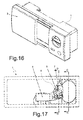
Fig.16 is a perspective view similar toFig. 1 of a second embodiment of a dispenser according to the invention, ready to dispense with the cover in the closed position; -
Fig.17 is a rear view of the dispenser ofFig.16 with a part of the body removed to show some internal components; -
Fig.18 is a sectional view along line C-C ofFig.17 ; -
Fig.19 is a sectional view along line D-D ofFig.17 ; -
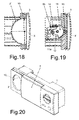
Fig.20 is a perspective view similar toFig.16 , with the cover in the open position and the tray in communication with the wash tank; -
Fig.21 is a rear view similar toFig.17 , with the components in the position corresponding to the condition ofFig.20 ; -
Fig.22 is a sectional view along line C-C ofFig.21 ; -
Fig.23 is a sectional view along line D-D ofFig.21 ; -
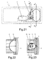
Fig.24 is a rear view similar toFig.21 , with the components in the position corresponding to the initial stage of activation of the means for the active dispensing of the detergent; -
Fig.25 is a sectional view along line C-C ofFig.24 ; -
Fig.26 is a sectional view along line D-D ofFig.24 ; -
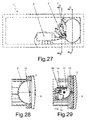
Fig.27 is a rear view similar toFig.24 , with the components in the position corresponding to the complete activation of the means for the active dispensing of the detergent; -
Fig.28 is a sectional view along line C-C ofFig.27 ; -
Fig.28 is a sectional view along line D-D ofFig.27 ; -
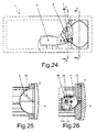
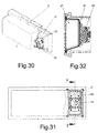
Fig.30 is a rear perspective view of a third embodiment of a dispenser according to the invention, with a portion of the bottom removed to show some internal components and with the cover in the open position; -
Fig.31 is a rear view of the dispenser ofFig.30 ; and -
Fig.28 is a sectional view along line E-E ofFig.31 ; - Referring to
Figures 1 to 5 , there is seen that a dispenser according to the invention conventionally includes abody 1 at one end of which there is inserted atray 2 for the load of the detergent which is closable by asliding cover 3 that is pushed open by a spring (not shown) when anactuator 4 unlocks a latch (not shown) that holds it in the closed position. Typically,actuator 4 does not act directly on the latch but rather on a rotatinglever 5 pivoted tobody 1 through apin 6 so as to rotate in the plane of the dishwasher door. Areturn spring 7 is arranged betweenbody 1 andlever 5 to operate in contrast toactuator 4, so as to bringlever 5 back to the initial rest position whenactuator 4 is turned off (spring 7 is only shown schematically inFig.2 and is omitted inFig.3 ). - A first novel aspect of the present dispenser, as mentioned above, lies in the presence on
tray 2 of means for the active dispensing of the detergent which essentially consist of apusher 8, externally fixed on the bottom oftray 2, and aspring 9 compressed betweenbody 1 and saidpusher 8 so as to push it outwards in the direction perpendicular to the plane of the door. - More specifically, as better shown in
Fig.4 ,pusher 8 is formed by arectangular plate 8a shaped and dimensioned for attachment to the bottom oftray 2, byperpendicular uprights 8b that extend from the short sides ofplate 8a and are provided withpegs 8c whose longitudinal axes are parallel toplate 8a, and by an L-shaped hook 8d which extends perpendicularly from the center ofplate 8a on the same side ofuprights 8b. - Pusher 8 is slidably mounted in
body 1, as better shown inFig.3 , throughpegs 8c which slide along guides formed by pairs ofribs 1a perpendicular to the plane of the door, whilehook 8d passing through acorresponding hole 1b protrudes to the rear of awall 1c that supportsspring 9. The purpose ofhook 8d is to act as a latch for the activation of the means for the active dispensing of the detergent, since once disengaged it allowsspring 9 to push outwardspusher 8 and with it tray 2 which is formed by a flexible membrane fixed tobody 1 only along its own perimeter. - In a second novel aspect of the present invention, the locking of
hook 8d in its rest position and its subsequent release are preferably achieved using the samerotating lever 5 moved byactuator 4 andspring 7. In this way, it is not necessary to add other electrical components for the activation of the means for the active dispensing of the detergent since use is made of the same components already present for the release ofcover 3. To this purpose,lever 5 extends up to hook 8d with an L-shapedarm 5a, whose end engageshook 8d thus keepingspring 9 compressed betweenwall 1c andplate 8a. - In the light of the description above, the simple and effective operation of the present dispenser is readily understood with the aid of
figures 6 to 15 . When the dishwasher door is open in a horizontal position with the dispenser open and empty, the user pours intray 2 the detergent powder or liquid (or inserts a tablet of detergent without its protective wrapping), and then closescover 3, thus obtaining the initial condition shown inFig.1 , in the same way that with a traditional dispenser. - Once closed the dishwasher door, in the established phase of the wash cycle the control unit of the machine activates
actuator 4 to releasecover 3 thus puttingtray 2 in communication with the wash tank (Fig.6 ). To this purpose,actuator 4 pusheslever 5 making it rotate aroundpin 6 against the resistance ofspring 7, and in these first few millimeters oftravel actuator 4 causes the unlocking of the latch ofcover 3 that slides sideways under the push of its spring as it normally occurs in traditional dispensers. Note that at the end of this firstrelease phase arm 5a still engageshook 8d (Fig.7 ), as is also evident fromFig.8 that differs fromFig.5 only for the absence ofcover 3. - Continuing in its travel,
actuator 4 performs a second release phase by continuing to rotatelever 5 untilarm 5a disengages fromhook 8d (Fig.9 ) and thus releasesplate 8a which keptspring 9 compressed. At thispoint spring 9 can pushplate 8a outwards (Fig.10 ) and with it the bottom oftray 2, so that the flexible membrane that acts as a detergent container is turned inside out allowing the complete emptying of the detergent (Fig.11 ). The linear and balanced movement ofpusher 8 under the action ofspring 9 is guaranteed bypegs 8c which slide in the guides ofbody 1 defined byribs 1a, ensuring a smooth passage ofhook 8d throughhole 1b ofwall 1c. - Note that at this
stage tray 2 is not only reversed from concave to convex, but it also protrudes toward the inside of the wash tank and is therefore subject to a certain washing action by water jets that bounce off from the dishes and by streams of water dripping down the door. - At the end of its operating phase,
actuator 4 is deactivated and returns to its rest position, together withlever 5, under the push of the return spring 7 (Fig.12 ) as normally occurs in traditional dispensers. This position of thecomponents Fig.2 , but in thiscondition arm 5a does not engagehook 8d which is on the other side ofwall 1c. To restore the actual initial condition and be able to reload the detergent intray 2 for the next wash cycle, the user must press on the bottom of tray 2 (Fig.13 ) pushing consequentlypusher 8 which, thanks topegs 8c, slides inguides 1a compressing spring 9 until it arrives in contact witharm 5a which is positioned in front ofhole 1b in correspondence with the hooking portion ofhook 8d (Fig.14 ). - Continuing the compression of
spring 9, by means of a coupling between two corresponding slanted surfaces formed on the faces ofcomponents Fig.15 wheretray 2 is omitted, the push of the user onpusher 8 also causes the rotation oflever 5 against the resistance ofspring 7 allowing the passage ofhook 8d. Once the hooking portion ofhook 8d has passed beyondarm 5a, thereturn spring 7 bringslever 5 back to its rest position so thatarm 5a returns to engagehook 8d as in the initial position ofFig.2 . In this condition,tray 2 is back to a concave shape and can accommodate detergent again, so that the user can reload the dispenser and manuallyclose cover 3 as it normally occurs in traditional dispensers. - Referring now to
figures 16 to 19 , there is illustrated a second embodiment of a dispenser according to the invention which differs from the first embodiment in the tray with the related means for the active dispensing of the detergent. There is no change in the operation of the spring-loaded slidingcover 3,Fig.16 being equal toFig.1 only seen from another angle, and ofactuator 4 which unlocks the latch thereof by acting onlever 5 which rotates aroundpin 6, with thereturn spring 7 arranged betweenbody 1 andlever 5 to return the latter to its initial position whenactuator 4 is turned off (Fig. 17 ). - In this second embodiment the means for the active dispensing of the detergent essentially consist of a
scraper 10 shaped and dimensioned to extend along half of the perimeter of tray 2'. The ends ofscraper 10 are pivoted to tray 2' so thatscraper 10 can rotate 180° around an axis X arranged in the plane of the door. In the path from a semi-perimeter to the other,scraper 10 scrapes the entire inner surface of tray 2' thus removing the detergent that may have stuck to it. - Note that tray 2' will therefore have a semicircular shape in a section along a plane perpendicular to the axis of rotation X (
Fig.18 ), but it can have any shape in a section along a plane perpendicular to said plane of section. In fact, tray 2' shown in the drawings occupies the same space of therectangular tray 2 of the first embodiment, therefore it does not have a hemispherical shape which however it could have if it were wider. - Also in this embodiment the rotation of
scraper 10 is preferably achieved by using the samerotating lever 5 moved byactuator 4 andspring 7, so as not to require other electrical components for the activation of the means for the active dispensing of the detergent. To this purpose,lever 5 is provided on its front face with aprotrusion 5b which engages with play atoothed sector 11, in correspondence of acavity 11a, which is pivoted tobody 1 through apin 12 so as to rotate in a plane perpendicular to the dishwasher door (Fig.19 ). Thistoothed sector 11 engages in turn atoothed wheel 13 coaxial with the axis of rotation X and integral with a shaft (not shown) on which is keyed the inner end ofscraper 10. Areturn spring 14 is also preferably arranged betweenbody 1 and thetoothed sector 11 to helpspring 7 return thetoothed sector 11 to the initial position whenactuator 4 is turned off. - In the light of the description above, the simple and effective operation of the second embodiment of the present dispenser is readily understood with the aid of
figures 20 to 29 . - When the control unit of the machine activates
actuator 4 to releasecover 3,actuator 4 pusheslever 5 making it rotate aroundpin 6 against the resistance ofspring 7. In these first few millimeters of travel,actuator 4 causes the unlocking of the latch ofcover 3 that slides sideways under the push of its spring as it normally occurs in traditional dispensers (Fig.20 ). Note that at the end of this release phase (Fig.21 )protrusion 5b has moved only withincavity 11 a and has not yet caused any rotation of the toothed sector 11 (Fig.23 ), as is also evident fromFig.22 that differs fromFig.18 only for the position ofcover 3. - Continuing in its travel,
actuator 4 continues to rotate lever 5 (Fig.24 ) so thatprojection 5b drives into rotation thetoothed sector 11 aroundpin 12 against the resistance of thereturn spring 14. This rotation of thetoothed sector 11, clockwise in the view ofFig.26 , in turn causes an opposite rotation (counterclockwise inFig.26 ) of thetoothed wheel 13 around axis X which results in a corresponding rotation ofscraper 10 in tray 2' (Fig.25 ). With a suitable calculation of the transmission ratio between thetoothed sector 11 and thetoothed wheel 13, whenactuator 4 has completed its travel (Fig.27 )scraper 10 has completed its 180° rotation (Fig.28 ), thus acting on the entire inner surface of tray 2' in order to ensure the dispensing of the detergent. - At the end of its operating phase,
actuator 4 is deactivated and returns to its rest position, together withlever 5, under the push of thereturn spring 7 as it normally occurs in traditional dispensers. Consequently, alsoprojection 5b returns to its rest position ofFig.19 causing, with the aid ofspring 14 which has reached the maximum extension (Fig.29 ), the reverse rotation of thetoothed sector 11 andtoothed wheel 13 which in turn bringsscraper 10 back to its rest position ofFig.18 . Therefore also the return travel ofscraper 10 is useful for scraping tray 2' in the opposite direction, to better guarantee the total removal of the detergent from the inner surface thereof. - Finally, making reference to
figures 30 to 32 , there is illustrated a third embodiment of the dispenser that differs from the previous ones always in the tray with the related means for the active dispensing of the detergent. The operation of the spring-loaded slidingcover 3, which is shown inFig.30 already in the open position, remains unchanged and is not repeated again here. - In this third embodiment, the means for the active dispensing of the detergent essentially consist of a vibrating
motor 15 fixed externally on the bottom oftray 2" by means of aplate 16, in a similar way to plate 8a of the first embodiment.Tray 2" is substantially rectangular and preferably also made astray 2 of the first embodiment, i.e. a flexible membrane fixed tobody 1 only along its own perimeter. - The only difference of
tray 2" resides in the lower side more inclined than the upper side, said sides being so defined in the operating position ofFig.32 , so as to facilitate the dispensing by gravity of the detergent. In fact, the simple operation of this dispenser consist in activating, after the opening ofcover 3, the vibratingmotor 15 which generates the vibration ofplate 16 and therefore oftray 2" allowing the detachment and complete dispensing of the detergent. Note thattray 2" might also have a rigid structure as tray 2', provided that it is flexibly attached tobody 1 so as to allow the vibratingmotor 15 to shake it effectively without transmitting excessive vibrations tobody 1 which would make noisy the dispenser operation. - Obviously, in this case, the activation of the means for the active dispensing of the detergent is independent from
actuator 4 that releasescover 3, since the vibratingmotor 15 is already in itself an electrical component that is switched on and off directly by the control unit of the dishwasher same asactuator 4. - It is clear that the embodiments of the dispenser according to the invention described and illustrated above are just examples susceptible of various modifications. In particular, the shape, size and arrangement of the tray for the load of the detergent can be varied according to the needs, as well as the means for moving
cover 3 and for the activation of the means for the active dispensing of the detergent. For example, in the first two embodiments there could be provided a specific electrical or mechanical component for said activation, such as a second actuator or a second lever driven byactuator 4. Moreover,actuator 4 rather than unlocking the latch of the spring-loadedcover 3 might directly control the movement ofcover 3, which would therefore not be spring-loaded.
Claims (12)
- Detergent dispenser for dishwasher comprising a body (1) in which there is arranged a tray (2; 2'; 2") for the load of the detergent which is closable by a cover (3) movable under the action of an actuator (4) between a closed position and an open position of said tray (2; 2'; 2"), characterized in that the tray (2; 2'; 2") is provided with means for the active dispensing of the detergent.
- Detergent dispenser for dishwasher according to claim 1, characterized in that the means for the active dispensing of the detergent are operatively connected to the actuator (4) so as to be activated by said actuator (4) after it has caused the displacement of the cover (3) to the open position of the tray (2; 2'; 2").
- Detergent dispenser for dishwasher according to claim 1 or 2, characterized in that the means for the active dispensing of the detergent essentially consist of a pusher (8), fixed externally on the bottom of the tray (2) and slidably mounted in the body (1), and a spring (9) compressed between a wall (1c) of the body (1) and said pusher (8) so as to push it outwards in the direction perpendicular to the plane of the door, the tray (2) being formed by a flexible membrane fixed to the body (1) only along its own perimeter in order to be able to be turned inside out passing from concave to convex.
- Detergent dispenser for dishwasher according to the preceding claim, characterized in that the pusher (8) is formed by a rectangular plate (8a) shaped and dimensioned for attachment to the bottom of the tray (2), by perpendicular uprights (8b) that extend from the short sides of said plate (8a) and are provided with pegs (8c) whose longitudinal axes are parallel to the plate (8a), and by an L-shaped hook (8d) that extends perpendicularly from the center of the plate (8a) on the same side of said perpendicular uprights (8b), the pusher (8) being slidably mounted in the body (1) by means of said pegs (8c) which slide along guides formed by pairs of ribs (1a) perpendicular to the plane of the door, said hook (8d) passing through a corresponding hole (1b) so as to protrude to the rear of the wall (1c) that supports the spring (9) in order to act as a latch to hold the means for the active dispensing of the detergent in the rest position.
- Detergent dispenser for dishwasher according to the preceding claim, characterized in that in the rest position the hook (8d) is engaged by an arm (5a) which extends from a lever (5) rotating in the plane of the door under the action of the actuator (4) that overcomes the resistance of a return spring (7), the faces of the hook (8d) and of said arm (5a) opposite to the faces in contact in said engagement condition being shaped as two corresponding slanted surfaces suitable to convert a push on the pusher (8) in the direction perpendicular to the plane of the door into a rotation of the lever (5) against the resistance of said spring (7) until the restoration of the engagement condition.
- Detergent dispenser for dishwasher according to claim 1 or 2, characterized in that the means for the active dispensing of the detergent essentially consist of a scraper (10) shaped and dimensioned to extend along half of the perimeter of the tray (2'), the ends of said scraper (10) being pivoted to the tray (2') so that the scraper (10) can rotate 180° around an axis of rotation (X) disposed in the plane of the door, the tray (2') having a semicircular shape at least in the section along a plane perpendicular to said axis of rotation (X).
- Detergent dispenser for dishwasher according to the preceding claim, characterized in that it includes a lever (5) rotating in the plane of the door under the action of the actuator (4) that overcomes the resistance of a return spring (7), said lever (5) being provided on its front face with a projection (5b) which engages with play a toothed sector (11) hinged to the body (1) so as to rotate in a plane perpendicular to the dishwasher door, said toothed sector (11) engaging in turn a toothed wheel (13) integral with a shaft on which is keyed one end of the scraper (10).
- Detergent dispenser for dishwasher according to the preceding claim, characterized in that it further comprises a return spring (14) arranged between the body (1) and the toothed sector (11) so as to bring it back to the initial position when the actuator (4) is turned off.
- Detergent dispenser for dishwasher according to claim 1, characterized in that the means for the active dispensing of the detergent essentially consist of a vibrating motor (15) fixed externally on the bottom of the tray (2") by means of a plate (16).
- Detergent dispenser for dishwasher according to the preceding claim, characterized in that the tray (2") is formed by a flexible membrane fixed to the body (1) only along its own perimeter or by a rigid structure flexibly attached to the body (1).
- Detergent dispenser for dishwasher according to claim 9 or 10, characterized in that the tray (2") is substantially rectangular and has a lower side more inclined than the upper side, said sides being so defined in the operating position for dispensing.
- Dishwasher, characterized in that it includes a detergent dispenser according to any of the preceding claims.
Priority Applications (2)
| Application Number | Priority Date | Filing Date | Title |
|---|---|---|---|
| PL14425028T PL2918215T3 (en) | 2014-03-14 | 2014-03-14 | Dishwasher including detergent dispenser |
| EP14425028.9A EP2918215B1 (en) | 2014-03-14 | 2014-03-14 | Dishwasher including detergent dispenser |
Applications Claiming Priority (1)
| Application Number | Priority Date | Filing Date | Title |
|---|---|---|---|
| EP14425028.9A EP2918215B1 (en) | 2014-03-14 | 2014-03-14 | Dishwasher including detergent dispenser |
Publications (2)
| Publication Number | Publication Date |
|---|---|
| EP2918215A1 true EP2918215A1 (en) | 2015-09-16 |
| EP2918215B1 EP2918215B1 (en) | 2018-10-17 |
Family
ID=50679984
Family Applications (1)
| Application Number | Title | Priority Date | Filing Date |
|---|---|---|---|
| EP14425028.9A Active EP2918215B1 (en) | 2014-03-14 | 2014-03-14 | Dishwasher including detergent dispenser |
Country Status (2)
| Country | Link |
|---|---|
| EP (1) | EP2918215B1 (en) |
| PL (1) | PL2918215T3 (en) |
Cited By (2)
| Publication number | Priority date | Publication date | Assignee | Title |
|---|---|---|---|---|
| CN108309183A (en) * | 2018-02-02 | 2018-07-24 | 广东浩喜电器科技有限公司 | A kind of small desk dish-washing machine of band washing consumptive material module |
| CN109199295A (en) * | 2017-07-03 | 2019-01-15 | 三花亚威科电器设备有限公司 | For distributing the device of detergent |
Families Citing this family (1)
| Publication number | Priority date | Publication date | Assignee | Title |
|---|---|---|---|---|
| CN110840367B (en) * | 2019-11-19 | 2021-03-19 | 佛山市顺德区美的洗涤电器制造有限公司 | Distributor and washing appliance |
Citations (6)
| Publication number | Priority date | Publication date | Assignee | Title |
|---|---|---|---|---|
| US4149657A (en) | 1977-05-20 | 1979-04-17 | General Electric Company | Dishwasher additive dispensing apparatus |
| DE3724849A1 (en) * | 1987-07-27 | 1989-02-09 | Bosch Siemens Hausgeraete | Washing-in device for powdered additional agents in dishwashers |
| DE4344205A1 (en) * | 1993-12-23 | 1995-06-29 | Aweco Kunststofftech Geraete | Cleaning agent dosing device for electric dishwashing machine |
| EP0780087A2 (en) | 1995-12-21 | 1997-06-25 | Bosch-Siemens HausgerÀ¤te GmbH | Device for dispensing a cleaning product, in particular for a dishwasher |
| US20120090463A1 (en) | 2009-04-09 | 2012-04-19 | Linde-Kca-Dresden Gmbh | Process and apparatus for the treatment of flue gases |
| EP2478819A1 (en) * | 2011-01-24 | 2012-07-25 | T & P - S.p.A. | A washing agent dispensing device for a washing machine for household use, in particular a dishwasher, and washing machine thereof |
Family Cites Families (2)
| Publication number | Priority date | Publication date | Assignee | Title |
|---|---|---|---|---|
| JPS6383164U (en) * | 1986-11-21 | 1988-06-01 | ||
| JP3736194B2 (en) * | 1999-04-22 | 2006-01-18 | 松下電器産業株式会社 | Dishwasher |
-
2014
- 2014-03-14 EP EP14425028.9A patent/EP2918215B1/en active Active
- 2014-03-14 PL PL14425028T patent/PL2918215T3/en unknown
Patent Citations (6)
| Publication number | Priority date | Publication date | Assignee | Title |
|---|---|---|---|---|
| US4149657A (en) | 1977-05-20 | 1979-04-17 | General Electric Company | Dishwasher additive dispensing apparatus |
| DE3724849A1 (en) * | 1987-07-27 | 1989-02-09 | Bosch Siemens Hausgeraete | Washing-in device for powdered additional agents in dishwashers |
| DE4344205A1 (en) * | 1993-12-23 | 1995-06-29 | Aweco Kunststofftech Geraete | Cleaning agent dosing device for electric dishwashing machine |
| EP0780087A2 (en) | 1995-12-21 | 1997-06-25 | Bosch-Siemens HausgerÀ¤te GmbH | Device for dispensing a cleaning product, in particular for a dishwasher |
| US20120090463A1 (en) | 2009-04-09 | 2012-04-19 | Linde-Kca-Dresden Gmbh | Process and apparatus for the treatment of flue gases |
| EP2478819A1 (en) * | 2011-01-24 | 2012-07-25 | T & P - S.p.A. | A washing agent dispensing device for a washing machine for household use, in particular a dishwasher, and washing machine thereof |
Cited By (2)
| Publication number | Priority date | Publication date | Assignee | Title |
|---|---|---|---|---|
| CN109199295A (en) * | 2017-07-03 | 2019-01-15 | 三花亚威科电器设备有限公司 | For distributing the device of detergent |
| CN108309183A (en) * | 2018-02-02 | 2018-07-24 | 广东浩喜电器科技有限公司 | A kind of small desk dish-washing machine of band washing consumptive material module |
Also Published As
| Publication number | Publication date |
|---|---|
| PL2918215T3 (en) | 2019-07-31 |
| EP2918215B1 (en) | 2018-10-17 |
Similar Documents
| Publication | Publication Date | Title |
|---|---|---|
| EP1740082B1 (en) | An integrated washing agent dispenser, in particular for a dishwasher | |
| CN110279368B (en) | Distributor and washing appliance | |
| CN110279370B (en) | Distributor and washing appliance | |
| CN110279369B (en) | Distributor and washing electric appliance | |
| EP2918215A1 (en) | Detergent dispenser for dishwasher | |
| US11497380B2 (en) | Detergent cartridge for a dishwasher incorporating detergent dispensing verification | |
| CN110393491B (en) | Distributor and washing appliance | |
| US7699063B2 (en) | Dispenser for a drawer-type dishwasher | |
| US3125249A (en) | Dishwasher with improved treating agent dispenser mechanism | |
| WO2003053213A1 (en) | A dispenser of washing agents for a household washing machine, in particular a dish-washer | |
| WO2021004158A1 (en) | Distributor and washing appliance | |
| EP2478819B1 (en) | A washing agent dispensing device for a washing machine for household use, in particular a dishwasher, and washing machine thereof | |
| EP3860422B1 (en) | A dishwasher comprising a detergent dispenser | |
| CN110742562B (en) | Distributor and washing appliance | |
| CN211093868U (en) | Distributor and washing appliance | |
| CN110279380A (en) | Distributor and washing electric appliance | |
| EP3981313A1 (en) | Dispenser and washing appliance | |
| CN210871416U (en) | Distributor and washing appliance | |
| CN210673249U (en) | Distributor and washing appliance | |
| CN210673272U (en) | Distributor and washing appliance | |
| EP2540903B1 (en) | Device for dispensing detergent in a laundry washing machine and associated washing machine | |
| CN110833377B (en) | Distributor and washing appliance | |
| CN210673248U (en) | Distributor and washing appliance | |
| EP2540904B1 (en) | Detergent dispensing device for a laundry washing machine and associated washing machine | |
| CN210673271U (en) | Dispensing device and washing appliance |
Legal Events
| Date | Code | Title | Description |
|---|---|---|---|
| PUAI | Public reference made under article 153(3) epc to a published international application that has entered the european phase |
Free format text: ORIGINAL CODE: 0009012 |
|
| AK | Designated contracting states |
Kind code of ref document: A1 Designated state(s): AL AT BE BG CH CY CZ DE DK EE ES FI FR GB GR HR HU IE IS IT LI LT LU LV MC MK MT NL NO PL PT RO RS SE SI SK SM TR |
|
| AX | Request for extension of the european patent |
Extension state: BA ME |
|
| 17P | Request for examination filed |
Effective date: 20150928 |
|
| RBV | Designated contracting states (corrected) |
Designated state(s): AL AT BE BG CH CY CZ DE DK EE ES FI FR GB GR HR HU IE IS IT LI LT LU LV MC MK MT NL NO PL PT RO RS SE SI SK SM TR |
|
| 17Q | First examination report despatched |
Effective date: 20160104 |
|
| STAA | Information on the status of an ep patent application or granted ep patent |
Free format text: STATUS: EXAMINATION IS IN PROGRESS |
|
| GRAJ | Information related to disapproval of communication of intention to grant by the applicant or resumption of examination proceedings by the epo deleted |
Free format text: ORIGINAL CODE: EPIDOSDIGR1 |
|
| GRAP | Despatch of communication of intention to grant a patent |
Free format text: ORIGINAL CODE: EPIDOSNIGR1 |
|
| GRAP | Despatch of communication of intention to grant a patent |
Free format text: ORIGINAL CODE: EPIDOSNIGR1 |
|
| STAA | Information on the status of an ep patent application or granted ep patent |
Free format text: STATUS: GRANT OF PATENT IS INTENDED |
|
| INTG | Intention to grant announced |
Effective date: 20180613 |
|
| GRAS | Grant fee paid |
Free format text: ORIGINAL CODE: EPIDOSNIGR3 |
|
| GRAA | (expected) grant |
Free format text: ORIGINAL CODE: 0009210 |
|
| STAA | Information on the status of an ep patent application or granted ep patent |
Free format text: STATUS: THE PATENT HAS BEEN GRANTED |
|
| AK | Designated contracting states |
Kind code of ref document: B1 Designated state(s): AL AT BE BG CH CY CZ DE DK EE ES FI FR GB GR HR HU IE IS IT LI LT LU LV MC MK MT NL NO PL PT RO RS SE SI SK SM TR |
|
| REG | Reference to a national code |
Ref country code: GB Ref legal event code: FG4D |
|
| REG | Reference to a national code |
Ref country code: CH Ref legal event code: EP |
|
| REG | Reference to a national code |
Ref country code: IE Ref legal event code: FG4D |
|
| REG | Reference to a national code |
Ref country code: DE Ref legal event code: R096 Ref document number: 602014034176 Country of ref document: DE Ref country code: AT Ref legal event code: REF Ref document number: 1052994 Country of ref document: AT Kind code of ref document: T Effective date: 20181115 |
|
| REG | Reference to a national code |
Ref country code: NL Ref legal event code: FP |
|
| REG | Reference to a national code |
Ref country code: LT Ref legal event code: MG4D |
|
| REG | Reference to a national code |
Ref country code: AT Ref legal event code: MK05 Ref document number: 1052994 Country of ref document: AT Kind code of ref document: T Effective date: 20181017 |
|
| PG25 | Lapsed in a contracting state [announced via postgrant information from national office to epo] |
Ref country code: ES Free format text: LAPSE BECAUSE OF FAILURE TO SUBMIT A TRANSLATION OF THE DESCRIPTION OR TO PAY THE FEE WITHIN THE PRESCRIBED TIME-LIMIT Effective date: 20181017 Ref country code: LV Free format text: LAPSE BECAUSE OF FAILURE TO SUBMIT A TRANSLATION OF THE DESCRIPTION OR TO PAY THE FEE WITHIN THE PRESCRIBED TIME-LIMIT Effective date: 20181017 Ref country code: BG Free format text: LAPSE BECAUSE OF FAILURE TO SUBMIT A TRANSLATION OF THE DESCRIPTION OR TO PAY THE FEE WITHIN THE PRESCRIBED TIME-LIMIT Effective date: 20190117 Ref country code: HR Free format text: LAPSE BECAUSE OF FAILURE TO SUBMIT A TRANSLATION OF THE DESCRIPTION OR TO PAY THE FEE WITHIN THE PRESCRIBED TIME-LIMIT Effective date: 20181017 Ref country code: NO Free format text: LAPSE BECAUSE OF FAILURE TO SUBMIT A TRANSLATION OF THE DESCRIPTION OR TO PAY THE FEE WITHIN THE PRESCRIBED TIME-LIMIT Effective date: 20190117 Ref country code: LT Free format text: LAPSE BECAUSE OF FAILURE TO SUBMIT A TRANSLATION OF THE DESCRIPTION OR TO PAY THE FEE WITHIN THE PRESCRIBED TIME-LIMIT Effective date: 20181017 Ref country code: FI Free format text: LAPSE BECAUSE OF FAILURE TO SUBMIT A TRANSLATION OF THE DESCRIPTION OR TO PAY THE FEE WITHIN THE PRESCRIBED TIME-LIMIT Effective date: 20181017 Ref country code: IS Free format text: LAPSE BECAUSE OF FAILURE TO SUBMIT A TRANSLATION OF THE DESCRIPTION OR TO PAY THE FEE WITHIN THE PRESCRIBED TIME-LIMIT Effective date: 20190217 Ref country code: AT Free format text: LAPSE BECAUSE OF FAILURE TO SUBMIT A TRANSLATION OF THE DESCRIPTION OR TO PAY THE FEE WITHIN THE PRESCRIBED TIME-LIMIT Effective date: 20181017 |
|
| PG25 | Lapsed in a contracting state [announced via postgrant information from national office to epo] |
Ref country code: AL Free format text: LAPSE BECAUSE OF FAILURE TO SUBMIT A TRANSLATION OF THE DESCRIPTION OR TO PAY THE FEE WITHIN THE PRESCRIBED TIME-LIMIT Effective date: 20181017 Ref country code: SE Free format text: LAPSE BECAUSE OF FAILURE TO SUBMIT A TRANSLATION OF THE DESCRIPTION OR TO PAY THE FEE WITHIN THE PRESCRIBED TIME-LIMIT Effective date: 20181017 Ref country code: PT Free format text: LAPSE BECAUSE OF FAILURE TO SUBMIT A TRANSLATION OF THE DESCRIPTION OR TO PAY THE FEE WITHIN THE PRESCRIBED TIME-LIMIT Effective date: 20190217 Ref country code: RS Free format text: LAPSE BECAUSE OF FAILURE TO SUBMIT A TRANSLATION OF THE DESCRIPTION OR TO PAY THE FEE WITHIN THE PRESCRIBED TIME-LIMIT Effective date: 20181017 Ref country code: GR Free format text: LAPSE BECAUSE OF FAILURE TO SUBMIT A TRANSLATION OF THE DESCRIPTION OR TO PAY THE FEE WITHIN THE PRESCRIBED TIME-LIMIT Effective date: 20190118 |
|
| REG | Reference to a national code |
Ref country code: DE Ref legal event code: R097 Ref document number: 602014034176 Country of ref document: DE |
|
| PG25 | Lapsed in a contracting state [announced via postgrant information from national office to epo] |
Ref country code: CZ Free format text: LAPSE BECAUSE OF FAILURE TO SUBMIT A TRANSLATION OF THE DESCRIPTION OR TO PAY THE FEE WITHIN THE PRESCRIBED TIME-LIMIT Effective date: 20181017 Ref country code: DK Free format text: LAPSE BECAUSE OF FAILURE TO SUBMIT A TRANSLATION OF THE DESCRIPTION OR TO PAY THE FEE WITHIN THE PRESCRIBED TIME-LIMIT Effective date: 20181017 |
|
| PLBE | No opposition filed within time limit |
Free format text: ORIGINAL CODE: 0009261 |
|
| STAA | Information on the status of an ep patent application or granted ep patent |
Free format text: STATUS: NO OPPOSITION FILED WITHIN TIME LIMIT |
|
| PG25 | Lapsed in a contracting state [announced via postgrant information from national office to epo] |
Ref country code: SM Free format text: LAPSE BECAUSE OF FAILURE TO SUBMIT A TRANSLATION OF THE DESCRIPTION OR TO PAY THE FEE WITHIN THE PRESCRIBED TIME-LIMIT Effective date: 20181017 Ref country code: EE Free format text: LAPSE BECAUSE OF FAILURE TO SUBMIT A TRANSLATION OF THE DESCRIPTION OR TO PAY THE FEE WITHIN THE PRESCRIBED TIME-LIMIT Effective date: 20181017 Ref country code: SK Free format text: LAPSE BECAUSE OF FAILURE TO SUBMIT A TRANSLATION OF THE DESCRIPTION OR TO PAY THE FEE WITHIN THE PRESCRIBED TIME-LIMIT Effective date: 20181017 Ref country code: RO Free format text: LAPSE BECAUSE OF FAILURE TO SUBMIT A TRANSLATION OF THE DESCRIPTION OR TO PAY THE FEE WITHIN THE PRESCRIBED TIME-LIMIT Effective date: 20181017 |
|
| 26N | No opposition filed |
Effective date: 20190718 |
|
| PG25 | Lapsed in a contracting state [announced via postgrant information from national office to epo] |
Ref country code: SI Free format text: LAPSE BECAUSE OF FAILURE TO SUBMIT A TRANSLATION OF THE DESCRIPTION OR TO PAY THE FEE WITHIN THE PRESCRIBED TIME-LIMIT Effective date: 20181017 Ref country code: MC Free format text: LAPSE BECAUSE OF FAILURE TO SUBMIT A TRANSLATION OF THE DESCRIPTION OR TO PAY THE FEE WITHIN THE PRESCRIBED TIME-LIMIT Effective date: 20181017 |
|
| REG | Reference to a national code |
Ref country code: CH Ref legal event code: PL |
|
| PG25 | Lapsed in a contracting state [announced via postgrant information from national office to epo] |
Ref country code: LU Free format text: LAPSE BECAUSE OF NON-PAYMENT OF DUE FEES Effective date: 20190314 |
|
| REG | Reference to a national code |
Ref country code: BE Ref legal event code: MM Effective date: 20190331 |
|
| PG25 | Lapsed in a contracting state [announced via postgrant information from national office to epo] |
Ref country code: LI Free format text: LAPSE BECAUSE OF NON-PAYMENT OF DUE FEES Effective date: 20190331 Ref country code: IE Free format text: LAPSE BECAUSE OF NON-PAYMENT OF DUE FEES Effective date: 20190314 Ref country code: CH Free format text: LAPSE BECAUSE OF NON-PAYMENT OF DUE FEES Effective date: 20190331 |
|
| PG25 | Lapsed in a contracting state [announced via postgrant information from national office to epo] |
Ref country code: BE Free format text: LAPSE BECAUSE OF NON-PAYMENT OF DUE FEES Effective date: 20190331 |
|
| PG25 | Lapsed in a contracting state [announced via postgrant information from national office to epo] |
Ref country code: TR Free format text: LAPSE BECAUSE OF FAILURE TO SUBMIT A TRANSLATION OF THE DESCRIPTION OR TO PAY THE FEE WITHIN THE PRESCRIBED TIME-LIMIT Effective date: 20181017 |
|
| PGFP | Annual fee paid to national office [announced via postgrant information from national office to epo] |
Ref country code: NL Payment date: 20200319 Year of fee payment: 7 Ref country code: PL Payment date: 20200221 Year of fee payment: 7 |
|
| PG25 | Lapsed in a contracting state [announced via postgrant information from national office to epo] |
Ref country code: MT Free format text: LAPSE BECAUSE OF NON-PAYMENT OF DUE FEES Effective date: 20190314 |
|
| PG25 | Lapsed in a contracting state [announced via postgrant information from national office to epo] |
Ref country code: CY Free format text: LAPSE BECAUSE OF FAILURE TO SUBMIT A TRANSLATION OF THE DESCRIPTION OR TO PAY THE FEE WITHIN THE PRESCRIBED TIME-LIMIT Effective date: 20181017 |
|
| PG25 | Lapsed in a contracting state [announced via postgrant information from national office to epo] |
Ref country code: HU Free format text: LAPSE BECAUSE OF FAILURE TO SUBMIT A TRANSLATION OF THE DESCRIPTION OR TO PAY THE FEE WITHIN THE PRESCRIBED TIME-LIMIT; INVALID AB INITIO Effective date: 20140314 |
|
| REG | Reference to a national code |
Ref country code: NL Ref legal event code: MM Effective date: 20210401 |
|
| PG25 | Lapsed in a contracting state [announced via postgrant information from national office to epo] |
Ref country code: NL Free format text: LAPSE BECAUSE OF NON-PAYMENT OF DUE FEES Effective date: 20210401 |
|
| PG25 | Lapsed in a contracting state [announced via postgrant information from national office to epo] |
Ref country code: MK Free format text: LAPSE BECAUSE OF FAILURE TO SUBMIT A TRANSLATION OF THE DESCRIPTION OR TO PAY THE FEE WITHIN THE PRESCRIBED TIME-LIMIT Effective date: 20181017 |
|
| PG25 | Lapsed in a contracting state [announced via postgrant information from national office to epo] |
Ref country code: PL Free format text: LAPSE BECAUSE OF NON-PAYMENT OF DUE FEES Effective date: 20210314 |
|
| PGFP | Annual fee paid to national office [announced via postgrant information from national office to epo] |
Ref country code: FR Payment date: 20230324 Year of fee payment: 10 |
|
| PGFP | Annual fee paid to national office [announced via postgrant information from national office to epo] |
Ref country code: IT Payment date: 20230317 Year of fee payment: 10 Ref country code: GB Payment date: 20230322 Year of fee payment: 10 Ref country code: DE Payment date: 20230321 Year of fee payment: 10 |
|
| P01 | Opt-out of the competence of the unified patent court (upc) registered |
Effective date: 20230606 |