EP2917620B1 - Valve device - Google Patents
Valve device Download PDFInfo
- Publication number
- EP2917620B1 EP2917620B1 EP13786672.9A EP13786672A EP2917620B1 EP 2917620 B1 EP2917620 B1 EP 2917620B1 EP 13786672 A EP13786672 A EP 13786672A EP 2917620 B1 EP2917620 B1 EP 2917620B1
- Authority
- EP
- European Patent Office
- Prior art keywords
- housing
- valve
- coupling device
- protective panel
- control shaft
- Prior art date
- Legal status (The legal status is an assumption and is not a legal conclusion. Google has not performed a legal analysis and makes no representation as to the accuracy of the status listed.)
- Active
Links
- 230000008878 coupling Effects 0.000 claims description 53
- 238000010168 coupling process Methods 0.000 claims description 53
- 238000005859 coupling reaction Methods 0.000 claims description 53
- 230000001681 protective effect Effects 0.000 claims description 40
- 125000006850 spacer group Chemical group 0.000 claims description 6
- 210000000078 claw Anatomy 0.000 claims description 2
- 239000012530 fluid Substances 0.000 claims description 2
- 238000007789 sealing Methods 0.000 description 25
- 230000005540 biological transmission Effects 0.000 description 9
- 238000001816 cooling Methods 0.000 description 4
- 238000005192 partition Methods 0.000 description 4
- 238000009423 ventilation Methods 0.000 description 4
- 230000000295 complement effect Effects 0.000 description 3
- 239000000919 ceramic Substances 0.000 description 2
- 235000013361 beverage Nutrition 0.000 description 1
- 239000000498 cooling water Substances 0.000 description 1
- 230000007547 defect Effects 0.000 description 1
- 230000009365 direct transmission Effects 0.000 description 1
- 230000000694 effects Effects 0.000 description 1
- 238000009434 installation Methods 0.000 description 1
- 239000007788 liquid Substances 0.000 description 1
- 238000004519 manufacturing process Methods 0.000 description 1
- 239000002245 particle Substances 0.000 description 1
- 230000002265 prevention Effects 0.000 description 1
- XLYOFNOQVPJJNP-UHFFFAOYSA-N water Substances O XLYOFNOQVPJJNP-UHFFFAOYSA-N 0.000 description 1
Images


Classifications
-
- F—MECHANICAL ENGINEERING; LIGHTING; HEATING; WEAPONS; BLASTING
- F16—ENGINEERING ELEMENTS AND UNITS; GENERAL MEASURES FOR PRODUCING AND MAINTAINING EFFECTIVE FUNCTIONING OF MACHINES OR INSTALLATIONS; THERMAL INSULATION IN GENERAL
- F16K—VALVES; TAPS; COCKS; ACTUATING-FLOATS; DEVICES FOR VENTING OR AERATING
- F16K1/00—Lift valves or globe valves, i.e. cut-off apparatus with closure members having at least a component of their opening and closing motion perpendicular to the closing faces
- F16K1/32—Details
-
- F—MECHANICAL ENGINEERING; LIGHTING; HEATING; WEAPONS; BLASTING
- F16—ENGINEERING ELEMENTS AND UNITS; GENERAL MEASURES FOR PRODUCING AND MAINTAINING EFFECTIVE FUNCTIONING OF MACHINES OR INSTALLATIONS; THERMAL INSULATION IN GENERAL
- F16L—PIPES; JOINTS OR FITTINGS FOR PIPES; SUPPORTS FOR PIPES, CABLES OR PROTECTIVE TUBING; MEANS FOR THERMAL INSULATION IN GENERAL
- F16L37/00—Couplings of the quick-acting type
- F16L37/02—Couplings of the quick-acting type in which the connection is maintained only by friction of the parts being joined
-
- F—MECHANICAL ENGINEERING; LIGHTING; HEATING; WEAPONS; BLASTING
- F16—ENGINEERING ELEMENTS AND UNITS; GENERAL MEASURES FOR PRODUCING AND MAINTAINING EFFECTIVE FUNCTIONING OF MACHINES OR INSTALLATIONS; THERMAL INSULATION IN GENERAL
- F16J—PISTONS; CYLINDERS; SEALINGS
- F16J15/00—Sealings
- F16J15/44—Free-space packings
- F16J15/447—Labyrinth packings
-
- F—MECHANICAL ENGINEERING; LIGHTING; HEATING; WEAPONS; BLASTING
- F16—ENGINEERING ELEMENTS AND UNITS; GENERAL MEASURES FOR PRODUCING AND MAINTAINING EFFECTIVE FUNCTIONING OF MACHINES OR INSTALLATIONS; THERMAL INSULATION IN GENERAL
- F16K—VALVES; TAPS; COCKS; ACTUATING-FLOATS; DEVICES FOR VENTING OR AERATING
- F16K1/00—Lift valves or globe valves, i.e. cut-off apparatus with closure members having at least a component of their opening and closing motion perpendicular to the closing faces
- F16K1/16—Lift valves or globe valves, i.e. cut-off apparatus with closure members having at least a component of their opening and closing motion perpendicular to the closing faces with pivoted closure-members
- F16K1/18—Lift valves or globe valves, i.e. cut-off apparatus with closure members having at least a component of their opening and closing motion perpendicular to the closing faces with pivoted closure-members with pivoted discs or flaps
- F16K1/22—Lift valves or globe valves, i.e. cut-off apparatus with closure members having at least a component of their opening and closing motion perpendicular to the closing faces with pivoted closure-members with pivoted discs or flaps with axis of rotation crossing the valve member, e.g. butterfly valves
- F16K1/221—Lift valves or globe valves, i.e. cut-off apparatus with closure members having at least a component of their opening and closing motion perpendicular to the closing faces with pivoted closure-members with pivoted discs or flaps with axis of rotation crossing the valve member, e.g. butterfly valves specially adapted operating means therefor
-
- F—MECHANICAL ENGINEERING; LIGHTING; HEATING; WEAPONS; BLASTING
- F16—ENGINEERING ELEMENTS AND UNITS; GENERAL MEASURES FOR PRODUCING AND MAINTAINING EFFECTIVE FUNCTIONING OF MACHINES OR INSTALLATIONS; THERMAL INSULATION IN GENERAL
- F16K—VALVES; TAPS; COCKS; ACTUATING-FLOATS; DEVICES FOR VENTING OR AERATING
- F16K11/00—Multiple-way valves, e.g. mixing valves; Pipe fittings incorporating such valves
- F16K11/02—Multiple-way valves, e.g. mixing valves; Pipe fittings incorporating such valves with all movable sealing faces moving as one unit
- F16K11/06—Multiple-way valves, e.g. mixing valves; Pipe fittings incorporating such valves with all movable sealing faces moving as one unit comprising only sliding valves, i.e. sliding closure elements
- F16K11/072—Multiple-way valves, e.g. mixing valves; Pipe fittings incorporating such valves with all movable sealing faces moving as one unit comprising only sliding valves, i.e. sliding closure elements with pivoted closure members
- F16K11/074—Multiple-way valves, e.g. mixing valves; Pipe fittings incorporating such valves with all movable sealing faces moving as one unit comprising only sliding valves, i.e. sliding closure elements with pivoted closure members with flat sealing faces
-
- F—MECHANICAL ENGINEERING; LIGHTING; HEATING; WEAPONS; BLASTING
- F16—ENGINEERING ELEMENTS AND UNITS; GENERAL MEASURES FOR PRODUCING AND MAINTAINING EFFECTIVE FUNCTIONING OF MACHINES OR INSTALLATIONS; THERMAL INSULATION IN GENERAL
- F16K—VALVES; TAPS; COCKS; ACTUATING-FLOATS; DEVICES FOR VENTING OR AERATING
- F16K15/00—Check valves
- F16K15/02—Check valves with guided rigid valve members
- F16K15/06—Check valves with guided rigid valve members with guided stems
- F16K15/063—Check valves with guided rigid valve members with guided stems the valve being loaded by a spring
-
- F—MECHANICAL ENGINEERING; LIGHTING; HEATING; WEAPONS; BLASTING
- F16—ENGINEERING ELEMENTS AND UNITS; GENERAL MEASURES FOR PRODUCING AND MAINTAINING EFFECTIVE FUNCTIONING OF MACHINES OR INSTALLATIONS; THERMAL INSULATION IN GENERAL
- F16K—VALVES; TAPS; COCKS; ACTUATING-FLOATS; DEVICES FOR VENTING OR AERATING
- F16K27/00—Construction of housing; Use of materials therefor
- F16K27/04—Construction of housing; Use of materials therefor of sliding valves
- F16K27/044—Construction of housing; Use of materials therefor of sliding valves slide valves with flat obturating members
- F16K27/045—Construction of housing; Use of materials therefor of sliding valves slide valves with flat obturating members with pivotal obturating members
-
- F—MECHANICAL ENGINEERING; LIGHTING; HEATING; WEAPONS; BLASTING
- F16—ENGINEERING ELEMENTS AND UNITS; GENERAL MEASURES FOR PRODUCING AND MAINTAINING EFFECTIVE FUNCTIONING OF MACHINES OR INSTALLATIONS; THERMAL INSULATION IN GENERAL
- F16K—VALVES; TAPS; COCKS; ACTUATING-FLOATS; DEVICES FOR VENTING OR AERATING
- F16K31/00—Actuating devices; Operating means; Releasing devices
- F16K31/02—Actuating devices; Operating means; Releasing devices electric; magnetic
- F16K31/04—Actuating devices; Operating means; Releasing devices electric; magnetic using a motor
- F16K31/041—Actuating devices; Operating means; Releasing devices electric; magnetic using a motor for rotating valves
- F16K31/043—Actuating devices; Operating means; Releasing devices electric; magnetic using a motor for rotating valves characterised by mechanical means between the motor and the valve, e.g. lost motion means reducing backlash, clutches, brakes or return means
-
- G—PHYSICS
- G01—MEASURING; TESTING
- G01F—MEASURING VOLUME, VOLUME FLOW, MASS FLOW OR LIQUID LEVEL; METERING BY VOLUME
- G01F1/00—Measuring the volume flow or mass flow of fluid or fluent solid material wherein the fluid passes through a meter in a continuous flow
- G01F1/05—Measuring the volume flow or mass flow of fluid or fluent solid material wherein the fluid passes through a meter in a continuous flow by using mechanical effects
- G01F1/10—Measuring the volume flow or mass flow of fluid or fluent solid material wherein the fluid passes through a meter in a continuous flow by using mechanical effects using rotating vanes with axial admission
- G01F1/115—Measuring the volume flow or mass flow of fluid or fluent solid material wherein the fluid passes through a meter in a continuous flow by using mechanical effects using rotating vanes with axial admission with magnetic or electromagnetic coupling to the indicating device
Definitions
- the invention relates to a valve device according to the preamble features of claim 1, such as from document WO-A-02/059515 known.
- Valve devices are used, for example, in motor vehicles for the regulation of cooling water circuits or in beverage vending machines.
- a disc valve device which comprises a disc valve and a drive unit.
- the disc valve has a first housing, in which the elements necessary for setting desired flow cross-sections, such as a rotatably mounted valve disc, are arranged.
- the drive unit has an electromechanical drive device, which is arranged in a second housing.
- the first housing is arranged at a distance from the second housing, wherein a drive shaft of the drive device protrudes from the second housing out into the first housing, where it is positively connected to the rotational drive with the valve disc.
- the assembly of the disc valve device is characterized relatively difficult and is not suitable in particular for the use of a simple modular system during assembly.
- WO 02/059515 A1 discloses a valve device in which the housing of a drive unit and a valve unit are connected to each other via a circumferentially closed and fixed to both housings cylinder element in the region of a coupling device.
- the invention has for its object to provide a valve device which provides a simple and inexpensive way an improved connection between the housings.
- valve device having the features of claim 1.
- the valve device according to the invention in particular disk valve device, has the advantage that the valve, in particular disk valve, and the drive unit are connected to each other in the area between the housings for torque transmission.
- the coupling point from drive unit to valve / disc valve is in an easily accessible area and allows the disc valve and the drive unit can be completely pre-assembled before they are merged to form the valve device or disc valve device.
- the assembly is simplified and it can be combined in a simple manner different valves / disc valves with different drive units, whereby the use of a modular system is made possible during assembly.
- the invention is characterized in that the disk valve has a control shaft and the drive unit has a drive shaft operatively connected to the drive device and operatively connected to the control shaft by a coupling device, and in that the coupling device is arranged between the first and the second housing.
- a shaft protrudes from the first as well as from the second housing into the intermediate space between the two housings in order to be operatively connected to one another there by the coupling device.
- the coupling device is designed as a positive coupling.
- the positive coupling allows the direct transmission of torque from the control shaft to the drive shaft.
- the positive coupling is formed in the rotational direction at least substantially free of play, so that a precise adjustment or actuation of the disc valve is ensured.
- the form-fitting coupling is formed with play in axial direction in order to be able to compensate for temperature-related or tolerance-related differences in length of the two shafts and / or the housing.
- the coupling device is designed as a tooth or dog clutch.
- the coupling device can be formed by integrally formed on the drive shaft and the control shaft rotational drive elements or integrally by the drive shaft and the control shaft itself.
- the teeth or claws can be arranged according to an embodiment on the end face of the respective shaft.
- the coupling device is formed by an external toothing of the control shaft and an internal toothing of the drive shaft which is in engagement with the external toothing.
- the control shaft thus protrudes partially with its free end in a hollow shaft portion of the drive shaft in order to effect the torque transmission there by external teeth and internal teeth.
- the coupling device is formed by drive shaft and control shaft itself.
- the external toothing is provided on the drive shaft and the internal toothing on the control shaft.
- the drive shaft and the control shaft are preferably connected to one another in a form-fitting manner for torque transmission by mutually complementary polygonal shapes.
- the coupling device is associated with a splash guard.
- the splash guard prevents moisture, for example splash water, from reaching the coupling device during operation and from the latter into the drive unit or into the disk valve. Through the splash guard, the life of the valve device is increased overall.
- the splash guard has at least one first protective wall surrounding the coupling device at least substantially circumferentially.
- This protective wall may be formed completely continuous or with one or more recesses or interruptions, which are used in particular for ventilation and cooling of the coupling device.
- the protective wall extends between the so both housings that it extends from one housing at least substantially to the other housing.
- the recesses in the protective wall preferably also serve for dewatering in the event of a component leakage of the disk valve. In the case of an error or defect or even if due to extreme system conditions, a brief leakage occurs, liquid can escape through the recesses to the outside, so that the drive unit is protected from exiting the valve fluid.
- the splash guard has at least one second protective wall surrounding the coupling device at least substantially, which has a larger or smaller diameter than the first protective wall in order to form a labyrinth seal for the coupling device together with the first protective wall.
- the second protective wall is preferably formed with one or more recesses or interruptions for ventilation or cooling of the coupling device.
- the recesses of the first protective wall and the second protective wall are arranged offset from one another to ensure a full splash protection. Due to the different diameters, the first and the second protective wall are inserted into one another during assembly, for which purpose they are expediently mounted coaxially with one another Condition of the housing are arranged.
- a gap between the protective walls is advantageously formed, which can be used in particular for drainage.
- the first protective wall is formed integrally with the first housing and the second protective wall is formed integrally with the second housing.
- the labyrinth seal is produced by means of the two protective walls by merging the two housings.
- the protective walls are preferably arranged at their respective free end sides at least partially spaced from the respective opposite housing or formed to ensure additional ventilation / cooling, and in particular to avoid over-determined storage of the housing to each other.
- the first and / or the second housing has at least one spacer, which is designed in particular as a screw-on dome.
- the spacers secure the distance between the two housings and the positioning of the shaft ends of the drive shaft and control shaft to each other.
- At least one of the spacers can also be formed by the splash guard or by one of the protective walls. Due to the preferred embodiment of the spacers in each case as a screw-on dome, the spacers simultaneously provide the fastening device for fastening the two housings together.
- the respective Anschraubdom is characterized by an internal thread, which is integrally formed by the Anschraubdom or by an inserted into the respective Anschraubdom threaded member, and in which a screw for fixing the one housing to the other housing can be screwed.
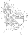
- FIG. 1 shows a designed as a disc valve device valve device 1, which has a disc valve 2 and a drive unit 3, in a perspective view.
- the disk valve 2 has a housing 4, which is formed by a distributor housing 5 and a cover 6.
- the distributor housing 5 has three connections, one of which is designed as an inlet connection 7, and the other two as outlet connections 8 and 9, respectively.
- the distributor housing 5 has a holding device 10 for fastening the valve device 1, for example to a body of a motor vehicle.
- the drive unit 3 is mounted, which is designed in particular as an electromotive actuator and this purpose an electric motor 59, not shown, as well as an operatively connected to the electric motor 59 gear 60 with a drive shaft 70th which can be coupled to a control shaft of the disk valve 2 in order to distribute a medium provided at the inlet connection 7 to the outlet connections 8, 9 as desired. This will be discussed further below.
- FIG. 2 shows the disc valve 2 in a longitudinal sectional view.
- the distributor housing 5 is formed substantially cup-shaped, so that it has a U-shaped basic shape seen in longitudinal section.
- the terminals 7, 8, 9 are in this case formed integrally with the distributor housing 5.
- the cover 6 closes the open end of the distributor housing 5, wherein between the cover 6 and the distributor housing 5 in addition a sealing element 11, which is in the present case designed as an O-ring, is provided.
- the inflow port 7 opens - seen axially - above the drain port 8 in the manifold housing 5, ie close to the lid 6.
- From the lid 6 opposite bottom 12 of the manifold housing 5 is a partition 13, which is parallel to the longitudinal extent of the manifold housing 5 and extends axially and ends above the terminal 8 forming an intermediate bottom 14 with its free end face.
- FIG. 3 shows in a cross-sectional view of the disc valve 2 is a plan view of the intermediate bottom 14 or on the manifold housing 5 above the drain ports 8 and 9.
- the partition wall 13 forms two chambers 55, 56, in each of which one of the drain ports 8, 9 opens.
- the chambers 55 and 56 make up about two thirds of the distribution housing 5, while a remaining third of the intermediate bottom 14 is formed.
- the intermediate bottom 14 extends partly web-shaped along the inside of the housing wall over the entire circumference of the Manifold 5, to form a continuous support surface. It is supplemented by the freestanding end face of the partition 13.
- the chambers 55 and 56 thus extend substantially each over approximately 120 ° of the circular distributor housing 5, while a majority of the intermediate bottom 14 is formed by the remaining 120 ° through the partition wall 13.
- a profile seal 15 On the intermediate bottom 14 is a profile seal 15, whose contour corresponds substantially to the contour of the intermediate bottom 14 and is formed elastically deformable.
- the profile seal 15 has an additional opening 16, through which an axial projection 17 of the intermediate bottom 14 for forming an anti-rotation 24 for the profile seal 15 projects therethrough.
- the height of the axial projection 17 is selected such that it projects beyond the profile seal 15 also.
- FIGS. 4A and 4B show a ceramic sealing washer 18 in two perspective views.
- the sealing disc 18 is located on the profile seal 15, wherein the contour of the sealing disc 18 at least substantially corresponds to the contour of the profile seal 15 and the intermediate bottom 14.
- FIG. 4A shows a plan view of the sealing disc 18 from the direction of the lid 6 according to FIG. 2 .
- the sealing disc 18 has two throughflow openings 19, 20, which likewise each represent a circular segment which extends over approximately 120 ° corresponding to the chambers 55 and 56.
- the sealing washer 18 On the cover 16 facing the end face, the sealing washer 18 also has a bearing seat 21, which is formed centrally in the sealing washer 18 as a cylindrical recess.
- the Throughflow openings 19, 20 each provided with a phasing 22, which serve to improve the flow conditions.
- Such Anphasache 22 are also provided on the back of the sealing disc 18 in the region of the flow openings 19, 20, as in FIG. 4B shown.
- the sealing disc 18 on its side facing away from the cover 16 a receiving recess 23, whose contour substantially corresponds to the contour of the axial projection 17 and at least partially receiving the axial projection 17 is used to form a rotation for the sealing disc 18 on the intermediate bottom 14 ,
- the positive rotation prevention 24 a secure arrangement of the hub 18 and the profile seal 15 is ensured in the distributor housing 5 in a simple and cost-effective manner.
- FIG. 5 shows a further plan view of the sealing disc 18, on the lid 6 facing end face.
- a valve disc 25 is also arranged on the sealing disc 18, which is also made of ceramic, and whose outer diameter substantially corresponds to the outer diameter of the sealing disc 18.
- the outer diameter of the valve disc 25 is slightly smaller, in order to avoid frictional contact with the surface of the inside of the distributor housing 5, as well as in FIG. 2 shown.
- the valve disc 25 is formed in a circular segment and extends over a circular segment of about 240 °.
- the remaining 120 ° of the valve disc 25 are free and open-edge formed to form a flow opening 26, which at an overlap position with at least one of the flow openings 19, 20 of the sealing disc 18 sets a flow cross section.
- valve disc 25 Depending on the rotational position of the valve disc 25 is thus a desired flow cross-section between the inlet port 7 and at least one of the drain ports 8, 9 adjustable.
- the valve disc 25 rests flat on the sealing disc 18 and has on its side facing away from the valve disc 18 end two trough-shaped recesses 27 which are arranged on both sides of the center of the valve disc 25 and mirror-symmetrical, but not point-symmetrical, so that a false assembly of the disc valve 2, as explained in more detail later, is avoided.
- the valve disc 25 is provided at the flow opening 26 with Anphasache 29 for improved flow characteristics.
- FIG. 6 shows in a perspective view of a preassembly assembly 30, which consists of the valve disc 25, an intermediate element 31, a spring element 32 and a control shaft 33.
- the control shaft 33 projects with a free end 34 through the opening 28 of the valve disc 25, as in FIG. 2 shown to intervene in the bearing seat 21.
- the free end 34 of the control shaft 33 is also circular-cylindrical, wherein the outer diameter of the free end 34 and the inner diameter of the bearing seat 21 are selected such that together they form a radial sliding bearing for the control shaft 33.
- FIG. 7B shows the control shaft 33 in this case two opposing radially projecting from the control shaft 33 projections 35, 36, wherein the projection 36 on a side wall has an additional projection 37 which in the present Embodiment has a curved contour.
- the intermediate element 31 has an opening 38 corresponding to the contour of the control shaft 33 in the region of the projections 36, 35.
- the opening 38 has laterally on an additional recess 39, in which the additional projection 37 can be inserted.
- the control shaft 33 and the intermediate member 31 can thus be interconnected in only one way. A wrong assembly is thereby reliably prevented.
- FIG. 7A shows a perspective view of the control shaft 33 with the intermediate element 31.
- the intermediate member 31 has on its valve disc 25 side facing two support legs 40 which are preferably integrally formed with the intermediate member 31 and in the recesses 27 of the valve disc 25 can be introduced or intervene. Due to the asymmetrical shape of the recesses 27 and the asymmetrical design of the support legs 40, only a single mounting position for control shaft 33 and valve disc 25 is possible here. As a result, a torsion lock 54 acting positively between control shaft 33 and valve disk 25 is formed as a whole.
- the spring element 32 is formed in the present embodiment as a helical spring 41.
- the coil spring 41 is interposed between the laterally projecting support legs 40 of the intermediate member 31 and a plurality of radially projecting support projections 42 of the control shaft 33 held axially.
- the support projections 42 are distributed uniformly over the circumference of the control shaft 33 and formed integrally therewith. Preferably, two opposing support projections 42 thereby pass over into the lateral projections 35 and 26.
- the support projections 42 together form a first axial stop 43 for the coil spring 41, while the support legs 40 form a second axial stop for the coil spring 41.
- the helical spring 41 is pushed onto the control shaft 33 up to the first axial stop 43, then the intermediate element 31 is pushed onto the control shaft 33 as described above and finally the valve disc 25, so that the feet 40 engage in the recesses 27.
- the intermediate element 31 has a plurality of elastically deformable clamping ribs 45 which extend in a web-like manner parallel to the longitudinal extent of the disk valve 2 or to the axis of rotation of the control shaft 33, as in FIG FIG. 8 shown.
- the dimensioning of the clamping ribs 45 is chosen such that a frictional engagement between the intermediate element 31 and the coil spring 41 and between the intermediate element 31 and valve disc 25 due to the elasticity provided by the biasing force, which ensures the cohesion of the preassembly assembly 30.
- control shaft 33 has a radial projection 46 on the side of the support projections 42 facing away from the spring element 41, as in FIG FIG. 6 shown.
- the radial projection 46 is arranged in a specific, predefined relative position on the control shaft 33 and in particular integrally formed therewith, so that in the assembly of the disc valve 2 and the preassembly assembly 30 is a unique relative position of the valve disc 25 to the radial projection 46 consists. This is ensured by the respective, only one mounting option bidding connections.
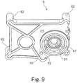
- FIG. 9 shows the cover 6 in a perspective view from below or from the perspective of the distributor housing 5.
- the cover 6 has a bearing opening 47, through which the free end 34 opposite the end of the control shaft 33 can be performed.
- This end is designed as a coupling end 48 and has on its outer periphery an outer toothing 49 which can be coupled to the actuator 3 or brought into operative connection.
- the support projections 42 form on its side opposite the first axial stop 43 side a second axial stop 50, with which the control shaft 33 is supported on the inside of the lid 6.
- a sealing ring 51 is advantageously provided.
- the bearing opening 47 and the coupling end 48 of the control shaft 33 are formed such that the control shaft 33 is mounted radially in the bearing opening 47 and axially on the cover 6.
- the cover 6 on its underside also preferably two rotational stops 52 and 53, which are each formed by an axial projection on the underside of the lid, and which are in the assembled state of the disc valve 2 in the path of movement of the radial projection 46. If the control shaft 33 is actuated by means of the actuator 3, it can be rotated only between the two defined by rotation stops 42 and 43 positions until each of the radial projection 46 against one of Sliding stops 52 or 53 hits.
- the rotary cuffs 52 and 53 may also be formed by a single, correspondingly wide or shaped projection of the cover 6.
- the cover 6 and the distributor housing 5 are formed such that they can be connected to each other only in a certain relative position to each other, so that the lid 6 undergoes a clear alignment on the distributor housing 5.
- the rotation stops 53 and 52 are in known positions with respect to the chambers 55, 56 and with respect to the flow openings 19 and 20.
- the preassembled assembly 30 is first according to FIG. 6 composed. Subsequently, the preassembly assembly is inserted into the distributor housing 5, in which the profile gasket 15 and the gasket 18 are already arranged and aligned according to the axial projection 17, so that the free end 34 of the control shaft 33 engages the bearing seat 21, as in FIG FIG. 2 shown. Subsequently, the lid 6 is pushed with the bearing opening 47 on the coupling end 48 of the control shaft 33 and the control shaft 33 braced due to the first axial stop 43 against the coil spring 41, so that the valve disc 25th is urged spring loaded against the sealing washer 18, so that the valve disc 25 and the sealing washer 18 tightly against each other and an unwanted flow through the disc valve 2 is reliably prevented.
- the lid 6 may, for example, with the distributor housing 5, as, as in FIG. 1 shown, screwed to ensure a permanent connection of the housing 4.
- Valve disc 25 and sealing washer 18 separate or connect, depending on the rotational position of the valve disc 25, the chambers 55 and 56 of the inlet port 7 associated chamber 57, which is bounded by the distributor housing 5, the cover 6 and the valve disc 25 and sealing washer 18.
- the drive unit 3 is mounted on the cover 6 of the disc valve 2.
- the drive unit 3 has a housing 58 in which the electric motor 59 and the transmission 60 are arranged to form a drive device.
- the housing 58 also has a plug connection 61, by means of which the drive unit 3 is electrically contactable.
- the cover 6 of the housing 4 at least three Anschraubdome 62, which protrude in the present embodiment as cylindrical projections perpendicularly from cover 6 parallel to each other.
- a fourth Anschraubdom 62 is provided in the non-visible area.
- the housing 58 has to the Anschraubdomen 62 complementary Anschlußdome 63, which in contrast to the Anschraubdomen 62 have a much shorter axial extent.
- the housing 58 rests on the Anschraubdomen 62, so that the axes of the respective Anschraubdome 62, 63 are aligned.
- the Anschraubdome 62 each have an internal thread into which a screw 64 which is inserted through a through hole of the opposite Anschraubdoms 63, can be screwed to secure the housing 58 to the cover 6 and the housing 4, as in FIG. 1 exemplified for a screw.
- Anschraubdome 63 also differently shaped counter-elements for Anschraubdome 62 may be provided on the housing 58, such as receiving recesses or laterally projecting tabs.
- the housing 58 can be screwed directly onto the screw domes 62 with a housing part.
- the Anschraubdome 62 may be disposed on the housing 58 and the Anschraubdome 63 on the housing 4 or cover 6.
- the size of the Anschraubdome 62 and 63 is according to FIG. 1 chosen such that the housings 58 and 4 are arranged substantially at a distance from each other, so that there is a thermally insulating air gap between them.
- the air gap 66 prevents the drive unit 3 could be heated by the guided through the disc valve 2 and possibly heated medium and thus could be disturbed in its functioning.
- FIG. 10 shows a perspective top view of the cover 6 of the housing 4, the cover 6, the coupling end 48 of the control shaft 38 associated with a splash guard 67.
- the splash guard 67 has a coaxially to the control shaft 33 arranged, the coupling end 48 circumferentially surrounding first Protective wall 68, which is integrally formed with the lid 6.
- the first protective wall 68 has four evenly distributed over its circumference arranged narrow recesses 69.
- the diameter of the protective wall 69 is selected such that it is at a distance from the coupling end 33 of the control shaft 48.
- the height of the protective wall 68 is selected such that it is projected axially from the coupling end 33.
- FIG. 11 shows a sectional view through the valve device 1 according to the section of FIG. 2 , wherein now also the housing 58 of the drive unit 3 is shown, while the disc valve 2 is shown only partially.
- the drive unit has a drive shaft 70, which represents the output shaft of the transmission 60.
- the connection to the transmission 60 and the transmission 60 itself are not shown here for reasons of clarity.
- the drive shaft 70 has at its free, the disc valve 2 facing end or at its coupling end on an axial recess, which has a polygonal shape on its inner surface of the shell, which forms an internal toothing 71.
- the internal toothing 71 is formed complementary to the external toothing 49 of the control shaft 33, so that the internal toothing and the external toothing 49 positively engage with each other and form a positive toothed coupling 76, so that a torque from the drive shaft 70 to the control shaft 33 is preferably transferable without play ,
- the coupling end 48 of the control shaft 33 is mounted axially play in the drive shaft 70.
- the external teeth 49 and the internal teeth 71 together form a coupling device 72, through which the drive shaft 70 and the control shaft 33 are operatively connected to each other for torque transmission.
- the housing 58 of the drive unit 3 has the coupling device 72 associated second protective walls 73 and 74, which are also arranged coaxially to the axis of rotation of the drive shaft 70 and control shaft 33.
- the second protective wall 74 has a diameter which is smaller than the diameter of the first protective wall 68, while the second protective wall 73 has a diameter which is greater than that of the protective wall 68.
- the diameters are chosen such that the first and the second protective walls 68, 73, 74 together form a labyrinth seal 75 which is assigned to the coupling device 72.
- the second protective walls 73, 74 are provided with narrow recesses, which are preferably arranged offset to the recesses 69.
- the recesses 69 and an axial distance between the free end faces of the end walls 68, 73, 74 to the respective opposite housing, cause ventilation and cooling of the coupling device 72.
- the labyrinth seal 75 is also ensured that no splash or other dirt particles in the area the coupling device 72 can pass, so that it is also prevented that moisture in the drive shaft 70 in the drive unit 3 or on the control shaft 33 could get past in the disc valve 2. This ensures that the pumped through the disc valve 2 medium is not contaminated and Moisture can not get into the electrical / electronic components of the drive unit 3.
- the coupling device 72 which is located in the region of the air gap 66, moreover, allows in a simple manner that the disc valve 2 and the drive unit 3 can each be completely pre-assembled before, according to FIG. 1 or 11 be joined together.
- a plug connection between control shaft 33 and drive shaft 70 is made possible in a simple manner, so that only the drive unit 3 has to be plugged onto the disc valve 2 for coupling the shafts with one another.
- This also results in a simple and quick installation of the disc valve device 1.
- the coupling device 72 is disposed between the housings 58 and 4, can also be realized in a simple manner a modular system in which different disc valves 2 with different drive units 3 can be combined are. It does not necessarily have to be disc valves 2 according to the present embodiment, and of course other valve units such as ball valves or the like can be combined with the drive unit 3.
Landscapes
- Engineering & Computer Science (AREA)
- General Engineering & Computer Science (AREA)
- Mechanical Engineering (AREA)
- Physics & Mathematics (AREA)
- Electromagnetism (AREA)
- Fluid Mechanics (AREA)
- General Physics & Mathematics (AREA)
- Lift Valve (AREA)
- Valve Housings (AREA)
- Electrically Driven Valve-Operating Means (AREA)
Description
Die Erfindung betrifft eine Ventileinrichtung gemäss den oberbegrifflichen Merkmalen von Anspruch 1, wie beispielsweise aus Dokument
Ventileinrichtungen werden beispielsweise in Kraftfahrzeugen zur Regulierung von Kühlwasserkreisläufen oder auch bei Getränkeautomaten eingesetzt. Aus der
Die gattungsbildende Offenlegungsschrift
Der Erfindung liegt die Aufgabe zugrunde, eine Ventileinrichtung zu schaffen, die auf einfache und kostengünstige Art und Weise eine verbesserte Verbindung zwischen den Gehäusen bietet.The invention has for its object to provide a valve device which provides a simple and inexpensive way an improved connection between the housings.
Die der Erfindung zugrunde liegende Aufgabe wird durch eine Ventileinrichtung mit den Merkmalen des Anspruchs 1 gelöst. Die erfindungsgemäße Ventileinrichtung, insbesondere Scheibenventileinrichtung, hat den Vorteil, dass das Ventil, insbesondere Scheibenventil, und die Antriebseinheit im Bereich zwischen den Gehäusen miteinander zur Drehmomentübertragung verbunden werden. Dadurch liegt die Koppelstelle von Antriebseinheit zu Ventil/Scheibenventil in einem leicht zugängigen Bereich und erlaubt, dass das Scheibenventil und die Antriebseinheit vollständig vormontiert werden können, bevor sie zusammengeführt werden, um die Ventileinrichtung beziehungsweise Scheibenventileinrichtung zu bilden. Dadurch wird die Montage vereinfacht und es lassen sich auf einfache Art und Weise unterschiedliche Ventile/Scheibenventile mit unterschiedlichen Antriebseinheiten kombinieren, wodurch die Verwendung eines Baukastensystems bei der Montage ermöglicht wird. Die Erfindung zeichnet sich dadurch aus, dass das Scheibenventil eine Steuerwelle und die Antriebseinheit eine mit der Antriebseinrichtung wirkverbundene und mit der Steuerwelle durch eine Koppeleinrichtung wirkverbundene/wirkverbindbare Antriebswelle aufweist, und dass die Koppeleinrichtung zwischen dem ersten und dem zweiten Gehäuse angeordnet ist. Somit ragt sowohl aus dem ersten als auch aus dem zweiten Gehäuse jeweils eine Welle in den Zwischenraum zwischen den beiden Gehäusen, um dort durch die Koppeleinrichtung miteinander wirkverbunden zu werden. Dadurch findet die Drehmomentübertragung von der Antriebseinheit auf das Scheibenventil in dem Spalt zwischen dem ersten und dem zweiten Gehäuse statt, wodurch sich die oben beschriebenen Vorteile ergeben.The object underlying the invention is achieved by a valve device having the features of claim 1. The valve device according to the invention, in particular disk valve device, has the advantage that the valve, in particular disk valve, and the drive unit are connected to each other in the area between the housings for torque transmission. As a result, the coupling point from drive unit to valve / disc valve is in an easily accessible area and allows the disc valve and the drive unit can be completely pre-assembled before they are merged to form the valve device or disc valve device. As a result, the assembly is simplified and it can be combined in a simple manner different valves / disc valves with different drive units, whereby the use of a modular system is made possible during assembly. The invention is characterized in that the disk valve has a control shaft and the drive unit has a drive shaft operatively connected to the drive device and operatively connected to the control shaft by a coupling device, and in that the coupling device is arranged between the first and the second housing. Thus, in each case a shaft protrudes from the first as well as from the second housing into the intermediate space between the two housings in order to be operatively connected to one another there by the coupling device. As a result, the torque transmission from the drive unit to the disk valve takes place in the gap between the first and second housings, resulting in the advantages described above.
Gemäß einer vorteilhaften Weiterbildung der Erfindung ist vorgesehen, dass die Koppeleinrichtung als formschlüssige Kupplung ausgebildet ist. Die formschlüssige Kupplung erlaubt die direkte Drehmomentübertragung von der Steuerwelle auf die Antriebswelle. Zweckmäßigerweise ist die formschlüssige Kupplung in Drehmitnahmerichtung zumindest im Wesentlichen spielfrei ausgebildet, so dass eine genaue Einstellung beziehungsweise Betätigung des Scheibenventils gewährleistet wird. Vorzugsweise ist die formschlüssige Kupplung axial gesehen spielbehaftet ausgebildet, um temperaturbedingte oder toleranzbedingte Längenunterschiede der beiden Wellen und/oder der Gehäuse kompensieren zu können. Alternativ ist es auch denkbar, die Koppeleinrichtung als kraftschlüssige Kupplung auszubilden.According to an advantageous embodiment of the invention it is provided that the coupling device is designed as a positive coupling. The positive coupling allows the direct transmission of torque from the control shaft to the drive shaft. Conveniently, the positive coupling is formed in the rotational direction at least substantially free of play, so that a precise adjustment or actuation of the disc valve is ensured. Preferably, the form-fitting coupling is formed with play in axial direction in order to be able to compensate for temperature-related or tolerance-related differences in length of the two shafts and / or the housing. Alternatively, it is also conceivable to form the coupling device as a non-positive coupling.
Besonders bevorzugt ist die Koppeleinrichtung als Zahn- oder Klauenkupplung ausgebildet. Dabei kann die Koppeleinrichtung durch auf die Antriebswelle und die Steuerwelle aufsetzbare Drehmitnahmeelemente oder integral durch die Antriebswelle und die Steuerwelle selbst einstückig ausgebildet sein. Bei der Zahn- oder Klauenkupplung können die Zähne beziehungsweise Klauen gemäß einer Ausführungsform an der Stirnseite der jeweiligen Welle angeordnet sein.Particularly preferably, the coupling device is designed as a tooth or dog clutch. In this case, the coupling device can be formed by integrally formed on the drive shaft and the control shaft rotational drive elements or integrally by the drive shaft and the control shaft itself. In the tooth or dog clutch, the teeth or claws can be arranged according to an embodiment on the end face of the respective shaft.
Gemäß einer bevorzugten Ausführungsform der Erfindung ist vorgesehen, dass die Koppeleinrichtung von einer Außenverzahnung der Steuerwelle und einer mit der Außenverzahnung in Eingriff stehenden Innenverzahnung der Antriebswelle gebildet wird. Die Steuerwelle ragt somit bereichsweise mit ihrem freien Ende in einen Hohlwellenabschnitt der Antriebswelle hinein, um dort mittels Außenverzahnung und Innenverzahnung die Drehmomentübertragung zu bewirken. Die Koppeleinrichtung wird hierbei durch Antriebswelle und Steuerwelle selbst gebildet. Natürlich ist auch eine umgekehrte Ausbildung möglich, bei welcher die Außenverzahnung an der Antriebswelle und die Innenverzahnung an der Steuerwelle vorgesehen ist. Allgemein lässt sich sagen, dass die Antriebswelle und die Steuerwelle bevorzugt durch zueinander komplementäre Polygonformen miteinander formschlüssig zur Drehmomentübertragung verbunden sind.According to a preferred embodiment of the invention, it is provided that the coupling device is formed by an external toothing of the control shaft and an internal toothing of the drive shaft which is in engagement with the external toothing. The control shaft thus protrudes partially with its free end in a hollow shaft portion of the drive shaft in order to effect the torque transmission there by external teeth and internal teeth. The coupling device is formed by drive shaft and control shaft itself. Of course, a reverse training is possible in which the external toothing is provided on the drive shaft and the internal toothing on the control shaft. In general, it can be said that the drive shaft and the control shaft are preferably connected to one another in a form-fitting manner for torque transmission by mutually complementary polygonal shapes.
Erfindungsgemäß ist vorgesehen, dass der Koppeleinrichtung ein Spritzschutz zugeordnet ist. Der Spritzschutz verhindert, dass im Betrieb Feuchtigkeit, beispielsweise Spritzwasser, zur beziehungsweise auf die Koppeleinrichtung gelangt und von dieser weiter in die Antriebseinheit oder in das Scheibenventil. Durch den Spritzschutz wird die Lebensdauer der Ventileinrichtung insgesamt erhöht.According to the invention it is provided that the coupling device is associated with a splash guard. The splash guard prevents moisture, for example splash water, from reaching the coupling device during operation and from the latter into the drive unit or into the disk valve. Through the splash guard, the life of the valve device is increased overall.
Erfindungsgemäß ist vorgesehen, dass der Spritzschutz wenigstens eine die Koppeleinrichtung umfangsseitig zumindest im Wesentlichen umgebende erste Schutzwand aufweist. Diese Schutzwand kann vollständig durchgehend oder mit einer oder mehreren Aussparungen beziehungsweise Unterbrechungen ausgebildet sein, die insbesondere zur Belüftung und Kühlung der Koppeleinrichtung dienen. Vorzugsweise erstreckt sich die Schutzwand derart zwischen den beiden Gehäusen, dass sie von einem Gehäuse zumindest im Wesentlichen bis zum anderen Gehäuse reicht. Die Aussparungen in der Schutzwand dienen bevorzugt auch der Entwässerung im Falle einer Bauteilleckage des Scheibenventils. Bei einem Fehlerfall beziehungsweise Defekt oder auch wenn aufgrund extremer Systemzustände eine kurzzeitige Leckage auftritt, kann durch die Aussparungen Flüssigkeit nach außen entweichen, so dass die Antriebseinheit vor aus dem Ventil austretender Flüssigkeit geschützt ist.According to the invention, it is provided that the splash guard has at least one first protective wall surrounding the coupling device at least substantially circumferentially. This protective wall may be formed completely continuous or with one or more recesses or interruptions, which are used in particular for ventilation and cooling of the coupling device. Preferably, the protective wall extends between the so both housings that it extends from one housing at least substantially to the other housing. The recesses in the protective wall preferably also serve for dewatering in the event of a component leakage of the disk valve. In the case of an error or defect or even if due to extreme system conditions, a brief leakage occurs, liquid can escape through the recesses to the outside, so that the drive unit is protected from exiting the valve fluid.
Erfindungsgemäß ist vorgesehen, dass der Spritzschutz wenigstens eine die Koppeleinrichtung umfangsseitig zumindest im Wesentlichen umgebende zweite Schutzwand aufweist, die einen größeren oder kleineren Durchmesser als die erste Schutzwand aufweist, um zusammen mit der ersten Schutzwand eine Labyrinthdichtung für die Koppeleinrichtung zu bilden. Auch die zweite Schutzwand ist dabei vorzugsweise mit einer oder mehreren Aussparungen beziehungsweise Unterbrechungen zur Belüftung oder Kühlung der Koppeleinrichtung ausgebildet. Besonders bevorzugt sind die Aussparungen der ersten Schutzwand und der zweiten Schutzwand versetzt zueinander angeordnet, um einen vollumfänglichen Spritzschutz zu gewährleisten. Durch die unterschiedlichen Durchmesser werden die erste und die zweite Schutzwand bei einer Montage ineinander gesteckt, wozu sie zweckmäßigerweise koaxial zueinander im montierten Zustand des Gehäuses angeordnet sind.According to the invention, the splash guard has at least one second protective wall surrounding the coupling device at least substantially, which has a larger or smaller diameter than the first protective wall in order to form a labyrinth seal for the coupling device together with the first protective wall. The second protective wall is preferably formed with one or more recesses or interruptions for ventilation or cooling of the coupling device. Particularly preferably, the recesses of the first protective wall and the second protective wall are arranged offset from one another to ensure a full splash protection. Due to the different diameters, the first and the second protective wall are inserted into one another during assembly, for which purpose they are expediently mounted coaxially with one another Condition of the housing are arranged.
Durch die unterschiedlichen Durchmesser wird dabei vorteilhafterweise ein Zwischenraum zwischen den Schutzwänden gebildet, der insbesondere zur Entwässerung genutzt werden kann. Unabhängig davon, wie das Ventil bezüglich der Antriebseinheit montiert wird, also im Wesentlichen unabhängig von der Drehwinkelposition von Ventil zur Antriebseinheit, wird somit eine Entwässerung nach außen hin zu jeder Zeit gewährleistet.Due to the different diameters, a gap between the protective walls is advantageously formed, which can be used in particular for drainage. Regardless of how the valve is mounted with respect to the drive unit, that is, substantially independent of the rotational angle position of the valve to the drive unit, thus ensuring a drainage to the outside at any time.
Erfindungsgemäß ist vorgesehen, dass die erste Schutzwand einstückig mit dem ersten Gehäuse und die zweite Schutzwand einstückig mit dem zweiten Gehäuse ausgebildet ist. Dadurch wird durch Zusammenführen der beiden Gehäuse die Labyrinthdichtung mittels der beiden Schutzwände hergestellt. Die Schutzwände sind dabei bevorzugt an ihren jeweiligen freien Stirnseiten zumindest abschnittsweise beabstandet zu dem jeweils gegenüberliegenden Gehäuse angeordnet beziehungsweise ausgebildet, um eine zusätzliche Lüftung/Kühlung zu gewährleisten, und um insbesondere eine überbestimmte Lagerung der Gehäuse aneinander zu vermeiden.According to the invention, it is provided that the first protective wall is formed integrally with the first housing and the second protective wall is formed integrally with the second housing. As a result, the labyrinth seal is produced by means of the two protective walls by merging the two housings. The protective walls are preferably arranged at their respective free end sides at least partially spaced from the respective opposite housing or formed to ensure additional ventilation / cooling, and in particular to avoid over-determined storage of the housing to each other.
Erfindungsgemäß ist vorgesehen, dass das erste und/oder das zweite Gehäuse wenigstens einen Abstandhalter aufweist, der insbesondere als Anschraubdom ausgebildet ist. Die Abstandhalter sichern den Abstand zwischen den beiden Gehäusen und die Positionierung der Wellenenden von Antriebswelle und Steuerwelle zueinander. Zumindest einer der Abstandhalter kann dabei auch durch den Spritzschutz beziehungsweise durch eine der Schutzwände gebildet sein. Durch die bevorzugte Ausbildung der Abstandshalter jeweils als Anschraubdom, bieten die Abstandhalter gleichzeitig die Befestigungseinrichtung zum Befestigen der beiden Gehäuse aneinander. Der jeweilige Anschraubdom zeichnet sich durch ein Innengewinde aus, das einstückig von dem Anschraubdom oder durch ein in den jeweiligen Anschraubdom eingesetztes Gewindeelement gebildet wird, und in welches eine Schraube zur Befestigung des einen Gehäuses an dem anderen Gehäuse eingeschraubt werden kann.According to the invention, it is provided that the first and / or the second housing has at least one spacer, which is designed in particular as a screw-on dome. The spacers secure the distance between the two housings and the positioning of the shaft ends of the drive shaft and control shaft to each other. At least one of the spacers can also be formed by the splash guard or by one of the protective walls. Due to the preferred embodiment of the spacers in each case as a screw-on dome, the spacers simultaneously provide the fastening device for fastening the two housings together. The respective Anschraubdom is characterized by an internal thread, which is integrally formed by the Anschraubdom or by an inserted into the respective Anschraubdom threaded member, and in which a screw for fixing the one housing to the other housing can be screwed.
Im Folgenden soll die Erfindung anhand der Zeichnungen näher erläutert werden. Dazu zeigen:
- Figur 1
- eine Scheibenventileinrichtung in einer perspektivischen Darstellung,
Figur 2- ein Scheibenventil der Scheibenventileinrichtung in einer Längsschnittdarstellung,
Figur 3- das Scheibenventil in einer Querschnittsdarstellung,
- Figuren 4A und 4B
- eine Dichtscheibe des Scheibenventils in unterschiedlichen perspektivischen Darstellungen,
Figur 5- eine mit der Dichtscheibe zusammenwirkende Ventilscheibe in einer perspektivischen Darstellung,
Figur 6- eine Vormontagebaugruppe des Scheibenventils in einer perspektivischen Darstellung,
- Figuren 7A und 7B
- eine Verdrehsicherung des Scheibenventils in unterschiedlichen Darstellungen,
Figur 8- eine Arretiervorrichtung der Vormontagebaugruppe,
Figur 9- einen Deckel des Scheibenventils in einer perspektivischen Unteransicht,
Figur 10- den Deckel des Scheibenventils in einer perspektivischen Draufsicht und
Figur 11- einen Teil der Scheibenventileinrichtung in einer Längsschnittdarstellung.
- FIG. 1
- a disc valve device in a perspective view,
- FIG. 2
- a disc valve of the disc valve device in a longitudinal sectional view,
- FIG. 3
- the disk valve in a cross-sectional view,
- FIGS. 4A and 4B
- a sealing disc of the disc valve in different perspective views,
- FIG. 5
- a cooperating with the sealing disc valve disc in a perspective view,
- FIG. 6
- a pre-assembly of the disc valve in a perspective view,
- FIGS. 7A and 7B
- a rotation of the disc valve in different representations,
- FIG. 8
- a locking device of the pre-assembly,
- FIG. 9
- a lid of the disc valve in a perspective bottom view,
- FIG. 10
- the lid of the disc valve in a perspective plan view and
- FIG. 11
- a part of the disc valve device in a longitudinal sectional view.
Das Scheibenventil 2 weist ein Gehäuse 4 auf, welches von einem Verteilergehäuse 5 und einem Deckel 6 gebildet wird. Das Verteilergehäuse 5 weist drei Anschlüsse auf, von denen einer als Zulaufanschluss 7, und die beiden anderen als Ablaufanschlüsse 8 beziehungsweise 9 ausgebildet sind. Außerdem weist das Verteilergehäuse 5 eine Haltevorrichtung 10 zum Befestigen der Ventileinrichtung 1, beispielsweise an einer Karosserie eines Kraftfahrzeugs, auf.The
An dem Deckel 6 ist die Antriebseinheit 3 montiert, die insbesondere als elektromotorischer Stellantrieb ausgebildet ist und hierzu einen nicht näher dargestellten Elektromotor 59 sowie ein mit dem Elektromotor 59 wirkverbundenes Getriebe 60 mit einer Antriebswelle 70 aufweist, die mit einer Steuerwelle des Scheibenventils 2 koppelbar ist, um ein an dem Zulaufanschluss 7 bereitgestelltes Medium auf die Ablaufanschlüsse 8, 9 wunschgemäß zu verteilen. Hierauf soll weiter unten näher eingegangen werden.On the
während ein Großteil des Zwischenbodens 14 von den verbleibenden 120° durch die Trennwand 13 gebildet wird.
while a majority of the intermediate bottom 14 is formed by the remaining 120 ° through the
Auf dem Zwischenboden 14 liegt eine Profildichtung 15 auf, deren Kontur im Wesentlichen der Kontur des Zwischenbodens 14 entspricht und elastisch verformbar ausgebildet ist. Die Profildichtung 15 weist einen zusätzlichen Durchbruch 16 auf, durch welchen ein Axialvorsprung 17 des Zwischenbodens 14 zum Bilden einer Verdrehsicherung 24 für die Profildichtung 15 hindurch ragt. Dabei ist die Höhe des Axialvorsprungs 17 derart gewählt, dass sie über die Profildichtung 15 hinaus vorsteht.On the intermediate bottom 14 is a
Vorteilhafterweise sind derartige Anphasungen 22 auch auf der Rückseite der Dichtscheibe 18 im Bereich der Durchströmungsöffnungen 19, 20 vorgesehen, wie in
Die Steuerwelle 33 ragt mit einem freien Ende 34 durch den Durchbruch 28 der Ventilscheibe 25 hindurch, um wie in
Beabstandet zu dem freien Ende 34 weist die Steuerwelle 33, wie in
Das Federelement 32 ist im vorliegenden Ausführungsbeispiel als Schraubenfeder 41 ausgebildet. Die Schraubenfeder 41 ist zwischen den seitlich vorstehenden Stützfüßen 40 des Zwischenelements 31 und mehreren radial vorstehenden Stützvorsprüngen 42 der Steuerwelle 33 axial gehalten. Die Stützvorsprünge 42 sind gleichmäßig über den Umfang der Steuerwelle 33 verteilt angeordnet und einstückig mit dieser ausgebildet. Vorzugsweise gehen zwei gegenüberliegende Stützvorsprünge 42 dabei in die seitlichen Vorsprünge 35 und 26 über. Die Stützvorsprünge 42 bilden zusammen einen ersten Axialanschlag 43 für die Schraubenfeder 41, während die Stützfüße 40 einen zweiten Axialanschlag für die Schraubenfeder 41 bilden. Bei der Vormontage wird die Schraubenfeder 41 auf die Steuerwelle 33 bis an den ersten Axialanschlag 43 aufgeschoben, anschließend wird das Zwischenelement 31 wie zuvor beschrieben auf die Steuerwelle 33 aufgeschoben und zuletzt die Ventilscheibe 25, so dass die Füße 40 in die Aussparungen 27 eingreifen.The
Zur Arretierung der Vormontagebaugruppe 30 weist das Zwischenelement 31 mehrere elastisch verformbare Klemmrippen 45 auf, die sich parallel zur Längserstreckung des Scheibenventils 2 beziehungsweise zur Drehachse der Steuerwelle 33 stegförmig erstrecken, wie in
Weiterhin ist bevorzugt vorgesehen, dass die Steuerwelle 33 auf der dem Federelement 41 abgewandten Seite der Stützvorsprünge 42 einen Radialvorsprung 46 aufweist, wie in
Wie aus
Der Deckel 6 sowie das Verteilergehäuse 5 sind derart ausgebildet, dass sie nur in einer bestimmten Relativposition zueinander miteinander verbunden werden können, so dass der Deckel 6 eine eindeutige Ausrichtung auf dem Verteilergehäuse 5 erfährt. Dadurch liegen die Drehanschläge 53 und 52 auf bekannten Positionen bezüglich der Kammern 55, 56 beziehungsweise bezüglich der Durchströmungsöffnungen 19 und 20. Durch die drehfeste Verbindung der Ventilscheibe 25 mit der Steuerwelle 33 sowie die gehäusefeste Lage der Dichtscheibe 18, und die bekannte Anordnung des Radialvorsprungs sowie der Drehanschläge 52, 53, kann somit bei der Montage mittels des Stellantriebs das Scheibenventil 2 in eine eindeutige Ausgangsstellung verbracht werden, ohne dass dies anhand eines tatsächlich eingestellten Volumenstroms durch das Scheibenventil 2 hindurch verifiziert werden müsste.The
Bei der Montage wird zunächst die Vormontagebaugruppe 30 gemäß
Wie mit Bezug auf
Wie aus
Mit den Anschlussdomen 63 liegt das Gehäuse 58 auf den Anschraubdomen 62 auf, so dass die Achsen der jeweiligen Anschraubdome 62, 63 miteinander fluchten. Die Anschraubdome 62 weisen jeweils ein Innengewinde auf, in das eine Schraube 64, die durch eine Durchgangsöffnung des gegenüberliegenden Anschraubdoms 63 eingeführt ist, einschraubbar ist, um das Gehäuse 58 an dem Deckel 6 beziehungsweise an dem Gehäuse 4 zu befestigen, wie in
Die Größe der Anschraubdome 62 und 63 ist gemäß
Wie aus
Das Gehäuse 58 der Antriebseinheit 3 weist der Koppeleinrichtung 72 zugeordnete zweite Schutzwände 73 und 74 auf, die ebenfalls koaxial zur Drehachse von Antriebswelle 70 und Steuerwelle 33 angeordnet sind. Dabei weist die zweite Schutzwand 74 einen Durchmesser auf, der kleiner ist als der Durchmesser der ersten Schutzwand 68, während die zweite Schutzwand 73 einen Durchmesser aufweist, der größer ist als der der Schutzwand 68. Dadurch wird zwischen den Schutzwänden 73 und 74 eine kreisringförmige Aufnahmevertiefung gebildet, in welche die erste Schutzwand 68 eindringt, wenn das Gehäuse 58 auf dem Gehäuse 4 montiert wird, wie in
dass die ersten und die zweiten Schutzwände 68, 73, 74 zusammen eine Labyrinthdichtung 75 bilden, die der Koppeleinrichtung 72 zugeordnet ist. Zweckmäßigerweise sind auch die zweiten Schutzwände 73, 74 mit schmalen Aussparungen versehen, die bevorzugt versetzt zu den Aussparungen 69 angeordnet sind. Die Aussparungen 69 sowie ein axialer Abstand zwischen den freien Stirnseiten der Stirnwände 68, 73, 74 zu dem jeweils gegenüberliegenden Gehäuse, bewirken eine Belüftung und Kühlung der Koppeleinrichtung 72. Durch die Labyrinthdichtung 75 wird zudem gewährleistet, dass kein Spritzwasser oder sonstige Schmutzpartikel in den Bereich der Koppeleinrichtung 72 gelangen können, so dass auch verhindert wird, dass Feuchtigkeit im Bereich der Antriebswelle 70 in die Antriebseinheit 3 oder an der Steuerwelle 33 vorbei in das Scheibenventil 2 gelangen könnte. Dadurch wird gewährleistet, dass das durch das Scheibenventil 2 geförderte Medium nicht verunreinigt wird und Feuchtigkeit nicht bis in die elektrischen/elektronischen Bestandteile der Antriebseinheit 3 gelangen kann.The
the first and the second
Die Koppeleinrichtung 72, die in dem Bereich des Luftspalts 66 liegt, erlaubt darüber hinaus auf einfache Art und Weise, dass das Scheibenventil 2 und die Antriebseinheit 3 jeweils vollständig vormontiert werden können, bevor sie gemäß
Claims (7)
- A valve arrangement (1) having a valve, in particular a disk valve (2), which has a first housing (4) with several connections (7-9) for a fluid and/or gaseous medium, and with a drive unit (3), which has a second housing (58) with a drive mechanism (59, 60) arranged therein, wherein the housings (4, 58) are at least essentially spaced apart from one another, so that there is a thermally insulating air gap (66) between them, wherein the valve (2) has a control shaft (33) and the drive unit (3) a drive shaft (70) that is operatively connected to the drive mechanism (59, 60) and operatively connected/operatively connectable to the control shaft (33) by means of a coupling device (72), wherein the coupling device (72) is arranged between the first and the second housing (4, 58), and wherein a splash guard (67) is allocated to the coupling device (72), which splash guard (67) at least has one first protective panel (68) at least essentially circumferentially surrounding the coupling device (72), characterized in that the splash guard (67) has at least one second protective panel (73, 74) circumferentially surrounding at least essentially the coupling device (72), which second protective panel (73, 74) has a larger or smaller diameter than the first protective panel (68) in order to form a labyrinth seal (75) for the coupling device (72) together with the first protective panel (68), wherein the at least one first protective panel (68) is configured in one piece with the first housing (4), and that the at least one second protective panel (73, 74) is configured in one piece with the second housing (58), and wherein an axial distance is provided between the free front sides of the front panels (68, 73, 74) to the respectively opposite housing (4, 58), and wherein the first and/or the second housing (4, 58) has at least one spacer which in particular is configured as a screw dome (62, 63).
- The valve arrangement according to claim 1, characterized in that the coupling device (72) is configured as a positive coupling (76).
- A valve arrangement according to any one of the preceding claims, characterized in that the coupling device (72) is configured as a gear coupling (76) or as a claw coupling.
- A valve arrangement according to any one of the preceding claims, characterized in that the coupling device (72) is formed by an external gearing (49) of the control shaft (33) and by an internal gearing (71) of the drive shaft (70) engaging in the external gearing (49).
- A valve arrangement according to any one of the preceding claims, characterized in that the first protective panel (68) has one or more recesses (69).
- A valve arrangement according to any one of the preceding claims, characterized in that the second protective panel (73, 74) has one or more recesses.
- A valve arrangement according to claims 5 and 6, characterized in that the recesses (69) of the first protective panel (68) and of the second protective panel (73, 74) are offset with respect to one another.
Applications Claiming Priority (2)
| Application Number | Priority Date | Filing Date | Title |
|---|---|---|---|
| DE102012022213.0A DE102012022213B4 (en) | 2012-11-07 | 2012-11-07 | valve means |
| PCT/EP2013/073221 WO2014072376A1 (en) | 2012-11-07 | 2013-11-07 | Valve device |
Publications (2)
| Publication Number | Publication Date |
|---|---|
| EP2917620A1 EP2917620A1 (en) | 2015-09-16 |
| EP2917620B1 true EP2917620B1 (en) | 2017-01-04 |
Family
ID=49551603
Family Applications (1)
| Application Number | Title | Priority Date | Filing Date |
|---|---|---|---|
| EP13786672.9A Active EP2917620B1 (en) | 2012-11-07 | 2013-11-07 | Valve device |
Country Status (4)
| Country | Link |
|---|---|
| US (1) | US9410628B2 (en) |
| EP (1) | EP2917620B1 (en) |
| DE (2) | DE102012022213B4 (en) |
| WO (1) | WO2014072376A1 (en) |
Cited By (2)
| Publication number | Priority date | Publication date | Assignee | Title |
|---|---|---|---|---|
| WO2023237235A1 (en) | 2022-06-10 | 2023-12-14 | Voss Automotive Gmbh | Multi-way valve |
| WO2024085463A1 (en) * | 2022-10-19 | 2024-04-25 | Hanon Systems | Disc coolant valve with self-leveling flow control disc |
Families Citing this family (13)
| Publication number | Priority date | Publication date | Assignee | Title |
|---|---|---|---|---|
| US10920894B2 (en) * | 2016-06-08 | 2021-02-16 | Hangzhou Sanhua Research Institute Co., Ltd. | Flow control device and method for manufacturing the same |
| WO2018010525A1 (en) * | 2016-07-12 | 2018-01-18 | 杭州三花研究院有限公司 | Flow control apparatus |
| CN107606236B (en) | 2016-07-12 | 2020-06-26 | 杭州三花研究院有限公司 | Flow rate control device |
| DE202016004426U1 (en) | 2016-07-20 | 2017-10-23 | Voss Automotive Gmbh | Assembly unit with drive unit and mass flow control or valve unit and transmission unit for transmitting torques and rotations from a drive unit to a mass flow adjustment of a mass flow control or valve unit |
| DE202016004427U1 (en) | 2016-07-20 | 2017-10-23 | Voss Automotive Gmbh | Mass flow control or valve unit |
| DE102017200573A1 (en) * | 2017-01-16 | 2018-07-19 | Continental Automotive Gmbh | valve unit |
| JP6945859B2 (en) * | 2018-06-04 | 2021-10-06 | 株式会社不二工機 | Flow switching valve |
| JP6737380B1 (en) * | 2019-06-11 | 2020-08-05 | 株式会社デンソー | Valve device |
| DE102019218107A1 (en) * | 2019-11-22 | 2021-05-27 | Mack & Schneider Gmbh | Rotary valve |
| US11585451B2 (en) | 2021-06-08 | 2023-02-21 | Robert Bosch Llc | Rotary disc valve |
| US11572957B2 (en) | 2021-06-08 | 2023-02-07 | Robert Bosch Gmbh | Rotary disc valve |
| CN113531158B (en) * | 2021-07-30 | 2023-03-10 | 九通集团有限公司 | Three-way disc valve for polycrystalline silicon |
| US20230184338A1 (en) * | 2021-12-15 | 2023-06-15 | Robert Bosch Gmbh | Rotary Disc Valve |
Family Cites Families (20)
| Publication number | Priority date | Publication date | Assignee | Title |
|---|---|---|---|---|
| US1842788A (en) * | 1928-11-28 | 1932-01-26 | Kramer Bernhard | Fluid controlling device |
| US3173650A (en) * | 1962-03-05 | 1965-03-16 | Crane Co | Butterfly valve seat construction |
| DE2438875C3 (en) * | 1973-09-24 | 1982-04-01 | Kutzner, Luitpold, Dipl.-Ing., 8000 München | Shut-off device for installation in the exhaust pipe of fireplaces |
| DE2530347C3 (en) * | 1975-07-08 | 1979-11-15 | Klein, Schanzlin & Becker Ag, 6710 Frankenthal | Bracket for an actuator |
| US4022424A (en) * | 1975-09-29 | 1977-05-10 | General Electric Company | Shaft bearing and seals for butterfly valves |
| US4046350A (en) * | 1976-07-26 | 1977-09-06 | The Parker & Harper Manufacturing Company, Inc. | Power actuated valve |
| FR2463349A1 (en) * | 1979-08-07 | 1981-02-20 | Gachot Jean | Chair for remote control actuator of rotary ball valve - has 'H' shape with cover plate bolts to valve and located ball drive shaft with axial float |
| DE3416970A1 (en) * | 1984-05-08 | 1985-11-14 | Hans 8025 Unterhaching Lechner | Control valve |
| FR2634853B1 (en) * | 1988-07-29 | 1990-10-19 | Mecafrance Sa | IMPROVEMENTS TO VALVE SEALING DEVICES |
| DE9212236U1 (en) * | 1992-09-10 | 1993-05-27 | Tisch, Walter, 8900 Augsburg, De | |
| US5676472A (en) * | 1995-07-10 | 1997-10-14 | Smart Machines | Rotary labyrinth seal |
| US5950576A (en) | 1998-06-30 | 1999-09-14 | Siemens Canada Limited | Proportional coolant valve |
| WO2002059515A1 (en) * | 2001-01-26 | 2002-08-01 | Yamatake Corporation | Actuator and valve device with the actuator |
| DE10323661A1 (en) * | 2003-05-14 | 2004-12-02 | Hirner, Edmund, Dipl.-Ing.(Fh) | Automatic liquid, especially water, distributor for use in showers, etc., has a supply with a rotating single hole disk that can connects to one or more outlet holes serially, or partially in parallel, by use of a control actuator |
| JP4285267B2 (en) * | 2004-02-19 | 2009-06-24 | 株式会社デンソー | Exhaust gas recirculation device |
| WO2005116423A1 (en) * | 2004-05-31 | 2005-12-08 | Aisan Kogyo Kabushiki Kaisha | Molding method for throttle body and throttle body |
| US7556239B2 (en) * | 2007-01-11 | 2009-07-07 | Colonial Engineering, Inc. | Slow close valve |
| SE529968C2 (en) * | 2007-03-05 | 2008-01-15 | Esbe Ab | Multi-way valve for actuator comprises body, head from which outer end of rotary stem of valve projects, connection means, valve stem and actuator |
| DE102009024361B4 (en) * | 2009-06-04 | 2021-10-21 | Illinois Tool Works Inc. | Valve arrangement for an internal combustion engine |
| GB0910082D0 (en) * | 2009-06-11 | 2009-07-22 | Norgren Ltd C A | Two-part valve |
-
2012
- 2012-11-07 DE DE102012022213.0A patent/DE102012022213B4/en active Active
- 2012-11-07 DE DE202012012980.5U patent/DE202012012980U1/en not_active Expired - Lifetime
-
2013
- 2013-11-07 WO PCT/EP2013/073221 patent/WO2014072376A1/en active Application Filing
- 2013-11-07 EP EP13786672.9A patent/EP2917620B1/en active Active
-
2015
- 2015-05-07 US US14/706,127 patent/US9410628B2/en active Active
Cited By (2)
| Publication number | Priority date | Publication date | Assignee | Title |
|---|---|---|---|---|
| WO2023237235A1 (en) | 2022-06-10 | 2023-12-14 | Voss Automotive Gmbh | Multi-way valve |
| WO2024085463A1 (en) * | 2022-10-19 | 2024-04-25 | Hanon Systems | Disc coolant valve with self-leveling flow control disc |
Also Published As
| Publication number | Publication date |
|---|---|
| US9410628B2 (en) | 2016-08-09 |
| WO2014072376A1 (en) | 2014-05-15 |
| EP2917620A1 (en) | 2015-09-16 |
| DE202012012980U1 (en) | 2014-06-18 |
| DE102012022213A1 (en) | 2014-05-22 |
| DE102012022213B4 (en) | 2019-04-25 |
| US20150233476A1 (en) | 2015-08-20 |
Similar Documents
| Publication | Publication Date | Title |
|---|---|---|
| EP2917620B1 (en) | Valve device | |
| EP2917619B1 (en) | Disc valve | |
| EP2917621B1 (en) | Disc valve | |
| DE102015207231B4 (en) | filtering device | |
| EP2084439B1 (en) | Rotary slide valve, in particular for a coolant circuit, which has a plurality of branches, of an internal combustion engine; electromechanical assembly | |
| DE102006054041B3 (en) | Regulating device for an internal combustion engine | |
| EP2851596B1 (en) | Wall feedthrough element for a fluid line and wall feedthrough | |
| DE102007019064B3 (en) | Rotary slide valve, particularly for coolant circuit, has device that is provided to couple cross section adjustment members to one another, which generates rotational angle difference between cross section adjustment members | |
| EP3207295B1 (en) | Valve device | |
| DE102013209053B4 (en) | Camshaft adjuster with a spring mount and a return spring | |
| WO2012022522A1 (en) | Valve of a piston pump with a closing body | |
| DE102013114625A1 (en) | Camshaft adjusting device, internal combustion engine and assembly process | |
| EP3227540B1 (en) | Flap device for an internal combustion engine | |
| EP3596367A1 (en) | Rotary slide valve for use in the automotive field | |
| EP3126651B1 (en) | Flap device for an internal combustion engine | |
| DE102014117675B4 (en) | Valve device for an internal combustion engine | |
| DE10356908A1 (en) | Motor vehicle camshaft adjustment device has a rotor and a stator with the stator axially fixed to a cover by an arrangement of form-fit and counter form-fit elements | |
| EP4062088B1 (en) | Rotary valve | |
| EP3463612A1 (en) | Filter device | |
| DE3434509A1 (en) | Through-flow switch for fluids |
Legal Events
| Date | Code | Title | Description |
|---|---|---|---|
| PUAI | Public reference made under article 153(3) epc to a published international application that has entered the european phase |
Free format text: ORIGINAL CODE: 0009012 |
|
| 17P | Request for examination filed |
Effective date: 20150608 |
|
| AK | Designated contracting states |
Kind code of ref document: A1 Designated state(s): AL AT BE BG CH CY CZ DE DK EE ES FI FR GB GR HR HU IE IS IT LI LT LU LV MC MK MT NL NO PL PT RO RS SE SI SK SM TR |
|
| AX | Request for extension of the european patent |
Extension state: BA ME |
|
| DAX | Request for extension of the european patent (deleted) | ||
| GRAP | Despatch of communication of intention to grant a patent |
Free format text: ORIGINAL CODE: EPIDOSNIGR1 |
|
| INTG | Intention to grant announced |
Effective date: 20160705 |
|
| GRAS | Grant fee paid |
Free format text: ORIGINAL CODE: EPIDOSNIGR3 |
|
| GRAA | (expected) grant |
Free format text: ORIGINAL CODE: 0009210 |
|
| AK | Designated contracting states |
Kind code of ref document: B1 Designated state(s): AL AT BE BG CH CY CZ DE DK EE ES FI FR GB GR HR HU IE IS IT LI LT LU LV MC MK MT NL NO PL PT RO RS SE SI SK SM TR |
|
| REG | Reference to a national code |
Ref country code: GB Ref legal event code: FG4D Free format text: NOT ENGLISH |
|
| REG | Reference to a national code |
Ref country code: CH Ref legal event code: EP |
|
| REG | Reference to a national code |
Ref country code: AT Ref legal event code: REF Ref document number: 859579 Country of ref document: AT Kind code of ref document: T Effective date: 20170115 |
|
| REG | Reference to a national code |
Ref country code: IE Ref legal event code: FG4D Free format text: LANGUAGE OF EP DOCUMENT: GERMAN |
|
| REG | Reference to a national code |
Ref country code: DE Ref legal event code: R096 Ref document number: 502013006003 Country of ref document: DE |
|
| REG | Reference to a national code |
Ref country code: LT Ref legal event code: MG4D Ref country code: NL Ref legal event code: MP Effective date: 20170104 |
|
| PG25 | Lapsed in a contracting state [announced via postgrant information from national office to epo] |
Ref country code: NL Free format text: LAPSE BECAUSE OF FAILURE TO SUBMIT A TRANSLATION OF THE DESCRIPTION OR TO PAY THE FEE WITHIN THE PRESCRIBED TIME-LIMIT Effective date: 20170104 |
|
| PG25 | Lapsed in a contracting state [announced via postgrant information from national office to epo] |
Ref country code: LT Free format text: LAPSE BECAUSE OF FAILURE TO SUBMIT A TRANSLATION OF THE DESCRIPTION OR TO PAY THE FEE WITHIN THE PRESCRIBED TIME-LIMIT Effective date: 20170104 Ref country code: HR Free format text: LAPSE BECAUSE OF FAILURE TO SUBMIT A TRANSLATION OF THE DESCRIPTION OR TO PAY THE FEE WITHIN THE PRESCRIBED TIME-LIMIT Effective date: 20170104 Ref country code: FI Free format text: LAPSE BECAUSE OF FAILURE TO SUBMIT A TRANSLATION OF THE DESCRIPTION OR TO PAY THE FEE WITHIN THE PRESCRIBED TIME-LIMIT Effective date: 20170104 Ref country code: GR Free format text: LAPSE BECAUSE OF FAILURE TO SUBMIT A TRANSLATION OF THE DESCRIPTION OR TO PAY THE FEE WITHIN THE PRESCRIBED TIME-LIMIT Effective date: 20170405 Ref country code: IS Free format text: LAPSE BECAUSE OF FAILURE TO SUBMIT A TRANSLATION OF THE DESCRIPTION OR TO PAY THE FEE WITHIN THE PRESCRIBED TIME-LIMIT Effective date: 20170504 Ref country code: NO Free format text: LAPSE BECAUSE OF FAILURE TO SUBMIT A TRANSLATION OF THE DESCRIPTION OR TO PAY THE FEE WITHIN THE PRESCRIBED TIME-LIMIT Effective date: 20170404 |
|
| PG25 | Lapsed in a contracting state [announced via postgrant information from national office to epo] |
Ref country code: BG Free format text: LAPSE BECAUSE OF FAILURE TO SUBMIT A TRANSLATION OF THE DESCRIPTION OR TO PAY THE FEE WITHIN THE PRESCRIBED TIME-LIMIT Effective date: 20170404 Ref country code: PL Free format text: LAPSE BECAUSE OF FAILURE TO SUBMIT A TRANSLATION OF THE DESCRIPTION OR TO PAY THE FEE WITHIN THE PRESCRIBED TIME-LIMIT Effective date: 20170104 Ref country code: RS Free format text: LAPSE BECAUSE OF FAILURE TO SUBMIT A TRANSLATION OF THE DESCRIPTION OR TO PAY THE FEE WITHIN THE PRESCRIBED TIME-LIMIT Effective date: 20170104 Ref country code: ES Free format text: LAPSE BECAUSE OF FAILURE TO SUBMIT A TRANSLATION OF THE DESCRIPTION OR TO PAY THE FEE WITHIN THE PRESCRIBED TIME-LIMIT Effective date: 20170104 Ref country code: LV Free format text: LAPSE BECAUSE OF FAILURE TO SUBMIT A TRANSLATION OF THE DESCRIPTION OR TO PAY THE FEE WITHIN THE PRESCRIBED TIME-LIMIT Effective date: 20170104 Ref country code: PT Free format text: LAPSE BECAUSE OF FAILURE TO SUBMIT A TRANSLATION OF THE DESCRIPTION OR TO PAY THE FEE WITHIN THE PRESCRIBED TIME-LIMIT Effective date: 20170504 Ref country code: SE Free format text: LAPSE BECAUSE OF FAILURE TO SUBMIT A TRANSLATION OF THE DESCRIPTION OR TO PAY THE FEE WITHIN THE PRESCRIBED TIME-LIMIT Effective date: 20170104 |
|
| REG | Reference to a national code |
Ref country code: DE Ref legal event code: R097 Ref document number: 502013006003 Country of ref document: DE |
|
| PG25 | Lapsed in a contracting state [announced via postgrant information from national office to epo] |
Ref country code: IT Free format text: LAPSE BECAUSE OF FAILURE TO SUBMIT A TRANSLATION OF THE DESCRIPTION OR TO PAY THE FEE WITHIN THE PRESCRIBED TIME-LIMIT Effective date: 20170104 Ref country code: SK Free format text: LAPSE BECAUSE OF FAILURE TO SUBMIT A TRANSLATION OF THE DESCRIPTION OR TO PAY THE FEE WITHIN THE PRESCRIBED TIME-LIMIT Effective date: 20170104 Ref country code: CZ Free format text: LAPSE BECAUSE OF FAILURE TO SUBMIT A TRANSLATION OF THE DESCRIPTION OR TO PAY THE FEE WITHIN THE PRESCRIBED TIME-LIMIT Effective date: 20170104 Ref country code: EE Free format text: LAPSE BECAUSE OF FAILURE TO SUBMIT A TRANSLATION OF THE DESCRIPTION OR TO PAY THE FEE WITHIN THE PRESCRIBED TIME-LIMIT Effective date: 20170104 Ref country code: RO Free format text: LAPSE BECAUSE OF FAILURE TO SUBMIT A TRANSLATION OF THE DESCRIPTION OR TO PAY THE FEE WITHIN THE PRESCRIBED TIME-LIMIT Effective date: 20170104 |
|
| PLBE | No opposition filed within time limit |
Free format text: ORIGINAL CODE: 0009261 |
|
| STAA | Information on the status of an ep patent application or granted ep patent |
Free format text: STATUS: NO OPPOSITION FILED WITHIN TIME LIMIT |
|
| REG | Reference to a national code |
Ref country code: FR Ref legal event code: PLFP Year of fee payment: 5 |
|
| PG25 | Lapsed in a contracting state [announced via postgrant information from national office to epo] |
Ref country code: SM Free format text: LAPSE BECAUSE OF FAILURE TO SUBMIT A TRANSLATION OF THE DESCRIPTION OR TO PAY THE FEE WITHIN THE PRESCRIBED TIME-LIMIT Effective date: 20170104 Ref country code: DK Free format text: LAPSE BECAUSE OF FAILURE TO SUBMIT A TRANSLATION OF THE DESCRIPTION OR TO PAY THE FEE WITHIN THE PRESCRIBED TIME-LIMIT Effective date: 20170104 |
|
| 26N | No opposition filed |
Effective date: 20171005 |
|
| PG25 | Lapsed in a contracting state [announced via postgrant information from national office to epo] |
Ref country code: SI Free format text: LAPSE BECAUSE OF FAILURE TO SUBMIT A TRANSLATION OF THE DESCRIPTION OR TO PAY THE FEE WITHIN THE PRESCRIBED TIME-LIMIT Effective date: 20170104 |
|
| PG25 | Lapsed in a contracting state [announced via postgrant information from national office to epo] |
Ref country code: MC Free format text: LAPSE BECAUSE OF FAILURE TO SUBMIT A TRANSLATION OF THE DESCRIPTION OR TO PAY THE FEE WITHIN THE PRESCRIBED TIME-LIMIT Effective date: 20170104 |
|
| PG25 | Lapsed in a contracting state [announced via postgrant information from national office to epo] |
Ref country code: CH Free format text: LAPSE BECAUSE OF NON-PAYMENT OF DUE FEES Effective date: 20171130 Ref country code: LI Free format text: LAPSE BECAUSE OF NON-PAYMENT OF DUE FEES Effective date: 20171130 |
|
| PG25 | Lapsed in a contracting state [announced via postgrant information from national office to epo] |
Ref country code: LU Free format text: LAPSE BECAUSE OF NON-PAYMENT OF DUE FEES Effective date: 20171107 |
|
| REG | Reference to a national code |
Ref country code: BE Ref legal event code: MM Effective date: 20171130 |
|
| REG | Reference to a national code |
Ref country code: IE Ref legal event code: MM4A |
|
| PG25 | Lapsed in a contracting state [announced via postgrant information from national office to epo] |
Ref country code: MT Free format text: LAPSE BECAUSE OF FAILURE TO SUBMIT A TRANSLATION OF THE DESCRIPTION OR TO PAY THE FEE WITHIN THE PRESCRIBED TIME-LIMIT Effective date: 20170104 |
|
| PG25 | Lapsed in a contracting state [announced via postgrant information from national office to epo] |
Ref country code: IE Free format text: LAPSE BECAUSE OF NON-PAYMENT OF DUE FEES Effective date: 20171107 |
|
| PG25 | Lapsed in a contracting state [announced via postgrant information from national office to epo] |
Ref country code: BE Free format text: LAPSE BECAUSE OF NON-PAYMENT OF DUE FEES Effective date: 20171130 |
|
| PG25 | Lapsed in a contracting state [announced via postgrant information from national office to epo] |
Ref country code: HU Free format text: LAPSE BECAUSE OF FAILURE TO SUBMIT A TRANSLATION OF THE DESCRIPTION OR TO PAY THE FEE WITHIN THE PRESCRIBED TIME-LIMIT; INVALID AB INITIO Effective date: 20131107 |
|
| PG25 | Lapsed in a contracting state [announced via postgrant information from national office to epo] |
Ref country code: CY Free format text: LAPSE BECAUSE OF FAILURE TO SUBMIT A TRANSLATION OF THE DESCRIPTION OR TO PAY THE FEE WITHIN THE PRESCRIBED TIME-LIMIT Effective date: 20170104 |
|
| PG25 | Lapsed in a contracting state [announced via postgrant information from national office to epo] |
Ref country code: MK Free format text: LAPSE BECAUSE OF FAILURE TO SUBMIT A TRANSLATION OF THE DESCRIPTION OR TO PAY THE FEE WITHIN THE PRESCRIBED TIME-LIMIT Effective date: 20170104 |
|
| REG | Reference to a national code |
Ref country code: AT Ref legal event code: MM01 Ref document number: 859579 Country of ref document: AT Kind code of ref document: T Effective date: 20181107 |
|
| PG25 | Lapsed in a contracting state [announced via postgrant information from national office to epo] |
Ref country code: AT Free format text: LAPSE BECAUSE OF NON-PAYMENT OF DUE FEES Effective date: 20181107 |
|
| PG25 | Lapsed in a contracting state [announced via postgrant information from national office to epo] |
Ref country code: TR Free format text: LAPSE BECAUSE OF FAILURE TO SUBMIT A TRANSLATION OF THE DESCRIPTION OR TO PAY THE FEE WITHIN THE PRESCRIBED TIME-LIMIT Effective date: 20170104 |
|
| PG25 | Lapsed in a contracting state [announced via postgrant information from national office to epo] |
Ref country code: AL Free format text: LAPSE BECAUSE OF FAILURE TO SUBMIT A TRANSLATION OF THE DESCRIPTION OR TO PAY THE FEE WITHIN THE PRESCRIBED TIME-LIMIT Effective date: 20170104 |
|
| PGFP | Annual fee paid to national office [announced via postgrant information from national office to epo] |
Ref country code: GB Payment date: 20221122 Year of fee payment: 10 |
|
| PGFP | Annual fee paid to national office [announced via postgrant information from national office to epo] |
Ref country code: FR Payment date: 20231120 Year of fee payment: 11 Ref country code: DE Payment date: 20231128 Year of fee payment: 11 |