JP6945859B2 - Flow switching valve - Google Patents
Flow switching valve Download PDFInfo
- Publication number
- JP6945859B2 JP6945859B2 JP2018106709A JP2018106709A JP6945859B2 JP 6945859 B2 JP6945859 B2 JP 6945859B2 JP 2018106709 A JP2018106709 A JP 2018106709A JP 2018106709 A JP2018106709 A JP 2018106709A JP 6945859 B2 JP6945859 B2 JP 6945859B2
- Authority
- JP
- Japan
- Prior art keywords
- valve
- valve body
- seat surface
- flow path
- shaft
- Prior art date
- Legal status (The legal status is an assumption and is not a legal conclusion. Google has not performed a legal analysis and makes no representation as to the accuracy of the status listed.)
- Active
Links
Images


Classifications
-
- F—MECHANICAL ENGINEERING; LIGHTING; HEATING; WEAPONS; BLASTING
- F16—ENGINEERING ELEMENTS AND UNITS; GENERAL MEASURES FOR PRODUCING AND MAINTAINING EFFECTIVE FUNCTIONING OF MACHINES OR INSTALLATIONS; THERMAL INSULATION IN GENERAL
- F16K—VALVES; TAPS; COCKS; ACTUATING-FLOATS; DEVICES FOR VENTING OR AERATING
- F16K11/00—Multiple-way valves, e.g. mixing valves; Pipe fittings incorporating such valves
- F16K11/02—Multiple-way valves, e.g. mixing valves; Pipe fittings incorporating such valves with all movable sealing faces moving as one unit
- F16K11/06—Multiple-way valves, e.g. mixing valves; Pipe fittings incorporating such valves with all movable sealing faces moving as one unit comprising only sliding valves, i.e. sliding closure elements
- F16K11/072—Multiple-way valves, e.g. mixing valves; Pipe fittings incorporating such valves with all movable sealing faces moving as one unit comprising only sliding valves, i.e. sliding closure elements with pivoted closure members
- F16K11/074—Multiple-way valves, e.g. mixing valves; Pipe fittings incorporating such valves with all movable sealing faces moving as one unit comprising only sliding valves, i.e. sliding closure elements with pivoted closure members with flat sealing faces
-
- F—MECHANICAL ENGINEERING; LIGHTING; HEATING; WEAPONS; BLASTING
- F16—ENGINEERING ELEMENTS AND UNITS; GENERAL MEASURES FOR PRODUCING AND MAINTAINING EFFECTIVE FUNCTIONING OF MACHINES OR INSTALLATIONS; THERMAL INSULATION IN GENERAL
- F16K—VALVES; TAPS; COCKS; ACTUATING-FLOATS; DEVICES FOR VENTING OR AERATING
- F16K3/00—Gate valves or sliding valves, i.e. cut-off apparatus with closing members having a sliding movement along the seat for opening and closing
- F16K3/02—Gate valves or sliding valves, i.e. cut-off apparatus with closing members having a sliding movement along the seat for opening and closing with flat sealing faces; Packings therefor
- F16K3/04—Gate valves or sliding valves, i.e. cut-off apparatus with closing members having a sliding movement along the seat for opening and closing with flat sealing faces; Packings therefor with pivoted closure members
- F16K3/10—Gate valves or sliding valves, i.e. cut-off apparatus with closing members having a sliding movement along the seat for opening and closing with flat sealing faces; Packings therefor with pivoted closure members with special arrangements for separating the sealing faces or for pressing them together
Description
本発明は、流路切換弁に関する。 The present invention relates to a flow path switching valve.
従来の流路切換弁である三方弁の一例が特許文献1に開示されている。図8に示すように、この三方弁100は、弁軸130と、弁軸130を回転駆動するためのモーター105と、このモーター105が取り付けられる弁本体110と、を備える。弁本体110には、流入口120と、第1流出口121と、第2流出口122と、が設けられている。さらに、弁本体110には、弁軸130がOリング135、135を介して回動可能かつ軸方向に移動可能に水密的に嵌挿される弁軸嵌挿部112と、弁軸嵌挿部112の下部外周に弁体受け座115が設けられている。この弁体受け座115の下面全体は平滑面とされている。
Patent Document 1 discloses an example of a three-way valve which is a conventional flow path switching valve. As shown in FIG. 8, the three-
弁軸130における弁体受け座115より下方に突出した下端部には、弁軸130と一体的に回動可能に弁体140が取り付けられている。弁体140は、二重円筒構造とされ、内筒部141と外筒部142との間に、上下方向に貫通する縦貫通路151と上面が開口した溝状通路152とが設けられている。
A
弁軸130は、弁本体110内の流体(湯水)圧力と大気圧との差圧により弁体140を伴って上側に引き上げられて、弁体140の上面が弁体受け座115の下面に押し付けられる。これにより、縦貫通路151と溝状通路152との間が水密的にシールされる。
The
三方弁100は、弁体140が図8に示す回転位置にある状態において、流入口120から流れ込んだ流体が、縦貫通路151を通り、第1流出口121から流れ出る。このときの流体の流れを実線の矢印で模式的に示す。また、三方弁100は、弁体140が図8に示す回転位置から所定角度回転させた他の回転位置にある状態において、流入口120から流れ込んだ流体が、溝状通路152を通り、第2流出口122から流れ出る。このときの流体の流れを破線の矢印で模式的に示す。
In the three-
上述した三方弁100は、弁本体110内の流体圧力と大気圧との差圧により、弁体140の上面を弁体受け座115の下面に押し付けることで、これらの間をシールしている。そのため、流体圧力や大気圧が変動した場合に、安定したシール性を確保できないおそれがある。また、三方弁100において、樹脂製の弁本体110および弁体140を採用した構成では、弁体140の上面や弁体受け座115の下面のように比較的広い部分について高い面精度を得ることが難しく、シール性の確保がより困難となる。
The three-
また、上述した三方弁100では、例えば、流入口120から第1流出口121に流体が流れている状態において、何らかの原因で第2流出口122の流体圧力が上昇すると、弁体140に下向きの力が加わり、弁軸130および弁体140が下方に移動する。これにより、弁体140の上面と弁体受け座115の下面との間に隙間が生じて、流体圧力を流入口120および第1流出口121に逃がすことができる。その後、第2流出口122の流体圧力が低下して通常圧力に復帰すると、弁本体110内の流体圧力と大気圧との差圧により弁軸130および弁体140に上向きの力が加わり、弁軸および弁体140が上方に移動する。このとき、Oリング135、135の摺動抵抗により、弁軸130および弁体140が元の位置に復帰できない可能性があり、弁体140の上面と弁体受け座115の下面との間のシール性を確保できないおそれがある。
Further, in the above-mentioned three-
そこで、本発明は、弁体と弁座面との間のシール性を効果的に確保することができる流路切換弁を提供することを目的とする。 Therefore, an object of the present invention is to provide a flow path switching valve capable of effectively ensuring the sealing property between the valve body and the valve seat surface.
上記目的を達成するために、本発明の一態様に係る流路切換弁は、弁室が設けられた弁本体と、前記弁室内の弁座面上に回転可能に配置され、回転位置に応じて前記弁座面に設けられたポートを開閉する弁体と、前記弁体を回転させる駆動機構を有する駆動部と、前記弁体と前記駆動機構とを接続する弁軸と、を有する流路切換弁であって、前記弁軸が、前記弁座面に対して直交して配置され、前記弁体が、前記弁軸の一端部に軸方向に移動可能に取り付けられ、前記弁体と前記弁軸との間に、軸方向に圧縮された弾性部材が設けられていることを特徴とする。 In order to achieve the above object, the flow path switching valve according to one aspect of the present invention is rotatably arranged on the valve body provided with the valve chamber and the valve seat surface in the valve chamber, and depends on the rotation position. A flow path having a valve body for opening and closing a port provided on the valve seat surface, a drive unit having a drive mechanism for rotating the valve body, and a valve shaft for connecting the valve body and the drive mechanism. In the switching valve, the valve shaft is arranged orthogonally to the valve seat surface, the valve body is attached to one end of the valve shaft so as to be movable in the axial direction, and the valve body and the valve body are described. An elastic member compressed in the axial direction is provided between the valve shaft and the valve shaft.
本発明によれば、弁体が、弁座面に対して直交して配置された弁軸の一端部に軸方向に移動可能に取り付けられ、弁体と弁軸との間に、軸方向に圧縮された弾性部材が設けられている。このようにしたことから、弾性部材の復元力によって弁体が弁座面に押しつけられるので、弁体と弁座面との間のシール性を安定して確保することができる。また、流体圧力によって弁体が弁座面から離れた場合でも、弾性部材の復元力によって確実に元の状態に復帰させることができ、弁体と弁座面との間のシール性を確実に確保することができる。 According to the present invention, the valve body is attached to one end of a valve shaft arranged orthogonally to the valve seat surface so as to be movable in the axial direction, and is axially attached between the valve body and the valve shaft. A compressed elastic member is provided. Since this is done, the valve body is pressed against the valve seat surface by the restoring force of the elastic member, so that the sealing property between the valve body and the valve seat surface can be stably ensured. In addition, even if the valve body is separated from the valve seat surface due to fluid pressure, it can be reliably restored to the original state by the restoring force of the elastic member, and the sealing property between the valve body and the valve seat surface is ensured. Can be secured.
本発明において、前記弾性部材が、前記弁体および前記弁軸内の収容空間に配置されていることが好ましい。このようにすることで、弾性部材が弁体および弁軸に囲われて外部に露出しないので、弾性部材への流体の影響を低減して、弁体を弁座面に安定して押しつけることができる。また、弾性部材が流体の影響により他の部材と接触することを抑制できる。 In the present invention, it is preferable that the elastic member is arranged in the accommodation space in the valve body and the valve shaft. By doing so, since the elastic member is surrounded by the valve body and the valve shaft and is not exposed to the outside, the influence of the fluid on the elastic member can be reduced and the valve body can be stably pressed against the valve seat surface. can. In addition, it is possible to prevent the elastic member from coming into contact with other members due to the influence of the fluid.
本発明において、前記弁体または前記弁軸には、前記収容空間とその外部とを連通する均圧孔が設けられていることが好ましい。このようにすることで、収容空間とその外部との圧力差をなくして、弁体が弁軸に対して安定して移動することができる。 In the present invention, it is preferable that the valve body or the valve shaft is provided with a pressure equalizing hole for communicating the accommodation space and the outside thereof. By doing so, the pressure difference between the accommodation space and the outside thereof can be eliminated, and the valve body can move stably with respect to the valve shaft.
本発明において、前記弁本体および前記弁体の一方には、前記弁体の回転軸と同軸の位置決めボスが設けられ、他方には、前記位置決めボスが回転可能に挿入される位置決め穴が設けられていることが好ましい。このようにすることで、弁体を容易に精度よく配置することができる。 In the present invention, one of the valve body and the valve body is provided with a positioning boss coaxial with the rotation axis of the valve body, and the other is provided with a positioning hole into which the positioning boss is rotatably inserted. Is preferable. By doing so, the valve body can be easily and accurately arranged.
本発明において、前記弁座面が、前記弁本体の内壁面から突出している。このようにすることで、弁座面における弁体に当接する面積を少なくすることができ、単位面積あたりの弁体を弁座面に押しつける力(圧力)を高めてシール性をより効果的に確保することができる。 In the present invention, the valve seat surface, that protrude from the inner wall surface of the valve body. By doing so, the area of the valve seat surface that comes into contact with the valve body can be reduced, and the force (pressure) that presses the valve body against the valve seat surface per unit area is increased to make the sealing property more effective. Can be secured.
本発明において、前記弁座面が、複数の前記ポート、前記複数のポートのそれぞれを囲む複数の環状部、および前記環状部同士を接続する連結部を有し、前記連結部が、前記複数の環状部の中心を通る仮想正円に対して、内側または外側にずれて配置され、前記弁体が、前記弁座面に当接される円形部材と、前記円形部材を周方向に回転可能に保持する弁体本体部と、を有していることが好ましい。このようにすることで、弁体の回転(公転)に伴って円形部材が回転(自転)するので、弁座面との摺動による弁体の偏摩耗を低減することができる。本発明において、前記弁体の回転軸方向からみて、前記円形部材を周方向に回転させた際の該円形部材の中心の軌跡は、前記仮想正円と一致していることが好ましい。 In the present invention, the valve seat surface has a plurality of the ports, a plurality of annular portions surrounding each of the plurality of ports, and a connecting portion for connecting the annular portions, and the connecting portion is the plurality of annular portions. The valve body is arranged so as to be offset inward or outward with respect to the virtual perfect circle passing through the center of the annular portion, and the valve body can rotate the circular member and the circular member in the circumferential direction. It is preferable to have a valve body main body to be held. By doing so, since the circular member rotates (rotates) with the rotation (revolution) of the valve body, uneven wear of the valve body due to sliding with the valve seat surface can be reduced. In the present invention, it is preferable that the locus of the center of the circular member when the circular member is rotated in the circumferential direction when viewed from the rotation axis direction of the valve body coincides with the virtual perfect circle.
本発明において、前記弁座面が、複数の前記ポート、前記複数のポートのそれぞれを囲む複数の環状部、および前記環状部同士を接続する連結部を有し、前記連結部が、前記複数の環状部の中心を通る仮想楕円に沿って配置され、前記弁体が、前記弁座面に当接される円形部材と、前記円形部材を周方向に回転可能に保持する弁体本体部と、を有していることが好ましい。このようにすることで、弁体の回転(公転)に伴って円形部材が回転(自転)、若しくは円形部材の環状部との摺動部位を分散できるので、弁座面との摺動による弁体の偏摩耗を低減することができる。 In the present invention, the valve seat surface has a plurality of the ports, a plurality of annular portions surrounding each of the plurality of ports, and a connecting portion for connecting the annular portions, and the connecting portion is the plurality of annular portions. A circular member arranged along a virtual ellipse passing through the center of the annular portion, the valve body abutting on the valve seat surface, and a valve body main body portion that rotatably holds the circular member in the circumferential direction. It is preferable to have. By doing so, the circular member rotates (rotates) with the rotation (revolution) of the valve body, or the sliding portion of the circular member with the annular portion can be dispersed, so that the valve slides with the valve seat surface. Uneven wear of the body can be reduced.
本発明によれば、弁体と弁座面と間のシール性を効果的に確保することができる。 According to the present invention, the sealing property between the valve body and the valve seat surface can be effectively ensured.
以下、本発明の一実施形態に係る流路切換弁の構成について、図1〜図7を参照して説明する。 Hereinafter, the configuration of the flow path switching valve according to the embodiment of the present invention will be described with reference to FIGS. 1 to 7.
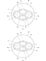
図1および図2は、本発明の一実施形態に係る流路切換弁の弁体の回転軸に沿う断面図(縦断面図)である。図1は、弁体が第1回転位置にある状態を示し、図2は、弁体が第1回転位置から180度回転した第2回転位置にある状態を示す。図1、図2において、流体の流れを矢印で模式的に示している。図3は、図2の流路切換弁の縦断面を斜め方向から見た拡大断面図である。図4は、図1の流路切換弁の分解斜視図である。図5は、図1の流路切換弁の弁本体の斜視図である。図6は、図5の弁本体の弁座面およびその変形例の平面図である。図6(a)は、弁座面の連結部が仮想正円の内側にずれて配置された構成を示し、図6(b)は、弁座面の連結部が仮想楕円に沿って配置された変形例の構成を示す。図7は、図1の流路切換弁の弁体および弁軸の斜視図である。なお、本明細書において、「上下左右」は各図において各部材の相対的な位置関係を示すために用いており、絶対的な位置関係を示すものではない。 1 and 2 are cross-sectional views (vertical cross-sectional views) along the rotation axis of the valve body of the flow path switching valve according to the embodiment of the present invention. FIG. 1 shows a state in which the valve body is in the first rotation position, and FIG. 2 shows a state in which the valve body is in the second rotation position rotated 180 degrees from the first rotation position. In FIGS. 1 and 2, the flow of the fluid is schematically shown by arrows. FIG. 3 is an enlarged cross-sectional view of the vertical cross section of the flow path switching valve of FIG. 2 as viewed from an oblique direction. FIG. 4 is an exploded perspective view of the flow path switching valve of FIG. FIG. 5 is a perspective view of the valve body of the flow path switching valve of FIG. FIG. 6 is a plan view of the valve seat surface of the valve body of FIG. 5 and a modified example thereof. FIG. 6 (a) shows a configuration in which the connecting portion of the valve seat surface is arranged so as to be offset inside the virtual perfect circle, and FIG. 6 (b) shows the connecting portion of the valve seat surface arranged along the virtual ellipse. The configuration of the modified example is shown. FIG. 7 is a perspective view of the valve body and the valve shaft of the flow path switching valve of FIG. In this specification, "up / down / left / right" is used to indicate the relative positional relationship of each member in each figure, and does not indicate an absolute positional relationship.
図1〜図4に示すように、本実施形態の流路切換弁1は、弁本体10と、蓋体20と、弁体30と、駆動部40と、弁軸50と、弾性部材60と、を有している。
As shown in FIGS. 1 to 4, the flow path switching valve 1 of the present embodiment includes a
弁本体10は、合成樹脂を材料として、上部が開口した略有底円筒状に形成されている。弁本体10の周壁部10aには、一方向(図1、図2の左方向)に延びる入口流路11が設けられている。弁本体10の底壁部10bには、下方に向かったのち入口流路11と反対の他方向(図1、図2の右方向)に延びる第1出口流路12が設けられている。また、弁本体10の底壁部10bには、下方に延びる第2出口流路13が設けられている。入口流路11と第1出口流路12と第2出口流路13とは、弁本体10内に設けられた弁室14に通じている。弁室14に通じる流路は、2つまたは4つ以上設けられていてもよい。弁本体10の底壁部10bの内壁面10cには、弁座面15が設けられている。
The
図5に示すように、弁座面15は、底壁部10bの内壁面10cより上方に0.1mm〜5.0mm程度突出した平滑面である。弁座面15には、第1出口流路12に通じる第1ポート16と、第2出口流路13に通じる第2ポート17とが開口して設けられている。出口流路に通じるポートは、出口流路の数に応じて複数設けられる。弁座面15は、第1ポート16および第2ポート17を囲む2つの円形の環状部15a、15aと、環状部15a、15a同士を接続する2つの連結部15b、15bと、を有している。環状部15a、15aと連結部15b、15bとは面一で連なっている。
As shown in FIG. 5, the
本実施形態において、図6(a)に示すように、第1ポート16および第2ポート17の中心O、Oは、仮想正円VC上にその中心(軸線L)を挟んで径方向に対向して配置されている。すなわち、仮想正円VCは、第1ポート16および第2ポート17の中心O、Oを通る。そして、連結部15b、15bが、仮想正円VCの内側にずれて配置されている。これ以外にも、図6(b)に示すように、第1ポート16および第2ポート17の中心O、Oは、仮想楕円VO上にその中心(軸線L)を挟んで径方向(長径、短径でもよい)に対向して配置されており、連結部15b、15bが、仮想楕円VOに沿って配置されていてもよい。仮想楕円VOは、第1ポート16および第2ポート17の中心O、Oを通る。または、連結部15b、15bが、仮想正円VCの外側にずれて配置されていてもよく、仮想正円VCに沿って配置されていてもよい。
In the present embodiment, as shown in FIG. 6A, the centers O and O of the
本実施形態において、弁本体10は金型に樹脂材料を射出する射出成形により得られる。そして、弁座面15が内壁面10cから突出していることから、弁座面15を金型本体に組み込まれるコマにより成形することで、コマのみ高い面精度を必要とし、内壁面10cなどの他の部分を成形する金型本体などについては高い面精度を不要とすることができる。これにより、内壁面10c全体を弁座面とした場合に比べて面積の小さい弁座面15について、安価に面精度を高めることができ、シール性を効果的に確保することができる。
In the present embodiment, the
弁座面15における第1ポート16と第2ポート17との中間箇所には、円柱状の位置決めボス18が立設されている。
A
蓋体20は、合成樹脂を材料として、略円柱状に形成されている。蓋体20は、弁本体10の上部開口を塞ぐように弁本体10に固定して取り付けられ、弁本体10とともに弁室14を画定する。蓋体20の中心には、後述する弁軸50を回転可能に軸支する軸受部21が設けられている。
The
弁体30は、弁室14に収容されて弁座面15上に回転可能に配置される。弁体30は、図1に示す第1回転位置および図2に示す第2回転位置に応じて弁座面15に設けられた第1ポート16および第2ポート17を開閉する。弁体30は、円形部材としての円環部材31および円板部材32と、弁体本体部33と、を有している。
The
円環部材31および円板部材32は、例えば、ポリテトラフルオロエチレン(PTFE)やポリアセタール(POM)などの合成樹脂を切削加工により円環状および円板状に成形した部材である。円環部材31および円板部材32を切削加工により成形することで、射出成形に比べて面精度を高めることができる。円環部材31および円板部材32は、弁座面15に当接されるとともに第1回転位置および第2回転位置において弁座面15の環状部15a,15aと重なる。弁体30を回転軸周りに回転させたときに当該回転軸方向からみると、円環部材31および円板部材32の中心の軌跡は仮想正円VCと一致している。
The
弁体本体部33は、弁部34と、軸部35と、を一体に有している。
The valve body
弁部34は、略長方形板状に形成されている。弁部34の弁座面15側の下面34aには、円環部材31および円板部材32の外径と同一または若干大きい内径を有する円環状のリブ34b、34bが設けられている。弁部34は、リブ34b、34bの内側に円環部材31および円板部材32が配置されることで、弁座面15との間で円環部材31および円板部材32を周方向に回転可能に保持する。また、弁部34における円環部材31の内縁内側に対応する箇所には貫通孔34cが設けられている。なお、円板部材32を円環部材31に置き換えてもよく、また、円環部材31および円板部材32を省略し、第1回転位置および第2回転位置において、円環状のリブ34b、34bが弁座面15の環状部15a,15aと重なるように弁体30を構成してもよい。もちろん、円環部材31および円板部材32を弁体30と一体に形成してもよい。
The
軸部35は、六角形柱状に形成され、弁部34における弁座面15側と反対側の上面34dの中心に直交して立設されている。また、弁体本体部33は、弁部34の下面34aの中心に開口するように、位置決めボス18が回転可能に挿入される位置決め穴38が形成されている。なお、弁体本体部33に位置決めボス18を設け、弁本体10に位置決め穴38を設けてもよい。
The
駆動部40は、図示しないモーターおよび減速機を組み合わせた駆動機構と、この駆動機構を収容する樹脂製の駆動部ケース41と、を有している。駆動部ケース41は、略直方体箱状に形成されている。駆動部ケース41は、蓋体20の上部に固定して取り付けられている。
The
弁軸50は、全体的に円柱状に形成されており、弁座面15に直交するように配置される。弁軸50は、上端から順に、Dカット部51と、セレーション部52と、被支持部53と、弁体取付部54と、を有している。
The
Dカット部51は、円柱の外周面の一部に平坦部が形成されており、弁軸50の周方向の位置決めに用いられる。セレーション部52は、駆動部40の駆動機構の回転駆動力が与えられるギヤ状(セレーション)に形成されている。被支持部53は、軸受部21の内径より若干小さい外径を有する円柱状に形成されている。被支持部53の外周面には、Oリング57、57が装着される溝部53a、53aが設けられている。被支持部53は、軸受部21に挿入され、Oリング57、57によって軸受部21との隙間が封止される。
The D-cut
弁体取付部54は、弁軸50の下端部(一端部)に設けられており、軸受部21の内径より大きい外径を有する円柱状に形成されている。弁体取付部54の下端面には、弁体30の軸部35が挿入される軸部挿入穴55が形成されている。軸部挿入穴55は、軸部35の軸方向(軸線Lに沿う方向)と直交する断面形状(横断面形状)と同一または若干大きめの形状に形成されている。そのため、軸部挿入穴55に挿入された軸部35は、軸方向に移動可能である。また、本実施形態においては、軸部挿入穴55は六角形状に形成されており、弁体30の軸部35と軸部挿入穴55とが嵌まり合い、弁軸50の回転に伴って弁体30が回転される。軸部挿入穴55は、軸部35が挿入され、軸部35が軸方向に移動可能であるとともに、弁軸50の回転に伴って弁体30が回転する形状に形成されていればよい。また、弁軸50の軸部挿入穴55に軸部35が挿入されることで、弁体30および弁軸50内に弾性部材60を収容する収容空間56が形成される。弁体取付部54には、収容空間56とその外部の弁室内の空間とを連通する均圧孔58が設けられている。均圧孔58は、弁体30に設けられていてもよい。
The valve
弾性部材60は、らせん状のコイルバネである。弾性部材60は、収容空間56に軸方向に圧縮された状態で配置されている。弾性部材60は、復元力によって弁体30を弁座面15に押しつける。なお、弾性部材60は、コイルバネ以外にも、ゴム材などで構成されていてもよい。
The
位置決めボス18、軸受部21、弁体30の軸部35および位置決め穴38、弁軸50、ならびに、弾性部材60は、それぞれの軸心が軸線Lと一致するように配置されている。軸線Lは、弁体30の回転軸と一致し、弁座面15と直交する。
The
次に、本実施形態に係る流路切換弁1の動作(作用)について説明する。 Next, the operation (action) of the flow path switching valve 1 according to the present embodiment will be described.
流路切換弁1は、駆動部40の駆動機構の回転駆動力によって弁軸50が軸線Lを中心に回転され、弁軸50の回転に伴って弁体30が弁座面15上で回転されて第1回転位置および第2回転位置に位置づけられる。
In the flow path switching valve 1, the
弁体30は、第1回転位置において、円環部材31が弁座面15の第1ポート16を囲む環状部15aに重なり、円板部材32が弁座面15の第2ポート17を囲む環状部15aに重なる。これにより、弁室14が、弁体30の貫通孔34c、円環部材31および第1ポート16を介して第1出口流路12に通じる。また、円板部材32によって第2ポート17が閉じられて、弁室14と第2出口流路13とが遮断される。
In the
また、弁体30は、第2回転位置において、円環部材31が弁座面15の第2ポート17を囲む環状部15aに重なり、円板部材32が弁座面15の第1ポート16を囲む環状部15aに重なる。これにより、弁室14が、弁体30の貫通孔34c,円環部材31および第2ポート17を介して第2出口流路13に通じる。また、円板部材32によって第1ポート16が閉じられて、弁室14と第1出口流路12とが遮断される。
Further, in the
弁体30は、軸部35が弁軸50の軸部挿入穴55に挿入されることで、弁軸50に軸方向に移動可能に取り付けられている。そして、弁体30および弁軸50内の収容空間56に圧縮された弾性部材60が配置されることにより、弁体30が弁座面15に押しつけられる。これにより、弁体30を安定して弁座面15に密着させることができる。
The
また、例えば、弁体30が第1回転位置にある状態において、第2出口流路13の流体圧力が上昇した場合、弁体30に上向きの力が生じる。この上向きの力が、弾性部材60の復元力より大きくなると、弾性部材60が軸方向に圧縮される。これにより、弁体30が弁座面15から離れるように軸方向に移動して、円板部材32と弁座面15との間に隙間が生じて流体圧力を逃がすことができる。その後、第2出口流路13の流体圧力が低下して、弁体30に生じる上向きの力が弾性部材60の復元力より小さくなると、弾性部材60が伸張する。これにより、弁体30が弁座面15に当接するように軸方向に移動して、円板部材32が弁座面15に密着される。弁体30が第2回転位置にある状態においても同様である。
Further, for example, when the fluid pressure in the second
以上より、本実施形態に係る流路切換弁1によれば、弁体30が、弁座面15に対して直交して配置された弁軸50の弁体取付部54に軸方向に移動可能に取り付けられる。そして、弁体30と弁軸50との間に、軸方向に圧縮された弾性部材60が設けられている。このようにしたことから、弾性部材60の復元力によって弁体30が弁座面15に押しつけられるので、弁体30と弁座面15との間のシール性を安定して確保することができる。また、流体圧力によって弁体30が弁座面15から離れた場合でも、弾性部材の復元力によって確実に元の状態に復帰させることができるので、弁体30と弁座面15との間のシール性を確実に確保することができる。
From the above, according to the flow path switching valve 1 according to the present embodiment, the
また、弾性部材60が、弁体30および弁軸50内の収容空間56に配置されている。このようにすることで、弾性部材60が弁体30および弁軸50に囲われて外部に露出しないので、弾性部材60への流体の影響を低減して、弁体30を弁座面15に安定して押しつけることができる。また、弾性部材60が流体の影響により他の部材と接触することを抑制できる。
Further, the
また、弁軸50には、収容空間56とその外部の弁室14とを連通する均圧孔58が設けられている。このようにすることで、収容空間56とその外部との圧力差をなくして、弁体30が弁軸50に対して安定して移動することができる。
Further, the
また、弁本体10には、弁体30の回転軸と同軸の位置決めボス18が設けられ、弁体30には、位置決めボス18が回転可能に挿入される位置決め穴38が設けられている。このようにすることで、弁体30を容易に精度よく配置することができる。
Further, the
また、弁座面15が、弁本体10の内壁面10cから突出している。このようにすることで、弁座面15における弁体30に当接する面積を少なくすることができ、単位面積あたりの弁体30を弁座面15に押しつける力(圧力)を高めてシール性をより効果的に確保することができる。
Further, the
また、弁座面15が、第1ポート16および第2ポート17を囲む環状部15a,15aと、環状部15a,15a同士を接続する連結部15b、15bと、を有している。連結部15b、15bが、環状部15a、15aの中心O、Oを通る仮想正円VCに対して、内側にずれて配置されている。そして、弁体30が、弁座面15に当接されるとともに第1回転位置および第2回転位置において環状部15a,15aと重なる円環部材31および円板部材32と、円環部材31および円板部材32を周方向に回転可能に保持する弁体本体部33と、を有している。このようにすることで、弁体30の回転(公転)に伴って円環部材31および円板部材32が回転(自転)するので、弁座面15との摺動による弁体30の偏摩耗を低減することができる。なお、図6(b)に示すように、連結部15b、15bが、仮想楕円VOに沿って配置された構成でも同様の効果を奏する。さらに、連結部15b、15bを仮想楕円VOに沿って配置した構成では、円環部材31および円板部材32が自転しない場合(例えば、円環部材および円板部材を弁体と一体にした構成)であっても環状部15a,15aとの摺動部位の集中を防ぎ、摩耗位置を分散できる。
Further, the
上記に本発明の実施形態を説明したが、本発明はこれらの例に限定されるものではない。前述の実施形態に対して、当業者が適宜、構成要素の追加、削除、設計変更を行ったものや、実施形態の特徴を適宜組み合わせたものも、本発明の趣旨に反しない限り、本発明の範囲に含まれる。 Although embodiments of the present invention have been described above, the present invention is not limited to these examples. The present invention also includes those skilled in the art with appropriate additions, deletions, and design changes to the above-described embodiments, and those appropriately combined with the features of the embodiments, unless contrary to the gist of the present invention. Is included in the range of.
1…流路切換弁、10…弁本体、10a…周壁部、10b…底壁部、10c…内壁面、11…入口流路、12…第1出口流路、13…第2出口流路、14…弁室、15…弁座面、15a…環状部、15b…連結部、16…第1ポート、17…第2ポート、18…位置決めボス、20…蓋体、21…軸受部、30…弁体、31…円環部材、32…円板部材、33…弁体本体部、34…弁部、34a…下面、34b…リブ、34c…貫通孔、34d…上面、35…軸部、38…位置決め穴、40…駆動部、41…駆動部ケース、50…弁軸、51…Dカット部、52…セレーション部、53…被支持部、53a…溝部、54…弁体取付部、55…軸部挿入穴、56…収容空間、57…Oリング、58…均圧孔、60…弾性部材、L…軸線、O…ポートの中心、VC…仮想正円、VO…仮想楕円
1 ... Flow path switching valve, 10 ... Valve body, 10a ... Circumferential wall portion, 10b ... Bottom wall portion, 10c ... Inner wall surface, 11 ... Inlet flow path, 12 ... First outlet flow path, 13 ... Second outlet flow path, 14 ... valve chamber, 15 ... valve seat surface, 15a ... annular portion, 15b ... connecting portion, 16 ... first port, 17 ... second port, 18 ... positioning boss, 20 ... lid body, 21 ... bearing portion, 30 ... Valve body, 31 ... annular member, 32 ... disk member, 33 ... valve body main body, 34 ... valve, 34a ... lower surface, 34b ... rib, 34c ... through hole, 34d ... upper surface, 35 ... shaft, 38 ... Positioning hole, 40 ... Drive unit, 41 ... Drive unit case, 50 ... Valve shaft, 51 ... D cut part, 52 ... Serration part, 53 ... Supported part, 53a ... Groove part, 54 ... Valve body mounting part, 55 ... Shaft insertion hole, 56 ... accommodation space, 57 ... O-ring, 58 ... pressure equalizing hole, 60 ... elastic member, L ... axis, O ... port center, VC ... virtual perfect circle, VO ... virtual ellipse
Claims (7)
前記弁軸が、前記弁座面に対して直交して配置され、
前記弁体が、前記弁軸の一端部に軸方向に移動可能に取り付けられ、
前記弁体と前記弁軸との間に、軸方向に圧縮された弾性部材が設けられ、
前記弁座面が、前記弁本体の内壁面から突出していることを特徴とする流路切換弁。 A valve body provided with a valve chamber, a valve body rotatably arranged on the valve seat surface in the valve chamber, and a valve body that opens and closes a port provided on the valve seat surface according to the rotation position, and the valve body. A flow path switching valve having a drive unit having a rotating drive mechanism and a valve shaft connecting the valve body and the drive mechanism.
The valve shaft is arranged orthogonal to the valve seat surface, and the valve shaft is arranged orthogonally to the valve seat surface.
The valve body is attached to one end of the valve shaft so as to be movable in the axial direction.
An elastic member compressed in the axial direction is provided between the valve body and the valve shaft .
A flow path switching valve characterized in that the valve seat surface protrudes from the inner wall surface of the valve body.
前記連結部が、前記複数の環状部の中心を通る仮想正円に対して、内側または外側にずれて配置され、
前記弁体が、前記弁座面に当接される円形部材と、前記円形部材を周方向に回転可能に保持する弁体本体部と、を有していることを特徴とする請求項1に記載の流路切換弁。 The valve seat surface has a plurality of the ports, a plurality of annular portions surrounding each of the plurality of ports, and a connecting portion for connecting the annular portions.
The connecting portion is arranged so as to be offset inward or outward with respect to a virtual perfect circle passing through the centers of the plurality of annular portions.
Said valve body is a circular member which is brought into contact with the valve seat surface, in claim 1, characterized in that it has a, a valve body portion which rotatably supports the circular member in the circumferential direction The flow path switching valve described.
前記連結部が、前記複数の環状部の中心を通る仮想楕円に沿って配置され、
前記弁体が、前記弁座面に当接される円形部材と、前記円形部材を周方向に回転可能に保持する弁体本体部と、を有していることを特徴とする請求項1に記載の流路切換弁。 The valve seat surface has a plurality of the ports, a plurality of annular portions surrounding each of the plurality of ports, and a connecting portion for connecting the annular portions.
The connecting portion is arranged along a virtual ellipse passing through the center of the plurality of annular portions.
Said valve body is a circular member which is brought into contact with the valve seat surface, in claim 1, characterized in that it has a, a valve body portion which rotatably supports the circular member in the circumferential direction The flow path switching valve described.
Priority Applications (3)
| Application Number | Priority Date | Filing Date | Title |
|---|---|---|---|
| JP2018106709A JP6945859B2 (en) | 2018-06-04 | 2018-06-04 | Flow switching valve |
| PCT/JP2019/019477 WO2019235159A1 (en) | 2018-06-04 | 2019-05-16 | Flow passage switching valve |
| CN201980025970.8A CN112189108B (en) | 2018-06-04 | 2019-05-16 | Flow path switching valve |
Applications Claiming Priority (1)
| Application Number | Priority Date | Filing Date | Title |
|---|---|---|---|
| JP2018106709A JP6945859B2 (en) | 2018-06-04 | 2018-06-04 | Flow switching valve |
Publications (3)
| Publication Number | Publication Date |
|---|---|
| JP2019210991A JP2019210991A (en) | 2019-12-12 |
| JP2019210991A5 JP2019210991A5 (en) | 2020-10-01 |
| JP6945859B2 true JP6945859B2 (en) | 2021-10-06 |
Family
ID=68770288
Family Applications (1)
| Application Number | Title | Priority Date | Filing Date |
|---|---|---|---|
| JP2018106709A Active JP6945859B2 (en) | 2018-06-04 | 2018-06-04 | Flow switching valve |
Country Status (3)
| Country | Link |
|---|---|
| JP (1) | JP6945859B2 (en) |
| CN (1) | CN112189108B (en) |
| WO (1) | WO2019235159A1 (en) |
Families Citing this family (1)
| Publication number | Priority date | Publication date | Assignee | Title |
|---|---|---|---|---|
| CN116575542B (en) * | 2023-07-13 | 2023-10-03 | 杭州老板电器股份有限公司 | Distribution assembly and integrated sink |
Family Cites Families (10)
| Publication number | Priority date | Publication date | Assignee | Title |
|---|---|---|---|---|
| DE3808899A1 (en) * | 1988-03-17 | 1989-09-28 | Voss Armaturen | CONTROL VALVE |
| JP2004197899A (en) * | 2002-12-20 | 2004-07-15 | Aisin Seiki Co Ltd | Shut-off valve with built-in diaphragm and fuel cell system |
| JP4119275B2 (en) * | 2003-02-18 | 2008-07-16 | 忠弘 大見 | Diaphragm valve for vacuum exhaust system |
| JP4192141B2 (en) * | 2004-11-26 | 2008-12-03 | 株式会社ケーヒン | Gas shut-off valve |
| US8157184B2 (en) * | 2008-05-29 | 2012-04-17 | Kabushiki Kaisha Saginomiya Seisakusho | Expansion valve, heat pump type refrigeration cycle apparatus, and air handling unit |
| DE102012022213B4 (en) * | 2012-11-07 | 2019-04-25 | Mack & Schneider Gmbh | valve means |
| JP5907506B2 (en) * | 2013-03-22 | 2016-04-26 | 株式会社鷺宮製作所 | Rotary valve device |
| JP6510810B2 (en) * | 2014-12-26 | 2019-05-08 | 株式会社不二工機 | Flow path switching valve |
| CN107606237B (en) * | 2016-07-12 | 2019-07-23 | 杭州三花研究院有限公司 | Volume control device |
| JP6625584B2 (en) * | 2017-05-12 | 2019-12-25 | 株式会社不二工機 | Flow switching valve |
-
2018
- 2018-06-04 JP JP2018106709A patent/JP6945859B2/en active Active
-
2019
- 2019-05-16 CN CN201980025970.8A patent/CN112189108B/en active Active
- 2019-05-16 WO PCT/JP2019/019477 patent/WO2019235159A1/en active Application Filing
Also Published As
| Publication number | Publication date |
|---|---|
| WO2019235159A1 (en) | 2019-12-12 |
| CN112189108B (en) | 2023-01-06 |
| CN112189108A (en) | 2021-01-05 |
| JP2019210991A (en) | 2019-12-12 |
Similar Documents
| Publication | Publication Date | Title |
|---|---|---|
| JP6511427B2 (en) | Flow path switching valve | |
| WO2017057062A1 (en) | Refrigerant control valve device | |
| JP6656846B2 (en) | Flow path switching valve and seal member | |
| JP5681047B2 (en) | Rotating damper | |
| JP6945859B2 (en) | Flow switching valve | |
| US20190136989A1 (en) | Flow path switching valve | |
| JP6661433B2 (en) | Flow path switching valve | |
| JP2022101486A (en) | Rotary valve | |
| JP2020056467A (en) | Flow regulating valve | |
| JP7163695B2 (en) | valve device | |
| US11255449B2 (en) | Valve device | |
| JP7084042B2 (en) | Packing and rotary valves | |
| JP2010261564A (en) | Rotary valve and method for producing the same | |
| JP6689118B2 (en) | Flow path switching valve | |
| JP6639975B2 (en) | Flow path switching valve | |
| JP6955952B2 (en) | Ball valve | |
| JP7093201B2 (en) | Flow path switching valve | |
| JP7036555B2 (en) | Ball valve | |
| JP7287245B2 (en) | control valve | |
| JP7143707B2 (en) | valve device | |
| JP7235328B2 (en) | valve | |
| JP7144956B2 (en) | Ball valve | |
| WO2024058030A1 (en) | Valve device | |
| WO2018043646A1 (en) | Ball valve | |
| JP2022131892A (en) | rotary valve |
Legal Events
| Date | Code | Title | Description |
|---|---|---|---|
| A521 | Request for written amendment filed |
Free format text: JAPANESE INTERMEDIATE CODE: A523 Effective date: 20200818 |
|
| A621 | Written request for application examination |
Free format text: JAPANESE INTERMEDIATE CODE: A621 Effective date: 20200818 |
|
| TRDD | Decision of grant or rejection written | ||
| A01 | Written decision to grant a patent or to grant a registration (utility model) |
Free format text: JAPANESE INTERMEDIATE CODE: A01 Effective date: 20210810 |
|
| A61 | First payment of annual fees (during grant procedure) |
Free format text: JAPANESE INTERMEDIATE CODE: A61 Effective date: 20210908 |
|
| R150 | Certificate of patent or registration of utility model |
Ref document number: 6945859 Country of ref document: JP Free format text: JAPANESE INTERMEDIATE CODE: R150 |