EP2917548B1 - System für die zufuhr einer kryogenen flüssigkeit und verfahren mit aktivem druckaufbau - Google Patents
System für die zufuhr einer kryogenen flüssigkeit und verfahren mit aktivem druckaufbau Download PDFInfo
- Publication number
- EP2917548B1 EP2917548B1 EP13777410.5A EP13777410A EP2917548B1 EP 2917548 B1 EP2917548 B1 EP 2917548B1 EP 13777410 A EP13777410 A EP 13777410A EP 2917548 B1 EP2917548 B1 EP 2917548B1
- Authority
- EP
- European Patent Office
- Prior art keywords
- pressure
- tank
- communication
- sensor
- vapor
- Prior art date
- Legal status (The legal status is an assumption and is not a legal conclusion. Google has not performed a legal analysis and makes no representation as to the accuracy of the status listed.)
- Revoked
Links
Images

Classifications
-
- F—MECHANICAL ENGINEERING; LIGHTING; HEATING; WEAPONS; BLASTING
- F17—STORING OR DISTRIBUTING GASES OR LIQUIDS
- F17C—VESSELS FOR CONTAINING OR STORING COMPRESSED, LIQUEFIED OR SOLIDIFIED GASES; FIXED-CAPACITY GAS-HOLDERS; FILLING VESSELS WITH, OR DISCHARGING FROM VESSELS, COMPRESSED, LIQUEFIED, OR SOLIDIFIED GASES
- F17C7/00—Methods or apparatus for discharging liquefied, solidified, or compressed gases from pressure vessels, not covered by another subclass
- F17C7/02—Discharging liquefied gases
- F17C7/04—Discharging liquefied gases with change of state, e.g. vaporisation
-
- F—MECHANICAL ENGINEERING; LIGHTING; HEATING; WEAPONS; BLASTING
- F02—COMBUSTION ENGINES; HOT-GAS OR COMBUSTION-PRODUCT ENGINE PLANTS
- F02M—SUPPLYING COMBUSTION ENGINES IN GENERAL WITH COMBUSTIBLE MIXTURES OR CONSTITUENTS THEREOF
- F02M21/00—Apparatus for supplying engines with non-liquid fuels, e.g. gaseous fuels stored in liquid form
- F02M21/02—Apparatus for supplying engines with non-liquid fuels, e.g. gaseous fuels stored in liquid form for gaseous fuels
- F02M21/0218—Details on the gaseous fuel supply system, e.g. tanks, valves, pipes, pumps, rails, injectors or mixers
- F02M21/0221—Fuel storage reservoirs, e.g. cryogenic tanks
-
- F—MECHANICAL ENGINEERING; LIGHTING; HEATING; WEAPONS; BLASTING
- F02—COMBUSTION ENGINES; HOT-GAS OR COMBUSTION-PRODUCT ENGINE PLANTS
- F02M—SUPPLYING COMBUSTION ENGINES IN GENERAL WITH COMBUSTIBLE MIXTURES OR CONSTITUENTS THEREOF
- F02M21/00—Apparatus for supplying engines with non-liquid fuels, e.g. gaseous fuels stored in liquid form
- F02M21/02—Apparatus for supplying engines with non-liquid fuels, e.g. gaseous fuels stored in liquid form for gaseous fuels
- F02M21/0218—Details on the gaseous fuel supply system, e.g. tanks, valves, pipes, pumps, rails, injectors or mixers
- F02M21/023—Valves; Pressure or flow regulators in the fuel supply or return system
-
- F—MECHANICAL ENGINEERING; LIGHTING; HEATING; WEAPONS; BLASTING
- F02—COMBUSTION ENGINES; HOT-GAS OR COMBUSTION-PRODUCT ENGINE PLANTS
- F02M—SUPPLYING COMBUSTION ENGINES IN GENERAL WITH COMBUSTIBLE MIXTURES OR CONSTITUENTS THEREOF
- F02M21/00—Apparatus for supplying engines with non-liquid fuels, e.g. gaseous fuels stored in liquid form
- F02M21/02—Apparatus for supplying engines with non-liquid fuels, e.g. gaseous fuels stored in liquid form for gaseous fuels
- F02M21/0218—Details on the gaseous fuel supply system, e.g. tanks, valves, pipes, pumps, rails, injectors or mixers
- F02M21/0287—Details on the gaseous fuel supply system, e.g. tanks, valves, pipes, pumps, rails, injectors or mixers characterised by the transition from liquid to gaseous phase ; Injection in liquid phase; Cooling and low temperature storage
-
- F—MECHANICAL ENGINEERING; LIGHTING; HEATING; WEAPONS; BLASTING
- F17—STORING OR DISTRIBUTING GASES OR LIQUIDS
- F17C—VESSELS FOR CONTAINING OR STORING COMPRESSED, LIQUEFIED OR SOLIDIFIED GASES; FIXED-CAPACITY GAS-HOLDERS; FILLING VESSELS WITH, OR DISCHARGING FROM VESSELS, COMPRESSED, LIQUEFIED, OR SOLIDIFIED GASES
- F17C7/00—Methods or apparatus for discharging liquefied, solidified, or compressed gases from pressure vessels, not covered by another subclass
- F17C7/02—Discharging liquefied gases
-
- B—PERFORMING OPERATIONS; TRANSPORTING
- B60—VEHICLES IN GENERAL
- B60K—ARRANGEMENT OR MOUNTING OF PROPULSION UNITS OR OF TRANSMISSIONS IN VEHICLES; ARRANGEMENT OR MOUNTING OF PLURAL DIVERSE PRIME-MOVERS IN VEHICLES; AUXILIARY DRIVES FOR VEHICLES; INSTRUMENTATION OR DASHBOARDS FOR VEHICLES; ARRANGEMENTS IN CONNECTION WITH COOLING, AIR INTAKE, GAS EXHAUST OR FUEL SUPPLY OF PROPULSION UNITS IN VEHICLES
- B60K15/00—Arrangement in connection with fuel supply of combustion engines or other fuel consuming energy converters, e.g. fuel cells; Mounting or construction of fuel tanks
- B60K15/03—Fuel tanks
- B60K15/03006—Gas tanks
- B60K2015/03013—Control systems for LPG tanks
-
- F—MECHANICAL ENGINEERING; LIGHTING; HEATING; WEAPONS; BLASTING
- F02—COMBUSTION ENGINES; HOT-GAS OR COMBUSTION-PRODUCT ENGINE PLANTS
- F02M—SUPPLYING COMBUSTION ENGINES IN GENERAL WITH COMBUSTIBLE MIXTURES OR CONSTITUENTS THEREOF
- F02M21/00—Apparatus for supplying engines with non-liquid fuels, e.g. gaseous fuels stored in liquid form
- F02M21/02—Apparatus for supplying engines with non-liquid fuels, e.g. gaseous fuels stored in liquid form for gaseous fuels
- F02M21/0203—Apparatus for supplying engines with non-liquid fuels, e.g. gaseous fuels stored in liquid form for gaseous fuels characterised by the type of gaseous fuel
- F02M21/0215—Mixtures of gaseous fuels; Natural gas; Biogas; Mine gas; Landfill gas
-
- F—MECHANICAL ENGINEERING; LIGHTING; HEATING; WEAPONS; BLASTING
- F17—STORING OR DISTRIBUTING GASES OR LIQUIDS
- F17C—VESSELS FOR CONTAINING OR STORING COMPRESSED, LIQUEFIED OR SOLIDIFIED GASES; FIXED-CAPACITY GAS-HOLDERS; FILLING VESSELS WITH, OR DISCHARGING FROM VESSELS, COMPRESSED, LIQUEFIED, OR SOLIDIFIED GASES
- F17C2201/00—Vessel construction, in particular geometry, arrangement or size
- F17C2201/05—Size
- F17C2201/056—Small (<1 m3)
-
- F—MECHANICAL ENGINEERING; LIGHTING; HEATING; WEAPONS; BLASTING
- F17—STORING OR DISTRIBUTING GASES OR LIQUIDS
- F17C—VESSELS FOR CONTAINING OR STORING COMPRESSED, LIQUEFIED OR SOLIDIFIED GASES; FIXED-CAPACITY GAS-HOLDERS; FILLING VESSELS WITH, OR DISCHARGING FROM VESSELS, COMPRESSED, LIQUEFIED, OR SOLIDIFIED GASES
- F17C2201/00—Vessel construction, in particular geometry, arrangement or size
- F17C2201/05—Size
- F17C2201/058—Size portable (<30 l)
-
- F—MECHANICAL ENGINEERING; LIGHTING; HEATING; WEAPONS; BLASTING
- F17—STORING OR DISTRIBUTING GASES OR LIQUIDS
- F17C—VESSELS FOR CONTAINING OR STORING COMPRESSED, LIQUEFIED OR SOLIDIFIED GASES; FIXED-CAPACITY GAS-HOLDERS; FILLING VESSELS WITH, OR DISCHARGING FROM VESSELS, COMPRESSED, LIQUEFIED, OR SOLIDIFIED GASES
- F17C2205/00—Vessel construction, in particular mounting arrangements, attachments or identifications means
- F17C2205/01—Mounting arrangements
- F17C2205/0123—Mounting arrangements characterised by number of vessels
- F17C2205/013—Two or more vessels
- F17C2205/0134—Two or more vessels characterised by the presence of fluid connection between vessels
-
- F—MECHANICAL ENGINEERING; LIGHTING; HEATING; WEAPONS; BLASTING
- F17—STORING OR DISTRIBUTING GASES OR LIQUIDS
- F17C—VESSELS FOR CONTAINING OR STORING COMPRESSED, LIQUEFIED OR SOLIDIFIED GASES; FIXED-CAPACITY GAS-HOLDERS; FILLING VESSELS WITH, OR DISCHARGING FROM VESSELS, COMPRESSED, LIQUEFIED, OR SOLIDIFIED GASES
- F17C2221/00—Handled fluid, in particular type of fluid
- F17C2221/03—Mixtures
- F17C2221/032—Hydrocarbons
- F17C2221/033—Methane, e.g. natural gas, CNG, LNG, GNL, GNC, PLNG
-
- F—MECHANICAL ENGINEERING; LIGHTING; HEATING; WEAPONS; BLASTING
- F17—STORING OR DISTRIBUTING GASES OR LIQUIDS
- F17C—VESSELS FOR CONTAINING OR STORING COMPRESSED, LIQUEFIED OR SOLIDIFIED GASES; FIXED-CAPACITY GAS-HOLDERS; FILLING VESSELS WITH, OR DISCHARGING FROM VESSELS, COMPRESSED, LIQUEFIED, OR SOLIDIFIED GASES
- F17C2223/00—Handled fluid before transfer, i.e. state of fluid when stored in the vessel or before transfer from the vessel
- F17C2223/01—Handled fluid before transfer, i.e. state of fluid when stored in the vessel or before transfer from the vessel characterised by the phase
- F17C2223/0146—Two-phase
- F17C2223/0153—Liquefied gas, e.g. LPG, GPL
- F17C2223/0161—Liquefied gas, e.g. LPG, GPL cryogenic, e.g. LNG, GNL, PLNG
-
- F—MECHANICAL ENGINEERING; LIGHTING; HEATING; WEAPONS; BLASTING
- F17—STORING OR DISTRIBUTING GASES OR LIQUIDS
- F17C—VESSELS FOR CONTAINING OR STORING COMPRESSED, LIQUEFIED OR SOLIDIFIED GASES; FIXED-CAPACITY GAS-HOLDERS; FILLING VESSELS WITH, OR DISCHARGING FROM VESSELS, COMPRESSED, LIQUEFIED, OR SOLIDIFIED GASES
- F17C2227/00—Transfer of fluids, i.e. method or means for transferring the fluid; Heat exchange with the fluid
- F17C2227/01—Propulsion of the fluid
- F17C2227/0107—Propulsion of the fluid by pressurising the ullage
-
- F—MECHANICAL ENGINEERING; LIGHTING; HEATING; WEAPONS; BLASTING
- F17—STORING OR DISTRIBUTING GASES OR LIQUIDS
- F17C—VESSELS FOR CONTAINING OR STORING COMPRESSED, LIQUEFIED OR SOLIDIFIED GASES; FIXED-CAPACITY GAS-HOLDERS; FILLING VESSELS WITH, OR DISCHARGING FROM VESSELS, COMPRESSED, LIQUEFIED, OR SOLIDIFIED GASES
- F17C2227/00—Transfer of fluids, i.e. method or means for transferring the fluid; Heat exchange with the fluid
- F17C2227/03—Heat exchange with the fluid
- F17C2227/0302—Heat exchange with the fluid by heating
-
- F—MECHANICAL ENGINEERING; LIGHTING; HEATING; WEAPONS; BLASTING
- F17—STORING OR DISTRIBUTING GASES OR LIQUIDS
- F17C—VESSELS FOR CONTAINING OR STORING COMPRESSED, LIQUEFIED OR SOLIDIFIED GASES; FIXED-CAPACITY GAS-HOLDERS; FILLING VESSELS WITH, OR DISCHARGING FROM VESSELS, COMPRESSED, LIQUEFIED, OR SOLIDIFIED GASES
- F17C2227/00—Transfer of fluids, i.e. method or means for transferring the fluid; Heat exchange with the fluid
- F17C2227/03—Heat exchange with the fluid
- F17C2227/0367—Localisation of heat exchange
- F17C2227/0388—Localisation of heat exchange separate
- F17C2227/0393—Localisation of heat exchange separate using a vaporiser
-
- F—MECHANICAL ENGINEERING; LIGHTING; HEATING; WEAPONS; BLASTING
- F17—STORING OR DISTRIBUTING GASES OR LIQUIDS
- F17C—VESSELS FOR CONTAINING OR STORING COMPRESSED, LIQUEFIED OR SOLIDIFIED GASES; FIXED-CAPACITY GAS-HOLDERS; FILLING VESSELS WITH, OR DISCHARGING FROM VESSELS, COMPRESSED, LIQUEFIED, OR SOLIDIFIED GASES
- F17C2265/00—Effects achieved by gas storage or gas handling
- F17C2265/06—Fluid distribution
- F17C2265/066—Fluid distribution for feeding engines for propulsion
-
- F—MECHANICAL ENGINEERING; LIGHTING; HEATING; WEAPONS; BLASTING
- F17—STORING OR DISTRIBUTING GASES OR LIQUIDS
- F17C—VESSELS FOR CONTAINING OR STORING COMPRESSED, LIQUEFIED OR SOLIDIFIED GASES; FIXED-CAPACITY GAS-HOLDERS; FILLING VESSELS WITH, OR DISCHARGING FROM VESSELS, COMPRESSED, LIQUEFIED, OR SOLIDIFIED GASES
- F17C2270/00—Applications
- F17C2270/01—Applications for fluid transport or storage
- F17C2270/0102—Applications for fluid transport or storage on or in the water
- F17C2270/0105—Ships
- F17C2270/0107—Wall panels
-
- F—MECHANICAL ENGINEERING; LIGHTING; HEATING; WEAPONS; BLASTING
- F17—STORING OR DISTRIBUTING GASES OR LIQUIDS
- F17C—VESSELS FOR CONTAINING OR STORING COMPRESSED, LIQUEFIED OR SOLIDIFIED GASES; FIXED-CAPACITY GAS-HOLDERS; FILLING VESSELS WITH, OR DISCHARGING FROM VESSELS, COMPRESSED, LIQUEFIED, OR SOLIDIFIED GASES
- F17C2270/00—Applications
- F17C2270/01—Applications for fluid transport or storage
- F17C2270/0165—Applications for fluid transport or storage on the road
- F17C2270/0168—Applications for fluid transport or storage on the road by vehicles
- F17C2270/0178—Cars
-
- Y—GENERAL TAGGING OF NEW TECHNOLOGICAL DEVELOPMENTS; GENERAL TAGGING OF CROSS-SECTIONAL TECHNOLOGIES SPANNING OVER SEVERAL SECTIONS OF THE IPC; TECHNICAL SUBJECTS COVERED BY FORMER USPC CROSS-REFERENCE ART COLLECTIONS [XRACs] AND DIGESTS
- Y02—TECHNOLOGIES OR APPLICATIONS FOR MITIGATION OR ADAPTATION AGAINST CLIMATE CHANGE
- Y02T—CLIMATE CHANGE MITIGATION TECHNOLOGIES RELATED TO TRANSPORTATION
- Y02T10/00—Road transport of goods or passengers
- Y02T10/10—Internal combustion engine [ICE] based vehicles
- Y02T10/30—Use of alternative fuels, e.g. biofuels
Definitions
- the present invention relates generally to cryogenic delivery systems and methods and, in particular, to a cryogenic liquid delivery system and method with active pressure building capabilities.
- This invention relates to a delivery system and method of a cryogenic fluid, such as liquefied natural gas (LNG), from a storage tank to a use device, such as a natural gas powered vehicle engine.
- a cryogenic fluid such as liquefied natural gas (LNG)
- LNG liquefied natural gas
- An embodiment of the system of the invention is particularly suited for markets in which pre-saturation of the LNG fuel is not performed, though it may also function as a source of "trim heat" if the tank pressure falls below a pre-defined level.
- One proposed method for building tank pressure is to utilize a pressure building circuit that is common on many stationary cryogenic cylinders. These circuits function by utilizing gravity to feed liquid cryogen into a vaporizer. Upon vaporization of the liquid, its volume expands and the evolved gas is routed to the vapor space above the cryogen, building a head of vapor pressure above the liquid phase in the tank.
- this type of circuit for LNG vehicle tanks there are three distinct problems with this type of circuit for LNG vehicle tanks. First, as most LNG vehicle tanks are mounted horizontally, there is small liquid head pressure compared to a vertical tank to force liquid into the vaporizer. Second, since LNG vehicle tanks are used in mobile applications, any vapor pressure that is built above the liquid phase will quickly collapse as soon as the vehicle is in motion and the liquid and vapor phases mix.
- LNG liquid natural gas
- the LNG delivery system described below overcomes the aforementioned shortcomings of the prior art by including a compressor or pump situated on a parallel path downstream of the vaporizer to actively force natural gas vapor back into the vehicle fuel tank, adding heat to the tank at a rate that far exceeds that which could be accomplished by passive systems. Compressor operation is controlled by a control system that monitors the system pressure, turning the compressor on when system pressure is low and off when the system pressure reaches a predefined point. Once the liquid is saturated, the LNG delivery system functions as the system described in commonly owned U.S. Patent No. 5,421,161 to Gustafson .
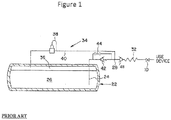
- FIG. 1 depicts the fuel delivery system in the '161 patent and a brief description is included here for clarity.
- a cryogenic tank 22 contains cryogenic product such as LNG consisting of liquid cryogen 26 with a vapor filling the tank vapor space or head space 36 above it.
- Liquid line 24 communicates with the bottom of tank 22 where liquid 26 is contained.
- Product withdrawal line 28 connects liquid line 24 to the gas use device such as a vehicle engine.
- a heat exchanger or vaporizer 32 is located in withdrawal line 28 to vaporize the cryogen before it is delivered to the use device.
- the withdrawal line also contains a tank mounted excess flow valve 48, which protects the downstream piping in case of a line break.
- Valve 10 in withdrawal line 28 may be taken to represent the throttle of a vehicle with the idea that demand for product is constantly changing.
- Economizer circuit 34 includes vapor tube 40, which communicates with head space 36, and includes economizer regulator 38, which is set at a predetermined pressure threshold. In this manner, when the pressure in tank 22 exceeds the set point of regulator 38, the vapor in head space 36 may be withdrawn through vapor line 40 and to the use device through withdrawal line 28, which lowers the pressure in tank 22.
- a biasing relief valve 42 is included in liquid line 24 to cause economizer circuit 34 to be the path of least resistance when regulator 38 is open.
- a small orifice 44 is located in parallel with relief valve 42 to allow back flow to the tank during transient periods of high to low use.
- Inlet line 51 branches off withdrawal line 28 downstream of vaporizer 32.
- Flow inducer 52 causes vaporized gas to flow from inlet line 51 to outlet line 53 which returns the gas to vapor line 40 through check valve 54.
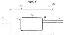
- FIG. 3 shows one possible embodiment of the flow inducing device 52.
- Pressure vessel 60 operates at the same pressure as outlet line 53.
- Compressor 61 has inlet 63 piped directly to inlet line 51 and has outlet 65 open to the interior of vessel 60.
- flow inducing device 52 is not limited to a compressor housed inside a pressure vessel, but may take on other forms of actively moving a fluid against a pressure gradient such as a positive displacement pump or other type of motor. Additionally, the process piping of the flow inducing device may be configured in other manners, such as by piping the compressor outlet to the tank and leaving the compressor inlet open to the interior of the vessel.
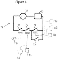
- FIG. 4 shows one possible embodiment of a controller or control system circuit to activate or deactivate the flow inducing device.
- a power source such as a battery 75, supplies a voltage to device 60 via electrical circuit 76.
- the voltage is controlled by several relays and switches (where the terms “relay” and “switch” are used interchangeably herein), which dictate logical events that must occur simultaneously to in order to supply power to device 60.
- the vehicle's ignition switch or key In order for flow inducing device 60 to operate, the vehicle's ignition switch or key must be turned on to close ignition relay 70, and the system pressure must be below a predetermined threshold to close pressure relay 71.
- the engine is operating in order for device 60 to operate for two reasons: first, to avoid excessive vehicle battery drain and second, to ensure an adequate amount of heat is supplied to vaporizer 32.
- a signal indicating that the engine is in operation will close engine operating relay 72.
- a manual bypass switch 73, connected in parallel with engine operating relay 72, is provided for rare instances when a user may desire to operate the compressor when the engine is not operating (for example, when the tank pressure is too low to even support the engine to start).
- the signal to close ignition relay 70 can be simply taken from the vehicle's ignition switch 80 ( Figure 4 ).
- the signal to close pressure relay 71 requires that the pressure in the system is below a predefined limit. Therefore, a pressure switch or sensor should be included in the system of Figure 2 to sense a system pressure in one of several locations such as the head space 36 of the tank, as illustrated by sensor 82 in Figures 2 and 4 , or somewhere in pressure building circuit 55, as illustrated by sensor 83 in Figures 2 and 4 , and can be used to close relay 71 when the sensed pressure is below the pressure threshold or predetermined minimum pressure.
- a signal to close the engine operating relay 72 may come from a variety of sources that may serve as an engine operating sensor.
- the most direct source would be a signal from the on-vehicle electrical system, 84 in Figure 4 , that senses if the engine is operating or not via the engine's electronic control circuitry.
- an indirect method of detecting the engine operating may be used by including a temperature switch or sensor in inlet line 51, as illustrated by sensor 86 in Figures 2 and 4 , or in the heat exchange space surrounding vaporizer 32, as illustrated by sensor 88 in Figures 2 and 4 , such that relay 72 closes if the temperature is above a predetermined threshold.
- the controller may take on other forms not limited to the above description.
- the primary goals of the control system are 1) to prevent over-pressurization of the cryogenic tank; 2) to prevent excessive discharge of the vehicle's battery when the engine is not operating; and 3) to avoid damage to both vaporizer 32 and flow inducing device 52 due to low temperatures when the engine is not operating.
- the controller could be omitted completely and the control system could consist of simply a manually controlled "on” and "off switch or other manual control switch or device.
- a typical setup and operation of the described system in accordance with an embodiment of the method of the invention is as follows.
- the minimum allowable inlet pressure to the engine is 70 psig.
- the economizer regulator is set to open at 100 psig, which will work to lower tank pressure to this level when tank pressure exceeds that value. With an economizer set at 100 psig, it would be logical to have the set point on the flow inducing device around 95 psig.
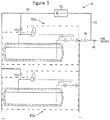
- a single pressure building circuit 55 may be used in a system consisting of multiple tanks 80a, 80b, etc. (while two tanks are shown, an alternative number may be used) configured in parallel.
- inlet line 51 branches off of the withdrawal line downstream of vaporizer 32, and a flow inducer 52 causes vaporized gas to flow from inlet line 51 to outlet line 53.
- Outlet line 53 returns the gas to the vapor line of the economizer circuit and then to the tank head space via check valves 54a and 54b for tanks 80a and 80b, respectively.
- the controller or control system circuit illustrated in Figure 4 may also be used to activate or deactivate the flow inducing device 52 of Figure 5 .
- alternative controllers or control system circuits could be used.
- the signal to close pressure relay 71 requires that the pressure in the system is below a predefined limit. Therefore, a pressure switch or sensor should be included in the system of Figure 5 to sense a system pressure in several locations, such as the head spaces of the tanks 80a and 80b or somewhere in pressure building circuit 55, and can be used to close relay 71 of Figure 4 when the sensed pressure is below the pressure threshold or predetermined minimum pressure.
- the check valve corresponding to the tank that is not below the pressure threshold or minimum pressure (check valve 54b in the present example) will prevent gas from the pressure building circuit 55 from entering that tank (tank 80b in the present example).
Landscapes
- Engineering & Computer Science (AREA)
- Chemical & Material Sciences (AREA)
- Mechanical Engineering (AREA)
- General Engineering & Computer Science (AREA)
- Chemical Kinetics & Catalysis (AREA)
- General Chemical & Material Sciences (AREA)
- Oil, Petroleum & Natural Gas (AREA)
- Combustion & Propulsion (AREA)
- Filling Or Discharging Of Gas Storage Vessels (AREA)
Claims (16)
- Abgabesystem für kryogenes Fluid, Folgendes umfassend:a) einen Tank (22) zum Aufnehmen einer Zufuhr von kryogener Flüssigkeit (26), wobei der Tank einen Kopfraum (36) zum Aufnehmen eines Dampfes über der in dem Tank aufbewahrten kryogenen Flüssigkeit einschließt;b) eine Flüssigkeitsentnahmeleitung (28) zum Verbinden mit in dem Tank aufbewahrter kryogener Flüssigkeit;c) eine Dampfabgabeleitung (40);d) einen Verdampfer (32) mit einem Einlass in Verbindung mit der Flüssigkeitsentnahmeleitung und einem Auslass in Verbindung mit der Dampfabgabeleitung;dadurch gekennzeichnet, dass das Abgabesystem für kryogenes Fluid ferner umfasst:e) einen Druckaufbaukreis (55) in Verbindung mit der Dampfzufuhrleitung und dem Kopfraum des Tanks, wobei der Druckaufbaukreis eine Strömungserzeugungsvorrichtung (52) und eine Dampfleitung (53, 40) einschließt, die in einem oberen Abschnitt des Tanks endet und in Verbindung mit dem Kopfraum an der Oberseite des Tanks steht, wobei die Strömungserzeugungsvorrichtung verursacht, dass verdampftes Gas zur Dampfleitung und in den Kopfraum strömt; undf) eine Steuerung in Verbindung mit der Strömungserzeugungsvorrichtung.
- Abgabesystem für kryogenes Fluid nach Anspruch 1, wobei das System ferner einen Vorwärmerkreis (34) in Verbindung mit der Flüssigkeitsentnahmeleitung und dem Kopfraum des Tanks umfasst, wobei der Vorwärmerkreis ausgelegt ist, um Dampf vom Kopfraum zu der Flüssigkeitsentnahmeleitung zu leiten, wenn ein Druck in dem Tank über einen vorbestimmten maximalen Druck ansteigt.
- Abgabesystem für kryogenes Fluid nach Anspruch 1, wobei der Druckaufbaukreis eine Einlassleitung (51) in Verbindung mit der Dampfabgabeleitung und einem Einlass der Strömungserzeugungsvorrichtung einschließt; und eine Auslassleitung (53), die mit einem Auslass der Strömungserzeugungsvorrichtung und dem Kopfraum des Tanks in Verbindung steht.
- Abgabesystem für kryogenes Fluid nach Anspruch 3, wobei die Auslassleitung ein Rückschlagventil (54) umfasst, das ermöglicht, dass Dampf durch die Auslassleitung zu dem Kopfraum strömt.
- Abgabesystem für kryogenes Fluid nach Anspruch 3, wobei die Strömungserzeugungsvorrichtung einen Kompressor (61) umfasst, wobei wahlweise:die Stromerzeugungsvorrichtung einen Druckbehälter (60) mit dem darin angeordneten Kompressor einschließtunddie Einlassleitung (51) in Verbindung mit einem Einlass (63) des Kompressors oder des Druckbehälters steht unddie Auslassleitung (53) in Verbindung mit einem Auslass (65) des Druckbehälters oder des Kompressors steht.
- Abgabesystem für kryogenes Fluid nach Anspruch 1, ferner umfassend:g) einen zweiten Tank (80b) zum Aufnehmen einer Zufuhr von kryogener Flüssigkeit, wobei der zweite Tank einen Kopfraum zum Aufnehmen eines Dampfes über in dem zweiten Tank aufbewahrter kryogener Flüssigkeit einschließt;h) eine zweite Flüssigkeitsentnahmeleitung, die ausgelegt ist, um mit in dem zweiten Tank aufbewahrter kryogener Flüssigkeit in Verbindung zu stehen;i) wobei die zweite Flüssigkeitsentnahmeleitung auch in Verbindung mit dem Einlass des Verdampfers steht und der Druckaufbaukreis auch in Verbindung mit dem Kopfraum des zweiten Tanks steht.
- Abgabesystem für kryogenes Fluid nach Anspruch 1, ferner eine Stromquelle (75) und einen Drucksensor (82, 83) umfassend, der ausgelegt ist, um einen Druck des Systems zu erfassen, und wobei das Steuersystem eine Steuerung mit einer Schaltung in Verbindung mit der Stromquelle und der Strömungserzeugungsvorrichtung (60) einschließt, wobei die Schaltung ein Druckrelais (71) in Verbindung mit dem Drucksensor einschließt, wobei das Druckrelais sich schließt, wenn der durch den Drucksensor erfasste Druck unter einen vorbestimmten Mindestdruck fällt, so dass die Strömungserzeugungsvorrichtung aktiviert wird.
- Abgabesystem für kryogenes Fluid nach Anspruch 7, wobei
der Drucksensor (82) einen Druck in dem Kopfraum des Tanks erfasst oder
der Drucksensor (83) einen Druck im Druckaufbaukreis erfasst. - Abgabesystem für kryogenes Fluid nach Anspruch 1, ferner umfassend
eine Stromquelle (75), einen Drucksensor (82, 83) zum Erfassen eines Drucks des Systems und einen Zündungssensor zum Erfassen, wenn ein Zündschalter (80) eingeschaltet ist, und wobei das Steuersystem eine Steuerung mit einer Schaltung in Verbindung mit der Stromquelle und der Strömungserzeugungsvorrichtung (60) einschließt, wobei die Schaltung ein Druckrelais (71) in Verbindung mit dem Drucksensor und ein Zündrelais (70) in Verbindung mit dem Zündungssensor einschließt, wobei das Druckrelais schließt, wenn der vom Drucksensor erfasste Druck unter einen vorbestimmten Mindestdruck fällt, und das Zündrelais schließt, wenn der Zündungssensor erkennt, dass der Zündschalter eingeschaltet ist, so dass die Strömungserzeugungsvorrichtung Strom von der Stromquelle erhält, wenn die Druck- und die Zündrelais geschlossen sind. - Abgabesystem für kryogenes Fluid nach Anspruch 1, ferner umfassend eine Stromquelle (75), einen Drucksensor (82, 83) zum Erfassen eines Drucks des Systems und einen Motorbetriebssensor (84) zum Erfassen, wenn ein von dem kryogenen Fluid angetriebener Motor in Betrieb ist, und wobei das Steuersystem eine Steuerung mit einer Schaltung in Verbindung mit der Stromquelle und der Strömungserzeugungsvorrichtung (60) einschließt, wobei die Schaltung ein Druckrelais (71) in Verbindung mit dem Drucksensor und ein Motorbetriebsrelais (72) in Verbindung mit dem Motorbetriebssensor einschließt, wobei das Druckrelais schließt, wenn der vom Drucksensor erfasste Druck unter einen vorbestimmten Mindestdruck fällt, und das Motorbetriebsrelais schließt, wenn der Motorbetriebssensor erkennt, dass der Motor in Betrieb ist, so dass die Strömungserzeugungsvorrichtung Strom von der Stromquelle erhält, wenn die Druck- und Motorbetriebsrelais geschlossen sind.
- Abgabesystem für kryogenes Fluid nach Anspruch 10, wobei der Motorbetriebssensor einschließta) ein elektrisches System am Fahrzeug (84) oderb) einen Temperatursensor (86, 88) in Verbindung mit dem Druckaufbaukreis.
- Abgabesystem für kryogenes Fluid nach Anspruch 10, wobei der Motorbetriebssensor (84) einen Temperatursensor (88) in Verbindung mit einem Wärmeaustauschraum um den Verdampfer steht.
- Abgabesystem für kryogenes Fluid nach Anspruch 1, ferner umfassend eine Stromquelle (75), einen Drucksensor (82, 83) zum Erfassen eines Drucks des Systems, einen Zündungssensor zum Erfassen, wenn ein Zündschalter (70) eingeschaltet ist, und einen Motorbetriebssensor (84) zum Erfassen, wenn ein durch das kryogene Fluid betriebener Motor in Betrieb ist, und wobei das Steuersystem eine Steuerung mit einer Schaltung in Verbindung mit der Stromquelle und der Strömungserzeugungsvorrichtung (60) aufweist, wobei die Schaltung ein Druckrelais (71) in Verbindung mit dem Drucksensor, ein Zündrelais (70) in Verbindung mit dem Zündungssensor und ein Motorbetriebsrelais (72) in Verbindung mit dem Motorbetriebssensor einschließt, wobei das Druckrelais schließt, wenn der durch den Drucksensor erfasste Druck einen vorbestimmten Mindestdruck unterschreitet, wobei das Zündrelais schließt, wenn der Zündungssensor erfasst, dass der Zündschalter eingeschaltet ist, und das Motorbetriebsrelais schließt, wenn der Motorbetriebssensor erfasst, dass der Motor in Betrieb ist, so dass die Strömungserzeugungsvorrichtung Strom von der Stromquelle erhält, wenn die Druck-, Zünd- und Motorbetriebsrelais geschlossen sind.
- Abgabesystem für kryogenes Fluid nach Anspruch 12 oder 13, ferner umfassend einen Umgehungsschalter (73), der parallel zu dem Motorbetriebsrelais angeschlossen ist.
- Verfahren zur Abgabe eines kryogenen Fluids, umfassend die folgenden Schritte:a) Speichern von unter Druck stehender kryogener Flüssigkeit in einem Tank (22) mit einem Kopfraum (36);b) Entnehmen von kryogener Flüssigkeit aus dem Tank unter Verwendung einer Flüssigkeitsentnahmeleitung (28);c) Verdampfen der aus dem Tank entnommenen kryogener Flüssigkeit, um einen Dampf zu erzeugen;d) Zuführen des Dampfes zu einer Verwendungsvorrichtung unter Verwendung einer Dampfabgabeleitung (40); gekennzeichnet durch den Schritte) der Druckbeaufschlagung des Tanks durch Abziehen von Dampf aus der Dampfabgabeleitung und Erzeugen von Strömung des Dampfes zum Kopfraum an der Oberseite des Tanks über eine Dampfleitung, die in einem oberen Abschnitt des Tanks endet, unter Verwendung einer Strömungserzeugungsvorrichtung (52).
- Verfahren zur Abgabe eines kryogenen Fluids nach Anspruch 15, ferner umfassendA) den Schritt des Entnehmens von Dampf aus dem Kopfraum (36) des Tanks (22) und Leiten desselben zu der Flüssigkeitsentnahmeleitung (28), wenn der Tank einen vorbestimmten Druck überschreitet; oderB) den Schritt des Erfassens eines Systemdrucks und des Ausführens von Schritt e), wenn der Systemdruck unter einen vorbestimmten Mindestdruck fällt; oderC) die Schritte des Erfassens eines Systemdrucks und des Erfassens, ob ein Zündschalter (70) eingeschaltet ist, und des Durchführens von Schritt e), wenn der Systemdruck unter einen vorbestimmten Mindestdruck fällt und der Zündschalter eingeschaltet ist; oderD) die Schritte des Erfassens eines Systemdrucks und des Erfassens, ob ein durch das kryogene Fluid angetriebener Motor in Betrieb ist, und des Ausführens von Schritt e), wenn der Systemdruck unter einen vorbestimmten Mindestdruck fällt und der Motor in Betrieb ist; oderE) die Schritte des Erfassens eines Systemdrucks, des Erfassens, ob ein Zündschalter eingeschaltet ist, und des Erfassens, ob ein durch das kryogene Fluid angetriebener Motor in Betrieb ist, und des Ausführens von Schritt e), wenn der Systemdruck unter einen vorbestimmten Mindestdruck fällt, der Zündschalter eingeschaltet ist und der Motor in Betrieb ist; oderF) die Schritte des:f) Speicherns von unter Druck stehender kryogener Flüssigkeit in einem zweiten Tank (80b) mit einem Kopfraum;g) Entnehmens von unter Druck stehender kryogener Flüssigkeit aus dem zweiten Tank unter Verwendung einer zweiten Flüssigkeitsentnahmeleitung; und wobei Schritt c) auch Verdampfen der aus dem zweiten Tank entnommenen kryogenen Flüssigkeit umfasst und Schritt e) auch das mit Druck Beaufschlagen des zweiten Tanks einschließt, indem Strömung von kryogenem Dampf, der aus der Dampfabgabeleitung zu dem Kopfraum des zweiten Tanks entnommen wird, unter Verwendung der Strömungserzeugungsvorrichtung erzeugt wird.
Applications Claiming Priority (2)
| Application Number | Priority Date | Filing Date | Title |
|---|---|---|---|
| US201261708749P | 2012-10-02 | 2012-10-02 | |
| PCT/US2013/063116 WO2014055681A1 (en) | 2012-10-02 | 2013-10-02 | Cryogenic liquid delivery system and method with active pressure building capabilities |
Publications (2)
| Publication Number | Publication Date |
|---|---|
| EP2917548A1 EP2917548A1 (de) | 2015-09-16 |
| EP2917548B1 true EP2917548B1 (de) | 2019-07-24 |
Family
ID=49382618
Family Applications (1)
| Application Number | Title | Priority Date | Filing Date |
|---|---|---|---|
| EP13777410.5A Revoked EP2917548B1 (de) | 2012-10-02 | 2013-10-02 | System für die zufuhr einer kryogenen flüssigkeit und verfahren mit aktivem druckaufbau |
Country Status (7)
| Country | Link |
|---|---|
| US (1) | US9903534B2 (de) |
| EP (1) | EP2917548B1 (de) |
| CN (2) | CN203384645U (de) |
| AU (1) | AU2013327149B2 (de) |
| CA (1) | CA2887041C (de) |
| ES (1) | ES2751399T3 (de) |
| WO (1) | WO2014055681A1 (de) |
Families Citing this family (22)
| Publication number | Priority date | Publication date | Assignee | Title |
|---|---|---|---|---|
| CN203384645U (zh) * | 2012-10-02 | 2014-01-08 | 查特股份有限公司 | 具有主动式增压能力的深冷液体输送及增压系统 |
| US9541032B2 (en) * | 2014-05-16 | 2017-01-10 | Adsorbed Natural Gas Products, Inc. | Sorbent-based low pressure gaseous fuel delivery system |
| EP3149390B1 (de) * | 2014-05-29 | 2023-07-05 | Chart Inc. | System zur bereitstellung von flüssigerdgas mit gesättigter kraftstoffreserve |
| CN104100416A (zh) * | 2014-07-01 | 2014-10-15 | 张家港保税区长江新能源装备有限公司 | 一种气瓶的自增压系统 |
| CN104456075A (zh) * | 2014-12-02 | 2015-03-25 | 上海雷尼威尔技术有限公司 | 车用lng气瓶控制系统 |
| CA2970356A1 (en) * | 2014-12-12 | 2016-06-16 | Chart Inc. | System and method for manifolding portable cryogenic containers |
| CN104948909B (zh) * | 2015-05-20 | 2017-05-17 | 岳阳长岭炼化通达建筑安装工程有限公司 | 液化气体自增压汽化输送系统及方法 |
| WO2017000072A1 (en) | 2015-06-29 | 2017-01-05 | Westport Power Inc. | Multi-vessel fluid storage and delivery system |
| WO2017054888A1 (en) * | 2015-10-02 | 2017-04-06 | Volvo Truck Corporation | A gas tank arrangement for a dual fuel internal combustion engine |
| CN105221930B (zh) * | 2015-11-05 | 2017-09-08 | 江南工业集团有限公司 | 车用液化天然气气瓶自增压装置 |
| US10590866B2 (en) * | 2015-11-13 | 2020-03-17 | Volvo Truck Corporation | Method and an apparatus for controlling an internal combustion engine with a high pressure gas injection |
| DE102016208166A1 (de) * | 2016-05-12 | 2017-11-16 | Robert Bosch Gmbh | Kraftstoffversorgungssystem für eine gasbetriebene Brennkraftmaschine und Verfahren zum Betreiben eines Kraftstoffversorgungssystems |
| KR101745270B1 (ko) * | 2016-07-13 | 2017-06-08 | 현대자동차주식회사 | 바이퓨얼 차량의 lpg 봄베 냉각 시스템 |
| EP3348894B1 (de) * | 2017-01-17 | 2019-10-30 | Chart Inc. | Kryobehälter mit reservedruckaufbaukammer |
| JP7125424B2 (ja) | 2017-04-25 | 2022-08-24 | チャート・インコーポレーテッド | 圧力上昇極低温流体供給システム |
| US10113696B1 (en) | 2017-06-30 | 2018-10-30 | Adsorbed Natural Gas Products, Inc. | Integrated on-board low-pressure adsorbed natural gas storage system for an adsorbed natural gas vehicle |
| WO2020018569A1 (en) * | 2018-07-16 | 2020-01-23 | Lawrence Livermore National Security, Llc | System and method to cost-effectively pressurize cryogenic h2 by heat transfer |
| IT201800010216A1 (it) * | 2018-11-09 | 2020-05-09 | Iveco Magirus | Sistema di controllo di spillamento per un serbatoio di carburante |
| JP7028156B2 (ja) * | 2018-12-27 | 2022-03-02 | トヨタ自動車株式会社 | 液体水素タンクにおける液面測定方法及び液体水素貯蔵システム |
| EP3722652B1 (de) * | 2019-04-09 | 2022-09-14 | MAGNA STEYR Fahrzeugtechnik AG & Co KG | Speicherbehälter für tiefkaltes flüssiggas |
| CN111895267B (zh) * | 2020-07-27 | 2022-03-01 | 一汽解放汽车有限公司 | 一种车载气瓶增压控制系统及其控制方法 |
| SE545674C2 (en) * | 2021-06-15 | 2023-11-28 | Scania Cv Ab | A method and a control arrangement for determining the status of a fluid tank |
Citations (4)
| Publication number | Priority date | Publication date | Assignee | Title |
|---|---|---|---|---|
| AT6266U1 (de) * | 2002-05-17 | 2003-07-25 | Steyr Daimler Puch Ag | Speicherbehälter für tiefkaltes flüssiggas mit entnahmevorrichtung |
| WO2003085315A2 (en) | 2002-04-10 | 2003-10-16 | Linde Aktiengesellschaft | Cyrogenic liquid transfer method |
| DE102006031860A1 (de) | 2005-07-08 | 2007-01-25 | Magna Steyr Fahrzeugtechnik Ag & Co. Kg | Speicherbehälter für tiefkaltes Flüssiggas mit einer Entnahmevorrichtung |
| WO2008086999A1 (de) | 2007-01-17 | 2008-07-24 | Magna Steyr Fahrzeugtechnik Ag & Co Kg | Speicherbehälter für tiefkaltes flüssiggas mit einer entnahmevorrichtung |
Family Cites Families (14)
| Publication number | Priority date | Publication date | Assignee | Title |
|---|---|---|---|---|
| US5243821A (en) * | 1991-06-24 | 1993-09-14 | Air Products And Chemicals, Inc. | Method and apparatus for delivering a continuous quantity of gas over a wide range of flow rates |
| US5163409A (en) | 1992-02-18 | 1992-11-17 | Minnesota Valley Engineering, Inc. | Vehicle mounted LNG delivery system |
| FR2697210B1 (fr) * | 1992-10-26 | 1994-12-09 | Valeo Thermique Habitacle | Dispositif de climatisation plus particulièrement pour véhicule électrique. |
| US5259198A (en) * | 1992-11-27 | 1993-11-09 | Thermo King Corporation | Air conditioning and refrigeration systems utilizing a cryogen |
| US5421160A (en) * | 1993-03-23 | 1995-06-06 | Minnesota Valley Engineering, Inc. | No loss fueling system for natural gas powered vehicles |
| US5421161A (en) | 1993-09-27 | 1995-06-06 | Minnesota Valley Engineering, Inc. | Storage system for cryogenic fluids |
| US5421162A (en) * | 1994-02-23 | 1995-06-06 | Minnesota Valley Engineering, Inc. | LNG delivery system |
| TW444109B (en) * | 1997-06-20 | 2001-07-01 | Exxon Production Research Co | LNG fuel storage and delivery systems for natural gas powered vehicles |
| US6505469B1 (en) * | 2001-10-15 | 2003-01-14 | Chart Inc. | Gas dispensing system for cryogenic liquid vessels |
| FR2870206B1 (fr) * | 2004-05-14 | 2006-08-04 | Alstom Sa | Installation pour la fourniture de combustible gazeux a un ensemble de production energetique d'un navire de transport de gaz liquefie. |
| EP1767845B1 (de) * | 2004-07-13 | 2012-12-26 | Toyota Jidosha Kabushiki Kaisha | Anlage, system und verfahren zur kraftstoffauffüllung |
| GB2416390B (en) * | 2004-07-16 | 2006-07-26 | Statoil Asa | LCD Offshore Transport System |
| US8459241B2 (en) * | 2009-12-17 | 2013-06-11 | Northstar, Inc. | Liquefied natural gas system for a natural gas vehicle |
| CN203384645U (zh) * | 2012-10-02 | 2014-01-08 | 查特股份有限公司 | 具有主动式增压能力的深冷液体输送及增压系统 |
-
2012
- 2012-12-21 CN CN201220716856.5U patent/CN203384645U/zh not_active Expired - Lifetime
- 2012-12-21 CN CN201210563383.4A patent/CN103712056B/zh active Active
-
2013
- 2013-10-02 ES ES13777410T patent/ES2751399T3/es active Active
- 2013-10-02 WO PCT/US2013/063116 patent/WO2014055681A1/en active Application Filing
- 2013-10-02 CA CA2887041A patent/CA2887041C/en active Active
- 2013-10-02 AU AU2013327149A patent/AU2013327149B2/en active Active
- 2013-10-02 EP EP13777410.5A patent/EP2917548B1/de not_active Revoked
- 2013-10-02 US US14/044,622 patent/US9903534B2/en active Active
Patent Citations (4)
| Publication number | Priority date | Publication date | Assignee | Title |
|---|---|---|---|---|
| WO2003085315A2 (en) | 2002-04-10 | 2003-10-16 | Linde Aktiengesellschaft | Cyrogenic liquid transfer method |
| AT6266U1 (de) * | 2002-05-17 | 2003-07-25 | Steyr Daimler Puch Ag | Speicherbehälter für tiefkaltes flüssiggas mit entnahmevorrichtung |
| DE102006031860A1 (de) | 2005-07-08 | 2007-01-25 | Magna Steyr Fahrzeugtechnik Ag & Co. Kg | Speicherbehälter für tiefkaltes Flüssiggas mit einer Entnahmevorrichtung |
| WO2008086999A1 (de) | 2007-01-17 | 2008-07-24 | Magna Steyr Fahrzeugtechnik Ag & Co Kg | Speicherbehälter für tiefkaltes flüssiggas mit einer entnahmevorrichtung |
Non-Patent Citations (1)
| Title |
|---|
| ANONYMOUS: "Guidance on the Safe Operation of Vacuum Insulated Storage Tanks", BOC, April 2009 (2009-04-01), pages 1 - 26, XP055706333 |
Also Published As
| Publication number | Publication date |
|---|---|
| WO2014055681A1 (en) | 2014-04-10 |
| AU2013327149B2 (en) | 2017-09-07 |
| US9903534B2 (en) | 2018-02-27 |
| ES2751399T3 (es) | 2020-03-31 |
| CA2887041A1 (en) | 2014-04-10 |
| CN103712056A (zh) | 2014-04-09 |
| AU2013327149A1 (en) | 2015-05-07 |
| EP2917548A1 (de) | 2015-09-16 |
| CN203384645U (zh) | 2014-01-08 |
| CA2887041C (en) | 2021-01-12 |
| US20140096539A1 (en) | 2014-04-10 |
| CN103712056B (zh) | 2017-11-14 |
Similar Documents
| Publication | Publication Date | Title |
|---|---|---|
| EP2917548B1 (de) | System für die zufuhr einer kryogenen flüssigkeit und verfahren mit aktivem druckaufbau | |
| EP3149390B1 (de) | System zur bereitstellung von flüssigerdgas mit gesättigter kraftstoffreserve | |
| USRE35874E (en) | LNG delivery system for gas powered vehicles | |
| CA2931448C (en) | Multimode gas delivery for rail tender | |
| US9771886B2 (en) | Method and system for delivering a gaseous fuel into the air intake system of an internal combustion engine | |
| US5163409A (en) | Vehicle mounted LNG delivery system | |
| US9897055B2 (en) | Method and system for delivering a gaseous fuel into the air intake system of an internal combustion engine | |
| EP2989370B1 (de) | Flüssigerdgaskühlung in bewegung | |
| US9746132B2 (en) | Self-saturating liquefied natural gas delivery system utilizing hydraulic pressure | |
| US20140137572A1 (en) | Natural Gas Vehicle Vented Gas Capture System | |
| CA2860682C (en) | Gaseous fluid supply system with subsystem for isolating a storage vessel from an end user | |
| JP2009133352A (ja) | 天然ガス供給装置 | |
| JP2016133194A (ja) | Lng車のボイルオフガス放出防止制御方法 | |
| US20150027136A1 (en) | Storage and Dispensing System for a Liquid Cryogen | |
| JP2016133193A (ja) | Lng車のボイルオフガス放出防止構造 | |
| WO2014090912A1 (en) | Method for pressure control and low-pressure drop filling of vehicle onboard fuel tanks | |
| KR20160094805A (ko) | 증발가스 감소를 위한 엘엔지 연료 공급 시스템 및 이를 갖는 선박 |
Legal Events
| Date | Code | Title | Description |
|---|---|---|---|
| PUAI | Public reference made under article 153(3) epc to a published international application that has entered the european phase |
Free format text: ORIGINAL CODE: 0009012 |
|
| 17P | Request for examination filed |
Effective date: 20150420 |
|
| AK | Designated contracting states |
Kind code of ref document: A1 Designated state(s): AL AT BE BG CH CY CZ DE DK EE ES FI FR GB GR HR HU IE IS IT LI LT LU LV MC MK MT NL NO PL PT RO RS SE SI SK SM TR |
|
| AX | Request for extension of the european patent |
Extension state: BA ME |
|
| RAP1 | Party data changed (applicant data changed or rights of an application transferred) |
Owner name: CHART INC. |
|
| DAX | Request for extension of the european patent (deleted) | ||
| STAA | Information on the status of an ep patent application or granted ep patent |
Free format text: STATUS: EXAMINATION IS IN PROGRESS |
|
| 17Q | First examination report despatched |
Effective date: 20170209 |
|
| GRAP | Despatch of communication of intention to grant a patent |
Free format text: ORIGINAL CODE: EPIDOSNIGR1 |
|
| STAA | Information on the status of an ep patent application or granted ep patent |
Free format text: STATUS: GRANT OF PATENT IS INTENDED |
|
| INTG | Intention to grant announced |
Effective date: 20190206 |
|
| GRAS | Grant fee paid |
Free format text: ORIGINAL CODE: EPIDOSNIGR3 |
|
| GRAA | (expected) grant |
Free format text: ORIGINAL CODE: 0009210 |
|
| STAA | Information on the status of an ep patent application or granted ep patent |
Free format text: STATUS: THE PATENT HAS BEEN GRANTED |
|
| RAP1 | Party data changed (applicant data changed or rights of an application transferred) |
Owner name: CHART INC. |
|
| AK | Designated contracting states |
Kind code of ref document: B1 Designated state(s): AL AT BE BG CH CY CZ DE DK EE ES FI FR GB GR HR HU IE IS IT LI LT LU LV MC MK MT NL NO PL PT RO RS SE SI SK SM TR |
|
| REG | Reference to a national code |
Ref country code: GB Ref legal event code: FG4D |
|
| RIN1 | Information on inventor provided before grant (corrected) |
Inventor name: GUSTAFSON, KEITH Inventor name: GUSTAFSON, ERIK |
|
| REG | Reference to a national code |
Ref country code: CH Ref legal event code: EP |
|
| REG | Reference to a national code |
Ref country code: DE Ref legal event code: R096 Ref document number: 602013058228 Country of ref document: DE |
|
| REG | Reference to a national code |
Ref country code: AT Ref legal event code: REF Ref document number: 1158487 Country of ref document: AT Kind code of ref document: T Effective date: 20190815 |
|
| REG | Reference to a national code |
Ref country code: IE Ref legal event code: FG4D |
|
| REG | Reference to a national code |
Ref country code: SE Ref legal event code: TRGR |
|
| REG | Reference to a national code |
Ref country code: NL Ref legal event code: FP |
|
| REG | Reference to a national code |
Ref country code: LT Ref legal event code: MG4D |
|
| PG25 | Lapsed in a contracting state [announced via postgrant information from national office to epo] |
Ref country code: LT Free format text: LAPSE BECAUSE OF FAILURE TO SUBMIT A TRANSLATION OF THE DESCRIPTION OR TO PAY THE FEE WITHIN THE PRESCRIBED TIME-LIMIT Effective date: 20190724 Ref country code: HR Free format text: LAPSE BECAUSE OF FAILURE TO SUBMIT A TRANSLATION OF THE DESCRIPTION OR TO PAY THE FEE WITHIN THE PRESCRIBED TIME-LIMIT Effective date: 20190724 Ref country code: BG Free format text: LAPSE BECAUSE OF FAILURE TO SUBMIT A TRANSLATION OF THE DESCRIPTION OR TO PAY THE FEE WITHIN THE PRESCRIBED TIME-LIMIT Effective date: 20191024 Ref country code: PT Free format text: LAPSE BECAUSE OF FAILURE TO SUBMIT A TRANSLATION OF THE DESCRIPTION OR TO PAY THE FEE WITHIN THE PRESCRIBED TIME-LIMIT Effective date: 20191125 Ref country code: NO Free format text: LAPSE BECAUSE OF FAILURE TO SUBMIT A TRANSLATION OF THE DESCRIPTION OR TO PAY THE FEE WITHIN THE PRESCRIBED TIME-LIMIT Effective date: 20191024 Ref country code: FI Free format text: LAPSE BECAUSE OF FAILURE TO SUBMIT A TRANSLATION OF THE DESCRIPTION OR TO PAY THE FEE WITHIN THE PRESCRIBED TIME-LIMIT Effective date: 20190724 |
|
| PG25 | Lapsed in a contracting state [announced via postgrant information from national office to epo] |
Ref country code: RS Free format text: LAPSE BECAUSE OF FAILURE TO SUBMIT A TRANSLATION OF THE DESCRIPTION OR TO PAY THE FEE WITHIN THE PRESCRIBED TIME-LIMIT Effective date: 20190724 Ref country code: GR Free format text: LAPSE BECAUSE OF FAILURE TO SUBMIT A TRANSLATION OF THE DESCRIPTION OR TO PAY THE FEE WITHIN THE PRESCRIBED TIME-LIMIT Effective date: 20191025 Ref country code: IS Free format text: LAPSE BECAUSE OF FAILURE TO SUBMIT A TRANSLATION OF THE DESCRIPTION OR TO PAY THE FEE WITHIN THE PRESCRIBED TIME-LIMIT Effective date: 20191124 Ref country code: AL Free format text: LAPSE BECAUSE OF FAILURE TO SUBMIT A TRANSLATION OF THE DESCRIPTION OR TO PAY THE FEE WITHIN THE PRESCRIBED TIME-LIMIT Effective date: 20190724 Ref country code: LV Free format text: LAPSE BECAUSE OF FAILURE TO SUBMIT A TRANSLATION OF THE DESCRIPTION OR TO PAY THE FEE WITHIN THE PRESCRIBED TIME-LIMIT Effective date: 20190724 |
|
| PG25 | Lapsed in a contracting state [announced via postgrant information from national office to epo] |
Ref country code: TR Free format text: LAPSE BECAUSE OF FAILURE TO SUBMIT A TRANSLATION OF THE DESCRIPTION OR TO PAY THE FEE WITHIN THE PRESCRIBED TIME-LIMIT Effective date: 20190724 |
|
| REG | Reference to a national code |
Ref country code: ES Ref legal event code: FG2A Ref document number: 2751399 Country of ref document: ES Kind code of ref document: T3 Effective date: 20200331 |
|
| REG | Reference to a national code |
Ref country code: DE Ref legal event code: R026 Ref document number: 602013058228 Country of ref document: DE |
|
| PLBI | Opposition filed |
Free format text: ORIGINAL CODE: 0009260 |
|
| PG25 | Lapsed in a contracting state [announced via postgrant information from national office to epo] |
Ref country code: EE Free format text: LAPSE BECAUSE OF FAILURE TO SUBMIT A TRANSLATION OF THE DESCRIPTION OR TO PAY THE FEE WITHIN THE PRESCRIBED TIME-LIMIT Effective date: 20190724 Ref country code: DK Free format text: LAPSE BECAUSE OF FAILURE TO SUBMIT A TRANSLATION OF THE DESCRIPTION OR TO PAY THE FEE WITHIN THE PRESCRIBED TIME-LIMIT Effective date: 20190724 Ref country code: RO Free format text: LAPSE BECAUSE OF FAILURE TO SUBMIT A TRANSLATION OF THE DESCRIPTION OR TO PAY THE FEE WITHIN THE PRESCRIBED TIME-LIMIT Effective date: 20190724 Ref country code: PL Free format text: LAPSE BECAUSE OF FAILURE TO SUBMIT A TRANSLATION OF THE DESCRIPTION OR TO PAY THE FEE WITHIN THE PRESCRIBED TIME-LIMIT Effective date: 20190724 |
|
| PLAB | Opposition data, opponent's data or that of the opponent's representative modified |
Free format text: ORIGINAL CODE: 0009299OPPO |
|
| 26 | Opposition filed |
Opponent name: L AIR LIQUIDE SOCIETE ANONYME POUR L ETUDE ET L EXPLOITATION DES PROCEDES GEORGES CLAUDE Effective date: 20200423 |
|
| PG25 | Lapsed in a contracting state [announced via postgrant information from national office to epo] |
Ref country code: SM Free format text: LAPSE BECAUSE OF FAILURE TO SUBMIT A TRANSLATION OF THE DESCRIPTION OR TO PAY THE FEE WITHIN THE PRESCRIBED TIME-LIMIT Effective date: 20190724 Ref country code: IS Free format text: LAPSE BECAUSE OF FAILURE TO SUBMIT A TRANSLATION OF THE DESCRIPTION OR TO PAY THE FEE WITHIN THE PRESCRIBED TIME-LIMIT Effective date: 20200224 Ref country code: SK Free format text: LAPSE BECAUSE OF FAILURE TO SUBMIT A TRANSLATION OF THE DESCRIPTION OR TO PAY THE FEE WITHIN THE PRESCRIBED TIME-LIMIT Effective date: 20190724 Ref country code: MC Free format text: LAPSE BECAUSE OF FAILURE TO SUBMIT A TRANSLATION OF THE DESCRIPTION OR TO PAY THE FEE WITHIN THE PRESCRIBED TIME-LIMIT Effective date: 20190724 Ref country code: CZ Free format text: LAPSE BECAUSE OF FAILURE TO SUBMIT A TRANSLATION OF THE DESCRIPTION OR TO PAY THE FEE WITHIN THE PRESCRIBED TIME-LIMIT Effective date: 20190724 |
|
| REG | Reference to a national code |
Ref country code: CH Ref legal event code: PL |
|
| R26 | Opposition filed (corrected) |
Opponent name: L AIR LIQUIDE SOCIETE ANONYME POUR L ETUDE ET L EXPLOITATION DES PROCEDES GEORGES CLAUDE Effective date: 20200423 |
|
| PLAX | Notice of opposition and request to file observation + time limit sent |
Free format text: ORIGINAL CODE: EPIDOSNOBS2 |
|
| PG2D | Information on lapse in contracting state deleted |
Ref country code: IS |
|
| PG25 | Lapsed in a contracting state [announced via postgrant information from national office to epo] |
Ref country code: LI Free format text: LAPSE BECAUSE OF NON-PAYMENT OF DUE FEES Effective date: 20191031 Ref country code: CH Free format text: LAPSE BECAUSE OF NON-PAYMENT OF DUE FEES Effective date: 20191031 Ref country code: LU Free format text: LAPSE BECAUSE OF NON-PAYMENT OF DUE FEES Effective date: 20191002 |
|
| REG | Reference to a national code |
Ref country code: BE Ref legal event code: MM Effective date: 20191031 |
|
| PG25 | Lapsed in a contracting state [announced via postgrant information from national office to epo] |
Ref country code: SI Free format text: LAPSE BECAUSE OF FAILURE TO SUBMIT A TRANSLATION OF THE DESCRIPTION OR TO PAY THE FEE WITHIN THE PRESCRIBED TIME-LIMIT Effective date: 20190724 Ref country code: BE Free format text: LAPSE BECAUSE OF NON-PAYMENT OF DUE FEES Effective date: 20191031 |
|
| PG25 | Lapsed in a contracting state [announced via postgrant information from national office to epo] |
Ref country code: IE Free format text: LAPSE BECAUSE OF NON-PAYMENT OF DUE FEES Effective date: 20191002 |
|
| PLBB | Reply of patent proprietor to notice(s) of opposition received |
Free format text: ORIGINAL CODE: EPIDOSNOBS3 |
|
| PLAB | Opposition data, opponent's data or that of the opponent's representative modified |
Free format text: ORIGINAL CODE: 0009299OPPO |
|
| R26 | Opposition filed (corrected) |
Opponent name: L AIR LIQUIDE SOCIETE ANONYME POUR L ETUDE ET L EXPLOITATION DES PROCEDES GEORGES CLAUDE Effective date: 20200423 |
|
| PG25 | Lapsed in a contracting state [announced via postgrant information from national office to epo] |
Ref country code: CY Free format text: LAPSE BECAUSE OF FAILURE TO SUBMIT A TRANSLATION OF THE DESCRIPTION OR TO PAY THE FEE WITHIN THE PRESCRIBED TIME-LIMIT Effective date: 20190724 |
|
| PG25 | Lapsed in a contracting state [announced via postgrant information from national office to epo] |
Ref country code: HU Free format text: LAPSE BECAUSE OF FAILURE TO SUBMIT A TRANSLATION OF THE DESCRIPTION OR TO PAY THE FEE WITHIN THE PRESCRIBED TIME-LIMIT; INVALID AB INITIO Effective date: 20131002 Ref country code: MT Free format text: LAPSE BECAUSE OF FAILURE TO SUBMIT A TRANSLATION OF THE DESCRIPTION OR TO PAY THE FEE WITHIN THE PRESCRIBED TIME-LIMIT Effective date: 20190724 |
|
| PGFP | Annual fee paid to national office [announced via postgrant information from national office to epo] |
Ref country code: NL Payment date: 20211026 Year of fee payment: 9 |
|
| REG | Reference to a national code |
Ref country code: DE Ref legal event code: R103 Ref document number: 602013058228 Country of ref document: DE Ref country code: DE Ref legal event code: R064 Ref document number: 602013058228 Country of ref document: DE |
|
| PGFP | Annual fee paid to national office [announced via postgrant information from national office to epo] |
Ref country code: DE Payment date: 20211027 Year of fee payment: 9 Ref country code: ES Payment date: 20211102 Year of fee payment: 9 Ref country code: AT Payment date: 20211004 Year of fee payment: 9 Ref country code: GB Payment date: 20211027 Year of fee payment: 9 Ref country code: SE Payment date: 20211027 Year of fee payment: 9 |
|
| RDAF | Communication despatched that patent is revoked |
Free format text: ORIGINAL CODE: EPIDOSNREV1 |
|
| PGFP | Annual fee paid to national office [announced via postgrant information from national office to epo] |
Ref country code: IT Payment date: 20211021 Year of fee payment: 9 Ref country code: FR Payment date: 20211025 Year of fee payment: 9 |
|
| RDAG | Patent revoked |
Free format text: ORIGINAL CODE: 0009271 |
|
| STAA | Information on the status of an ep patent application or granted ep patent |
Free format text: STATUS: PATENT REVOKED |
|
| REG | Reference to a national code |
Ref country code: CH Ref legal event code: PL |
|
| REG | Reference to a national code |
Ref country code: FI Ref legal event code: MGE |
|
| 27W | Patent revoked |
Effective date: 20220112 |
|
| GBPR | Gb: patent revoked under art. 102 of the ep convention designating the uk as contracting state |
Effective date: 20220112 |
|
| PG25 | Lapsed in a contracting state [announced via postgrant information from national office to epo] |
Ref country code: MK Free format text: LAPSE BECAUSE OF FAILURE TO SUBMIT A TRANSLATION OF THE DESCRIPTION OR TO PAY THE FEE WITHIN THE PRESCRIBED TIME-LIMIT Effective date: 20190724 |
|
| REG | Reference to a national code |
Ref country code: AT Ref legal event code: MA03 Ref document number: 1158487 Country of ref document: AT Kind code of ref document: T Effective date: 20220112 |
|
| REG | Reference to a national code |
Ref country code: AT Ref legal event code: UEP Ref document number: 1158487 Country of ref document: AT Kind code of ref document: T Effective date: 20190724 |
|
| REG | Reference to a national code |
Ref country code: SE Ref legal event code: ECNC |