EP2916407A1 - Procédé de fermeture résistante à la traction de l'extrémité d'un câble d'énergie et dispositif ainsi fabriqué - Google Patents
Procédé de fermeture résistante à la traction de l'extrémité d'un câble d'énergie et dispositif ainsi fabriqué Download PDFInfo
- Publication number
- EP2916407A1 EP2916407A1 EP14305321.3A EP14305321A EP2916407A1 EP 2916407 A1 EP2916407 A1 EP 2916407A1 EP 14305321 A EP14305321 A EP 14305321A EP 2916407 A1 EP2916407 A1 EP 2916407A1
- Authority
- EP
- European Patent Office
- Prior art keywords
- pipe section
- reinforcement
- sleeve
- cable
- power cable
- Prior art date
- Legal status (The legal status is an assumption and is not a legal conclusion. Google has not performed a legal analysis and makes no representation as to the accuracy of the status listed.)
- Withdrawn
Links
- 238000000034 method Methods 0.000 title claims abstract description 26
- 230000002787 reinforcement Effects 0.000 claims abstract description 30
- 239000002184 metal Substances 0.000 claims abstract description 28
- 230000005540 biological transmission Effects 0.000 claims abstract description 5
- 230000002093 peripheral effect Effects 0.000 claims 1
- 238000009434 installation Methods 0.000 description 9
- 239000010935 stainless steel Substances 0.000 description 3
- 229910001220 stainless steel Inorganic materials 0.000 description 3
- 241000196324 Embryophyta Species 0.000 description 1
- 229910001335 Galvanized steel Inorganic materials 0.000 description 1
- 241000209035 Ilex Species 0.000 description 1
- 230000000295 complement effect Effects 0.000 description 1
- 239000008397 galvanized steel Substances 0.000 description 1
- 238000004804 winding Methods 0.000 description 1
Images

Classifications
-
- H—ELECTRICITY
- H02—GENERATION; CONVERSION OR DISTRIBUTION OF ELECTRIC POWER
- H02G—INSTALLATION OF ELECTRIC CABLES OR LINES, OR OF COMBINED OPTICAL AND ELECTRIC CABLES OR LINES
- H02G1/00—Methods or apparatus specially adapted for installing, maintaining, repairing or dismantling electric cables or lines
- H02G1/06—Methods or apparatus specially adapted for installing, maintaining, repairing or dismantling electric cables or lines for laying cables, e.g. laying apparatus on vehicle
- H02G1/08—Methods or apparatus specially adapted for installing, maintaining, repairing or dismantling electric cables or lines for laying cables, e.g. laying apparatus on vehicle through tubing or conduit, e.g. rod or draw wire for pushing or pulling
- H02G1/081—Methods or apparatus specially adapted for installing, maintaining, repairing or dismantling electric cables or lines for laying cables, e.g. laying apparatus on vehicle through tubing or conduit, e.g. rod or draw wire for pushing or pulling using pulling means at cable ends, e.g. pulling eyes or anchors
-
- H—ELECTRICITY
- H01—ELECTRIC ELEMENTS
- H01R—ELECTRICALLY-CONDUCTIVE CONNECTIONS; STRUCTURAL ASSOCIATIONS OF A PLURALITY OF MUTUALLY-INSULATED ELECTRICAL CONNECTING ELEMENTS; COUPLING DEVICES; CURRENT COLLECTORS
- H01R11/00—Individual connecting elements providing two or more spaced connecting locations for conductive members which are, or may be, thereby interconnected, e.g. end pieces for wires or cables supported by the wire or cable and having means for facilitating electrical connection to some other wire, terminal, or conductive member, blocks of binding posts
- H01R11/11—End pieces or tapping pieces for wires, supported by the wire and for facilitating electrical connection to some other wire, terminal or conductive member
- H01R11/12—End pieces terminating in an eye, hook, or fork
-
- F—MECHANICAL ENGINEERING; LIGHTING; HEATING; WEAPONS; BLASTING
- F03—MACHINES OR ENGINES FOR LIQUIDS; WIND, SPRING, OR WEIGHT MOTORS; PRODUCING MECHANICAL POWER OR A REACTIVE PROPULSIVE THRUST, NOT OTHERWISE PROVIDED FOR
- F03D—WIND MOTORS
- F03D9/00—Adaptations of wind motors for special use; Combinations of wind motors with apparatus driven thereby; Wind motors specially adapted for installation in particular locations
- F03D9/20—Wind motors characterised by the driven apparatus
- F03D9/25—Wind motors characterised by the driven apparatus the apparatus being an electrical generator
- F03D9/255—Wind motors characterised by the driven apparatus the apparatus being an electrical generator connected to electrical distribution networks; Arrangements therefor
-
- H—ELECTRICITY
- H01—ELECTRIC ELEMENTS
- H01B—CABLES; CONDUCTORS; INSULATORS; SELECTION OF MATERIALS FOR THEIR CONDUCTIVE, INSULATING OR DIELECTRIC PROPERTIES
- H01B7/00—Insulated conductors or cables characterised by their form
- H01B7/17—Protection against damage caused by external factors, e.g. sheaths or armouring
- H01B7/18—Protection against damage caused by wear, mechanical force or pressure; Sheaths; Armouring
- H01B7/20—Metal tubes, e.g. lead sheaths
-
- H—ELECTRICITY
- H01—ELECTRIC ELEMENTS
- H01B—CABLES; CONDUCTORS; INSULATORS; SELECTION OF MATERIALS FOR THEIR CONDUCTIVE, INSULATING OR DIELECTRIC PROPERTIES
- H01B7/00—Insulated conductors or cables characterised by their form
- H01B7/17—Protection against damage caused by external factors, e.g. sheaths or armouring
- H01B7/18—Protection against damage caused by wear, mechanical force or pressure; Sheaths; Armouring
- H01B7/22—Metal wires or tapes, e.g. made of steel
- H01B7/228—Metal braid
-
- H—ELECTRICITY
- H01—ELECTRIC ELEMENTS
- H01R—ELECTRICALLY-CONDUCTIVE CONNECTIONS; STRUCTURAL ASSOCIATIONS OF A PLURALITY OF MUTUALLY-INSULATED ELECTRICAL CONNECTING ELEMENTS; COUPLING DEVICES; CURRENT COLLECTORS
- H01R43/00—Apparatus or processes specially adapted for manufacturing, assembling, maintaining, or repairing of line connectors or current collectors or for joining electric conductors
- H01R43/02—Apparatus or processes specially adapted for manufacturing, assembling, maintaining, or repairing of line connectors or current collectors or for joining electric conductors for soldered or welded connections
-
- H—ELECTRICITY
- H02—GENERATION; CONVERSION OR DISTRIBUTION OF ELECTRIC POWER
- H02G—INSTALLATION OF ELECTRIC CABLES OR LINES, OR OF COMBINED OPTICAL AND ELECTRIC CABLES OR LINES
- H02G1/00—Methods or apparatus specially adapted for installing, maintaining, repairing or dismantling electric cables or lines
- H02G1/06—Methods or apparatus specially adapted for installing, maintaining, repairing or dismantling electric cables or lines for laying cables, e.g. laying apparatus on vehicle
- H02G1/10—Methods or apparatus specially adapted for installing, maintaining, repairing or dismantling electric cables or lines for laying cables, e.g. laying apparatus on vehicle in or under water
-
- E—FIXED CONSTRUCTIONS
- E02—HYDRAULIC ENGINEERING; FOUNDATIONS; SOIL SHIFTING
- E02B—HYDRAULIC ENGINEERING
- E02B17/00—Artificial islands mounted on piles or like supports, e.g. platforms on raisable legs or offshore constructions; Construction methods therefor
- E02B2017/0095—Connections of subsea risers, piping or wiring with the offshore structure
-
- H—ELECTRICITY
- H02—GENERATION; CONVERSION OR DISTRIBUTION OF ELECTRIC POWER
- H02G—INSTALLATION OF ELECTRIC CABLES OR LINES, OR OF COMBINED OPTICAL AND ELECTRIC CABLES OR LINES
- H02G9/00—Installations of electric cables or lines in or on the ground or water
- H02G9/12—Installations of electric cables or lines in or on the ground or water supported on or from floats, e.g. in water
-
- Y—GENERAL TAGGING OF NEW TECHNOLOGICAL DEVELOPMENTS; GENERAL TAGGING OF CROSS-SECTIONAL TECHNOLOGIES SPANNING OVER SEVERAL SECTIONS OF THE IPC; TECHNICAL SUBJECTS COVERED BY FORMER USPC CROSS-REFERENCE ART COLLECTIONS [XRACs] AND DIGESTS
- Y02—TECHNOLOGIES OR APPLICATIONS FOR MITIGATION OR ADAPTATION AGAINST CLIMATE CHANGE
- Y02E—REDUCTION OF GREENHOUSE GAS [GHG] EMISSIONS, RELATED TO ENERGY GENERATION, TRANSMISSION OR DISTRIBUTION
- Y02E10/00—Energy generation through renewable energy sources
- Y02E10/70—Wind energy
- Y02E10/72—Wind turbines with rotation axis in wind direction
-
- Y—GENERAL TAGGING OF NEW TECHNOLOGICAL DEVELOPMENTS; GENERAL TAGGING OF CROSS-SECTIONAL TECHNOLOGIES SPANNING OVER SEVERAL SECTIONS OF THE IPC; TECHNICAL SUBJECTS COVERED BY FORMER USPC CROSS-REFERENCE ART COLLECTIONS [XRACs] AND DIGESTS
- Y10—TECHNICAL SUBJECTS COVERED BY FORMER USPC
- Y10T—TECHNICAL SUBJECTS COVERED BY FORMER US CLASSIFICATION
- Y10T29/00—Metal working
- Y10T29/49—Method of mechanical manufacture
- Y10T29/49002—Electrical device making
- Y10T29/49117—Conductor or circuit manufacturing
- Y10T29/49169—Assembling electrical component directly to terminal or elongated conductor
-
- Y—GENERAL TAGGING OF NEW TECHNOLOGICAL DEVELOPMENTS; GENERAL TAGGING OF CROSS-SECTIONAL TECHNOLOGIES SPANNING OVER SEVERAL SECTIONS OF THE IPC; TECHNICAL SUBJECTS COVERED BY FORMER USPC CROSS-REFERENCE ART COLLECTIONS [XRACs] AND DIGESTS
- Y10—TECHNICAL SUBJECTS COVERED BY FORMER USPC
- Y10T—TECHNICAL SUBJECTS COVERED BY FORMER US CLASSIFICATION
- Y10T29/00—Metal working
- Y10T29/49—Method of mechanical manufacture
- Y10T29/49002—Electrical device making
- Y10T29/49117—Conductor or circuit manufacturing
- Y10T29/49174—Assembling terminal to elongated conductor
- Y10T29/49179—Assembling terminal to elongated conductor by metal fusion bonding
Definitions
- the invention relates to a method by which the end of a power cable can be completed tensile strength and on a device produced by the method.
- tie rods Such tie rods vary depending on the type and size of the cables to which they are to be attached. They are removed after completion of the drawing process again from the respective cable, which is then available for electrical connection with further devices available.
- such a procedure also applies if the cable end is to be fixed in the mounting position in a predetermined position.
- This is the case, for example, with wind turbines that are in the offshore area in the sea.
- Such plants have at a height of, for example, 20 m to 50 m above the seabed, a platform to which a power cable to be laid and at the same time to set the same.
- a corresponding installation method for example, from the EP 2 696 123 A1 out.
- the cable is provided in this known method at the installation site at its end with a pull-stocking and pulled by means of a pulling element acting on the same through a pre-assembled pipe to a platform of a wind turbine on which it is determined by means of the pull stocking.
- the method according to the invention and the device attached to the same at the end of a power cable relate to the connection of power cables to wind turbines erected in an offshore area.
- Such systems have pillars or foundations with a platform on which, for example, transformers or switchgear are arranged.
- the invention has for its object to provide a method with associated device, with which a power cable can be completed so that it can be attached to a present at the installation site without significant additional assembly costs.
- an energy cable - hereinafter referred to as "cable" - completed in a simple but effective manner already in the factory so zugfest and ready made so that it relocated at the installation site or installation without additional installation work and attached to a support
- the cable can be prefabricated, for example, transported on a spool to the installation site and laid there not only horizontally, but in particular vertically.
- the completed with this method cable can thereby advantageously up to a height of, for example, about 20 m to 50 m above the seabed platform of a wind turbine and pulled up to the same with fasteners are set, which attack on the remaining pipe at the end of the cable.
- the pipe section can be equipped to advantage with parts of a fastening device, in which corresponding parts of the fastening device can engage, which are attached to the platform. This makes it particularly easy to fix the end of the cable to the platform. It can be carried out without significant additional installation effort in the same operation after pulling up the cable.
- the method according to the invention is - as already mentioned - in particular for determining an executed as a submarine cable power cable to a platform of a set up on the seabed wind turbine determined.
- the power cable - hereinafter referred to for short as “cable” - has advantageously three stranded power cables, which together, optionally together with other transmission elements, form the soul of the cable.
- the foundation 1 is the lower part of a foundation of a wind turbine, which is placed on a seabed 2 - in the so-called "offshore area".
- the foundation 1 has a platform 3, which is located for example about 30 m above the seabed 2.
- a transformer and / or a switchgear and other electrical devices may be arranged, which not shown. In particular, they are electrically connected to a generator attached to the top of the foundation 1.
- a cable 4 projects through, which rests on the seabed 2 and is pulled up to the platform 3.
- the cable 4 can lead with its free end, for example, to another wind turbine or a transformer station.
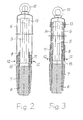
- the core 5 of the cable 4 is according to Fig. 2 surrounded by an existing metal wires, tensile reinforcement 6.
- the metal wires are advantageously made of galvanized steel. They can be designed as round or flat wires and are wrapped around the soul 5 as Umseilung.
- the reinforcement 6 is removed at the end of the cable 4 to a predetermined length, so that the core 5 is exposed on this length.
- a metal preferably made of stainless steel, existing pipe piece 7 is pushed, which rests tightly against the reinforcement 6.
- the core 5 is also surrounded in the illustrated embodiment by a clamping ring 8 made of metal, on which the metal wires of the reinforcement 6 rest. They lie in the mounting position between the clamping ring 8 and the pipe section 7 and are thereby clamped between these two parts.
- a metal preferably made of stainless steel
- existing, cup-shaped and tubular elongated sleeve 9 is arranged, which projects beyond the pipe section 7. It has at its free end a suitable for attaching a tension element device, which is designed as a drawbar eye 10 in the illustrated embodiment.
- the sleeve 9 has advantageously at its open end a fixedly connected to the same ring 11, which surrounds the end of the pipe section 7 in the mounting position.
- at least three screws 12 can be used, which distributed over the circumference of the ring 11, penetrate the same and extend into the pipe section 7.
- the ring 11 may for this purpose have a corresponding number of threaded bores and the pipe section 7 may have at the height of these threaded holes either holes or advantageously a circumferential groove.
- the ring 11 may also be provided with an internal thread which engages in an assembly position in an attached to the pipe section 7 external thread. As an additional assurance of the relative position of sleeve 9 and pipe section 7 to each other, the screws 12 can be attached. In both versions sleeve 9 and pipe section 7 are firmly connected.
- the end of the soul 5 may be covered by a cap 13.
- the metal wires of the reinforcement 6 are clamped between the pipe section 7 and the clamping ring 8, which advantageously have corresponding, conical bearing surfaces.
- the cable 4 can therefore be pulled in its longitudinal direction by a pulling element acting on the pipe section 7.
- a suitably high-tensile connection could also be created in that the pipe section 7 and the metal wires of the reinforcement 6 are welded together.
- the clamping ring 8 is not needed in this variant. However, it is also possible, when using the clamping ring 8 in the sense described in addition to weld the metal wires of the reinforcement 6 with the pipe section 7 and / or with the clamping ring 8.
- a tube which is corrugated transversely to its longitudinal direction is used as sleeve 9.
- the sleeve 9 is thus easily bendable.
- This embodiment of the device is advantageous if the reinforcement 6 is removed at a greater length from the end of the cable 1.
- the prefabricated using a corrugated tube as a sleeve 9 end of the cable 4 can thus be "wound up" when winding it on a coil, so that it does not protrude beyond the profile of the coil.
- a tensile layer 14 may be attached, which is designed for example as a braid of metal wires, which are advantageously made of stainless steel.
- the pipe section 7 has in a preferred embodiment on its outer surface parts of a fastening device whose complementary parts are attached to the platform 3.
- a fastening device for example, at least one circumferential groove 15 with preferably rectangular cross-section is mounted in the pipe section 7.
- Such a part of a fastening device has the advantage that it does not protrude beyond the profile of the pipe section 7 and thus does not interfere with the laying of the cable 4 as a bulky part.
- the method according to the invention is used to produce a device Fig. 2 for example, carried out as follows:
- the reinforcement 6 of the cable 4 is removed from the cable end at a predetermined length, possibly including the same surrounding layers.
- the cap 13 is placed on the core 5 of the cable 4.
- the pipe section 7 is pushed onto the cable end until it tightly surrounds the metal wires of the remaining reinforcement 6.
- the provided with a conical outer surface clamping ring 8 is pushed so far on the cable end until it engages under the metal wires of the reinforcement 6 and presses their ends until it rests against the conical inner surface of the pipe section 7. In this case, such acting in the axial direction pressure is exerted on the clamping ring 8, that the metal wires of the reinforcement 6 are clamped tensile strength.
- the metal wires of the reinforcement 6 can be additionally welded to the pipe section 7 and / or the clamping ring 8.
- the sleeve 9 is then plugged in a possible embodiment and connected by means of the ring 11 with the pipe section 7. This position is secured by at least three screws 12 - there are two screws 12 drawn - which penetrate the ring 11 and extend into the pipe section 7. The end of the cable 4 is then ready made.
- the described method can be carried out on a cable already wound onto a coil.
- the cable can also be wound on a spool only after completion of the tensile device.
- the cable 4 is pulled up in the sense described up to the platform 3 of a wind turbine and by a in Fig. 4 schematically indicated opening 16 of the same pulled.
- the cable end can then be determined via the pipe section 7 in the embodiment shown in the drawings advantageously by means of a two-part 17 and 18 retaining flange on the platform 3, which engage in the mounting position in the groove 15 of the pipe section 7.
- the parts 17 and 18 of the retaining flange are firmly connected to the platform 3.
- the sleeve 9 can then be removed from the cable 4, so that the soul 5, according to Fig. 4 can consist of three power cables, are available for electrical connection to appropriate devices.
Landscapes
- Engineering & Computer Science (AREA)
- Power Engineering (AREA)
- Life Sciences & Earth Sciences (AREA)
- Sustainable Development (AREA)
- Sustainable Energy (AREA)
- Chemical & Material Sciences (AREA)
- Combustion & Propulsion (AREA)
- Mechanical Engineering (AREA)
- General Engineering & Computer Science (AREA)
- Manufacturing & Machinery (AREA)
- Laying Of Electric Cables Or Lines Outside (AREA)
- Installation Of Indoor Wiring (AREA)
Priority Applications (4)
| Application Number | Priority Date | Filing Date | Title |
|---|---|---|---|
| EP14305321.3A EP2916407A1 (fr) | 2014-03-06 | 2014-03-06 | Procédé de fermeture résistante à la traction de l'extrémité d'un câble d'énergie et dispositif ainsi fabriqué |
| US14/630,794 US9876291B2 (en) | 2014-03-06 | 2015-02-25 | Method for a tension proof closure of the end of an energy cable |
| CA2883261A CA2883261A1 (fr) | 2014-03-06 | 2015-02-25 | Procede de fermeture a l'epreuve de la tension d'une extremite d'un cable d'energie, et dispositif fabrique selon le procede |
| BR102015004664A BR102015004664A2 (pt) | 2014-03-06 | 2015-03-03 | método para um fechamento à prova de tensão da extremidade de um cabo de energia e dispositivo fabricado pelo método |
Applications Claiming Priority (1)
| Application Number | Priority Date | Filing Date | Title |
|---|---|---|---|
| EP14305321.3A EP2916407A1 (fr) | 2014-03-06 | 2014-03-06 | Procédé de fermeture résistante à la traction de l'extrémité d'un câble d'énergie et dispositif ainsi fabriqué |
Publications (1)
| Publication Number | Publication Date |
|---|---|
| EP2916407A1 true EP2916407A1 (fr) | 2015-09-09 |
Family
ID=50280333
Family Applications (1)
| Application Number | Title | Priority Date | Filing Date |
|---|---|---|---|
| EP14305321.3A Withdrawn EP2916407A1 (fr) | 2014-03-06 | 2014-03-06 | Procédé de fermeture résistante à la traction de l'extrémité d'un câble d'énergie et dispositif ainsi fabriqué |
Country Status (4)
| Country | Link |
|---|---|
| US (1) | US9876291B2 (fr) |
| EP (1) | EP2916407A1 (fr) |
| BR (1) | BR102015004664A2 (fr) |
| CA (1) | CA2883261A1 (fr) |
Cited By (2)
| Publication number | Priority date | Publication date | Assignee | Title |
|---|---|---|---|---|
| DE102017117018A1 (de) * | 2017-07-27 | 2019-01-31 | Hans Benkert | Kabelstrumpf, insbesondere für Windkraftanlagen |
| EP3471223A1 (fr) * | 2017-10-16 | 2019-04-17 | NKT GmbH & Co. KG | Outil de montage destiné au montage et / ou soudage d'une tête de traction de câble à ou d'un câble électrique, en particulier câble sous-marin |
Families Citing this family (2)
| Publication number | Priority date | Publication date | Assignee | Title |
|---|---|---|---|---|
| KR101954789B1 (ko) * | 2016-11-30 | 2019-05-17 | 두산중공업 주식회사 | 파이프 어셈블리를 이용한 플랫폼 고정식 풍력 발전 플랜트. |
| CN115313250B (zh) * | 2022-08-15 | 2023-07-25 | 北京建工集团有限责任公司 | 一种用于电线穿管的牵带工具 |
Citations (2)
| Publication number | Priority date | Publication date | Assignee | Title |
|---|---|---|---|---|
| GB2183402A (en) * | 1985-11-22 | 1987-06-03 | Pirelli General Plc | Armoured cables |
| US20100314151A1 (en) * | 2009-06-15 | 2010-12-16 | Peter William Worrall | Cable termination system |
Family Cites Families (2)
| Publication number | Priority date | Publication date | Assignee | Title |
|---|---|---|---|---|
| US5878851A (en) * | 1996-07-02 | 1999-03-09 | Lord Corporation | Controllable vibration apparatus |
| WO2012155934A1 (fr) * | 2011-05-19 | 2012-11-22 | Prysmian S.P.A. | Raccordement destiné à des câbles électriques et procédé de fabrication dudit raccordement |
-
2014
- 2014-03-06 EP EP14305321.3A patent/EP2916407A1/fr not_active Withdrawn
-
2015
- 2015-02-25 US US14/630,794 patent/US9876291B2/en not_active Expired - Fee Related
- 2015-02-25 CA CA2883261A patent/CA2883261A1/fr not_active Abandoned
- 2015-03-03 BR BR102015004664A patent/BR102015004664A2/pt not_active Application Discontinuation
Patent Citations (2)
| Publication number | Priority date | Publication date | Assignee | Title |
|---|---|---|---|---|
| GB2183402A (en) * | 1985-11-22 | 1987-06-03 | Pirelli General Plc | Armoured cables |
| US20100314151A1 (en) * | 2009-06-15 | 2010-12-16 | Peter William Worrall | Cable termination system |
Cited By (2)
| Publication number | Priority date | Publication date | Assignee | Title |
|---|---|---|---|---|
| DE102017117018A1 (de) * | 2017-07-27 | 2019-01-31 | Hans Benkert | Kabelstrumpf, insbesondere für Windkraftanlagen |
| EP3471223A1 (fr) * | 2017-10-16 | 2019-04-17 | NKT GmbH & Co. KG | Outil de montage destiné au montage et / ou soudage d'une tête de traction de câble à ou d'un câble électrique, en particulier câble sous-marin |
Also Published As
| Publication number | Publication date |
|---|---|
| BR102015004664A2 (pt) | 2015-12-01 |
| US9876291B2 (en) | 2018-01-23 |
| US20150255899A1 (en) | 2015-09-10 |
| CA2883261A1 (fr) | 2015-09-06 |
Similar Documents
| Publication | Publication Date | Title |
|---|---|---|
| EP1145397B1 (fr) | Procede pour poser des cables electriques entre une premiere installation d'energie eolienne au large des cotes et une seconde installation d'energie eolienne au large des cotes | |
| EP3639335B1 (fr) | Station de chargement | |
| EP2916407A1 (fr) | Procédé de fermeture résistante à la traction de l'extrémité d'un câble d'énergie et dispositif ainsi fabriqué | |
| DE102013005901A1 (de) | Erdungskabel, insbesondere Bahnerdungskabel zur Erdung von Eisenbahneinrichtungen | |
| DE3228239C2 (de) | Verfahren zum Anlaschen von Lichtwellenleiter-Kabeln an Hochspannungsseilen | |
| EP3064648A1 (fr) | Ponton sur une installation offshore, installation offshore comprenant un tel ponton et procede de montage du ponton | |
| EP3471223A1 (fr) | Outil de montage destiné au montage et / ou soudage d'une tête de traction de câble à ou d'un câble électrique, en particulier câble sous-marin | |
| EP3113310A1 (fr) | Borne pour cable et son procede de fabrication | |
| EP3966905A1 (fr) | Support de câble pour un câble d'une installation d'énergie éolienne et procédé | |
| DE29709748U1 (de) | Energieleiter | |
| EP0046544B1 (fr) | Procédé pour la connexion de câbles | |
| DE1450408A1 (de) | Endverbindung fuer Leitungen oder Schlaeuche | |
| DE1908996B2 (de) | Verbindungsmuffe für Fernmeldekabel | |
| EP2333904A1 (fr) | Dispositif de connexion électrique entre les conducteurs d'un cable fort courant et des fils de dérivation | |
| DE102009031807A1 (de) | Montierungsvorrichtung für eine Füllstandmessvorrichtung | |
| EP3406899A1 (fr) | Procédé de câblage d'une éolienne, système de câblage pour une éolienne ainsi qu'une éolienne | |
| DE3017195C2 (fr) | ||
| DE3739182C1 (de) | Verfahren zum Herstellen einer zugfesten Verkappung eines Kabels | |
| DE2635493A1 (de) | Markierungsvorrichtung fuer draehte | |
| DE112015004283T5 (de) | Längenänderungswerkzeug für beleuchtung | |
| DE2411156A1 (de) | Verfahren zum erstellen von elektrischen installationen und isoliermantelrohr zum ausueben des verfahrens | |
| DE2300465A1 (de) | Kabelverspleissungsmuffe | |
| WO2019137881A1 (fr) | Pale de rotor d'éolienne | |
| DE102018107312B3 (de) | Positioniervorrichtung für Kabel in einer Turmsektion einer Windenergieanlage und Verfahren zum Einlegen von Kabeln in eine Turmsektion mit einer solchen Positioniervorrichtung | |
| DE1490172B2 (de) | Verbindung von armierungsdraehten elektrischer kabel |
Legal Events
| Date | Code | Title | Description |
|---|---|---|---|
| PUAI | Public reference made under article 153(3) epc to a published international application that has entered the european phase |
Free format text: ORIGINAL CODE: 0009012 |
|
| 17P | Request for examination filed |
Effective date: 20141222 |
|
| AK | Designated contracting states |
Kind code of ref document: A1 Designated state(s): AL AT BE BG CH CY CZ DE DK EE ES FI FR GB GR HR HU IE IS IT LI LT LU LV MC MK MT NL NO PL PT RO RS SE SI SK SM TR |
|
| AX | Request for extension of the european patent |
Extension state: BA ME |
|
| STAA | Information on the status of an ep patent application or granted ep patent |
Free format text: STATUS: EXAMINATION IS IN PROGRESS |
|
| 17Q | First examination report despatched |
Effective date: 20170315 |
|
| RAP1 | Party data changed (applicant data changed or rights of an application transferred) |
Owner name: NEXANS |
|
| STAA | Information on the status of an ep patent application or granted ep patent |
Free format text: STATUS: EXAMINATION IS IN PROGRESS |
|
| STAA | Information on the status of an ep patent application or granted ep patent |
Free format text: STATUS: THE APPLICATION IS DEEMED TO BE WITHDRAWN |
|
| 18D | Application deemed to be withdrawn |
Effective date: 20210323 |