EP2916069B1 - Method for measuring thickness of boiler water tube - Google Patents
Method for measuring thickness of boiler water tube Download PDFInfo
- Publication number
- EP2916069B1 EP2916069B1 EP14820692.3A EP14820692A EP2916069B1 EP 2916069 B1 EP2916069 B1 EP 2916069B1 EP 14820692 A EP14820692 A EP 14820692A EP 2916069 B1 EP2916069 B1 EP 2916069B1
- Authority
- EP
- European Patent Office
- Prior art keywords
- boiler water
- water tube
- guide pipe
- thickness
- measuring
- Prior art date
- Legal status (The legal status is an assumption and is not a legal conclusion. Google has not performed a legal analysis and makes no representation as to the accuracy of the status listed.)
- Active
Links
- XLYOFNOQVPJJNP-UHFFFAOYSA-N water Substances O XLYOFNOQVPJJNP-UHFFFAOYSA-N 0.000 title claims description 256
- 238000000034 method Methods 0.000 title claims description 34
- 239000000523 sample Substances 0.000 claims description 89
- 238000007689 inspection Methods 0.000 claims description 34
- 230000006866 deterioration Effects 0.000 claims description 10
- 230000001678 irradiating effect Effects 0.000 claims description 5
- 238000005259 measurement Methods 0.000 description 22
- 238000004441 surface measurement Methods 0.000 description 11
- 230000003247 decreasing effect Effects 0.000 description 8
- 238000005520 cutting process Methods 0.000 description 6
- 238000007789 sealing Methods 0.000 description 4
- 239000002184 metal Substances 0.000 description 3
- 238000010586 diagram Methods 0.000 description 2
- 238000012986 modification Methods 0.000 description 2
- 230000004048 modification Effects 0.000 description 2
- 238000009826 distribution Methods 0.000 description 1
- 230000000694 effects Effects 0.000 description 1
- 238000012423 maintenance Methods 0.000 description 1
- 238000004904 shortening Methods 0.000 description 1
- 238000003466 welding Methods 0.000 description 1
Images

Classifications
-
- G—PHYSICS
- G01—MEASURING; TESTING
- G01N—INVESTIGATING OR ANALYSING MATERIALS BY DETERMINING THEIR CHEMICAL OR PHYSICAL PROPERTIES
- G01N29/00—Investigating or analysing materials by the use of ultrasonic, sonic or infrasonic waves; Visualisation of the interior of objects by transmitting ultrasonic or sonic waves through the object
- G01N29/04—Analysing solids
- G01N29/043—Analysing solids in the interior, e.g. by shear waves
-
- F—MECHANICAL ENGINEERING; LIGHTING; HEATING; WEAPONS; BLASTING
- F22—STEAM GENERATION
- F22B—METHODS OF STEAM GENERATION; STEAM BOILERS
- F22B37/00—Component parts or details of steam boilers
- F22B37/002—Component parts or details of steam boilers specially adapted for nuclear steam generators, e.g. maintenance, repairing or inspecting equipment not otherwise provided for
-
- F—MECHANICAL ENGINEERING; LIGHTING; HEATING; WEAPONS; BLASTING
- F22—STEAM GENERATION
- F22B—METHODS OF STEAM GENERATION; STEAM BOILERS
- F22B37/00—Component parts or details of steam boilers
- F22B37/02—Component parts or details of steam boilers applicable to more than one kind or type of steam boiler
- F22B37/10—Water tubes; Accessories therefor
- F22B37/18—Inserts, e.g. for receiving deposits from water
-
- G—PHYSICS
- G01—MEASURING; TESTING
- G01N—INVESTIGATING OR ANALYSING MATERIALS BY DETERMINING THEIR CHEMICAL OR PHYSICAL PROPERTIES
- G01N29/00—Investigating or analysing materials by the use of ultrasonic, sonic or infrasonic waves; Visualisation of the interior of objects by transmitting ultrasonic or sonic waves through the object
- G01N29/04—Analysing solids
-
- G—PHYSICS
- G01—MEASURING; TESTING
- G01B—MEASURING LENGTH, THICKNESS OR SIMILAR LINEAR DIMENSIONS; MEASURING ANGLES; MEASURING AREAS; MEASURING IRREGULARITIES OF SURFACES OR CONTOURS
- G01B17/00—Measuring arrangements characterised by the use of infrasonic, sonic or ultrasonic vibrations
- G01B17/02—Measuring arrangements characterised by the use of infrasonic, sonic or ultrasonic vibrations for measuring thickness
-
- G—PHYSICS
- G01—MEASURING; TESTING
- G01N—INVESTIGATING OR ANALYSING MATERIALS BY DETERMINING THEIR CHEMICAL OR PHYSICAL PROPERTIES
- G01N2291/00—Indexing codes associated with group G01N29/00
- G01N2291/04—Wave modes and trajectories
- G01N2291/044—Internal reflections (echoes), e.g. on walls or defects
Definitions
- the invention relates to a method for measuring a thickness of a boiler water tube(10a) by using insertion-type ultrasonic wave thickness measurement, which is performed, for example, as part of an examination of age deterioration of a boiler water tube (10a).
- insertion-type ultrasonic wave thickness measurement of the boiler water tube has been performed by using, for example, ultrasonic flaw detecting equipment disclosed in PTL 1.
- the insertion-type ultrasonic wave thickness measurement of the boiler water tube is performed in the following sequence. First, an inspection hole is provided by cutting a part of the boiler water tube and an ultrasonic flaw detecting probe is inserted in the boiler water tube through the inspection hole.
- the ultrasonic flaw detecting probe is moved in the boiler water tube while irradiating the inner circumferential surface of the boiler water tube with an ultrasonic wave from the ultrasonic flaw detecting probe at a right angle along a circumferential direction. Accordingly, a thickness distribution along the circumferential direction of the boiler water tube is obtained along a shaft center direction of the boiler water tube.
- PTL2 discloses a method for measuring the thickness of a boiler water tube by irradiating an inner circumferential surface of the boiler with an ultrasonic wave from an ultrasonic probe.
- a guide is formed on an end side of the boiler tube through which the ultrasonic probe is inserted.
- the ultrasonic probe is moved on the inner side of the boiler water tube while the thickness is being measured.
- the boiler tube is in a vertical state and the guide pipe is aligned with the axis of the boiler tube.
- the guide pipe is provided on a side surface of the boiler water tube in an angle between 5 and 60 degrees to the boiler water tube and comprises a closing member in the shape of a long bolt member. Further, the document does not disclose a branched guide pipe.
- PTL3 discloses the use of an ultrasonic probe through a guide pipe with a long bolt closing member.
- the guide pipe is provided at an angle approximately 45 degrees to the main tube.
- the branched pipe is plugged not by the closing member, but by a flowmeter.
- An object of the invention is to provide a method for measuring the thickness of a boiler water tube (10a) by the insertion-type ultrasonic wave thickness measurement capable of improving the working rate of the boiler by reducing incidental work accompanying the thickness measurement of the boiler water tube (10a) resulting in a considerable shortening of the work period required for the measurement.
- a method for measuring the thickness of a boiler water tube (10a) which measures the thickness of a boiler water tube (10a) by irradiating an inner circumferential surface of the boiler water tube (10a) with an ultrasonic wave from an ultrasonic probe (18) while moving the ultrasonic probe (18) inserted into the boiler water tube (10a), the method comprising:
- the ultrasonic probe can be inserted in the boiler water tube (10a) from the upper side.
- the boiler water tube (10a) in the method for measuring the thickness of a boiler water tube (10a), it is preferable that the boiler water tube (10a) is oriented vertically, the base side of the guide pipe (16) is connected by being inclined downward in an angular range of 5 degrees to 60 degrees with respect to an axial center of the boiler water tube (10a).
- the closing member (24) is a long bolt member. Accordingly, the ultrasonic probe (18) can be inserted into the boiler water tube (10a) from the lower side.
- the boiler water tube (10a) in the method for measuring the thickness of a boiler water tube (10a), it is preferable that the boiler water tube (10a) is oriented horizontally or in an inclined state.
- the closing member (24) is a long bolt member, and an air pocket is not formed (that is, an air pocket is prevented from being generated) at the base end of the guide pipe (16) when the bolt member (24) is screwed into the guide pipe (16). Accordingly, the ultrasonic probe (18) can be inserted in the boiler water tube (10a).
- the guide pipe (16) is provided to all or some of the boiler water tubes (10a) as a managing target.
- the guide pipe (16) in the method for measuring the thickness of a boiler water tube (10a), it is preferable that the guide pipe (16) has a linear shape.
- the method for measuring the thickness of a boiler water tube (10a) it is preferable that an examination of age deterioration of the boiler water tube (10a) is performed by comparing the measured thickness of the boiler water tube (10a) with reference data.
- a length of the bolt member (24) is set so that a part of a tip of the bolt member (24) is in contact with an edge of the inspection hole (17) on an inner circumferential surface side of the boiler water tube (10a).
- the ultrasonic probe (18) is moved up to a target position, in advance, in the boiler water tube (10a), and then the thickness of the boiler water tube (10a) is measured while the ultrasonic probe (18) is pulled back to the inspection hole (17) from the target position.
- a guide pipe (16) is provided to a boiler water tube (10a), and usually, the guide pipe (16) is blocked by attaching a closing member (24) to the guide pipe (16), thereby operating the boiler.
- the closing member is released from the guide pipe, and the ultrasonic probe can be inserted into the boiler water tube (10a) through the guide pipe (16).
- the ultrasonic probe (18) can be easily inserted into the boiler water tube (10a) from the upper side of the boiler water tube (10a) through the guide pipe (16), and the ultrasonic probe (18) can be easily taken out to the outside from the boiler water tube (10a) through the guide pipe (16).
- the closing member (24) is a long bolt member and an air pocket is not formed at the base end of the guide pipe (16) when the bolt member is screwed into the guide pipe (16), the operation efficiency of the boiler can be stable.
- the ultrasonic probe (18) can be easily inserted into the boiler water tube (10a) from the lower side of the boiler water tube (10a) through the guide pipe (16), and the ultrasonic probe (18) can be easily taken out to the outside from the boiler water tube (10a) through the guide pipe (16).
- the ultrasonic probe (18) can be easily inserted into the boiler water tube (10a) through guide pipe (16), and the ultrasonic probe (18) can be easily taken out to the outside from the boiler water tube (10a) through the guide pipe (16).
- the closing member (24) is a long bolt member, the bolt member is screwed into the guide pipe, and an air pocket is not formed at the base end of the guide pipe (16), the operation efficiency of the boiler can be stable.
- an examination of age deterioration of the boiler water tube (10a) can be performed by measuring the thickness of each of the boiler water tubes (10a).
- the guide pipe (16) is provided to some of the boiler water tubes (10a) as a managing target, the examination of age deterioration of the boiler water tube (10a) can be efficiently performed at low cost. Accordingly, it is possible to determine the effective period for regular inspection of the boiler and to perform efficient maintenance of the boiler water tube (10a).
- the attachment of the guide pipe (16) to the boiler water tube (10a) can be easily performed, and inserting and taking out the ultrasonic probe (18) into and from the boiler water tube (10a) can be easily performed.
- the examination of age deterioration of the boiler water tube (10a) is performed by comparing the measured thickness of the boiler water tube (10a) with reference data, since the thickness of the boiler water tube (10a) can be measured by performing the regular inspection of the boiler without the generation of incidental work, the examination of age deterioration can be easily and efficiently performed.
- a plurality of boiler water tubes (10) and (10a) are arranged in a boiler water tubes panel (11) in a vertical direction with gaps therebetween set in advance, and water passes through the inside of the boiler water tubes (10) and (10a).
- each of the boiler water tubes (10) and (10a) is suspended on a beam of a building. Therefore, the arrangement of the boiler water tubes (10) and (10a) in the boiler water tubes panel (11) is fixed.
- a header (14) communicates with an intermediate portion of each of the boiler water tubes (10) and (10a) in a longitudinal direction.
- a linear guide pipe (16) is attached to an end in the longitudinal direction of some boiler water tube (10a) (for example, arranged at a specific position in the boiler water tubes panel (11)) set as a managing target in the boiler water tubes (10) and (10a), for example, and to a side surface on the downstream side of an upper end plate (12).
- the position of the guide pipe (16) is not limited to the end in the longitudinal direction of the boiler water tubes (10) and (10a), and the guide pipe (16) can be attached to any position of the side surface in the longitudinal direction.
- the base side of the guide pipe (16) is fixed, by welding, to an inspection hole (17) that has a long-hole shape and is formed on the side surface of the boiler water tube (10a), by being inclined upward in a range of 5 degrees to 60 degrees with respect to an axial center of the boiler water tube (10a).
- a disc-shaped aligning member (20) is attached to an outer circumferential side of an ultrasonic probe (18) that is inserted into the boiler water tube (10a) through the guide pipe (16) when measuring the thickness of the boiler water tube (10a).
- the inner diameter of the guide pipe (16) is set to have the same dimension as, for example, the inner diameter of the boiler water tube (10a) due to the constraints that the aligning member (20) can pass through the guide pipe (16) and the guide pipe (16) can be easily connected to the boiler water tube (10a) through the inspection hole (17) formed on the boiler water tube (10a).
- the ultrasonic probe (18) can be easily inserted in the boiler water tube (10a) through the guide pipe (16). Further, in a case where inclination angle ⁇ of the guide pipe (16) with respect to the boiler water tube (10a) is less than 5 degrees, the dimension of a major axis D of the inspection hole (17) formed on the side surface of the boiler water tube (10a) is increased, which is not preferable.
- reference sign (21) indicates an acoustic mirror unit, and the acoustic mirror unit is rotatably attached to a tip end of the probe accommodating unit (19) so that the rotation central axis thereof matches the axial center position of the probe accommodating unit (19.)
- the acoustic mirror unit (21) rotates due to water flow passing through the probe accommodating unit (19), and has a function of changing the traveling direction of the ultrasonic wave radiated from a probe accommodated in the probe accommodating unit (19) along the central axis direction of the boiler water tube (10a), to the radially outward direction of the boiler water tube (10a).
- Reference sign (22) indicates a cable having flexibility, and the cable accommodates a signal cable of the probe and supplies water in the probe accommodating unit (19).
- Reference sign (23) indicates a flexible metal hose, and the flexible metal hose connects the probe accommodating unit (19) to the cable (22).
- the ultrasonic wave is radiated from the probe while the acoustic mirror unit (21) is rotated, the inner circumferential surface of the boiler water tube (10a) can be irradiated with the ultrasonic wave at a right angle along the circumferential direction. Further, a portion of the ultrasonic wave which is reflected by the inner circumferential surface of the boiler water tube (10a), is reflected again by the acoustic mirror unit (21), and is incident on the probe.
- the remainder of the ultrasonic wave enters the inside of the boiler water tube (10a), is reflected by the outer circumferential surface of the boiler water tube (10a), passes through the inside of the boiler water tube (10a), is reflected again by the acoustic mirror unit (21), and is incident on the probe.
- an inner-circumferential-surface measurement time until the ultrasonic wave radiated from the probe is reflected by the inner circumferential surface of the boiler water tube (10a) and is incident on the probe and an outer-circumferential-surface measurement time until the ultrasonic wave radiated from the probe is reflected by the outer circumferential surface of the boiler water tube (10a) and is incident on the probe are measured, and a measurement time difference is obtained. Therefore, it is possible to obtain the thickness of the boiler water tube (10a).
- the sound state of the boiler water tube (10a) means a state in which the thickness of the boiler water tube (10a) is not decreased (is not corroded). Further, in a case where the inner-circumferential-surface measurement time is longer than the inner-circumferential-surface sound time, it can be determined that the thickness on the inner circumferential surface side of the boiler water tube (10a) is decreased (corroded), and in a case where the outer-circumferential-surface sound time is shorter than the outer-circumferential-surface sound time, it can be determined that the thickness on outer circumferential surface side of the boiler water tube (10a) is decreased (corroded).
- a long bolt member (24) (an example of closing member (24)) is screwed into the guide pipe (16) from the tip side thereof, and thus the opening of the guide pipe (16) is blocked.
- the bolt member (24) includes a bolt body portion (26) on which a male screw that is screwed into a female screw unit (25) is formed on the inner surface on the tip side of the guide pipe (16); a bolt head portion (27) that is provided to be connected to the base side of the bolt body portion (26); and a cylindrical closing portion (28) that is provided to be connected to the tip side of the bolt body portion (26) and is fitted into a region on the base side closer than the female screw unit (25) in the guide pipe (16). Therefore, at the time of operating the boiler, the amount of bubbles present in water in the boiler water tube (10a) reaches a level that does not cause a problem in the management of the boiler.
- a stepped portion (29) that is opened to the outside is formed on the inner periphery of the tip of the guide pipe (16).
- a target of the examination for the age deterioration of the thickness of the boiler water tube (10a), that is, the boiler water tube (10a) as a managing target is selected in advance.
- the inspection hole (17) is formed on the side surface of an end of the boiler water tube (10a) in the longitudinal direction, in FIG. 1 , the side surface of the boiler water tube (10a) on the downstream side of the upper end plate (12), and the base side of the guide pipe (16) is connected to the inspection hole (17) by being inclined upward in a range of 5 degrees to 60 degrees with respect to an axial center of the boiler water tube (10a).
- the bolt member (24) is screwed into the guide pipe (16) from the tip side thereof and the opening of the guide pipe (16) is blocked. Further, in a case where the guide pipe (16) is blocked by the bolt member (24), the ring-shaped sealing member (30) is disposed on the bottom surface of the stepped portion (29) and then the screwing together is performed.
- the bolt member (24) that blocks the opening of the guide pipe (16) is released from the guide pipe (16) attached to the boiler water tube (10a). Then, water is poured in the boiler water tube (10a) and, as shown in FIG. 2 , the ultrasonic probe (18) is inserted into the guide pipe (16) from the tip side of the guide pipe (16). Then, the cable (22) is gradually fed into the guide pipe (16), and therefore, the ultrasonic probe (18) is caused to advance, thereby entering the boiler water tube (10a) by passing through the guide pipe (16).
- the ultrasonic probe (18) When the ultrasonic probe (18) is inserted into the boiler water tube (10a), the outer circumferential surface of the aligning member (20) of the ultrasonic probe (18) comes in contact with the inner circumferential surface of the boiler water tube (10a), and thereby, the axial center of the probe accommodating unit (19) is positioned at the axial center position of the boiler water tube (10a). Accordingly, the cable (22) is fed further into the guide pipe (16), and therefore, it is possible to move the ultrasonic probe (18) along the central axis of the boiler water tube (10a).
- the acoustic mirror unit (21) is rotated by supplying water into the ultrasonic probe (18) via the cable (22), ultrasonic wave is radiated from the probe, and the cable (22) is fed into the guide pipe (16) at a certain speed.
- the boiler water tube (10a) is filled with water, and thus when the thickness of the boiler water tube (10a) is measured, water is discharged from the tip portion of the guide pipe (16).
- the ultrasonic probe (18) is moved in the boiler water tube (10a) toward a target position on the side of a lower end plate (13) while irradiating the inner circumferential surface of the boiler water tube (10a) with an ultrasonic wave at a right angle along the circumferential direction. Accordingly, the trajectory of irradiated points of an ultrasonic wave radiated from the probe of the ultrasonic probe (18), on the inner circumferential surface of the boiler water tube (10a) is a spiral along the central axis of the boiler water tube (10a). Therefore, the inner-circumferential-surface measurement time and the outer-circumferential-surface measurement time are respectively obtained for the irradiated points positioned on the spiral.
- the measurement time difference between the outer-circumferential-surface measurement time and the inner-circumferential-surface measurement time is compared with the sound time difference, and it is determined whether or not the thickness of the boiler water tube (10a) is decreased for respective irradiated points.
- the thickness is decreased, based on the magnitude relationship of the inner-circumferential-surface measurement time and the inner-circumferential-surface sound time and the magnitude relationship of the outer-circumferential-surface measurement time and the outer-circumferential-surface sound time, it is determined whether the thickness is decreased on the inner circumferential surface side or the outer circumferential surface side, or on both of the inner and outer circumferential surface sides.
- the thickness is decreased at each irradiated point, and it is possible to obtain the status of the thickness decrease in the boiler water tube (10a). Further, by comparing reference data (that is, the inner-circumferential-surface sound time, the outer-circumferential-surface sound time, and the sound time difference) with the inner-circumferential-surface measurement time, the outer-circumferential-surface measurement time, and the measurement time difference, the examination of the age deterioration of the boiler water tube (10a) can be performed.
- reference data that is, the inner-circumferential-surface sound time, the outer-circumferential-surface sound time, and the sound time difference
- the ultrasonic probe (18) is moved up to the target position in the boiler water tube (10a) and the insertion-type ultrasonic wave thickness measurement of the boiler water tube (10a) is finished, the irradiation of an ultrasonic wave and the rotation of the acoustic mirror unit (21) are stopped.
- the cable (22) is gradually pulled out from the guide pipe (16), and the ultrasonic probe (18) is pulled back to the inspection hole (17).
- the ultrasonic probe (18) is guided in the guide pipe (16), and is taken out to the outside from the tip side of the guide pipe (16). Then, the opening of the guide pipe (16) is blocked by the bolt member (24).
- the thickness of the boiler water tube (10a) is measured while the ultrasonic probe (18) is moved up to the target position in the boiler water tube (10a); however, the ultrasonic probe (18) is first moved up to the target position, and then the thickness of the boiler water tube (10a) can be measured while the ultrasonic probe (18) is pulled back to the inspection hole (17).
- the guide pipe (16) is attached to the boiler water tube (10a), and usually, the opening of the guide pipe (16) is blocked by attaching the bolt member (24) to the guide pipe (16). Further, when the thickness of the boiler water tube (10a) is measured, the bolt member (24) is released from the guide pipe (16), and the ultrasonic probe (18) is inserted into the boiler water tube (10a) through the guide pipe (16). Accordingly, incidental work such as cutting the boiler water tube and restoring the boiler water tube after the thickness measurement, which is necessary for inserting the ultrasonic probe 18 into the boiler water tube in the related art, can be reduced, and thus the work period required for the regular inspection can be considerably shortened.
- the guide pipe is attached to the boiler water tube (10a) as a managing target, but the guide pipe can be attached to all of the boiler water tubes (10a).
- the shape of the guide pipe is a linear shape, but only the base part connected to the inspection hole is made to be bent in the range of 5 degrees to 60 degrees with respect to the boiler water tube (10a) and the other part can be made to be linear.
- the base side of the guide pipe is connected to the inspection hole by being inclined upward in the angular range of 5 degrees to 60 degrees with respect to an axial center of the boiler water tube (10a)oriented vertically, and the ultrasonic probe (18) is inserted from the upper side in the boiler water tube (10a) through the guide pipe (16).
- the base side of the guide pipe (16) can be connected to the inspection hole (17) by being inclined downward in the angular range of 5 degrees to 60 degrees with respect to an axial center of the boiler water tube (10a) oriented vertically, and the ultrasonic probe (18) can be inserted from the lower side into the boiler water tube (10a) through the guide pipe (16).
- the base side of the guide pipe (16) is connected to the inspection hole (17) by being inclined in the angular range of 5 degrees to 60 degrees with respect toan axial center of the boiler water tube (10a) oriented vertically, and the ultrasonic probe (18) is inserted into the boiler water tube (10a) through the guide pipe (16).
- the base side of the guide pipe (16) can be connected to the inspection hole (17) by being inclined in the angular range of 5 degrees to 60 degrees with respect toan axial center of the boiler water tube (10a) oriented horizontally or in an inclined state, and the ultrasonic probe (18) can be inserted into the boiler water tube (10a) through the guide pipe (16).
- a guide pipe (16) is provided to a boiler water tube (10a), and the guide pipe (16) is blocked by attaching a closing member (24) to the guide pipe (16), thereby operating the boiler.
- the closing member (24) is released from the guide pipe (16), and the ultrasonic probe (18) can be inserted into the boiler water tube (10a) through the guide pipe (16). Therefore, incidental work such as cutting the boiler water tube and restoring the boiler water tube after the thickness measurement, which is necessary in the related art, can be reduced, and thus a work period required for insertion-type ultrasonic wave thickness measurement of the boiler water tube (10a) can be considerably shortened. Further, since the work period required for the thickness measurement of the boiler water tube (10a) and the boiler restoration can be shortened, it is possible to easily cope with the emergency inspection of the boiler water tube (10a).
- the invention is industrially applicable.
Description
- The invention relates to a method for measuring a thickness of a boiler water tube(10a) by using insertion-type ultrasonic wave thickness measurement, which is performed, for example, as part of an examination of age deterioration of a boiler water tube (10a).
- In the related art, as part of an examination of age deterioration of a boiler water tube having a small diameter, insertion-type ultrasonic wave thickness measurement of the boiler water tube has been performed by using, for example, ultrasonic flaw detecting equipment disclosed in PTL 1. Here, the insertion-type ultrasonic wave thickness measurement of the boiler water tube is performed in the following sequence. First, an inspection hole is provided by cutting a part of the boiler water tube and an ultrasonic flaw detecting probe is inserted in the boiler water tube through the inspection hole. Next, the ultrasonic flaw detecting probe is moved in the boiler water tube while irradiating the inner circumferential surface of the boiler water tube with an ultrasonic wave from the ultrasonic flaw detecting probe at a right angle along a circumferential direction. Accordingly, a thickness distribution along the circumferential direction of the boiler water tube is obtained along a shaft center direction of the boiler water tube.
- PTL2 discloses a method for measuring the thickness of a boiler water tube by irradiating an inner circumferential surface of the boiler with an ultrasonic wave from an ultrasonic probe. A guide is formed on an end side of the boiler tube through which the ultrasonic probe is inserted. The ultrasonic probe is moved on the inner side of the boiler water tube while the thickness is being measured. The boiler tube is in a vertical state and the guide pipe is aligned with the axis of the boiler tube. The document does not disclose that the guide pipe is provided on a side surface of the boiler water tube in an angle between 5 and 60 degrees to the boiler water tube and comprises a closing member in the shape of a long bolt member. Further, the document does not disclose a branched guide pipe.
- PTL3 discloses the use of an ultrasonic probe through a guide pipe with a long bolt closing member. The guide pipe is provided at an angle approximately 45 degrees to the main tube. The branched pipe is plugged not by the closing member, but by a flowmeter.
-
- [PTL 1] Japanese Patent No.
3352653 - [PTL2]
JP S61 272602 - [PTL3]
JP 2005 338055 A - However, when the inspection hole is formed by cutting the boiler water tube, the boiler water tube is necessarily restored after the thickness measurement. Therefore, when performing the thickness measurement of the boiler water tube, it is necessary to secure a period of time required for incidental work such as cutting the boiler water tube and restoring the boiler water tube. As a result, a problem that the working rate of the boiler is decreased because a work period required for the thickness measurement of the boiler water tube becomes long arises.
- An object of the invention is to provide a method for measuring the thickness of a boiler water tube (10a) by the insertion-type ultrasonic wave thickness measurement capable of improving the working rate of the boiler by reducing incidental work accompanying the thickness measurement of the boiler water tube (10a) resulting in a considerable shortening of the work period required for the measurement.
- According to an aspect of the invention, there is provided a method for measuring the thickness of a boiler water tube (10a) which measures the thickness of a boiler water tube (10a) by irradiating an inner circumferential surface of the boiler water tube (10a) with an ultrasonic wave from an ultrasonic probe (18) while moving the ultrasonic probe (18) inserted into the boiler water tube (10a), the method comprising:
- forming an inspection hole (17) on a side surface of the boiler water tube (10a) in a longitudinal direction, and connecting a base side of a guide pipe (16) to the inspection hole (17);
- attaching a closing member (24) to the guide pipe (16);
- releasing the closing member (24) from the guide pipe (16);
- inserting the ultrasonic probe (18) into the boiler water tube (10a) from a tip side of the guide pipe (16), and moving the ultrasonic probe (18) in the boiler water tube (10a) when the thickness of the boiler water tube (10a) is measured;
- extracting the ultrasonic probe (18) from the boiler water tube (10a) after measuring the thickness of the boiler water tube (10a); and
- attaching the closing member (24) to the tip end of the guide pipe (16) after extracting the ultrasonic probe (18) from the boiler water tube (10a), wherein
- the boiler water tube (10a) is oriented vertically, horizontally or in an inclined state, the base side of the guide pipe (16) is connected by being inclined in an angular range of 5 degrees to 60 degrees with respect to an axial center of the boiler water tube (10a),
- the closing member (24) is a long bolt member screwed into the guide pipe (16) from the tip end thereof so as to fit with an inner circumference of the guide pipe (16), and
- the length of the closing member (24) is set so that a part of a tip of the bolt member (24) attached to the guide pipe (16) is in contact with an edge of the inspection hole (17) on an inner circumferential surface of the boiler water tube (10a), whereby an air pocket is not formed in the base end of the guide pipe (16).
- According to the aspect of the invention, in the method for measuring the thickness of a boiler water tube (10a), it is preferable that the boiler water tube (10a) is vertically oriented, the base side of the guide pipe (16) is connected by being inclined upward or downward in an angular range of 5 degrees to 60 degrees with respect to the axial center of the boiler water tube (10a)Accordingly, the ultrasonic probe can be inserted in the boiler water tube (10a) from the upper side.
- According to the aspect of the invention, in the method for measuring the thickness of a boiler water tube (10a), it is preferable that the boiler water tube (10a) is oriented vertically, the base side of the guide pipe (16) is connected by being inclined downward in an angular range of 5 degrees to 60 degrees with respect to an axial center of the boiler water tube (10a). The closing member (24) is a long bolt member. Accordingly, the ultrasonic probe (18) can be inserted into the boiler water tube (10a) from the lower side.
- According to the aspect of the invention, in the method for measuring the thickness of a boiler water tube (10a), it is preferable that the boiler water tube (10a) is oriented horizontally or in an inclined state. The closing member (24) is a long bolt member, and an air pocket is not formed (that is, an air pocket is prevented from being generated) at the base end of the guide pipe (16) when the bolt member (24) is screwed into the guide pipe (16). Accordingly, the ultrasonic probe (18) can be inserted in the boiler water tube (10a).
- According to the aspect of the invention, in the method for measuring the thickness of a boiler water tube (10a), it is preferable that a plurality of the boiler water tubes (10a) are provided, and the guide pipe (16) is provided to all or some of the boiler water tubes (10a) as a managing target.
- According to the aspect of the invention, in the method for measuring the thickness of a boiler water tube (10a), it is preferable that the guide pipe (16) has a linear shape.
- According to the aspect of the invention, in the method for measuring the thickness of a boiler water tube (10a), it is preferable that an examination of age deterioration of the boiler water tube (10a) is performed by comparing the measured thickness of the boiler water tube (10a) with reference data.
- According to the aspect of the invention, in the method for measuring the thickness of a boiler water tube (10a), it is preferable that, when the bolt member (24) is screwed into the guide pipe (16), a length of the bolt member (24) is set so that a part of a tip of the bolt member (24) is in contact with an edge of the inspection hole (17) on an inner circumferential surface side of the boiler water tube (10a).
- According to the aspect of the invention, in the method for measuring the thickness of a boiler water tube (10a), it is preferable that the ultrasonic probe (18) is moved up to a target position, in advance, in the boiler water tube (10a), and then the thickness of the boiler water tube (10a) is measured while the ultrasonic probe (18) is pulled back to the inspection hole (17) from the target position.
- According to the aspect of the method for measuring the thickness of a boiler water tube (10a), a guide pipe (16) is provided to a boiler water tube (10a), and usually, the guide pipe (16) is blocked by attaching a closing member (24) to the guide pipe (16), thereby operating the boiler. In addition, when the thickness of the boiler water tube (10a) is measured, the closing member is released from the guide pipe, and the ultrasonic probe can be inserted into the boiler water tube (10a) through the guide pipe (16). Therefore, incidental work such as cutting the boiler water tube and restoring the boiler water tube after the thickness measurement, which is necessary for inserting the ultrasonic probe into the boiler water tube in the related art, can be reduced, and thus a work period required for insertion-type ultrasonic wave thickness measurement of the boiler water tube (10a) can be considerably shortened. Further, since the work period required for the thickness measurement of the boiler water tube (10a) and the boiler restoration can be shortened, it is possible to easily cope with the emergency inspection of the boiler water tube (10a).
- In the aspect of the method for measuring the thickness of a boiler water tube (10a), in a case where the boiler water tube (10a) is oriented vertically, since the base side of the guide pipe (16) is connected by being inclined upward in an angular range of 5 degrees to 60 degrees with respect to an axial center of the boiler water tube (10a), the ultrasonic probe (18) can be easily inserted into the boiler water tube (10a) from the upper side of the boiler water tube (10a) through the guide pipe (16), and the ultrasonic probe (18) can be easily taken out to the outside from the boiler water tube (10a) through the guide pipe (16). In addition, since the closing member (24) is a long bolt member and an air pocket is not formed at the base end of the guide pipe (16) when the bolt member is screwed into the guide pipe (16), the operation efficiency of the boiler can be stable.
- In the aspect of the method for measuring the thickness of a boiler water tube (10a), in a case where the boiler water tube (10a) is oriented vertically, since the base side of the guide pipe (16) is connected by being inclined downward in an angular range of 5 degrees to 60 degrees with respect to an axial center of the boiler water tube (10a), and since the closing member (24) is a long bolt member, the ultrasonic probe (18) can be easily inserted into the boiler water tube (10a) from the lower side of the boiler water tube (10a) through the guide pipe (16), and the ultrasonic probe (18) can be easily taken out to the outside from the boiler water tube (10a) through the guide pipe (16).
- In the aspect of the method for measuring the thickness of a boiler water tube (10a), in a case where the boiler water tube (10a) is oriented horizontally or in an inclined state and since the base side of the guide pipe (16) is connected by being inclined in an angular range of 5 degrees to 60 degrees with respect to an axial center of the boiler water tube (10a), the ultrasonic probe (18) can be easily inserted into the boiler water tube (10a) through guide pipe (16), and the ultrasonic probe (18) can be easily taken out to the outside from the boiler water tube (10a) through the guide pipe (16). In addition, since the closing member (24) is a long bolt member, the bolt member is screwed into the guide pipe, and an air pocket is not formed at the base end of the guide pipe (16), the operation efficiency of the boiler can be stable.
- In the aspect of the method for measuring the thickness of a boiler water tube (10a), in a case where a plurality of the boiler water tubes (10a) are provided, and the guide pipe (16) is provided to all of the boiler water tubes (10a), an examination of age deterioration of the boiler water tube (10a) can be performed by measuring the thickness of each of the boiler water tubes (10a). In addition, in a case where the guide pipe (16) is provided to some of the boiler water tubes (10a) as a managing target, the examination of age deterioration of the boiler water tube (10a) can be efficiently performed at low cost. Accordingly, it is possible to determine the effective period for regular inspection of the boiler and to perform efficient maintenance of the boiler water tube (10a).
- In the aspect of the method for measuring the thickness of a boiler water tube (10a), in a case where the guide pipe (16) has a linear shape, the attachment of the guide pipe (16) to the boiler water tube (10a) can be easily performed, and inserting and taking out the ultrasonic probe (18) into and from the boiler water tube (10a) can be easily performed.
- In the aspect of the method for measuring the thickness of a boiler water tube (10a), in a case where the examination of age deterioration of the boiler water tube (10a) is performed by comparing the measured thickness of the boiler water tube (10a) with reference data, since the thickness of the boiler water tube (10a) can be measured by performing the regular inspection of the boiler without the generation of incidental work, the examination of age deterioration can be easily and efficiently performed.
-
-
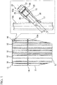
FIG. 1 is a diagram showing a boiler water tube (10a) to which a method for measuring the thickness of a boiler water tube (10a) according to an embodiment of the invention is applied. -
FIG. 2 is a diagram showing the method for measuring the thickness of the boiler water tube (10a). - For the understanding of the invention, a concrete embodiment of the invention will be described with reference to the accompanying drawings.
- First, description will be given of a boiler water tube (10a) oriented vertically and another boiler water tube (10) oriented vertically (refer to
FIG. 1 ), to which a method for measuring the thickness of a boiler water tube (10a) according to an embodiment of the invention is applied. - A plurality of boiler water tubes (10) and (10a) are arranged in a boiler water tubes panel (11) in a vertical direction with gaps therebetween set in advance, and water passes through the inside of the boiler water tubes (10) and (10a).
- An upper end of each of the boiler water tubes (10) and (10a) is suspended on a beam of a building. Therefore, the arrangement of the boiler water tubes (10) and (10a) in the boiler water tubes panel (11) is fixed.
- Further, a header (14) communicates with an intermediate portion of each of the boiler water tubes (10) and (10a) in a longitudinal direction. A linear guide pipe (16) is attached to an end in the longitudinal direction of some boiler water tube (10a) (for example, arranged at a specific position in the boiler water tubes panel (11)) set as a managing target in the boiler water tubes (10) and (10a), for example, and to a side surface on the downstream side of an upper end plate (12). The position of the guide pipe (16) is not limited to the end in the longitudinal direction of the boiler water tubes (10) and (10a), and the guide pipe (16) can be attached to any position of the side surface in the longitudinal direction. Hereinafter, the details thereof will be described.
- The base side of the guide pipe (16) is fixed, by welding, to an inspection hole (17) that has a long-hole shape and is formed on the side surface of the boiler water tube (10a), by being inclined upward in a range of 5 degrees to 60 degrees with respect to an axial center of the boiler water tube (10a). Here, as shown in
FIG 2 , a disc-shaped aligning member (20) is attached to an outer circumferential side of an ultrasonic probe (18) that is inserted into the boiler water tube (10a) through the guide pipe (16) when measuring the thickness of the boiler water tube (10a). When the ultrasonic probe (18) is inserted into the boiler water tube (10a), the outer circumferential surface of the aligning member (20) comes in contact with the inner circumferential surface of the boiler water tube (10a), and thereby, the central position of the ultrasonic probe (18) is maintained at the central position of the boiler water tube (10a). Therefore, the inner diameter of the guide pipe (16) is set to have the same dimension as, for example, the inner diameter of the boiler water tube (10a) due to the constraints that the aligning member (20) can pass through the guide pipe (16) and the guide pipe (16) can be easily connected to the boiler water tube (10a) through the inspection hole (17) formed on the boiler water tube (10a). - Since the inclination angle θ of the guide pipe (16) with respect to the boiler water tube (10a) is 5 degrees or more and 60 degrees or less, as shown in
FIG. 2 , the ultrasonic probe (18) can be easily inserted in the boiler water tube (10a) through the guide pipe (16). Further, in a case where inclination angle θ of the guide pipe (16) with respect to the boiler water tube (10a) is less than 5 degrees, the dimension of a major axis D of the inspection hole (17) formed on the side surface of the boiler water tube (10a) is increased, which is not preferable. Meanwhile, in a case where inclination angle θ of the guide pipe (16) with respect to the boiler water tube (10a) is more than 60 degrees, it is necessary to greatly change the traveling direction of the ultrasonic probe (18) when the ultrasonic probe (18) is inserted into the boiler water tube (10a) from the guide pipe (16), and it is difficult to manipulate the movement of the ultrasonic probe (18) because a plurality of (two inFIG. 2 ) disc-shaped aligning members (20) (which causes the axial center position of the probe accommodating unit (19) to match the axial center position of the boiler water tube (10a) are attached to the outer circumferential side of a probe accommodating unit (19) of the ultrasonic probe (18), which is not preferable. Further, in some circumstances, there is a problem in that the ultrasonic probe (18) cannot be inserted into the boiler water tube (10a). - Here, reference sign (21) indicates an acoustic mirror unit, and the acoustic mirror unit is rotatably attached to a tip end of the probe accommodating unit (19) so that the rotation central axis thereof matches the axial center position of the probe accommodating unit (19.) The acoustic mirror unit (21) rotates due to water flow passing through the probe accommodating unit (19), and has a function of changing the traveling direction of the ultrasonic wave radiated from a probe accommodated in the probe accommodating unit (19) along the central axis direction of the boiler water tube (10a), to the radially outward direction of the boiler water tube (10a). Reference sign (22) indicates a cable having flexibility, and the cable accommodates a signal cable of the probe and supplies water in the probe accommodating unit (19). Reference sign (23) indicates a flexible metal hose, and the flexible metal hose connects the probe accommodating unit (19) to the cable (22). In this configuration, if the ultrasonic wave is radiated from the probe while the acoustic mirror unit (21) is rotated, the inner circumferential surface of the boiler water tube (10a) can be irradiated with the ultrasonic wave at a right angle along the circumferential direction. Further, a portion of the ultrasonic wave which is reflected by the inner circumferential surface of the boiler water tube (10a), is reflected again by the acoustic mirror unit (21), and is incident on the probe. In addition, the remainder of the ultrasonic wave enters the inside of the boiler water tube (10a), is reflected by the outer circumferential surface of the boiler water tube (10a), passes through the inside of the boiler water tube (10a), is reflected again by the acoustic mirror unit (21), and is incident on the probe.
- Accordingly, an inner-circumferential-surface measurement time until the ultrasonic wave radiated from the probe is reflected by the inner circumferential surface of the boiler water tube (10a) and is incident on the probe, and an outer-circumferential-surface measurement time until the ultrasonic wave radiated from the probe is reflected by the outer circumferential surface of the boiler water tube (10a) and is incident on the probe are measured, and a measurement time difference is obtained. Therefore, it is possible to obtain the thickness of the boiler water tube (10a). Here, in the boiler water tube (10a) in a sound state, an inner-circumferential-surface sound time until the ultrasonic wave radiated from the probe is reflected by the inner circumferential surface of the boiler water tube (10a) and is incident on the probe, and an outer-circumferential-surface sound time until the ultrasonic wave radiated from the probe is reflected by the outer circumferential surface of the boiler water tube (10a) and is incident on the probe are measured, and a sound time difference is obtained. Therefore, it is possible for the decrement of the thickness of the boiler water tube (10a) to be calculated based on the difference between the sound time difference and the measurement time difference. In the invention, the sound state of the boiler water tube (10a) means a state in which the thickness of the boiler water tube (10a) is not decreased (is not corroded). Further, in a case where the inner-circumferential-surface measurement time is longer than the inner-circumferential-surface sound time, it can be determined that the thickness on the inner circumferential surface side of the boiler water tube (10a) is decreased (corroded), and in a case where the outer-circumferential-surface sound time is shorter than the outer-circumferential-surface sound time, it can be determined that the thickness on outer circumferential surface side of the boiler water tube (10a) is decreased (corroded).
- As shown in
FIG. 1 , a long bolt member (24) (an example of closing member (24)) is screwed into the guide pipe (16) from the tip side thereof, and thus the opening of the guide pipe (16) is blocked. Here, the bolt member (24) includes a bolt body portion (26) on which a male screw that is screwed into a female screw unit (25) is formed on the inner surface on the tip side of the guide pipe (16); a bolt head portion (27) that is provided to be connected to the base side of the bolt body portion (26); and a cylindrical closing portion (28) that is provided to be connected to the tip side of the bolt body portion (26) and is fitted into a region on the base side closer than the female screw unit (25) in the guide pipe (16). Therefore, at the time of operating the boiler, the amount of bubbles present in water in the boiler water tube (10a) reaches a level that does not cause a problem in the management of the boiler. - Further, a stepped portion (29) that is opened to the outside is formed on the inner periphery of the tip of the guide pipe (16). By inserting the bolt member (24) in the guide pipe (16) and screwing the bolt body portion (26) together with the female screw unit (25) of the guide pipe (16), the bolt member (24) can be gradually moved in the guide pipe (16) toward the boiler water tube (10a), and the movement of the bolt member (24) can be stopped when the lower surface of the bolt head portion (27) comes in contact with the bottom surface of the stepped portion (29) via a ring-shaped sealing member (30) and a ring-shaped washer (30a). Accordingly, in a case where the lower surface of the bolt head portion (27) is in contact with the bottom surface of the stepped portion (29) via a ring-shaped sealing member (30) and a ring-shaped washer (30a), if the length of the closing portion (28) is set in advance so that a part of the tip of the closing portion (28) is in contact with the inner edge of the inspection hole (17) (edge on the inner circumferential surface of the boiler water tube (10a)), when the closing portion (28) is fitted into the guide pipe (16), the highest position of a space portion formed on the base side of the guide pipe (16) can be approximately aligned with the highest position of the inner circumferential surface of the inspection hole (17). Accordingly, at the time of operating the boiler, bubbles present in water in the boiler water tube (10a) are prevented from being collected in the space portion formed on the base side of the guide pipe (16), and thus it is possible to prevent an air pocket from being generated at the time of operating the boiler.
- Sequentially, the method for measuring the thickness of the boiler water tube (10a) according to the embodiment of the invention will be described.
- As shown in
FIG. 1 , among the boiler water tubes (10) and (10a) that are long and oriented vertically, a target of the examination for the age deterioration of the thickness of the boiler water tube (10a), that is, the boiler water tube (10a) as a managing target is selected in advance. Next, the inspection hole (17) is formed on the side surface of an end of the boiler water tube (10a) in the longitudinal direction, inFIG. 1 , the side surface of the boiler water tube (10a) on the downstream side of the upper end plate (12), and the base side of the guide pipe (16) is connected to the inspection hole (17) by being inclined upward in a range of 5 degrees to 60 degrees with respect to an axial center of the boiler water tube (10a). In addition, usually, that is, at the time of operating the boiler, the bolt member (24) is screwed into the guide pipe (16) from the tip side thereof and the opening of the guide pipe (16) is blocked. Further, in a case where the guide pipe (16) is blocked by the bolt member (24), the ring-shaped sealing member (30) is disposed on the bottom surface of the stepped portion (29) and then the screwing together is performed. - When the measurement of the thickness of the boiler water tube (10a) is performed during the regular inspection of the boiler, the bolt member (24) that blocks the opening of the guide pipe (16) is released from the guide pipe (16) attached to the boiler water tube (10a). Then, water is poured in the boiler water tube (10a) and, as shown in
FIG. 2 , the ultrasonic probe (18) is inserted into the guide pipe (16) from the tip side of the guide pipe (16). Then, the cable (22) is gradually fed into the guide pipe (16), and therefore, the ultrasonic probe (18) is caused to advance, thereby entering the boiler water tube (10a) by passing through the guide pipe (16). - When the ultrasonic probe (18) is inserted into the boiler water tube (10a), the outer circumferential surface of the aligning member (20) of the ultrasonic probe (18) comes in contact with the inner circumferential surface of the boiler water tube (10a), and thereby, the axial center of the probe accommodating unit (19) is positioned at the axial center position of the boiler water tube (10a). Accordingly, the cable (22) is fed further into the guide pipe (16), and therefore, it is possible to move the ultrasonic probe (18) along the central axis of the boiler water tube (10a). Then, while the acoustic mirror unit (21) is rotated by supplying water into the ultrasonic probe (18) via the cable (22), ultrasonic wave is radiated from the probe, and the cable (22) is fed into the guide pipe (16) at a certain speed. Here, the boiler water tube (10a) is filled with water, and thus when the thickness of the boiler water tube (10a) is measured, water is discharged from the tip portion of the guide pipe (16).
- The ultrasonic probe (18) is moved in the boiler water tube (10a) toward a target position on the side of a lower end plate (13) while irradiating the inner circumferential surface of the boiler water tube (10a) with an ultrasonic wave at a right angle along the circumferential direction. Accordingly, the trajectory of irradiated points of an ultrasonic wave radiated from the probe of the ultrasonic probe (18), on the inner circumferential surface of the boiler water tube (10a) is a spiral along the central axis of the boiler water tube (10a). Therefore, the inner-circumferential-surface measurement time and the outer-circumferential-surface measurement time are respectively obtained for the irradiated points positioned on the spiral. Then, the measurement time difference between the outer-circumferential-surface measurement time and the inner-circumferential-surface measurement time is compared with the sound time difference, and it is determined whether or not the thickness of the boiler water tube (10a) is decreased for respective irradiated points. In addition, when the thickness is decreased, based on the magnitude relationship of the inner-circumferential-surface measurement time and the inner-circumferential-surface sound time and the magnitude relationship of the outer-circumferential-surface measurement time and the outer-circumferential-surface sound time, it is determined whether the thickness is decreased on the inner circumferential surface side or the outer circumferential surface side, or on both of the inner and outer circumferential surface sides. Accordingly, it is determined whether the thickness is decreased at each irradiated point, and it is possible to obtain the status of the thickness decrease in the boiler water tube (10a). Further, by comparing reference data (that is, the inner-circumferential-surface sound time, the outer-circumferential-surface sound time, and the sound time difference) with the inner-circumferential-surface measurement time, the outer-circumferential-surface measurement time, and the measurement time difference, the examination of the age deterioration of the boiler water tube (10a) can be performed.
- If the ultrasonic probe (18) is moved up to the target position in the boiler water tube (10a) and the insertion-type ultrasonic wave thickness measurement of the boiler water tube (10a) is finished, the irradiation of an ultrasonic wave and the rotation of the acoustic mirror unit (21) are stopped. Next, the cable (22) is gradually pulled out from the guide pipe (16), and the ultrasonic probe (18) is pulled back to the inspection hole (17). Then, the ultrasonic probe (18) is guided in the guide pipe (16), and is taken out to the outside from the tip side of the guide pipe (16). Then, the opening of the guide pipe (16) is blocked by the bolt member (24).
- The thickness of the boiler water tube (10a) is measured while the ultrasonic probe (18) is moved up to the target position in the boiler water tube (10a); however, the ultrasonic probe (18) is first moved up to the target position, and then the thickness of the boiler water tube (10a) can be measured while the ultrasonic probe (18) is pulled back to the inspection hole (17).
- As described above, the guide pipe (16) is attached to the boiler water tube (10a), and usually, the opening of the guide pipe (16) is blocked by attaching the bolt member (24) to the guide pipe (16). Further, when the thickness of the boiler water tube (10a) is measured, the bolt member (24) is released from the guide pipe (16), and the ultrasonic probe (18) is inserted into the boiler water tube (10a) through the guide pipe (16). Accordingly, incidental work such as cutting the boiler water tube and restoring the boiler water tube after the thickness measurement, which is necessary for inserting the
ultrasonic probe 18 into the boiler water tube in the related art, can be reduced, and thus the work period required for the regular inspection can be considerably shortened. - As above, the invention has been described with reference to the embodiment, but the invention is not limited to the configuration described in the above embodiment, and includes other embodiments or modification examples that can be considered to be in the range of matters described in the claims.
- Further, components obtained by combining the components of the embodiment and the other embodiments or the modification examples are also included in the invention.
- For example, the guide pipe is attached to the boiler water tube (10a) as a managing target, but the guide pipe can be attached to all of the boiler water tubes (10a).
- In addition, in the embodiment, the shape of the guide pipe is a linear shape, but only the base part connected to the inspection hole is made to be bent in the range of 5 degrees to 60 degrees with respect to the boiler water tube (10a) and the other part can be made to be linear.
- In addition, the base side of the guide pipe is connected to the inspection hole by being inclined upward in the angular range of 5 degrees to 60 degrees with respect to an axial center of the boiler water tube (10a)oriented vertically, and the ultrasonic probe (18) is inserted from the upper side in the boiler water tube (10a) through the guide pipe (16). However, the base side of the guide pipe (16) can be connected to the inspection hole (17) by being inclined downward in the angular range of 5 degrees to 60 degrees with respect to an axial center of the boiler water tube (10a) oriented vertically, and the ultrasonic probe (18) can be inserted from the lower side into the boiler water tube (10a) through the guide pipe (16).
- Further, the base side of the guide pipe (16) is connected to the inspection hole (17) by being inclined in the angular range of 5 degrees to 60 degrees with respect toan axial center of the boiler water tube (10a) oriented vertically, and the ultrasonic probe (18) is inserted into the boiler water tube (10a) through the guide pipe (16). However, the base side of the guide pipe (16) can be connected to the inspection hole (17) by being inclined in the angular range of 5 degrees to 60 degrees with respect toan axial center of the boiler water tube (10a) oriented horizontally or in an inclined state, and the ultrasonic probe (18) can be inserted into the boiler water tube (10a) through the guide pipe (16).
- According to the invention, a guide pipe (16) is provided to a boiler water tube (10a), and the guide pipe (16) is blocked by attaching a closing member (24) to the guide pipe (16), thereby operating the boiler. In addition, when the thickness of the boiler water tube (10a) is measured, the closing member (24) is released from the guide pipe (16), and the ultrasonic probe (18) can be inserted into the boiler water tube (10a) through the guide pipe (16). Therefore, incidental work such as cutting the boiler water tube and restoring the boiler water tube after the thickness measurement, which is necessary in the related art, can be reduced, and thus a work period required for insertion-type ultrasonic wave thickness measurement of the boiler water tube (10a) can be considerably shortened. Further, since the work period required for the thickness measurement of the boiler water tube (10a) and the boiler restoration can be shortened, it is possible to easily cope with the emergency inspection of the boiler water tube (10a).
- Therefore, the invention is industrially applicable.
-
- 10,10a: BOILER WATER TUBE
- 11: BOILER WATER TUBES PANEL
- 12: UPPER END PLATE
- 13: LOWER END PLATE
- 14: HEADER
- 16: GUIDE PIPE
- 17: INSPECTION HOLE
- 18: ULTRASONIC PROBE
- 19: PROBE ACCOMMODATING UNIT
- 20: ALIGNING MEMBER
- 21: ACOUSTIC MIRROR UNIT
- 22: CABLE
- 23: FLEXIBLE METAL HOSE
- 24: BOLT MEMBER
- 25: FEMALE SCREW UNIT
- 26: BOLT BODY PORTION
- 27: BOLT HEAD PORTION
- 28: CLOSING PORTION
- 29: STEPPED PORTION
- 30: SEALING MEMBER
- 30a: WASHER
Claims (8)
- A method for measuring the thickness of a boiler water tube (10a) which measures the thickness of a boiler water tube (10a) by irradiating an inner circumferential surface of the boiler water tube (10a) with an ultrasonic wave from an ultrasonic probe (18) while moving the ultrasonic probe (18) inserted into the boiler water tube (10a), the method comprising:forming an inspection hole (17) on a side surface of the boiler water tube (10a) in a longitudinal direction, and connecting a base side of a guide pipe (16) to the inspection hole (17);attaching a closing member (24) to the guide pipe (16);releasing the closing member (24) from the guide pipe (16);inserting the ultrasonic probe (18) into the boiler water tube (10a) from a tip side of the guide pipe (16), and moving the ultrasonic probe (18) in the boiler water tube (10a) when the thickness of the boiler water tube (10a) is measured;extracting the ultrasonic probe (18) from the boiler water tube (10a) after measuring the thickness of the boiler water tube (10a); andattaching the closing member (24) to the tip end of the guide pipe (16) after extracting the ultrasonic probe (18) from the boiler water tube (10a), whereinthe boiler water tube (10a) is oriented vertically, horizontally or in an inclined state, the base side of the guide pipe (16) is connected by being inclined in an angular range of 5 degrees to 60 degrees with respect to an axial center of the boiler water tube (10a),the closing member (24) is a long bolt member screwed into the guide pipe (16) from the tip end thereof so as to fit with an inner circumference of the guide pipe (16), andthe length of the closing member (24) is set so that a part of a tip of the bolt member (24) attached to the guide pipe (16) is in contact with an edge of the inspection hole (17) on an inner circumferential surface of the boiler water tube (10a), whereby an air pocket is not formed in the base end of the guide pipe (16).
- The method for measuring the thickness of a boiler water tube (10a) according to claim 1, wherein
the boiler water tube (10a) is vertically oriented, and the base side of the guide pipe (16) is connected by being inclined upward or downward in the angular range of 5 degrees to 60 degrees with respect to the axial center of the boiler water tube (10a). - The method for measuring the thickness of a boiler water tube (10a) according to claim 1, wherein
the boiler water tube (10a) is oriented horizontally or in the inclined state, and the base side of the guide pipe (16) is connected by being inclined in the angular range of 5 degrees to 60 degrees with respect to the axial center of the boiler water tube (10a). - The method for measuring the thickness of a boiler water tube (10a) according to any one of Claims 1 to 3, wherein
a plurality of the boiler water tubes (10a) are provided, and the guide pipe (16) is provided to all or some of the boiler water tubes (10a) as a managing target. - The method for measuring the thickness of a boiler water tube (10a) according to any one of Claims 1 to 4, wherein
the guide pipe (16) has a linear shape. - The method for measuring the thickness of a boiler water tube (10a) according to any one of Claims 1 to 5, wherein
an examination of age deterioration of the boiler water tube (10a) is performed by comparing the measured thickness of the boiler water tube (10a) with reference data. - The method for measuring the thickness of a boiler water tube (10a) according to any one of Claims 1 to 6, wherein
when the bolt member (24) is screwed into the guide pipe (16), a length of the bolt member (24) is set so that a part of a tip of the bolt member (24) is in contact with an edge of the inspection hole (17) on an inner circumferential surface side of the boiler water tube (10a). - The method for measuring the thickness of a boiler water tube (10a) according to any one of Claims 1 to 7, wherein the closing member (24) includes:a bolt body portion (26) having a male screw to be screwed into a female screw part (25) formed in the guide pipe (16);a bolt head portion (27) provided to be connected to the base end of the bolt body portion (26); anda cylindrical closing portion (28) provided to be connected to the tip end of the bolt body portion (26) and is fitted into a region in the guide pipe (16) closer to the base end of the guide pipe (16) than the female screw part (25),wherein a part of a tip of the closing portion (28) fitted into the region is in contact with the edge of the inspection hole (17) on the inner circumferential surface of the boiler water tube (10a), whereby an air pocket is not formed in the base end of the guide pipe (16).
Applications Claiming Priority (2)
| Application Number | Priority Date | Filing Date | Title |
|---|---|---|---|
| JP2013138994A JP5957421B2 (en) | 2013-07-02 | 2013-07-02 | Boiler water pipe thickness measurement method |
| PCT/JP2014/052746 WO2015001812A1 (en) | 2013-07-02 | 2014-02-06 | Method for measuring thickness of boiler water tube |
Publications (3)
| Publication Number | Publication Date |
|---|---|
| EP2916069A1 EP2916069A1 (en) | 2015-09-09 |
| EP2916069A4 EP2916069A4 (en) | 2016-02-17 |
| EP2916069B1 true EP2916069B1 (en) | 2017-12-20 |
Family
ID=52143410
Family Applications (1)
| Application Number | Title | Priority Date | Filing Date |
|---|---|---|---|
| EP14820692.3A Active EP2916069B1 (en) | 2013-07-02 | 2014-02-06 | Method for measuring thickness of boiler water tube |
Country Status (11)
| Country | Link |
|---|---|
| US (1) | US20150316509A1 (en) |
| EP (1) | EP2916069B1 (en) |
| JP (1) | JP5957421B2 (en) |
| KR (2) | KR20150083923A (en) |
| CN (1) | CN105408688B (en) |
| CA (1) | CA2894522C (en) |
| IN (1) | IN2015DN04784A (en) |
| MX (1) | MX348931B (en) |
| PE (1) | PE20151309A1 (en) |
| TW (1) | TWI513954B (en) |
| WO (1) | WO2015001812A1 (en) |
Families Citing this family (4)
| Publication number | Priority date | Publication date | Assignee | Title |
|---|---|---|---|---|
| JP6165375B1 (en) * | 2017-02-24 | 2017-07-19 | 三菱重工環境・化学エンジニアリング株式会社 | Flexible tube support device |
| JP6368394B2 (en) * | 2017-03-17 | 2018-08-01 | 株式会社ユニバーサルエンターテインメント | Game machine |
| CN108722998A (en) * | 2018-04-20 | 2018-11-02 | 武汉大学深圳研究院 | A kind of ultrasonic dredger of pipeline fixed point and method |
| WO2024030129A1 (en) * | 2022-08-03 | 2024-02-08 | Massa Products Corporation | Position detection in hostile environments using reflected radiated energy |
Family Cites Families (33)
| Publication number | Priority date | Publication date | Assignee | Title |
|---|---|---|---|---|
| JPS5337982U (en) * | 1976-09-07 | 1978-04-03 | ||
| FR2507778A1 (en) * | 1981-06-10 | 1982-12-17 | Stein Industrie | CAP FOR OPENING ACCESS TO A CONTROL RADIOGRAPHIC SOURCE IN A PIPING OR AN APPARATUS |
| JPS60148804U (en) * | 1984-03-09 | 1985-10-03 | バブコツク日立株式会社 | nozzle device |
| JPS61272602A (en) * | 1985-05-28 | 1986-12-02 | Ishikawajima Harima Heavy Ind Co Ltd | Measuring instrument for thickness of boiler heat conduction tube |
| JPH0545341A (en) * | 1991-08-09 | 1993-02-23 | Mitsubishi Heavy Ind Ltd | Ultrasonic probe for flaw inspection of boiler tube |
| JP3345074B2 (en) * | 1993-03-02 | 2002-11-18 | バブコック日立株式会社 | How to make the inner surface inspection plug mounting base |
| JPH0850118A (en) * | 1994-08-08 | 1996-02-20 | Babcock Hitachi Kk | Inside-surface pitting detection device for boiler heat-transfer tube |
| JPH08271243A (en) * | 1995-03-29 | 1996-10-18 | Mitsubishi Heavy Ind Ltd | Device for measuring wall thickness from inside of tube |
| US5585786A (en) * | 1995-10-30 | 1996-12-17 | Midland Manufacturing Corp. | Optical tank-level gauge |
| DE19600097C1 (en) * | 1996-01-03 | 1997-07-31 | Siemens Ag | Method and device for determining a liquid level using ultrasonic pulses |
| JPH10238709A (en) * | 1997-02-24 | 1998-09-08 | Ishikawajima Harima Heavy Ind Co Ltd | Inspection nipple |
| TW325518B (en) * | 1997-06-24 | 1998-01-21 | Nanya Plastics Corp | Control method for stiff piping thickness by laser measurement |
| JP2000098086A (en) * | 1998-09-25 | 2000-04-07 | Toshiba Corp | Device for fixing gas |
| US6380516B1 (en) * | 1999-08-11 | 2002-04-30 | Mitsubishi Heavy Industries, Ltd. | Connecting clamp, connecting apparatus and connecting method |
| JP3352653B2 (en) | 1999-09-13 | 2002-12-03 | 新日本非破壊検査株式会社 | Ultrasonic flaw detector for pipes |
| JP2003254942A (en) * | 2002-02-28 | 2003-09-10 | Toshiba Corp | Pipe inspection device and pipe inspection method |
| US6772636B2 (en) * | 2002-11-06 | 2004-08-10 | Varco I/P, Inc. | Pipe flaw detector |
| JP4228907B2 (en) * | 2003-12-19 | 2009-02-25 | Jfeエンジニアリング株式会社 | In-pipe inspection method |
| JP4707088B2 (en) * | 2004-04-27 | 2011-06-22 | 愛知時計電機株式会社 | Ultrasonic flow meter |
| DE102004060065B4 (en) * | 2004-12-14 | 2016-10-20 | Robert Bosch Gmbh | Ultrasonic flow meter with guide elements |
| US7254987B2 (en) * | 2005-01-11 | 2007-08-14 | Johns Manville | Method and system for conducting an on-site measurement of the density of an insulation material |
| JP2009204370A (en) * | 2008-02-26 | 2009-09-10 | Mitsubishi Heavy Ind Ltd | Measuring method of pipe wall thickness and device |
| US8166823B2 (en) * | 2009-09-29 | 2012-05-01 | National Oilwell Varco, L.P. | Membrane-coupled ultrasonic probe system for detecting flaws in a tubular |
| US8286491B2 (en) * | 2009-11-19 | 2012-10-16 | Olympus Ndt | Ultrasonic internal rotating inspection probe that self-eliminates air bubbles |
| JP2012021631A (en) * | 2010-07-16 | 2012-02-02 | Mitsubishi Heavy Ind Ltd | Inspection hole plug |
| JP2012185105A (en) * | 2011-03-08 | 2012-09-27 | Hitachi-Ge Nuclear Energy Ltd | Ultrasonic plate thickness measuring apparatus |
| JP5829674B2 (en) * | 2011-03-14 | 2015-12-09 | Jxエンジニアリング株式会社 | Ultrasonic inspection apparatus for tube and ultrasonic inspection method for tube |
| CN102305607B (en) * | 2011-05-24 | 2013-03-06 | 华北电力大学 | Calibration method for measuring thickness of oxidation layer on inner wall of boiler tube by ultrasonic wave |
| JP5863412B2 (en) * | 2011-11-24 | 2016-02-16 | 三菱重工環境・化学エンジニアリング株式会社 | Ultrasonic wall thickness measurement method |
| JP6004636B2 (en) * | 2011-12-01 | 2016-10-12 | 三菱重工環境・化学エンジニアリング株式会社 | Ultrasonic wall thickness measurement system |
| JP5791485B2 (en) * | 2011-12-15 | 2015-10-07 | 三菱重工業株式会社 | Pipe insertion type ultrasonic flaw detector |
| EP4235114A3 (en) * | 2012-08-22 | 2023-10-25 | Apator Miitors ApS | A compact ultrasonic flow meter |
| CN102980539A (en) * | 2012-11-19 | 2013-03-20 | 河北省电力公司电力科学研究院 | Method for measuring thicknesses of metal layer and oxide layer of wall of boiler heating surface tube |
-
2013
- 2013-07-02 JP JP2013138994A patent/JP5957421B2/en active Active
-
2014
- 2014-02-06 KR KR1020157016832A patent/KR20150083923A/en active Application Filing
- 2014-02-06 IN IN4784DEN2015 patent/IN2015DN04784A/en unknown
- 2014-02-06 EP EP14820692.3A patent/EP2916069B1/en active Active
- 2014-02-06 CN CN201480003337.6A patent/CN105408688B/en active Active
- 2014-02-06 TW TW103103933A patent/TWI513954B/en active
- 2014-02-06 MX MX2015007661A patent/MX348931B/en active IP Right Grant
- 2014-02-06 US US14/650,133 patent/US20150316509A1/en not_active Abandoned
- 2014-02-06 CA CA2894522A patent/CA2894522C/en active Active
- 2014-02-06 WO PCT/JP2014/052746 patent/WO2015001812A1/en active Application Filing
- 2014-02-06 KR KR1020167029677A patent/KR20160127164A/en not_active Application Discontinuation
- 2014-02-06 PE PE2015001178A patent/PE20151309A1/en active IP Right Grant
Non-Patent Citations (1)
| Title |
|---|
| None * |
Also Published As
| Publication number | Publication date |
|---|---|
| EP2916069A1 (en) | 2015-09-09 |
| IN2015DN04784A (en) | 2015-07-17 |
| CN105408688A (en) | 2016-03-16 |
| EP2916069A4 (en) | 2016-02-17 |
| WO2015001812A1 (en) | 2015-01-08 |
| PE20151309A1 (en) | 2015-09-19 |
| CN105408688B (en) | 2017-03-22 |
| KR20160127164A (en) | 2016-11-02 |
| MX2015007661A (en) | 2015-12-15 |
| TWI513954B (en) | 2015-12-21 |
| KR20150083923A (en) | 2015-07-20 |
| JP5957421B2 (en) | 2016-07-27 |
| TW201502469A (en) | 2015-01-16 |
| US20150316509A1 (en) | 2015-11-05 |
| JP2015010813A (en) | 2015-01-19 |
| CA2894522C (en) | 2016-05-17 |
| CA2894522A1 (en) | 2015-01-08 |
| MX348931B (en) | 2017-07-03 |
Similar Documents
| Publication | Publication Date | Title |
|---|---|---|
| EP2916069B1 (en) | Method for measuring thickness of boiler water tube | |
| JP4357298B2 (en) | Device for remote inspection of steam generation tubes | |
| JP2018021321A (en) | Circularity measurement device | |
| JP6438716B2 (en) | Displacement measuring device | |
| JP2009210548A (en) | Continuity measuring device and continuity measurement method using the same | |
| JP5434548B2 (en) | Flow velocity distribution measuring method and flow velocity distribution measuring apparatus | |
| CN102798369A (en) | Tool for detecting coaxiality of large-diameter multi-disc long-span workpiece | |
| CN102632274A (en) | Online detection and correction system for small-diameter deep-hole drilling laser guidance | |
| BR112013003163A2 (en) | defect determination method on a wind turbine blade root fixture and measuring tool for defect determination on a wind turbine blade root fixture | |
| JP2010066070A (en) | System for monitoring in-conduit work device | |
| CN101793537B (en) | Sensor for embedded ultrasonic flowmeter and installation method thereof on pipeline | |
| Tse et al. | Design and implementation of automatic deformation monitoring system for the construction of railway tunnel: a case study in West Island line | |
| JP2006284248A (en) | Position measurement method and instrument for displacement meter | |
| JP2007170919A (en) | Method of measuring vibration of heat exchanger | |
| CN208155125U (en) | A kind of spherical steam accumulator with waveguide pipe guiding mechanism | |
| JP2012145399A (en) | Conduit line construction method, and pipe body and nuclear facility | |
| KR102112595B1 (en) | The inspection apparatus for stud bolt and installing method thereof | |
| JP2013108834A (en) | Method and apparatus for measuring hole path position | |
| CN109752380A (en) | Special tooling for pipeline internal weld seams quality examination | |
| JP2008209239A (en) | In-pipe investigation device | |
| JP5610300B2 (en) | Ultrasonic transmitter / receiver fixture, pipe flow monitoring device and pipe flow monitoring method using ultrasonic transmitter / receiver fixture | |
| JP2008175704A (en) | Method of evaluating integrity in boiler pipe and accessory pipe | |
| WO2018088259A1 (en) | Pipe inspection device | |
| US20200400169A1 (en) | Flow straightener design and installation | |
| CA2986983A1 (en) | System and method for nuclear reactor inspection |
Legal Events
| Date | Code | Title | Description |
|---|---|---|---|
| PUAI | Public reference made under article 153(3) epc to a published international application that has entered the european phase |
Free format text: ORIGINAL CODE: 0009012 |
|
| 17P | Request for examination filed |
Effective date: 20150601 |
|
| AK | Designated contracting states |
Kind code of ref document: A1 Designated state(s): AL AT BE BG CH CY CZ DE DK EE ES FI FR GB GR HR HU IE IS IT LI LT LU LV MC MK MT NL NO PL PT RO RS SE SI SK SM TR |
|
| AX | Request for extension of the european patent |
Extension state: BA ME |
|
| RA4 | Supplementary search report drawn up and despatched (corrected) |
Effective date: 20160118 |
|
| RIC1 | Information provided on ipc code assigned before grant |
Ipc: F22B 37/18 20060101ALI20160112BHEP Ipc: F22B 37/02 20060101AFI20160112BHEP Ipc: F22B 37/00 20060101ALI20160112BHEP Ipc: G01B 17/02 20060101ALI20160112BHEP Ipc: G01N 29/04 20060101ALI20160112BHEP |
|
| DAX | Request for extension of the european patent (deleted) | ||
| 17Q | First examination report despatched |
Effective date: 20161219 |
|
| GRAP | Despatch of communication of intention to grant a patent |
Free format text: ORIGINAL CODE: EPIDOSNIGR1 |
|
| INTG | Intention to grant announced |
Effective date: 20170726 |
|
| GRAS | Grant fee paid |
Free format text: ORIGINAL CODE: EPIDOSNIGR3 |
|
| GRAA | (expected) grant |
Free format text: ORIGINAL CODE: 0009210 |
|
| AK | Designated contracting states |
Kind code of ref document: B1 Designated state(s): AL AT BE BG CH CY CZ DE DK EE ES FI FR GB GR HR HU IE IS IT LI LT LU LV MC MK MT NL NO PL PT RO RS SE SI SK SM TR |
|
| REG | Reference to a national code |
Ref country code: GB Ref legal event code: FG4D |
|
| REG | Reference to a national code |
Ref country code: CH Ref legal event code: EP |
|
| REG | Reference to a national code |
Ref country code: IE Ref legal event code: FG4D |
|
| REG | Reference to a national code |
Ref country code: AT Ref legal event code: REF Ref document number: 956715 Country of ref document: AT Kind code of ref document: T Effective date: 20180115 |
|
| REG | Reference to a national code |
Ref country code: DE Ref legal event code: R096 Ref document number: 602014018923 Country of ref document: DE |
|
| REG | Reference to a national code |
Ref country code: SE Ref legal event code: TRGR |
|
| REG | Reference to a national code |
Ref country code: NL Ref legal event code: MP Effective date: 20171220 |
|
| PG25 | Lapsed in a contracting state [announced via postgrant information from national office to epo] |
Ref country code: FI Free format text: LAPSE BECAUSE OF FAILURE TO SUBMIT A TRANSLATION OF THE DESCRIPTION OR TO PAY THE FEE WITHIN THE PRESCRIBED TIME-LIMIT Effective date: 20171220 Ref country code: LT Free format text: LAPSE BECAUSE OF FAILURE TO SUBMIT A TRANSLATION OF THE DESCRIPTION OR TO PAY THE FEE WITHIN THE PRESCRIBED TIME-LIMIT Effective date: 20171220 Ref country code: NO Free format text: LAPSE BECAUSE OF FAILURE TO SUBMIT A TRANSLATION OF THE DESCRIPTION OR TO PAY THE FEE WITHIN THE PRESCRIBED TIME-LIMIT Effective date: 20180320 |
|
| REG | Reference to a national code |
Ref country code: LT Ref legal event code: MG4D |
|
| REG | Reference to a national code |
Ref country code: AT Ref legal event code: MK05 Ref document number: 956715 Country of ref document: AT Kind code of ref document: T Effective date: 20171220 |
|
| PG25 | Lapsed in a contracting state [announced via postgrant information from national office to epo] |
Ref country code: BG Free format text: LAPSE BECAUSE OF FAILURE TO SUBMIT A TRANSLATION OF THE DESCRIPTION OR TO PAY THE FEE WITHIN THE PRESCRIBED TIME-LIMIT Effective date: 20180320 Ref country code: LV Free format text: LAPSE BECAUSE OF FAILURE TO SUBMIT A TRANSLATION OF THE DESCRIPTION OR TO PAY THE FEE WITHIN THE PRESCRIBED TIME-LIMIT Effective date: 20171220 Ref country code: RS Free format text: LAPSE BECAUSE OF FAILURE TO SUBMIT A TRANSLATION OF THE DESCRIPTION OR TO PAY THE FEE WITHIN THE PRESCRIBED TIME-LIMIT Effective date: 20171220 Ref country code: GR Free format text: LAPSE BECAUSE OF FAILURE TO SUBMIT A TRANSLATION OF THE DESCRIPTION OR TO PAY THE FEE WITHIN THE PRESCRIBED TIME-LIMIT Effective date: 20180321 Ref country code: HR Free format text: LAPSE BECAUSE OF FAILURE TO SUBMIT A TRANSLATION OF THE DESCRIPTION OR TO PAY THE FEE WITHIN THE PRESCRIBED TIME-LIMIT Effective date: 20171220 |
|
| PG25 | Lapsed in a contracting state [announced via postgrant information from national office to epo] |
Ref country code: NL Free format text: LAPSE BECAUSE OF FAILURE TO SUBMIT A TRANSLATION OF THE DESCRIPTION OR TO PAY THE FEE WITHIN THE PRESCRIBED TIME-LIMIT Effective date: 20171220 |
|
| PG25 | Lapsed in a contracting state [announced via postgrant information from national office to epo] |
Ref country code: CZ Free format text: LAPSE BECAUSE OF FAILURE TO SUBMIT A TRANSLATION OF THE DESCRIPTION OR TO PAY THE FEE WITHIN THE PRESCRIBED TIME-LIMIT Effective date: 20171220 Ref country code: SK Free format text: LAPSE BECAUSE OF FAILURE TO SUBMIT A TRANSLATION OF THE DESCRIPTION OR TO PAY THE FEE WITHIN THE PRESCRIBED TIME-LIMIT Effective date: 20171220 Ref country code: EE Free format text: LAPSE BECAUSE OF FAILURE TO SUBMIT A TRANSLATION OF THE DESCRIPTION OR TO PAY THE FEE WITHIN THE PRESCRIBED TIME-LIMIT Effective date: 20171220 Ref country code: CY Free format text: LAPSE BECAUSE OF FAILURE TO SUBMIT A TRANSLATION OF THE DESCRIPTION OR TO PAY THE FEE WITHIN THE PRESCRIBED TIME-LIMIT Effective date: 20171220 Ref country code: ES Free format text: LAPSE BECAUSE OF FAILURE TO SUBMIT A TRANSLATION OF THE DESCRIPTION OR TO PAY THE FEE WITHIN THE PRESCRIBED TIME-LIMIT Effective date: 20171220 |
|
| PG25 | Lapsed in a contracting state [announced via postgrant information from national office to epo] |
Ref country code: IT Free format text: LAPSE BECAUSE OF FAILURE TO SUBMIT A TRANSLATION OF THE DESCRIPTION OR TO PAY THE FEE WITHIN THE PRESCRIBED TIME-LIMIT Effective date: 20171220 Ref country code: RO Free format text: LAPSE BECAUSE OF FAILURE TO SUBMIT A TRANSLATION OF THE DESCRIPTION OR TO PAY THE FEE WITHIN THE PRESCRIBED TIME-LIMIT Effective date: 20171220 Ref country code: IS Free format text: LAPSE BECAUSE OF FAILURE TO SUBMIT A TRANSLATION OF THE DESCRIPTION OR TO PAY THE FEE WITHIN THE PRESCRIBED TIME-LIMIT Effective date: 20180420 Ref country code: SM Free format text: LAPSE BECAUSE OF FAILURE TO SUBMIT A TRANSLATION OF THE DESCRIPTION OR TO PAY THE FEE WITHIN THE PRESCRIBED TIME-LIMIT Effective date: 20171220 Ref country code: AT Free format text: LAPSE BECAUSE OF FAILURE TO SUBMIT A TRANSLATION OF THE DESCRIPTION OR TO PAY THE FEE WITHIN THE PRESCRIBED TIME-LIMIT Effective date: 20171220 Ref country code: PL Free format text: LAPSE BECAUSE OF FAILURE TO SUBMIT A TRANSLATION OF THE DESCRIPTION OR TO PAY THE FEE WITHIN THE PRESCRIBED TIME-LIMIT Effective date: 20171220 |
|
| REG | Reference to a national code |
Ref country code: CH Ref legal event code: PL |
|
| REG | Reference to a national code |
Ref country code: DE Ref legal event code: R097 Ref document number: 602014018923 Country of ref document: DE |
|
| PG25 | Lapsed in a contracting state [announced via postgrant information from national office to epo] |
Ref country code: MC Free format text: LAPSE BECAUSE OF FAILURE TO SUBMIT A TRANSLATION OF THE DESCRIPTION OR TO PAY THE FEE WITHIN THE PRESCRIBED TIME-LIMIT Effective date: 20171220 |
|
| PLBE | No opposition filed within time limit |
Free format text: ORIGINAL CODE: 0009261 |
|
| STAA | Information on the status of an ep patent application or granted ep patent |
Free format text: STATUS: NO OPPOSITION FILED WITHIN TIME LIMIT |
|
| GBPC | Gb: european patent ceased through non-payment of renewal fee |
Effective date: 20180320 |
|
| REG | Reference to a national code |
Ref country code: IE Ref legal event code: MM4A |
|
| PG25 | Lapsed in a contracting state [announced via postgrant information from national office to epo] |
Ref country code: DK Free format text: LAPSE BECAUSE OF FAILURE TO SUBMIT A TRANSLATION OF THE DESCRIPTION OR TO PAY THE FEE WITHIN THE PRESCRIBED TIME-LIMIT Effective date: 20171220 Ref country code: LI Free format text: LAPSE BECAUSE OF NON-PAYMENT OF DUE FEES Effective date: 20180228 Ref country code: CH Free format text: LAPSE BECAUSE OF NON-PAYMENT OF DUE FEES Effective date: 20180228 Ref country code: LU Free format text: LAPSE BECAUSE OF NON-PAYMENT OF DUE FEES Effective date: 20180206 |
|
| REG | Reference to a national code |
Ref country code: FR Ref legal event code: ST Effective date: 20181031 |
|
| 26N | No opposition filed |
Effective date: 20180921 |
|
| PG25 | Lapsed in a contracting state [announced via postgrant information from national office to epo] |
Ref country code: IE Free format text: LAPSE BECAUSE OF NON-PAYMENT OF DUE FEES Effective date: 20180206 |
|
| PG25 | Lapsed in a contracting state [announced via postgrant information from national office to epo] |
Ref country code: SI Free format text: LAPSE BECAUSE OF FAILURE TO SUBMIT A TRANSLATION OF THE DESCRIPTION OR TO PAY THE FEE WITHIN THE PRESCRIBED TIME-LIMIT Effective date: 20171220 Ref country code: FR Free format text: LAPSE BECAUSE OF NON-PAYMENT OF DUE FEES Effective date: 20180228 Ref country code: GB Free format text: LAPSE BECAUSE OF NON-PAYMENT OF DUE FEES Effective date: 20180320 |
|
| PG25 | Lapsed in a contracting state [announced via postgrant information from national office to epo] |
Ref country code: MT Free format text: LAPSE BECAUSE OF NON-PAYMENT OF DUE FEES Effective date: 20180206 |
|
| PG25 | Lapsed in a contracting state [announced via postgrant information from national office to epo] |
Ref country code: TR Free format text: LAPSE BECAUSE OF FAILURE TO SUBMIT A TRANSLATION OF THE DESCRIPTION OR TO PAY THE FEE WITHIN THE PRESCRIBED TIME-LIMIT Effective date: 20171220 |
|
| PG25 | Lapsed in a contracting state [announced via postgrant information from national office to epo] |
Ref country code: PT Free format text: LAPSE BECAUSE OF FAILURE TO SUBMIT A TRANSLATION OF THE DESCRIPTION OR TO PAY THE FEE WITHIN THE PRESCRIBED TIME-LIMIT Effective date: 20171220 |
|
| PG25 | Lapsed in a contracting state [announced via postgrant information from national office to epo] |
Ref country code: MK Free format text: LAPSE BECAUSE OF NON-PAYMENT OF DUE FEES Effective date: 20171220 Ref country code: HU Free format text: LAPSE BECAUSE OF FAILURE TO SUBMIT A TRANSLATION OF THE DESCRIPTION OR TO PAY THE FEE WITHIN THE PRESCRIBED TIME-LIMIT; INVALID AB INITIO Effective date: 20140206 |
|
| PG25 | Lapsed in a contracting state [announced via postgrant information from national office to epo] |
Ref country code: AL Free format text: LAPSE BECAUSE OF FAILURE TO SUBMIT A TRANSLATION OF THE DESCRIPTION OR TO PAY THE FEE WITHIN THE PRESCRIBED TIME-LIMIT Effective date: 20171220 |
|
| PGFP | Annual fee paid to national office [announced via postgrant information from national office to epo] |
Ref country code: SE Payment date: 20230216 Year of fee payment: 10 Ref country code: BE Payment date: 20230216 Year of fee payment: 10 |
|
| PGFP | Annual fee paid to national office [announced via postgrant information from national office to epo] |
Ref country code: DE Payment date: 20240219 Year of fee payment: 11 |