EP2916046A1 - Seal with integral base material and die for manufacturing same - Google Patents
Seal with integral base material and die for manufacturing same Download PDFInfo
- Publication number
- EP2916046A1 EP2916046A1 EP13850936.9A EP13850936A EP2916046A1 EP 2916046 A1 EP2916046 A1 EP 2916046A1 EP 13850936 A EP13850936 A EP 13850936A EP 2916046 A1 EP2916046 A1 EP 2916046A1
- Authority
- EP
- European Patent Office
- Prior art keywords
- base material
- gasket
- seal
- rubber
- integrated type
- Prior art date
- Legal status (The legal status is an assumption and is not a legal conclusion. Google has not performed a legal analysis and makes no representation as to the accuracy of the status listed.)
- Granted
Links
- 239000000463 material Substances 0.000 title claims abstract description 120
- 238000004519 manufacturing process Methods 0.000 title claims description 13
- 239000013013 elastic material Substances 0.000 claims abstract description 18
- 238000002347 injection Methods 0.000 claims description 19
- 239000007924 injection Substances 0.000 claims description 19
- 239000002184 metal Substances 0.000 claims description 18
- 238000000465 moulding Methods 0.000 claims description 13
- 239000000446 fuel Substances 0.000 description 29
- 229920003002 synthetic resin Polymers 0.000 description 7
- 239000000057 synthetic resin Substances 0.000 description 7
- 239000007789 gas Substances 0.000 description 5
- 239000002737 fuel gas Substances 0.000 description 4
- 239000012528 membrane Substances 0.000 description 4
- 239000000498 cooling water Substances 0.000 description 3
- 239000003792 electrolyte Substances 0.000 description 3
- 230000002093 peripheral effect Effects 0.000 description 3
- 230000000694 effects Effects 0.000 description 2
- 238000007254 oxidation reaction Methods 0.000 description 2
- 230000001590 oxidative effect Effects 0.000 description 2
- YCKRFDGAMUMZLT-UHFFFAOYSA-N Fluorine atom Chemical compound [F] YCKRFDGAMUMZLT-UHFFFAOYSA-N 0.000 description 1
- UFHFLCQGNIYNRP-UHFFFAOYSA-N Hydrogen Chemical compound [H][H] UFHFLCQGNIYNRP-UHFFFAOYSA-N 0.000 description 1
- 230000002411 adverse Effects 0.000 description 1
- QVGXLLKOCUKJST-UHFFFAOYSA-N atomic oxygen Chemical compound [O] QVGXLLKOCUKJST-UHFFFAOYSA-N 0.000 description 1
- 238000006243 chemical reaction Methods 0.000 description 1
- 238000001816 cooling Methods 0.000 description 1
- 238000003487 electrochemical reaction Methods 0.000 description 1
- 229910052731 fluorine Inorganic materials 0.000 description 1
- 239000011737 fluorine Substances 0.000 description 1
- 238000010030 laminating Methods 0.000 description 1
- 239000007800 oxidant agent Substances 0.000 description 1
- 239000001301 oxygen Substances 0.000 description 1
- 229910052760 oxygen Inorganic materials 0.000 description 1
- 229920005597 polymer membrane Polymers 0.000 description 1
- 238000010248 power generation Methods 0.000 description 1
- 238000007789 sealing Methods 0.000 description 1
- 238000007493 shaping process Methods 0.000 description 1
- 239000007787 solid Substances 0.000 description 1
- XLYOFNOQVPJJNP-UHFFFAOYSA-N water Substances O XLYOFNOQVPJJNP-UHFFFAOYSA-N 0.000 description 1
Images



Classifications
-
- F—MECHANICAL ENGINEERING; LIGHTING; HEATING; WEAPONS; BLASTING
- F16—ENGINEERING ELEMENTS AND UNITS; GENERAL MEASURES FOR PRODUCING AND MAINTAINING EFFECTIVE FUNCTIONING OF MACHINES OR INSTALLATIONS; THERMAL INSULATION IN GENERAL
- F16J—PISTONS; CYLINDERS; SEALINGS
- F16J15/00—Sealings
- F16J15/02—Sealings between relatively-stationary surfaces
- F16J15/06—Sealings between relatively-stationary surfaces with solid packing compressed between sealing surfaces
- F16J15/10—Sealings between relatively-stationary surfaces with solid packing compressed between sealing surfaces with non-metallic packing
- F16J15/12—Sealings between relatively-stationary surfaces with solid packing compressed between sealing surfaces with non-metallic packing with metal reinforcement or covering
- F16J15/121—Sealings between relatively-stationary surfaces with solid packing compressed between sealing surfaces with non-metallic packing with metal reinforcement or covering with metal reinforcement
- F16J15/122—Sealings between relatively-stationary surfaces with solid packing compressed between sealing surfaces with non-metallic packing with metal reinforcement or covering with metal reinforcement generally parallel to the surfaces
-
- B—PERFORMING OPERATIONS; TRANSPORTING
- B29—WORKING OF PLASTICS; WORKING OF SUBSTANCES IN A PLASTIC STATE IN GENERAL
- B29C—SHAPING OR JOINING OF PLASTICS; SHAPING OF MATERIAL IN A PLASTIC STATE, NOT OTHERWISE PROVIDED FOR; AFTER-TREATMENT OF THE SHAPED PRODUCTS, e.g. REPAIRING
- B29C45/00—Injection moulding, i.e. forcing the required volume of moulding material through a nozzle into a closed mould; Apparatus therefor
- B29C45/14—Injection moulding, i.e. forcing the required volume of moulding material through a nozzle into a closed mould; Apparatus therefor incorporating preformed parts or layers, e.g. injection moulding around inserts or for coating articles
- B29C45/14336—Coating a portion of the article, e.g. the edge of the article
- B29C45/14344—Moulding in or through a hole in the article, e.g. outsert moulding
-
- B—PERFORMING OPERATIONS; TRANSPORTING
- B29—WORKING OF PLASTICS; WORKING OF SUBSTANCES IN A PLASTIC STATE IN GENERAL
- B29C—SHAPING OR JOINING OF PLASTICS; SHAPING OF MATERIAL IN A PLASTIC STATE, NOT OTHERWISE PROVIDED FOR; AFTER-TREATMENT OF THE SHAPED PRODUCTS, e.g. REPAIRING
- B29C45/00—Injection moulding, i.e. forcing the required volume of moulding material through a nozzle into a closed mould; Apparatus therefor
- B29C45/16—Making multilayered or multicoloured articles
- B29C45/1671—Making multilayered or multicoloured articles with an insert
-
- B—PERFORMING OPERATIONS; TRANSPORTING
- B29—WORKING OF PLASTICS; WORKING OF SUBSTANCES IN A PLASTIC STATE IN GENERAL
- B29C—SHAPING OR JOINING OF PLASTICS; SHAPING OF MATERIAL IN A PLASTIC STATE, NOT OTHERWISE PROVIDED FOR; AFTER-TREATMENT OF THE SHAPED PRODUCTS, e.g. REPAIRING
- B29C45/00—Injection moulding, i.e. forcing the required volume of moulding material through a nozzle into a closed mould; Apparatus therefor
- B29C45/17—Component parts, details or accessories; Auxiliary operations
- B29C45/26—Moulds
-
- H—ELECTRICITY
- H01—ELECTRIC ELEMENTS
- H01M—PROCESSES OR MEANS, e.g. BATTERIES, FOR THE DIRECT CONVERSION OF CHEMICAL ENERGY INTO ELECTRICAL ENERGY
- H01M8/00—Fuel cells; Manufacture thereof
- H01M8/02—Details
- H01M8/0202—Collectors; Separators, e.g. bipolar separators; Interconnectors
- H01M8/0267—Collectors; Separators, e.g. bipolar separators; Interconnectors having heating or cooling means, e.g. heaters or coolant flow channels
-
- H—ELECTRICITY
- H01—ELECTRIC ELEMENTS
- H01M—PROCESSES OR MEANS, e.g. BATTERIES, FOR THE DIRECT CONVERSION OF CHEMICAL ENERGY INTO ELECTRICAL ENERGY
- H01M8/00—Fuel cells; Manufacture thereof
- H01M8/02—Details
- H01M8/0271—Sealing or supporting means around electrodes, matrices or membranes
- H01M8/0273—Sealing or supporting means around electrodes, matrices or membranes with sealing or supporting means in the form of a frame
-
- H—ELECTRICITY
- H01—ELECTRIC ELEMENTS
- H01M—PROCESSES OR MEANS, e.g. BATTERIES, FOR THE DIRECT CONVERSION OF CHEMICAL ENERGY INTO ELECTRICAL ENERGY
- H01M8/00—Fuel cells; Manufacture thereof
- H01M8/02—Details
- H01M8/0271—Sealing or supporting means around electrodes, matrices or membranes
- H01M8/0276—Sealing means characterised by their form
-
- H—ELECTRICITY
- H01—ELECTRIC ELEMENTS
- H01M—PROCESSES OR MEANS, e.g. BATTERIES, FOR THE DIRECT CONVERSION OF CHEMICAL ENERGY INTO ELECTRICAL ENERGY
- H01M8/00—Fuel cells; Manufacture thereof
- H01M8/02—Details
- H01M8/0271—Sealing or supporting means around electrodes, matrices or membranes
- H01M8/028—Sealing means characterised by their material
- H01M8/0284—Organic resins; Organic polymers
-
- H—ELECTRICITY
- H01—ELECTRIC ELEMENTS
- H01M—PROCESSES OR MEANS, e.g. BATTERIES, FOR THE DIRECT CONVERSION OF CHEMICAL ENERGY INTO ELECTRICAL ENERGY
- H01M8/00—Fuel cells; Manufacture thereof
- H01M8/02—Details
- H01M8/0271—Sealing or supporting means around electrodes, matrices or membranes
- H01M8/0286—Processes for forming seals
-
- B—PERFORMING OPERATIONS; TRANSPORTING
- B29—WORKING OF PLASTICS; WORKING OF SUBSTANCES IN A PLASTIC STATE IN GENERAL
- B29C—SHAPING OR JOINING OF PLASTICS; SHAPING OF MATERIAL IN A PLASTIC STATE, NOT OTHERWISE PROVIDED FOR; AFTER-TREATMENT OF THE SHAPED PRODUCTS, e.g. REPAIRING
- B29C45/00—Injection moulding, i.e. forcing the required volume of moulding material through a nozzle into a closed mould; Apparatus therefor
- B29C45/14—Injection moulding, i.e. forcing the required volume of moulding material through a nozzle into a closed mould; Apparatus therefor incorporating preformed parts or layers, e.g. injection moulding around inserts or for coating articles
- B29C2045/1486—Details, accessories and auxiliary operations
- B29C2045/14967—Injecting through an opening of the insert
-
- B—PERFORMING OPERATIONS; TRANSPORTING
- B29—WORKING OF PLASTICS; WORKING OF SUBSTANCES IN A PLASTIC STATE IN GENERAL
- B29K—INDEXING SCHEME ASSOCIATED WITH SUBCLASSES B29B, B29C OR B29D, RELATING TO MOULDING MATERIALS OR TO MATERIALS FOR MOULDS, REINFORCEMENTS, FILLERS OR PREFORMED PARTS, e.g. INSERTS
- B29K2021/00—Use of unspecified rubbers as moulding material
-
- B—PERFORMING OPERATIONS; TRANSPORTING
- B29—WORKING OF PLASTICS; WORKING OF SUBSTANCES IN A PLASTIC STATE IN GENERAL
- B29K—INDEXING SCHEME ASSOCIATED WITH SUBCLASSES B29B, B29C OR B29D, RELATING TO MOULDING MATERIALS OR TO MATERIALS FOR MOULDS, REINFORCEMENTS, FILLERS OR PREFORMED PARTS, e.g. INSERTS
- B29K2715/00—Condition, form or state of preformed parts, e.g. inserts
-
- B—PERFORMING OPERATIONS; TRANSPORTING
- B29—WORKING OF PLASTICS; WORKING OF SUBSTANCES IN A PLASTIC STATE IN GENERAL
- B29L—INDEXING SCHEME ASSOCIATED WITH SUBCLASS B29C, RELATING TO PARTICULAR ARTICLES
- B29L2031/00—Other particular articles
- B29L2031/26—Sealing devices, e.g. packaging for pistons or pipe joints
- B29L2031/265—Packings, Gaskets
-
- Y—GENERAL TAGGING OF NEW TECHNOLOGICAL DEVELOPMENTS; GENERAL TAGGING OF CROSS-SECTIONAL TECHNOLOGIES SPANNING OVER SEVERAL SECTIONS OF THE IPC; TECHNICAL SUBJECTS COVERED BY FORMER USPC CROSS-REFERENCE ART COLLECTIONS [XRACs] AND DIGESTS
- Y02—TECHNOLOGIES OR APPLICATIONS FOR MITIGATION OR ADAPTATION AGAINST CLIMATE CHANGE
- Y02E—REDUCTION OF GREENHOUSE GAS [GHG] EMISSIONS, RELATED TO ENERGY GENERATION, TRANSMISSION OR DISTRIBUTION
- Y02E60/00—Enabling technologies; Technologies with a potential or indirect contribution to GHG emissions mitigation
- Y02E60/10—Energy storage using batteries
-
- Y—GENERAL TAGGING OF NEW TECHNOLOGICAL DEVELOPMENTS; GENERAL TAGGING OF CROSS-SECTIONAL TECHNOLOGIES SPANNING OVER SEVERAL SECTIONS OF THE IPC; TECHNICAL SUBJECTS COVERED BY FORMER USPC CROSS-REFERENCE ART COLLECTIONS [XRACs] AND DIGESTS
- Y02—TECHNOLOGIES OR APPLICATIONS FOR MITIGATION OR ADAPTATION AGAINST CLIMATE CHANGE
- Y02E—REDUCTION OF GREENHOUSE GAS [GHG] EMISSIONS, RELATED TO ENERGY GENERATION, TRANSMISSION OR DISTRIBUTION
- Y02E60/00—Enabling technologies; Technologies with a potential or indirect contribution to GHG emissions mitigation
- Y02E60/30—Hydrogen technology
- Y02E60/50—Fuel cells
-
- Y—GENERAL TAGGING OF NEW TECHNOLOGICAL DEVELOPMENTS; GENERAL TAGGING OF CROSS-SECTIONAL TECHNOLOGIES SPANNING OVER SEVERAL SECTIONS OF THE IPC; TECHNICAL SUBJECTS COVERED BY FORMER USPC CROSS-REFERENCE ART COLLECTIONS [XRACs] AND DIGESTS
- Y02—TECHNOLOGIES OR APPLICATIONS FOR MITIGATION OR ADAPTATION AGAINST CLIMATE CHANGE
- Y02P—CLIMATE CHANGE MITIGATION TECHNOLOGIES IN THE PRODUCTION OR PROCESSING OF GOODS
- Y02P70/00—Climate change mitigation technologies in the production process for final industrial or consumer products
- Y02P70/50—Manufacturing or production processes characterised by the final manufactured product
Definitions
- the present invention relates to a base material integrated type seal in which a gasket is integrally formed in a film, a sheet or a plate-like base material, for example, a seal for a fuel battery which is provided for sealing a flow path formed in each of fuel battery cells of a fuel battery stack, and further relates to a metal mold which is used for manufacturing the same.
- the fuel battery is used in a wide intended purpose from a fuel batter for a compact power supply having about several tens W to an automotive power supply of 100 kW class, by mainly forming a fuel battery cell obtained by pinching a power generating body which includes an MEA (membrane electrode assembly) provided with a pair of electrode layers in both surfaces of an electrolyte membrane by separators, and forming a stack structure by laminating the fuel battery cells.
- MEA membrane electrode assembly
- a fluorine-based solid polymer membrane is mainly used for the electrolyte membrane of the MEA, and a proton conductivity is demanded.
- the separator is formed a flow path for supplying fuel gas (hydrogen gas) and oxidant gas (air including oxygen) to the electrolyte membrane, and has an important role which transmits electrons generated in an anode side on the basis of an electrochemical reaction.
- Fig. 6 shows a conventional base material integrated type seal which is applied as a seal for a fuel battery, together with a part of the fuel battery.
- the base material integrated type seal 100 is constructed by integrally forming gaskets 102 and 102 which are made of a rubber-like elastic material (a rubber material or a synthetic resin material having a rubber-like elasticity) on both surfaces in a thickness direction of a film, a sheet or a plate-like base material 101 which is constructed by an MEA or a synthetic resin film arranged so as to surround an outer periphery of the MEA.
- a rubber-like elastic material a rubber material or a synthetic resin material having a rubber-like elasticity
- Each of the gaskets 102 is constructed by a flat base 102a which is bonded to a surface of the base material 101, and a seal lip 102b which is formed so as to protrude like a chevron from the base 102a.
- the base material integrated type seal 100 is interposed between outer peripheral portions of the separators 200 and 200 in the fuel battery cell, and the seal lips 102b and 102b in the gaskets 102 and 102 are brought into close contact with bottom surfaces of seal grooves 201 and 201 which are formed in the separators 200 and 200 in a compressed state, whereby the base material integrated type seal 100 achieves a seal function against the fuel gas, the oxidization gas or the cooling water.
- the bases 102a and 102a of the gaskets 102 and 102 have protruding portions 102c and 102c which protrude in their width direction.
- the protruding portions 102c and 102c are connected to each other via a filling layer 103 infilling a through hole 101 a which is provided in the base material 101.
- the gaskets 102 and 102 are connected to each other via the filling layer 103.
- the protruding portions 102c and 102c may be formed over a whole length of the base 102a.
- Figs. 7 and 8 show a metal mold 300 for manufacturing the base material integrated type seal 100 by integrally forming the gaskets 102 and 102 in the base material 101. More specifically, the base material integrated type seal 100 is obtained by setting the base material 101 within the metal mold 300 which is constructed by an upper mold 301 and a lower mold 302 so as to mold clamp, and filling a liquid-like rubber for molding from an injection gate 304 provided in the upper mold 301 into cavities 303 and 303 which are defined by the base material 101 and inner surfaces of the upper mold 301 and the lower mold 302 so as to bridge and cure.
- the through hole 101 a for shaping the molding liquid-like rubber injected from the injection gate 304 into the cavities 303 and 303 in both sides of the base material 101 is necessarily provided at a position which is deviated from the seal lips 102b and 102b while taking "sink" on the basis of a bridging and curing into consideration.
- the cavities 303 and 303 corresponding to the molding space have expansion portions 303a and 303a which form the protruding portion 102c of the base 102a in the gasket 102, and the injection gate 304 and the through hole 101 a of the base material 101 are provided at positions which correspond to the expansion portions 303a and 303a (refer to patent document 1).
- Patent Document 1 Japanese Unexamined Patent Publication No. 2011-96545
- the conventional base material integrated type seal 100 has the protruding portions 102c and 102c protruding in their width direction in the bases 102a and 102a of the gaskets 102 and 102, it is unavoidable to make the widths of the seal grooves 201 and 201 formed in the separators 200 and 200 for accommodating the gaskets 102 and 102 wider at the degree of the protruding portions 102c and 102c. As a result, there has been a problem that a power generation area surrounded by the seal grooves 201 and 201 becomes relatively smaller.
- the present invention is made by taking the above points into consideration, and a technical problem of the present invention is to achieve a space saving by making a width of a gasket as small as possible in a base material integrated type seal in which the gasket is integrally formed in a film, a sheet or a plate-like base material.
- a base material integrated type seal according to the invention of a first aspect has a film, a sheet or a plate-like base material, a gasket which is made of a rubber-like elastic material integrally provided in the base material, and a filling layer which is made of a rubber-like elastic material filled into a through hole provided in the base material, wherein the filling layer is structured such that a part of the filling layer is connected to the gasket and the other part protrudes out of the gasket while being approximately flush with the base material.
- the rubber-like elastic material is a rubber material or a synthetic resin material having a rubber-like elasticity.
- the gasket made of the rubber-like elastic material integrally provided in the base material is structured such as to be connected to the filling layer which is made of the rubber-like elastic material filled in the through hole provided in the base material. Further, the filling layer protrudes out of the gasket, however, is formed within the through hole provided in the base material so as to be approximately flush with the base material, that is, formed at a thickness which is approximately equal to the base material. As a result, a size in the width direction of the gasket is substantially small. Accordingly, the seal groove for accommodating the gasket in an installed state to the device is not necessarily set to be a width which can accommodate the filling layer. Therefore, it is possible to make the width of the seal groove small.
- a base material integrated type seal according to the invention of a second aspect is the structure described in the first aspect, wherein the gasket is provided in both sides in a thickness direction of the base material.
- the gaskets made of the rubber-like elastic material in both sides in the thickness direction of the base material are structured such as to be connected to each other via the filling layer which is made of the rubber-like elastic material filled in the through hole provided in the base material.
- a metal mold for manufacturing a base material integrated type seal according to the invention of a third aspect is a metal mold for obtaining the base material integrated type seal described in the first or second aspect by integrally forming the gasket made of the rubber-like elastic material in the film, the sheet or the plate-like base material, wherein the metal mold is constructed by a plurality of split molds, an injection gate is open between a plurality of split molds at a position which is spaced from the cavity, the injection gate injecting a liquid-like rubber for molding into a cavity which is defined between the base material and inner surfaces of the split molds in a state in which the base material is positioned and set between the split molds so as to be mold clamped, and the base material is positioned in such a manner that the through hole provided in the base material is communicated with both of the cavity and the injection gate.
- the through hole provided in the base material is communicated with both of the cavity which is defined between the base material and the inner surface of the split molds by the mold clamping, and the injection gate which is open between a plurality of split molds at the position which is spaced from the cavity. Therefore, in the case that the liquid-like rubber for molding is injected from the injection gate, the liquid-like rubber for molding is filled into the cavity via the through hole and is shaped.
- the bridged and cured portion of the liquid-like rubber for molding within the cavity forms the gasket which is made of the rubber-like elastic material integrally formed with the base material, and the bridged and cured portion of the liquid-like rubber for molding within the through hole forms the filling layer structured such that a part is connected to the gasket and the other part protrudes out of the gasket while being approximately flush with the base material.
- the metal mold for manufacturing the base material integrated type seal according to the present invention it is possible to obtain the base material integrated type seal which achieves the space saving by making the width of the gasket substantially smaller.
- Figs. 1 to 3 show a preferable embodiment in which a base material integrated type seal according to the present invention is applied as a seal for a fuel battery.
- the base material integrated type seal 1 is structured, as shown in Fig. 1 , such that gaskets 12 and 12 made of a rubber-like elastic material are integrally formed in both surfaces in a thickness direction of a base material 11 which is constructed by an MEA or a synthetic resin film (a synthetic resin plate) arranged in such a manner as to surround an outer periphery of the MEA.
- Each of the gaskets 12 is constructed by a flat base 12a which is bonded to a surface of the base material 11, and a seal lip 12b which is formed so as to protrude like a chevron from the base 12a.
- the base material integrated type seal 1 is interposed between outer peripheral portions of separators 2 and 2 in a fuel battery cell, and the seal lips 12b and 12b in the gaskets 12 and 12 are brought into close contact with bottom surfaces of seal grooves 21 and 21 formed in the separators 2 and 2 in a compressed state, as shown in Figs. 2 and 3 , whereby the base material integrated type seal 1 achieves a seal function against fuel gas, oxidizing gas or cooling water.
- a plurality of through holes 11 a are provided in the base material 11 at positions which are deviated in a width direction from the seal lip 12b of the gasket 12 at an appropriate distance along an extending direction of the gasket 12, a filling layer 13 constructed by a rubber-like elastic material is filled within the through hole 11 a, and the filling layer 13 is structured such that a part is connected to the bases 12a and 12a in the gaskets 12 and 12 and the other part protrudes out of the gaskets 12 and 12 so as to be approximately flush with the base material 11, that is, at an approximately equal thickness to the base material 11.
- the gaskets 12 and 12 in both sides of the base material 11 are connected to each other via the filling layer 13 which is protruded and formed so as to be approximately flush with the base material 11 at the appropriate distance from the bases 12a and 12a, that is, at the approximately equal thickness to the base material 11.
- Figs. 4 and 5 shows a preferable embodiment of a metal mold according to the present invention for manufacturing the base material integrated type seal 1 shown in Fig. 1 by integrally forming the baskets 12 and 12 in the base material 11.
- the metal mold 3 according to the embodiment is constructed by an upper mold 31 and a lower mold 32, and groove-like concave portions 31 a and 32a are formed in inner surfaces of the upper mold 31 and the lower mold 32, the groove-like concave portions 31 a and 32a forming cavities 33 and 33 for forming the gaskets 12 and 12 shown in Fig. 1 between both surfaces of the base material 11 positioned and set therebetween.
- the upper mold 31 and the lower mold 32 correspond to the split mold described in the third aspect.
- a plurality of injection gates 34 for injecting a liquid-like rubber for molding to the cavities 33 and 33 are provided in the upper mold 31, and the injection gate 34 is open between the upper mold 31 and the lower mold 32 at a position which is spaced from the groove-like concave portions 31 a and 32a (the cavities 33 and 33).
- a plurality of through holes 11 a are previously provided in the base material 11 at appropriate distances along an extending direction of the cavities 33 and 33. Further, the providing position of the through hole 11 a is set in such a manner that a part of the through hole is positioned between the cavities 33 and 33 and the other part protrudes in the width direction from between the cavities 33 and 33 in a state in which the base material 11 is positioned and set between the upper mold 31 and the lower mold 32.
- the providing position of the injection gate 34 provided in the upper mold 31 is set in such a manner as to be open toward each of the through holes 11 a of the base material 11 in the case that the base material 11 is positioned and set between the upper mold 31 and the lower mold 32.
- the base material 11 is first of all positioned and set between the upper mold 31 and the lower mold 32 so as to be mold clamped.
- the injection gate 34 provided in the upper mold 31 is open toward the through hole 11 a provided in the base material 11, and a part of the through hole 11 a is positioned between the cavities 33 and 33 which are defined between the base material 11 and the groove-like concave portions 31 a and 32a of the upper mold 31 and the lower mold 32 by mold clamping.
- the through hole 11 a is communicated with both of the cavities 33 and 33 and the injection gate 34.
- the molding liquid-like rubber injected from the injection gate 34 of the upper mold 31 is filled within the cavities 33 and 33 in both sides of the base material 11 via the through hole 11 a of the base material 11 and is shaped. Further, the portion that the liquid-like rubber for molding is bridged and cured within the cavities 33 and 33 is formed as the gaskets 12 and 12 which is made of the rubber-like elastic material, and is integrated with the base material 11, and the portion that the liquid-like rubber for molding is bridged and cured within the through hole 11 a is connected in its part to the gaskets 12 and 12 and is approximately flush with the base material 11 in its other part so as to be formed as the filling layer 13 which protrudes out of the gaskets 12 and 12, so that the base material integrated type seal 1 shown in Fig. 1 is obtained.
- the base material integrated type seal 1 in Fig. 1 which is manufactured as mentioned above is formed within the through hole 11 a which is provided in the base material 11 so as to be approximately flush with the base material 11, that is, at approximately the same thickness as the base material 11 although the filling layer 13 connecting the gaskets 12 and 12 in both sides of the base material 11 to each other protrudes out of the gaskets 12 and 12.
- the size in the width direction of the gaskets 12 and 12 is substantially small. Therefore, as shown in Fig.
- the seal grooves 21 and 21 of the separators 2 and 2 are not necessarily formed with the width which can accommodate a whole from the gaskets 12 and 12 to the filling layer 13, so that it is possible to make the width of the seal grooves 21 and 21 small.
- the base material 11 is the synthetic resin film (the synthetic resin plate) which is arranged so as to surround the MEA in the fuel battery cell or the outer periphery of the MEA, however, the present invention can be applied to the case that the base material 11 is the separator, the other films, the sheet or the plate-like member.
- the description is given on the assumption that the basket 12 is provided on both surfaces in the thickness direction of the base material 11, however, the present invention can be applied to the case that the gasket 12 is provided on one surface of the base material 11.
Landscapes
- Engineering & Computer Science (AREA)
- Manufacturing & Machinery (AREA)
- Mechanical Engineering (AREA)
- Sustainable Energy (AREA)
- Life Sciences & Earth Sciences (AREA)
- Sustainable Development (AREA)
- Chemical & Material Sciences (AREA)
- Chemical Kinetics & Catalysis (AREA)
- Electrochemistry (AREA)
- General Chemical & Material Sciences (AREA)
- General Engineering & Computer Science (AREA)
- Fuel Cell (AREA)
- Gasket Seals (AREA)
- Moulds For Moulding Plastics Or The Like (AREA)
Abstract
Description
- The present invention relates to a base material integrated type seal in which a gasket is integrally formed in a film, a sheet or a plate-like base material, for example, a seal for a fuel battery which is provided for sealing a flow path formed in each of fuel battery cells of a fuel battery stack, and further relates to a metal mold which is used for manufacturing the same.
- The fuel battery is used in a wide intended purpose from a fuel batter for a compact power supply having about several tens W to an automotive power supply of 100 kW class, by mainly forming a fuel battery cell obtained by pinching a power generating body which includes an MEA (membrane electrode assembly) provided with a pair of electrode layers in both surfaces of an electrolyte membrane by separators, and forming a stack structure by laminating the fuel battery cells. A fluorine-based solid polymer membrane is mainly used for the electrolyte membrane of the MEA, and a proton conductivity is demanded. On the other hand, the separator is formed a flow path for supplying fuel gas (hydrogen gas) and oxidant gas (air including oxygen) to the electrolyte membrane, and has an important role which transmits electrons generated in an anode side on the basis of an electrochemical reaction.
- Further, in this kind of fuel battery, it is necessary to seal the fuel battery so as to prevent the fuel gas and the oxidization gas, water and surplus gas created by the reaction thereof, and cooling water for cooling the stack from leaking out to an external portion or being mixed with each other.
-
Fig. 6 shows a conventional base material integrated type seal which is applied as a seal for a fuel battery, together with a part of the fuel battery. The base material integratedtype seal 100 is constructed by integrally forminggaskets like base material 101 which is constructed by an MEA or a synthetic resin film arranged so as to surround an outer periphery of the MEA. Each of thegaskets 102 is constructed by aflat base 102a which is bonded to a surface of thebase material 101, and aseal lip 102b which is formed so as to protrude like a chevron from thebase 102a. Further, the base material integratedtype seal 100 is interposed between outer peripheral portions of theseparators seal lips gaskets seal grooves separators type seal 100 achieves a seal function against the fuel gas, the oxidization gas or the cooling water. - The
bases gaskets portions protruding portions filling layer 103 infilling a throughhole 101 a which is provided in thebase material 101. In other words, thegaskets filling layer 103. Theprotruding portions base 102a. -
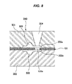
Figs. 7 and8 show ametal mold 300 for manufacturing the base material integratedtype seal 100 by integrally forming thegaskets base material 101. More specifically, the base material integratedtype seal 100 is obtained by setting thebase material 101 within themetal mold 300 which is constructed by anupper mold 301 and alower mold 302 so as to mold clamp, and filling a liquid-like rubber for molding from aninjection gate 304 provided in theupper mold 301 intocavities base material 101 and inner surfaces of theupper mold 301 and thelower mold 302 so as to bridge and cure. - The
through hole 101 a for shaping the molding liquid-like rubber injected from theinjection gate 304 into thecavities base material 101 is necessarily provided at a position which is deviated from theseal lips cavities expansion portions protruding portion 102c of thebase 102a in thegasket 102, and theinjection gate 304 and the throughhole 101 a of thebase material 101 are provided at positions which correspond to theexpansion portions - Patent Document 1: Japanese Unexamined Patent Publication No.
2011-96545 - However, since the conventional base material integrated
type seal 100 has the protrudingportions bases gaskets seal grooves separators gaskets portions seal grooves - The present invention is made by taking the above points into consideration, and a technical problem of the present invention is to achieve a space saving by making a width of a gasket as small as possible in a base material integrated type seal in which the gasket is integrally formed in a film, a sheet or a plate-like base material.
- As a means for effectively solving the technical problem mentioned above, a base material integrated type seal according to the invention of a first aspect has a film, a sheet or a plate-like base material, a gasket which is made of a rubber-like elastic material integrally provided in the base material, and a filling layer which is made of a rubber-like elastic material filled into a through hole provided in the base material, wherein the filling layer is structured such that a part of the filling layer is connected to the gasket and the other part protrudes out of the gasket while being approximately flush with the base material. The rubber-like elastic material is a rubber material or a synthetic resin material having a rubber-like elasticity.
- According to the structure of the first aspect, the gasket made of the rubber-like elastic material integrally provided in the base material is structured such as to be connected to the filling layer which is made of the rubber-like elastic material filled in the through hole provided in the base material. Further, the filling layer protrudes out of the gasket, however, is formed within the through hole provided in the base material so as to be approximately flush with the base material, that is, formed at a thickness which is approximately equal to the base material. As a result, a size in the width direction of the gasket is substantially small. Accordingly, the seal groove for accommodating the gasket in an installed state to the device is not necessarily set to be a width which can accommodate the filling layer. Therefore, it is possible to make the width of the seal groove small.
- A base material integrated type seal according to the invention of a second aspect is the structure described in the first aspect, wherein the gasket is provided in both sides in a thickness direction of the base material.
- According to the structure of the second aspect, the gaskets made of the rubber-like elastic material in both sides in the thickness direction of the base material are structured such as to be connected to each other via the filling layer which is made of the rubber-like elastic material filled in the through hole provided in the base material.
- A metal mold for manufacturing a base material integrated type seal according to the invention of a third aspect is a metal mold for obtaining the base material integrated type seal described in the first or second aspect by integrally forming the gasket made of the rubber-like elastic material in the film, the sheet or the plate-like base material, wherein the metal mold is constructed by a plurality of split molds, an injection gate is open between a plurality of split molds at a position which is spaced from the cavity, the injection gate injecting a liquid-like rubber for molding into a cavity which is defined between the base material and inner surfaces of the split molds in a state in which the base material is positioned and set between the split molds so as to be mold clamped, and the base material is positioned in such a manner that the through hole provided in the base material is communicated with both of the cavity and the injection gate.
- According to the structure of the third aspect, in the case that the film, the sheet or the plate-like base material is positioned and set between a plurality of split molds so as to be mold clamped, the through hole provided in the base material is communicated with both of the cavity which is defined between the base material and the inner surface of the split molds by the mold clamping, and the injection gate which is open between a plurality of split molds at the position which is spaced from the cavity. Therefore, in the case that the liquid-like rubber for molding is injected from the injection gate, the liquid-like rubber for molding is filled into the cavity via the through hole and is shaped. Further, the bridged and cured portion of the liquid-like rubber for molding within the cavity forms the gasket which is made of the rubber-like elastic material integrally formed with the base material, and the bridged and cured portion of the liquid-like rubber for molding within the through hole forms the filling layer structured such that a part is connected to the gasket and the other part protrudes out of the gasket while being approximately flush with the base material.
- On the basis of the base material integrated type seal according to the present invention, it is possible to make the width of the gasket substantially small. As a result, it is possible to achieve a space saving.
- On the basis of the metal mold for manufacturing the base material integrated type seal according to the present invention, it is possible to obtain the base material integrated type seal which achieves the space saving by making the width of the gasket substantially smaller.
-
-
Fig. 1 is a perspective view of a substantial part cross section and shows a seal for a fuel battery as an embodiment of a base material integrated type seal according to the present invention; -
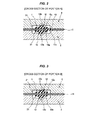
Fig. 2 is a cross sectional view of a substantial part and shows the seal for the fuel battery as the embodiment of the base material integrated type seal according to the present invention by cutting in a portion A inFig. 1 together with a part of the fuel battery; -
Fig. 3 is a cross sectional view of a substantial part and shows the seal for the fuel battery as the embodiment of the base material integrated type seal according to the present invention by cutting in a portion B inFig. 1 together with a part of the fuel battery; -
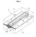
Fig. 4 is a perspective view of a substantial part cross section and shows a metal mold for manufacturing the seal for the fuel battery as the embodiment of the base material integrated type seal according to the present invention together with the manufactured fuel battery; -
Fig. 5 is a cross sectional view of a substantial part and shows the metal mold for manufacturing the seal for the fuel battery as the embodiment of the base material integrated type seal according to the present invention together with the positioned and set base material; -
Fig. 6 is a partly cross sectional view showing a conventional seal for a fuel battery together with a part of the fuel battery; -
Fig. 7 is a perspective view of a substantial part cross section and shows a metal mold for manufacturing the conventional seal for the fuel battery together with the manufactured seal for the fuel battery; and -
Fig. 8 is a partly cross sectional view showing the metal mold for manufacturing the conventional seal for the fuel battery together with the positioned and set base material. - A description will be given below of preferred embodiments of a base material integrated type seal and a metal mold for manufacturing the base material integrated type seal according to the present invention with reference to the accompanying drawings.
- First of all,
Figs. 1 to 3 show a preferable embodiment in which a base material integrated type seal according to the present invention is applied as a seal for a fuel battery. - The base material integrated
type seal 1 is structured, as shown inFig. 1 , such thatgaskets base material 11 which is constructed by an MEA or a synthetic resin film (a synthetic resin plate) arranged in such a manner as to surround an outer periphery of the MEA. Each of thegaskets 12 is constructed by aflat base 12a which is bonded to a surface of thebase material 11, and aseal lip 12b which is formed so as to protrude like a chevron from thebase 12a. Further, the base material integratedtype seal 1 is interposed between outer peripheral portions ofseparators seal lips gaskets seal grooves separators Figs. 2 and 3 , whereby the base material integratedtype seal 1 achieves a seal function against fuel gas, oxidizing gas or cooling water. - A plurality of through
holes 11 a are provided in thebase material 11 at positions which are deviated in a width direction from theseal lip 12b of thegasket 12 at an appropriate distance along an extending direction of thegasket 12, afilling layer 13 constructed by a rubber-like elastic material is filled within the throughhole 11 a, and thefilling layer 13 is structured such that a part is connected to thebases gaskets gaskets base material 11, that is, at an approximately equal thickness to thebase material 11. - Therefore, the
gaskets base material 11 are connected to each other via thefilling layer 13 which is protruded and formed so as to be approximately flush with thebase material 11 at the appropriate distance from thebases base material 11. -
Figs. 4 and5 shows a preferable embodiment of a metal mold according to the present invention for manufacturing the base material integratedtype seal 1 shown inFig. 1 by integrally forming thebaskets base material 11. Themetal mold 3 according to the embodiment is constructed by anupper mold 31 and alower mold 32, and groove-likeconcave portions upper mold 31 and thelower mold 32, the groove-likeconcave portions 32a forming cavities gaskets Fig. 1 between both surfaces of thebase material 11 positioned and set therebetween. Theupper mold 31 and thelower mold 32 correspond to the split mold described in the third aspect. - A plurality of
injection gates 34 for injecting a liquid-like rubber for molding to thecavities upper mold 31, and theinjection gate 34 is open between theupper mold 31 and thelower mold 32 at a position which is spaced from the groove-likeconcave portions cavities 33 and 33). - On the other hand, a plurality of through
holes 11 a are previously provided in thebase material 11 at appropriate distances along an extending direction of thecavities hole 11 a is set in such a manner that a part of the through hole is positioned between thecavities cavities base material 11 is positioned and set between theupper mold 31 and thelower mold 32. - Further, the providing position of the
injection gate 34 provided in theupper mold 31 is set in such a manner as to be open toward each of the throughholes 11 a of thebase material 11 in the case that thebase material 11 is positioned and set between theupper mold 31 and thelower mold 32. - Therefore, in order to manufacture the base material integrated
type seal 1 shown inFig. 1 by using themetal mold 3 having the structure mentioned above, thebase material 11 is first of all positioned and set between theupper mold 31 and thelower mold 32 so as to be mold clamped. At this time, theinjection gate 34 provided in theupper mold 31 is open toward the throughhole 11 a provided in thebase material 11, and a part of the throughhole 11 a is positioned between thecavities base material 11 and the groove-likeconcave portions upper mold 31 and thelower mold 32 by mold clamping. As a result, the throughhole 11 a is communicated with both of thecavities injection gate 34. - Therefore, in the mold clamping state mentioned above, the molding liquid-like rubber injected from the
injection gate 34 of theupper mold 31 is filled within thecavities base material 11 via the throughhole 11 a of thebase material 11 and is shaped. Further, the portion that the liquid-like rubber for molding is bridged and cured within thecavities gaskets base material 11, and the portion that the liquid-like rubber for molding is bridged and cured within the throughhole 11 a is connected in its part to thegaskets base material 11 in its other part so as to be formed as thefilling layer 13 which protrudes out of thegaskets type seal 1 shown inFig. 1 is obtained. - At this time, since the
injection gate 34 is at the position which is deviated from thecavities hole 11 a, it is possible to suppress an adverse effect caused by "sink" applied to the main body portion of thegaskets cavities - The base material integrated
type seal 1 inFig. 1 which is manufactured as mentioned above is formed within the throughhole 11 a which is provided in thebase material 11 so as to be approximately flush with thebase material 11, that is, at approximately the same thickness as thebase material 11 although thefilling layer 13 connecting thegaskets base material 11 to each other protrudes out of thegaskets gaskets 12 and 12 (thebases Fig. 2 , theseal grooves separators gaskets filling layer 13, so that it is possible to make the width of theseal grooves - Therefore, an occupied area of the
seal grooves seal grooves - In the embodiment mentioned above, the description is given on the assumption that the
base material 11 is the synthetic resin film (the synthetic resin plate) which is arranged so as to surround the MEA in the fuel battery cell or the outer periphery of the MEA, however, the present invention can be applied to the case that thebase material 11 is the separator, the other films, the sheet or the plate-like member. - Further, in the embodiment mentioned above, the description is given on the assumption that the
basket 12 is provided on both surfaces in the thickness direction of thebase material 11, however, the present invention can be applied to the case that thegasket 12 is provided on one surface of thebase material 11. -
- 1 base material integrated type seal
- 11 base material
- 11 a through hole
- 12 gasket
- 13 filling layer
- 2 separator
- 21 seal groove
- 3 metal mold
- 31 upper mold
- 32 lower mold
- 33 cavity
- 34 injection gate
Claims (3)
- A base material integrated type seal comprising:a film, a sheet or a plate-like base material;a gasket which is made of a rubber-like elastic material integrally provided in the base material; anda filling layer which is made of a rubber-like elastic material filled into a through hole provided in said base material,wherein the filling layer is structured such that a part of the filling layer is connected to said gasket and the other part protrudes out of said gasket approximately at the same thickness as said base material.
- The base material integrated type seal according to claim 1, wherein the gasket is provided in both sides in a thickness direction of the base material.
- A metal mold for manufacturing the base material integrated type seal according to claim 1 or 2 by integrally forming the gasket made of the rubber-like elastic material in the film, the sheet or the plate-like base material,
wherein the metal mold is constructed by a plurality of split molds, an injection gate is open between said plurality of split molds at a position which is spaced from said cavity, the injection gate injecting a liquid-like rubber for molding into a cavity which is defined between said base material and inner surfaces of said split molds in a state in which said base material is positioned and set between the split molds so as to be mold clamped, and said base material is positioned in such a manner that the through hole provided in the base material is communicated with both of said cavity and the injection gate.
Applications Claiming Priority (2)
| Application Number | Priority Date | Filing Date | Title |
|---|---|---|---|
| JP2012241597A JP2014092191A (en) | 2012-11-01 | 2012-11-01 | Base material integrated type seal and metal mold for manufacturing the same |
| PCT/JP2013/077202 WO2014069172A1 (en) | 2012-11-01 | 2013-10-07 | Seal with integral base material and die for manufacturing same |
Publications (3)
| Publication Number | Publication Date |
|---|---|
| EP2916046A1 true EP2916046A1 (en) | 2015-09-09 |
| EP2916046A4 EP2916046A4 (en) | 2015-11-18 |
| EP2916046B1 EP2916046B1 (en) | 2018-12-12 |
Family
ID=50627088
Family Applications (1)
| Application Number | Title | Priority Date | Filing Date |
|---|---|---|---|
| EP13850936.9A Active EP2916046B1 (en) | 2012-11-01 | 2013-10-07 | Seal with integral base material and method for manufacturing same |
Country Status (6)
| Country | Link |
|---|---|
| US (1) | US10103364B2 (en) |
| EP (1) | EP2916046B1 (en) |
| JP (1) | JP2014092191A (en) |
| KR (1) | KR20150079702A (en) |
| CN (1) | CN104755818B (en) |
| WO (1) | WO2014069172A1 (en) |
Cited By (4)
| Publication number | Priority date | Publication date | Assignee | Title |
|---|---|---|---|---|
| WO2016130781A1 (en) * | 2015-02-12 | 2016-08-18 | Ballard Power Systems Inc. | Seal for solid polymer electrolyte fuel cell |
| EP4015964A1 (en) * | 2020-12-16 | 2022-06-22 | Danfoss A/S | Gasket unit insert for heat exchanger |
| EP3534045B1 (en) * | 2016-10-27 | 2023-01-25 | NOK Corporation | Gasket and method for manufacturing same |
| FR3157682A1 (en) * | 2023-12-26 | 2025-06-27 | Symbio France | Peripheral seal, polar separator comprising such a seal, electrochemical cell comprising such a separator, fuel cell comprising such a cell and vehicle comprising such a cell |
Families Citing this family (14)
| Publication number | Priority date | Publication date | Assignee | Title |
|---|---|---|---|---|
| JP2014183102A (en) * | 2013-03-18 | 2014-09-29 | Fujitsu Ltd | Electronic apparatus |
| JP6383200B2 (en) * | 2014-07-10 | 2018-08-29 | Nok株式会社 | Manufacturing method of plate-integrated gasket |
| JP6383203B2 (en) * | 2014-07-25 | 2018-08-29 | Nok株式会社 | Manufacturing method of plate-integrated gasket |
| DE102015219103A1 (en) * | 2015-10-02 | 2017-04-06 | Weeke Bohrsysteme Gmbh | Device for forming attachments |
| CN109416126B (en) * | 2016-08-02 | 2021-04-06 | Nok株式会社 | Sealing gasket |
| EP3503273B1 (en) | 2016-08-16 | 2020-12-16 | NOK Corporation | Production method for separator integrated gasket for fuel cells |
| JP6768822B2 (en) * | 2016-11-07 | 2020-10-14 | Nok株式会社 | Gasket and its manufacturing method |
| JP6439161B1 (en) * | 2018-03-19 | 2018-12-19 | 国産部品工業株式会社 | Metal gasket |
| TW201941905A (en) * | 2018-03-30 | 2019-11-01 | 英屬開曼群島商康而富控股股份有限公司 | Manufacturing method of elastic structure between two objects capable of enhancing adhesion between conductive ball top and membrane but still maintaining elasticity |
| CN108836132B (en) * | 2018-08-01 | 2020-06-05 | 广东美的厨房电器制造有限公司 | Sealing strip and sealing structure and cooking utensil that have it |
| CN111342076A (en) * | 2018-12-18 | 2020-06-26 | 中国科学院大连化学物理研究所 | Processing method of sealing line |
| CN114786910B (en) * | 2020-01-16 | 2025-03-21 | Nok株式会社 | Forming molds and sealing parts |
| US12085170B2 (en) * | 2022-04-27 | 2024-09-10 | Federal-Mogul Motorparts Llc | Gasket including elastomeric joints |
| CN121062140B (en) * | 2025-11-06 | 2026-04-17 | 江苏翊腾电子科技股份有限公司 | An injection mold structure suitable for implanting multiple micro-metal parts |
Family Cites Families (30)
| Publication number | Priority date | Publication date | Assignee | Title |
|---|---|---|---|---|
| US3195906A (en) * | 1961-03-28 | 1965-07-20 | Parker Hannifin Corp | Composite sealing ring with compression stop |
| US3355181A (en) * | 1964-11-18 | 1967-11-28 | Dike O Seal Inc | Sealing structures embodying closed cell elastomeric material |
| DE3472132D1 (en) * | 1983-12-16 | 1988-07-21 | Kasei Co C I | Joint sealing member |
| US5267740A (en) * | 1992-02-20 | 1993-12-07 | Fel-Pro Incorporated | Metal head gasket with integrated sealing aids |
| US5492343A (en) * | 1994-03-04 | 1996-02-20 | Federal-Mogul Corporation | Gasket assembly |
| JP3129626B2 (en) * | 1995-02-06 | 2001-01-31 | 日本ガスケット株式会社 | Metal gasket |
| US5618047A (en) * | 1995-03-14 | 1997-04-08 | Dana Corporation | Molded gasket with a multiple component reinforcing element |
| US6626439B1 (en) * | 1997-08-29 | 2003-09-30 | Interface Solutions, Inc. | Edge coated gaskets and method of making same |
| JP4051517B2 (en) * | 1999-10-29 | 2008-02-27 | Nok株式会社 | Manufacturing method of double-sided lip gasket |
| EP2202833B1 (en) | 1999-05-20 | 2013-04-10 | Nok Corporation | Gasket for fuel cell and method of forming it |
| US6231053B1 (en) * | 1999-06-11 | 2001-05-15 | Nok Corporation | Gasket for fuel cell |
| AU5247100A (en) * | 1999-07-13 | 2001-01-30 | Nok Corporation | Gasket for fuel cell and method of forming it |
| US6553664B1 (en) * | 1999-12-17 | 2003-04-29 | Parker-Hannifin Corporation | Method of making a segmented gasket having a continuous seal member |
| US6460859B1 (en) * | 2000-04-12 | 2002-10-08 | Parker-Hannifin Corporation | Resilient elastomer and metal retainer gasket for sealing between curved surfaces |
| KR100750021B1 (en) * | 2000-06-29 | 2007-08-16 | 엔오케이 가부시키가이샤 | Component parts for fuel cells |
| US6761360B2 (en) * | 2000-07-07 | 2004-07-13 | Parker-Hannifin Corporation | Interference-fit retainer gasket |
| US6543787B1 (en) * | 2001-03-28 | 2003-04-08 | Dana Corporation | Boundary gasket with waffle pattern sealing beads |
| CN100417847C (en) * | 2002-11-12 | 2008-09-10 | Nok株式会社 | Rubber-like Elastic Parts |
| JP4210837B2 (en) * | 2003-02-14 | 2009-01-21 | Nok株式会社 | gasket |
| US7655339B1 (en) | 2003-06-06 | 2010-02-02 | Dana Automotive Systems Group, Llc | Molded fuel cell plates with seals |
| CN100583525C (en) * | 2003-07-08 | 2010-01-20 | Nok株式会社 | Separator for fuel cells |
| JP2007503316A (en) * | 2003-08-26 | 2007-02-22 | パーカー−ハニフイン・コーポレーシヨン | Structure of gasket with holder |
| US7681890B2 (en) * | 2004-02-12 | 2010-03-23 | International Engine Intellectual Property Company, Llc | Gasket |
| JP4888628B2 (en) * | 2004-10-01 | 2012-02-29 | Nok株式会社 | Manufacturing method of fuel cell component |
| JP5054923B2 (en) | 2006-01-23 | 2012-10-24 | Towa株式会社 | Resin sealing molding method for electronic parts |
| JP5011764B2 (en) * | 2006-03-14 | 2012-08-29 | トヨタ自動車株式会社 | Manufacturing technology for integrated membrane electrode assembly |
| JP4978881B2 (en) * | 2006-06-26 | 2012-07-18 | トヨタ自動車株式会社 | Fuel cell |
| JP5099352B2 (en) * | 2008-05-23 | 2012-12-19 | Nok株式会社 | Manufacturing method of seal parts |
| JP5440775B2 (en) | 2009-10-30 | 2014-03-12 | Nok株式会社 | Fuel cell component and manufacturing method thereof |
| WO2011075717A1 (en) * | 2009-12-18 | 2011-06-23 | Federal-Mogul Corporation | Gasket assembly with improved locating and retention pin and method of construction thereof |
-
2012
- 2012-11-01 JP JP2012241597A patent/JP2014092191A/en active Pending
-
2013
- 2013-10-07 US US14/438,652 patent/US10103364B2/en active Active
- 2013-10-07 KR KR1020157012984A patent/KR20150079702A/en not_active Ceased
- 2013-10-07 CN CN201380056644.6A patent/CN104755818B/en not_active Expired - Fee Related
- 2013-10-07 EP EP13850936.9A patent/EP2916046B1/en active Active
- 2013-10-07 WO PCT/JP2013/077202 patent/WO2014069172A1/en not_active Ceased
Cited By (6)
| Publication number | Priority date | Publication date | Assignee | Title |
|---|---|---|---|---|
| WO2016130781A1 (en) * | 2015-02-12 | 2016-08-18 | Ballard Power Systems Inc. | Seal for solid polymer electrolyte fuel cell |
| US11088373B2 (en) | 2015-02-12 | 2021-08-10 | Ballard Power Systems Inc. | Seal for solid polymer electrolyte fuel cell |
| EP3534045B1 (en) * | 2016-10-27 | 2023-01-25 | NOK Corporation | Gasket and method for manufacturing same |
| EP4015964A1 (en) * | 2020-12-16 | 2022-06-22 | Danfoss A/S | Gasket unit insert for heat exchanger |
| FR3157682A1 (en) * | 2023-12-26 | 2025-06-27 | Symbio France | Peripheral seal, polar separator comprising such a seal, electrochemical cell comprising such a separator, fuel cell comprising such a cell and vehicle comprising such a cell |
| WO2025141075A1 (en) * | 2023-12-26 | 2025-07-03 | Symbio France | Peripheral seal, polar separator comprising such a seal, electrochemical cell comprising such a separator, fuel cell comprising such an electrochemical cell, and vehicle comprising such a fuel cell |
Also Published As
| Publication number | Publication date |
|---|---|
| KR20150079702A (en) | 2015-07-08 |
| EP2916046A4 (en) | 2015-11-18 |
| CN104755818A (en) | 2015-07-01 |
| US10103364B2 (en) | 2018-10-16 |
| EP2916046B1 (en) | 2018-12-12 |
| WO2014069172A1 (en) | 2014-05-08 |
| JP2014092191A (en) | 2014-05-19 |
| CN104755818B (en) | 2017-10-13 |
| US20150295210A1 (en) | 2015-10-15 |
Similar Documents
| Publication | Publication Date | Title |
|---|---|---|
| EP2916046B1 (en) | Seal with integral base material and method for manufacturing same | |
| US6667124B2 (en) | Seal for fuel cell and forming method therefor | |
| JP5310976B2 (en) | Fuel cell sealing structure | |
| US10476085B2 (en) | Separator for fuel cells and method for producing same | |
| US11088373B2 (en) | Seal for solid polymer electrolyte fuel cell | |
| US9196911B2 (en) | Fuel cell gas diffusion layer integrated gasket | |
| KR20160120268A (en) | Fuel cell sub-assembly and method of making it | |
| US10854894B2 (en) | Method of manufacturing plate-integrated gasket | |
| US8313680B2 (en) | Method of producing fuel cell | |
| JP3724797B2 (en) | Fuel cell separator with seal and membrane electrode assembly with seal | |
| JP5067526B2 (en) | Manufacturing method of fuel cell seal | |
| JP6120777B2 (en) | Fuel cell seal | |
| KR102771524B1 (en) | Separator assembly for fuel cell and Fuel cell stack including the same | |
| JP2016095902A (en) | Fuel battery and manufacturing method for the same | |
| KR20130028580A (en) | Channel plate assembly of stack for fuel cell and method of manufactured integrated channel plate assembly | |
| KR20190001304A (en) | Mold for manufacturing fuel cell gasket | |
| US9350034B2 (en) | Fuel cell gas diffusion layer integrated gasket | |
| JP5146630B2 (en) | Gasket integrated with reinforcing frame and manufacturing method thereof | |
| KR102412101B1 (en) | Gasket embedded separator for fuel cell | |
| US11489170B2 (en) | Fuel cell separator and method of manufacturing the same | |
| JP6290603B2 (en) | Gasket for fuel cell | |
| JP2012226848A (en) | Electrode-membrane-frame assembly of polymer electrolyte fuel cell and method for producing the same | |
| KR20180095382A (en) | Gasket embedded separator for fuel cell | |
| JP2005235417A (en) | Fuel cell separator |
Legal Events
| Date | Code | Title | Description |
|---|---|---|---|
| PUAI | Public reference made under article 153(3) epc to a published international application that has entered the european phase |
Free format text: ORIGINAL CODE: 0009012 |
|
| 17P | Request for examination filed |
Effective date: 20150504 |
|
| AK | Designated contracting states |
Kind code of ref document: A1 Designated state(s): AL AT BE BG CH CY CZ DE DK EE ES FI FR GB GR HR HU IE IS IT LI LT LU LV MC MK MT NL NO PL PT RO RS SE SI SK SM TR |
|
| AX | Request for extension of the european patent |
Extension state: BA ME |
|
| RA4 | Supplementary search report drawn up and despatched (corrected) |
Effective date: 20151016 |
|
| RIC1 | Information provided on ipc code assigned before grant |
Ipc: H01M 8/10 20060101ALN20151012BHEP Ipc: F16J 15/10 20060101ALI20151012BHEP Ipc: F16J 15/00 20060101AFI20151012BHEP Ipc: F16J 15/12 20060101ALI20151012BHEP Ipc: B29C 45/14 20060101ALI20151012BHEP Ipc: H01M 8/02 20060101ALI20151012BHEP |
|
| DAX | Request for extension of the european patent (deleted) | ||
| STAA | Information on the status of an ep patent application or granted ep patent |
Free format text: STATUS: EXAMINATION IS IN PROGRESS |
|
| 17Q | First examination report despatched |
Effective date: 20170606 |
|
| RIC1 | Information provided on ipc code assigned before grant |
Ipc: B29C 45/14 20060101ALI20180504BHEP Ipc: F16J 15/00 20060101AFI20180504BHEP Ipc: H01M 8/0276 20160101ALI20180504BHEP Ipc: F16J 15/10 20060101ALI20180504BHEP Ipc: F16J 15/12 20060101ALI20180504BHEP Ipc: H01M 8/0286 20160101ALI20180504BHEP |
|
| INTG | Intention to grant announced |
Effective date: 20180611 |
|
| GRAP | Despatch of communication of intention to grant a patent |
Free format text: ORIGINAL CODE: EPIDOSNIGR1 |
|
| STAA | Information on the status of an ep patent application or granted ep patent |
Free format text: STATUS: GRANT OF PATENT IS INTENDED |
|
| GRAS | Grant fee paid |
Free format text: ORIGINAL CODE: EPIDOSNIGR3 |
|
| GRAA | (expected) grant |
Free format text: ORIGINAL CODE: 0009210 |
|
| STAA | Information on the status of an ep patent application or granted ep patent |
Free format text: STATUS: THE PATENT HAS BEEN GRANTED |
|
| AK | Designated contracting states |
Kind code of ref document: B1 Designated state(s): AL AT BE BG CH CY CZ DE DK EE ES FI FR GB GR HR HU IE IS IT LI LT LU LV MC MK MT NL NO PL PT RO RS SE SI SK SM TR |
|
| REG | Reference to a national code |
Ref country code: GB Ref legal event code: FG4D |
|
| REG | Reference to a national code |
Ref country code: CH Ref legal event code: EP |
|
| REG | Reference to a national code |
Ref country code: AT Ref legal event code: REF Ref document number: 1076463 Country of ref document: AT Kind code of ref document: T Effective date: 20181215 |
|
| REG | Reference to a national code |
Ref country code: DE Ref legal event code: R096 Ref document number: 602013048251 Country of ref document: DE |
|
| REG | Reference to a national code |
Ref country code: IE Ref legal event code: FG4D |
|
| REG | Reference to a national code |
Ref country code: NL Ref legal event code: MP Effective date: 20181212 |
|
| REG | Reference to a national code |
Ref country code: LT Ref legal event code: MG4D |
|
| PG25 | Lapsed in a contracting state [announced via postgrant information from national office to epo] |
Ref country code: HR Free format text: LAPSE BECAUSE OF FAILURE TO SUBMIT A TRANSLATION OF THE DESCRIPTION OR TO PAY THE FEE WITHIN THE PRESCRIBED TIME-LIMIT Effective date: 20181212 Ref country code: NO Free format text: LAPSE BECAUSE OF FAILURE TO SUBMIT A TRANSLATION OF THE DESCRIPTION OR TO PAY THE FEE WITHIN THE PRESCRIBED TIME-LIMIT Effective date: 20190312 Ref country code: LV Free format text: LAPSE BECAUSE OF FAILURE TO SUBMIT A TRANSLATION OF THE DESCRIPTION OR TO PAY THE FEE WITHIN THE PRESCRIBED TIME-LIMIT Effective date: 20181212 Ref country code: BG Free format text: LAPSE BECAUSE OF FAILURE TO SUBMIT A TRANSLATION OF THE DESCRIPTION OR TO PAY THE FEE WITHIN THE PRESCRIBED TIME-LIMIT Effective date: 20190312 Ref country code: ES Free format text: LAPSE BECAUSE OF FAILURE TO SUBMIT A TRANSLATION OF THE DESCRIPTION OR TO PAY THE FEE WITHIN THE PRESCRIBED TIME-LIMIT Effective date: 20181212 Ref country code: LT Free format text: LAPSE BECAUSE OF FAILURE TO SUBMIT A TRANSLATION OF THE DESCRIPTION OR TO PAY THE FEE WITHIN THE PRESCRIBED TIME-LIMIT Effective date: 20181212 Ref country code: FI Free format text: LAPSE BECAUSE OF FAILURE TO SUBMIT A TRANSLATION OF THE DESCRIPTION OR TO PAY THE FEE WITHIN THE PRESCRIBED TIME-LIMIT Effective date: 20181212 |
|
| REG | Reference to a national code |
Ref country code: AT Ref legal event code: MK05 Ref document number: 1076463 Country of ref document: AT Kind code of ref document: T Effective date: 20181212 |
|
| PG25 | Lapsed in a contracting state [announced via postgrant information from national office to epo] |
Ref country code: GR Free format text: LAPSE BECAUSE OF FAILURE TO SUBMIT A TRANSLATION OF THE DESCRIPTION OR TO PAY THE FEE WITHIN THE PRESCRIBED TIME-LIMIT Effective date: 20190313 Ref country code: RS Free format text: LAPSE BECAUSE OF FAILURE TO SUBMIT A TRANSLATION OF THE DESCRIPTION OR TO PAY THE FEE WITHIN THE PRESCRIBED TIME-LIMIT Effective date: 20181212 Ref country code: SE Free format text: LAPSE BECAUSE OF FAILURE TO SUBMIT A TRANSLATION OF THE DESCRIPTION OR TO PAY THE FEE WITHIN THE PRESCRIBED TIME-LIMIT Effective date: 20181212 Ref country code: AL Free format text: LAPSE BECAUSE OF FAILURE TO SUBMIT A TRANSLATION OF THE DESCRIPTION OR TO PAY THE FEE WITHIN THE PRESCRIBED TIME-LIMIT Effective date: 20181212 |
|
| PG25 | Lapsed in a contracting state [announced via postgrant information from national office to epo] |
Ref country code: NL Free format text: LAPSE BECAUSE OF FAILURE TO SUBMIT A TRANSLATION OF THE DESCRIPTION OR TO PAY THE FEE WITHIN THE PRESCRIBED TIME-LIMIT Effective date: 20181212 |
|
| PG25 | Lapsed in a contracting state [announced via postgrant information from national office to epo] |
Ref country code: PL Free format text: LAPSE BECAUSE OF FAILURE TO SUBMIT A TRANSLATION OF THE DESCRIPTION OR TO PAY THE FEE WITHIN THE PRESCRIBED TIME-LIMIT Effective date: 20181212 Ref country code: PT Free format text: LAPSE BECAUSE OF FAILURE TO SUBMIT A TRANSLATION OF THE DESCRIPTION OR TO PAY THE FEE WITHIN THE PRESCRIBED TIME-LIMIT Effective date: 20190412 Ref country code: CZ Free format text: LAPSE BECAUSE OF FAILURE TO SUBMIT A TRANSLATION OF THE DESCRIPTION OR TO PAY THE FEE WITHIN THE PRESCRIBED TIME-LIMIT Effective date: 20181212 Ref country code: IT Free format text: LAPSE BECAUSE OF FAILURE TO SUBMIT A TRANSLATION OF THE DESCRIPTION OR TO PAY THE FEE WITHIN THE PRESCRIBED TIME-LIMIT Effective date: 20181212 |
|
| PG25 | Lapsed in a contracting state [announced via postgrant information from national office to epo] |
Ref country code: RO Free format text: LAPSE BECAUSE OF FAILURE TO SUBMIT A TRANSLATION OF THE DESCRIPTION OR TO PAY THE FEE WITHIN THE PRESCRIBED TIME-LIMIT Effective date: 20181212 Ref country code: IS Free format text: LAPSE BECAUSE OF FAILURE TO SUBMIT A TRANSLATION OF THE DESCRIPTION OR TO PAY THE FEE WITHIN THE PRESCRIBED TIME-LIMIT Effective date: 20190412 Ref country code: EE Free format text: LAPSE BECAUSE OF FAILURE TO SUBMIT A TRANSLATION OF THE DESCRIPTION OR TO PAY THE FEE WITHIN THE PRESCRIBED TIME-LIMIT Effective date: 20181212 Ref country code: SM Free format text: LAPSE BECAUSE OF FAILURE TO SUBMIT A TRANSLATION OF THE DESCRIPTION OR TO PAY THE FEE WITHIN THE PRESCRIBED TIME-LIMIT Effective date: 20181212 Ref country code: SK Free format text: LAPSE BECAUSE OF FAILURE TO SUBMIT A TRANSLATION OF THE DESCRIPTION OR TO PAY THE FEE WITHIN THE PRESCRIBED TIME-LIMIT Effective date: 20181212 |
|
| REG | Reference to a national code |
Ref country code: DE Ref legal event code: R097 Ref document number: 602013048251 Country of ref document: DE |
|
| PLBE | No opposition filed within time limit |
Free format text: ORIGINAL CODE: 0009261 |
|
| STAA | Information on the status of an ep patent application or granted ep patent |
Free format text: STATUS: NO OPPOSITION FILED WITHIN TIME LIMIT |
|
| PG25 | Lapsed in a contracting state [announced via postgrant information from national office to epo] |
Ref country code: SI Free format text: LAPSE BECAUSE OF FAILURE TO SUBMIT A TRANSLATION OF THE DESCRIPTION OR TO PAY THE FEE WITHIN THE PRESCRIBED TIME-LIMIT Effective date: 20181212 Ref country code: DK Free format text: LAPSE BECAUSE OF FAILURE TO SUBMIT A TRANSLATION OF THE DESCRIPTION OR TO PAY THE FEE WITHIN THE PRESCRIBED TIME-LIMIT Effective date: 20181212 Ref country code: AT Free format text: LAPSE BECAUSE OF FAILURE TO SUBMIT A TRANSLATION OF THE DESCRIPTION OR TO PAY THE FEE WITHIN THE PRESCRIBED TIME-LIMIT Effective date: 20181212 |
|
| 26N | No opposition filed |
Effective date: 20190913 |
|
| PG25 | Lapsed in a contracting state [announced via postgrant information from national office to epo] |
Ref country code: TR Free format text: LAPSE BECAUSE OF FAILURE TO SUBMIT A TRANSLATION OF THE DESCRIPTION OR TO PAY THE FEE WITHIN THE PRESCRIBED TIME-LIMIT Effective date: 20181212 |
|
| PG25 | Lapsed in a contracting state [announced via postgrant information from national office to epo] |
Ref country code: MC Free format text: LAPSE BECAUSE OF FAILURE TO SUBMIT A TRANSLATION OF THE DESCRIPTION OR TO PAY THE FEE WITHIN THE PRESCRIBED TIME-LIMIT Effective date: 20181212 |
|
| REG | Reference to a national code |
Ref country code: CH Ref legal event code: PL |
|
| PG25 | Lapsed in a contracting state [announced via postgrant information from national office to epo] |
Ref country code: LU Free format text: LAPSE BECAUSE OF NON-PAYMENT OF DUE FEES Effective date: 20191007 Ref country code: CH Free format text: LAPSE BECAUSE OF NON-PAYMENT OF DUE FEES Effective date: 20191031 Ref country code: LI Free format text: LAPSE BECAUSE OF NON-PAYMENT OF DUE FEES Effective date: 20191031 |
|
| REG | Reference to a national code |
Ref country code: BE Ref legal event code: MM Effective date: 20191031 |
|
| PG25 | Lapsed in a contracting state [announced via postgrant information from national office to epo] |
Ref country code: BE Free format text: LAPSE BECAUSE OF NON-PAYMENT OF DUE FEES Effective date: 20191031 |
|
| GBPC | Gb: european patent ceased through non-payment of renewal fee |
Effective date: 20191007 |
|
| PG25 | Lapsed in a contracting state [announced via postgrant information from national office to epo] |
Ref country code: GB Free format text: LAPSE BECAUSE OF NON-PAYMENT OF DUE FEES Effective date: 20191007 Ref country code: IE Free format text: LAPSE BECAUSE OF NON-PAYMENT OF DUE FEES Effective date: 20191007 |
|
| PGFP | Annual fee paid to national office [announced via postgrant information from national office to epo] |
Ref country code: FR Payment date: 20200914 Year of fee payment: 8 |
|
| PG25 | Lapsed in a contracting state [announced via postgrant information from national office to epo] |
Ref country code: CY Free format text: LAPSE BECAUSE OF FAILURE TO SUBMIT A TRANSLATION OF THE DESCRIPTION OR TO PAY THE FEE WITHIN THE PRESCRIBED TIME-LIMIT Effective date: 20181212 |
|
| PG25 | Lapsed in a contracting state [announced via postgrant information from national office to epo] |
Ref country code: MT Free format text: LAPSE BECAUSE OF FAILURE TO SUBMIT A TRANSLATION OF THE DESCRIPTION OR TO PAY THE FEE WITHIN THE PRESCRIBED TIME-LIMIT Effective date: 20181212 Ref country code: HU Free format text: LAPSE BECAUSE OF FAILURE TO SUBMIT A TRANSLATION OF THE DESCRIPTION OR TO PAY THE FEE WITHIN THE PRESCRIBED TIME-LIMIT; INVALID AB INITIO Effective date: 20131007 |
|
| PG25 | Lapsed in a contracting state [announced via postgrant information from national office to epo] |
Ref country code: MK Free format text: LAPSE BECAUSE OF FAILURE TO SUBMIT A TRANSLATION OF THE DESCRIPTION OR TO PAY THE FEE WITHIN THE PRESCRIBED TIME-LIMIT Effective date: 20181212 |
|
| PG25 | Lapsed in a contracting state [announced via postgrant information from national office to epo] |
Ref country code: FR Free format text: LAPSE BECAUSE OF NON-PAYMENT OF DUE FEES Effective date: 20211031 |
|
| PGFP | Annual fee paid to national office [announced via postgrant information from national office to epo] |
Ref country code: DE Payment date: 20240828 Year of fee payment: 12 |