EP2916044B1 - Système d'engrenage - Google Patents
Système d'engrenage Download PDFInfo
- Publication number
- EP2916044B1 EP2916044B1 EP14176295.5A EP14176295A EP2916044B1 EP 2916044 B1 EP2916044 B1 EP 2916044B1 EP 14176295 A EP14176295 A EP 14176295A EP 2916044 B1 EP2916044 B1 EP 2916044B1
- Authority
- EP
- European Patent Office
- Prior art keywords
- shaft
- transmission
- gear
- gearbox assembly
- gearbox
- Prior art date
- Legal status (The legal status is an assumption and is not a legal conclusion. Google has not performed a legal analysis and makes no representation as to the accuracy of the status listed.)
- Active
Links
- 230000005540 biological transmission Effects 0.000 claims description 184
- 230000008859 change Effects 0.000 claims description 29
- 230000009977 dual effect Effects 0.000 claims description 15
- 230000000712 assembly Effects 0.000 claims description 13
- 238000000429 assembly Methods 0.000 claims description 13
- 238000010276 construction Methods 0.000 claims description 5
- 238000000926 separation method Methods 0.000 claims description 4
- 238000013519 translation Methods 0.000 description 24
- 230000014616 translation Effects 0.000 description 24
- 230000000694 effects Effects 0.000 description 6
- 230000004323 axial length Effects 0.000 description 4
- 230000008878 coupling Effects 0.000 description 3
- 238000010168 coupling process Methods 0.000 description 3
- 238000005859 coupling reaction Methods 0.000 description 3
- 230000007704 transition Effects 0.000 description 3
- 230000008901 benefit Effects 0.000 description 2
- 230000018109 developmental process Effects 0.000 description 2
- 125000000524 functional group Chemical group 0.000 description 2
- 230000001771 impaired effect Effects 0.000 description 2
- 238000009434 installation Methods 0.000 description 2
- 238000000034 method Methods 0.000 description 2
- 230000008569 process Effects 0.000 description 2
- 230000001133 acceleration Effects 0.000 description 1
- 230000007613 environmental effect Effects 0.000 description 1
- 230000009467 reduction Effects 0.000 description 1
- 239000007787 solid Substances 0.000 description 1
Images


Classifications
-
- F—MECHANICAL ENGINEERING; LIGHTING; HEATING; WEAPONS; BLASTING
- F16—ENGINEERING ELEMENTS AND UNITS; GENERAL MEASURES FOR PRODUCING AND MAINTAINING EFFECTIVE FUNCTIONING OF MACHINES OR INSTALLATIONS; THERMAL INSULATION IN GENERAL
- F16H—GEARING
- F16H37/00—Combinations of mechanical gearings, not provided for in groups F16H1/00 - F16H35/00
- F16H37/02—Combinations of mechanical gearings, not provided for in groups F16H1/00 - F16H35/00 comprising essentially only toothed or friction gearings
- F16H37/04—Combinations of toothed gearings only
- F16H37/042—Combinations of toothed gearings only change gear transmissions in group arrangement
-
- F—MECHANICAL ENGINEERING; LIGHTING; HEATING; WEAPONS; BLASTING
- F16—ENGINEERING ELEMENTS AND UNITS; GENERAL MEASURES FOR PRODUCING AND MAINTAINING EFFECTIVE FUNCTIONING OF MACHINES OR INSTALLATIONS; THERMAL INSULATION IN GENERAL
- F16H—GEARING
- F16H37/00—Combinations of mechanical gearings, not provided for in groups F16H1/00 - F16H35/00
- F16H37/02—Combinations of mechanical gearings, not provided for in groups F16H1/00 - F16H35/00 comprising essentially only toothed or friction gearings
- F16H37/04—Combinations of toothed gearings only
- F16H2037/049—Forward-reverse units with forward and reverse gears for achieving multiple forward and reverse gears, e.g. for working machines
-
- F—MECHANICAL ENGINEERING; LIGHTING; HEATING; WEAPONS; BLASTING
- F16—ENGINEERING ELEMENTS AND UNITS; GENERAL MEASURES FOR PRODUCING AND MAINTAINING EFFECTIVE FUNCTIONING OF MACHINES OR INSTALLATIONS; THERMAL INSULATION IN GENERAL
- F16H—GEARING
- F16H2200/00—Transmissions for multiple ratios
- F16H2200/003—Transmissions for multiple ratios characterised by the number of forward speeds
- F16H2200/0043—Transmissions for multiple ratios characterised by the number of forward speeds the gear ratios comprising four forward speeds
-
- F—MECHANICAL ENGINEERING; LIGHTING; HEATING; WEAPONS; BLASTING
- F16—ENGINEERING ELEMENTS AND UNITS; GENERAL MEASURES FOR PRODUCING AND MAINTAINING EFFECTIVE FUNCTIONING OF MACHINES OR INSTALLATIONS; THERMAL INSULATION IN GENERAL
- F16H—GEARING
- F16H2200/00—Transmissions for multiple ratios
- F16H2200/003—Transmissions for multiple ratios characterised by the number of forward speeds
- F16H2200/0056—Transmissions for multiple ratios characterised by the number of forward speeds the gear ratios comprising seven forward speeds
-
- F—MECHANICAL ENGINEERING; LIGHTING; HEATING; WEAPONS; BLASTING
- F16—ENGINEERING ELEMENTS AND UNITS; GENERAL MEASURES FOR PRODUCING AND MAINTAINING EFFECTIVE FUNCTIONING OF MACHINES OR INSTALLATIONS; THERMAL INSULATION IN GENERAL
- F16H—GEARING
- F16H2200/00—Transmissions for multiple ratios
- F16H2200/003—Transmissions for multiple ratios characterised by the number of forward speeds
- F16H2200/0078—Transmissions for multiple ratios characterised by the number of forward speeds the gear ratio comprising twelve or more forward speeds
-
- F—MECHANICAL ENGINEERING; LIGHTING; HEATING; WEAPONS; BLASTING
- F16—ENGINEERING ELEMENTS AND UNITS; GENERAL MEASURES FOR PRODUCING AND MAINTAINING EFFECTIVE FUNCTIONING OF MACHINES OR INSTALLATIONS; THERMAL INSULATION IN GENERAL
- F16H—GEARING
- F16H2200/00—Transmissions for multiple ratios
- F16H2200/20—Transmissions using gears with orbital motion
- F16H2200/2002—Transmissions using gears with orbital motion characterised by the number of sets of orbital gears
- F16H2200/201—Transmissions using gears with orbital motion characterised by the number of sets of orbital gears with three sets of orbital gears
-
- F—MECHANICAL ENGINEERING; LIGHTING; HEATING; WEAPONS; BLASTING
- F16—ENGINEERING ELEMENTS AND UNITS; GENERAL MEASURES FOR PRODUCING AND MAINTAINING EFFECTIVE FUNCTIONING OF MACHINES OR INSTALLATIONS; THERMAL INSULATION IN GENERAL
- F16H—GEARING
- F16H2200/00—Transmissions for multiple ratios
- F16H2200/20—Transmissions using gears with orbital motion
- F16H2200/203—Transmissions using gears with orbital motion characterised by the engaging friction means not of the freewheel type, e.g. friction clutches or brakes
- F16H2200/2046—Transmissions using gears with orbital motion characterised by the engaging friction means not of the freewheel type, e.g. friction clutches or brakes with six engaging means
-
- F—MECHANICAL ENGINEERING; LIGHTING; HEATING; WEAPONS; BLASTING
- F16—ENGINEERING ELEMENTS AND UNITS; GENERAL MEASURES FOR PRODUCING AND MAINTAINING EFFECTIVE FUNCTIONING OF MACHINES OR INSTALLATIONS; THERMAL INSULATION IN GENERAL
- F16H—GEARING
- F16H3/00—Toothed gearings for conveying rotary motion with variable gear ratio or for reversing rotary motion
- F16H3/006—Toothed gearings for conveying rotary motion with variable gear ratio or for reversing rotary motion power being selectively transmitted by either one of the parallel flow paths
-
- F—MECHANICAL ENGINEERING; LIGHTING; HEATING; WEAPONS; BLASTING
- F16—ENGINEERING ELEMENTS AND UNITS; GENERAL MEASURES FOR PRODUCING AND MAINTAINING EFFECTIVE FUNCTIONING OF MACHINES OR INSTALLATIONS; THERMAL INSULATION IN GENERAL
- F16H—GEARING
- F16H3/00—Toothed gearings for conveying rotary motion with variable gear ratio or for reversing rotary motion
- F16H3/44—Toothed gearings for conveying rotary motion with variable gear ratio or for reversing rotary motion using gears having orbital motion
- F16H3/62—Gearings having three or more central gears
- F16H3/66—Gearings having three or more central gears composed of a number of gear trains without drive passing from one train to another
Definitions
- the invention relates to a gearbox assembly for an agricultural vehicle, in particular for a tractor, according to the preamble of claim 1.
- the invention relates to an agricultural vehicle according to claim 17.
- Powershift gearboxes for tractors have, for example, three planetary gear sets connected to one another and associated switchable clutch arrangements which can be selectively actuated in order to shift the multistage transmission thus formed into different powershift stages of different ratios. Each time a power shift stage is changed, one or more of the clutch assemblies must be actuated.
- a planetary gear change transmission with at least six forward gears is known in which an input shaft can be driven by at least one of three planetary gear partial transmissions with an output shaft in drive connection, this by a separation of a coupling connection of the input-side sub-transmission and use of the other two partial transmission (output-side partial transmission and reverse sub-transmission) is achieved as a common linkage to form the translation of at least one additional forward gear.
- a total of four switching operations would have to be carried out at the same time during a group change.
- a change of the translation is practically impossible to realize without interruption due to the difficulty of the simultaneous coordination of the shifting operations under load.
- a load interruption during a group change can, for example, at a very high tensile load during a labor input, severely hamper an acceleration process of the agricultural vehicle or even bring the vehicle completely to a standstill.
- a load interruption represents a significant loss of comfort for the driver and is already considered to be disadvantageous.
- a gearbox assembly having the features of claim 1. This is characterized in that with the group switching stages of the transmission such translations between the output of the gearbox assembly and a shaft connecting the transmission can be produced that for setting a next lower or one next higher translation of the gearbox assembly in multi-stage transmission at most two of the clutch assemblies are to be operated.
- this is realized in particular by the fact that the group switching stages are tuned in relation to the powershift stages are that in a group change, ie a switching operation in which to achieve a next lower (or next higher) ratio of the gearbox assembly at the same time a group shift and a power shift is to be changed, a change between at least two extreme (highest and lowest) power shift stages of the multi-speed transmission is avoided because a change between the extreme powershift stages requires a particularly high switching effort through the clutch assemblies.
- a dual-clutch transmission which is switchable in particular four group switching stages of different ratio.
- an overlap of translations achievable with the gearbox arrangement can be realized in an advantageous manner. Due to the overlap, it is possible to dispense with the switching between two extreme powershift stages (highest and lowest) in a group change in order to get to a next higher or next lower translation. Due to four usable group gear ratios with different gear ratio is still achieved despite disuse theoretically with the gearbox arrangement combinable translations sufficient transmission spread.
- the dual-clutch transmission also allows a shift under load, so that the gearbox assembly is total power shiftable.
- a structurally advantageous structure results from the dual-clutch transmission having a first partial transmission, which is assigned a first transmission shaft, and a second partial transmission, which is associated with a second transmission shaft spaced from the second transmission shaft, wherein each of the transmission shafts with a common output shaft in drive connection can be brought and wherein each of the transmission shafts can be brought into driving connection with an input shaft of the dual-clutch transmission by closing a friction clutch associated with the respective partial transmission.
- the first transmission shaft is coupled by means of the first part of the transmission associated friction clutch with a first drive shaft and the second transmission shaft by means of the second part of the transmission associated friction clutch a second drive shaft can be coupled, wherein the first and the second drive shaft are part of a drivable by the input shaft of the dual clutch transmission intermediate gear.
- the intermediate gear is preferably a spur gear, which sets a first shaft, in particular the first drive shaft, and a second shaft parallel thereto, in particular the second drive shaft, preferably at the same direction of rotation of the shafts in a fixed speed ratio to each other, preferably not equal to 1 is.
- first and the second gear shaft in each case in particular two gears are assigned, each meshing with one of the output shaft associated gear, so that between the output shaft and the respective gear shaft in each case at least one fixed speed ratio, or in each case in particular two fixed speed ratios can be produced.
- the input shaft of the dual-clutch transmission with the common output shaft via each of the two partial transmissions via two switchable group switching stages in drive connection can be brought into drive connection, so that the dual-clutch transmission is switchable in a total of four group switching stages.
- the dual-clutch transmission can advantageously be switched under load by closing the respective friction clutch associated with the other partial transmission during opening of the partial transmission, so that a drive connection existing between the input shaft of the dual clutch transmission and the output shaft via one of the partial transmissions can be produced by an over the respective other partial transmission Drive connection can be replaced without interrupting a drive connection between the input shaft of the dual clutch transmission and output shaft.
- the relevant gear is preferably rotatably connected by adjusting means with the respective transmission shaft.
- this further comprises a shaft bushing for a PTO of the agricultural vehicle.
- a shaft bushing for a PTO of the agricultural vehicle for this purpose, in particular an input shaft of the multi-speed transmission and an input shaft of the gearbox are designed as a hollow shaft and take a shaft for driving a PTO in itself.
- the planetary gear sets of the multi-speed transmission on a central passage for the shaft.
- the gearbox assembly preferably further characterized by a at least the gearbox receiving gear housing in which the shaft for driving the PTO, which is in particular coaxial with the input shaft of the gearbox, in particular of the dual clutch transmission, arranged with at least two different Achsabstandsriosen (so-called "drop ”) can be arranged relative to the output shaft of the gearbox assembly.
- a center distance of each of the transmission shafts of the dual-clutch transmission relative to the shaft for the PTO drive, and a center distance of each of the transmission shafts relative to the output shaft of the gearbox assembly remain unchanged.
- the shift gear assembly is further associated with an operable by a clutch assembly reversing device, with which a direction of rotation of at least the output of the gearbox assembly can be reversed.
- a particularly advantageous embodiment is obtained by the reversing device designed in planetary design and coaxial with an input shaft of the gear assembly, in particular the input side of the multi-speed transmission is arranged. Due to the planetary construction, a particularly short axial length is achieved, which also has an advantageous effect on the overall length of the gearbox assembly as a whole.
- the powershift stages of the multi-speed transmission and the group shift stages of the gearbox are tuned so that at a switching operation in a next lower or next higher gear ratio of the gearbox assembly increases a speed at the output of the gearbox assembly by an approximately constant factor or drops.
- the invention further relates to an agricultural vehicle, in particular a tractor, with a drive motor and a transmission arrangement as described above.
- the gearbox assembly is driven by the drive motor and is at least one driving axle of the vehicle in drive connection and / or can be brought into drive connection with a possibly further driving axle of the vehicle.
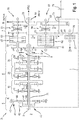
- Fig. 1 shows a schematic view of a transmission arrangement 3 according to a preferred embodiment of the invention.
- the gearbox assembly 3 is preferably used as a driving gear on an agricultural vehicle such as a tractor.
- drive power which is provided in particular by a drive motor 2, for example a diesel engine, can be transmitted with different ratios i to an output shaft 73 of the gearbox arrangement 3.
- a rear axle 74 drivingly connected to the output shaft 73, which converts rotation of the rear axle 74 (via wheels connected therewith) into a feed of the tractor, is therefore driven at different speeds depending on a ratio i selected in the gearbox assembly 3. Consequently, a tractor equipped with the manual transmission assembly 3 is movable in different speed ranges (drive levels) depending on the gear ratio i selected in the manual transmission assembly 3.
- the output shaft 73 of the gearbox assembly 3 is in the embodiment shown next to a spur gear with a front axle 78 of the tractor in drive connection brought.
- a gear z81 is arranged on the output shaft 73 of the transmission assembly 3, which meshes with a arranged on a hollow shaft 76 gear z91.
- the hollow shaft 77 is associated with an all-wheel clutch 77, which produces a drive connection between the hollow shaft 77 and the front axle 78 in the closed state.
- the shift gear assembly 3 shown either exclusively the rear axle 74 (four-wheel clutch 77 open) or leave Rear axle 74 and the front axle 78 drive together (four-wheel clutch 77 closed).
- the gearbox assembly 3 essentially comprises three functional groups which are in drive connection with each other via shafts.
- a power reverser 5 (reversing device) is arranged on the input side of the transmission assembly 3, ie directly driven by a drive motor 2, a power reverser 5 (reversing device) is arranged.
- This is connected via a hollow shaft 71 with a multi- speed transmission 6 in drive connection, which is switchable in seven power shift stages L 1..7 .
- the multi- speed transmission 6 is connected via a hollow shaft 72 with a dual-clutch transmission 7 in drive connection, which is switchable in four group switching stages G A..D .
- the dual-clutch transmission 7 has on the output side an output shaft 73, which is also the output shaft 73 of the transmission arrangement 3.
- a number of ratios i can be set with the gearbox arrangement 3 as a function of a power shift stage L 1..7 selected in the multistage transmission 6 and a group shift stage G A..D selected in the dual clutch transmission 7 between the transmission input (engine output shaft 8) and the output shaft 73. which initially correspond to one (forward) gear stage of the tractor. Furthermore, by means of the power reverser 5, a direction of rotation reversal can be achieved so that the direction of rotation of the output shaft 73 of the gearbox assembly 3 can be reversed. When the direction of rotation is reversed, a number of translations i with opposite direction can be set with the gearbox arrangement 3, which correspond respectively to reverse driving stages of the tractor.
- the power reverser 5 is designed in planetary construction and arranged coaxially with the input shaft of the gearbox assembly 3 (engine output shaft 8).
- the power reverser 5 has a driven by the engine output shaft 8 planet carrier 42, which supports an array of intermeshing planetary gears 44, 45.
- inner planet gears 45 roll off on a central sun gear 46, which is arranged on a hollow shaft 71.
- Outer planet gears 44 roll on an internally toothed Outer ring 43 from.
- the outer ring 43 is braked via a brake 41 from a freely rotatable state to a solid state.
- the planet carrier 42 can be brought into drive connection via a coupling 40 with the hollow shaft 71.
- the clutch 40 and the brake 41 can be operated coupled together to bring the power reverser 5 from a steady state to a reversed state - and vice versa. If the clutch 40 is closed and the brake 41 is opened, there is a direct drive connection between the engine output shaft 8 and the hollow shaft 71 coupled thereto so that the engine output shaft 8 and the hollow shaft 71 rotate in the same direction and at the same rotational speed (forward drive). If, on the other hand, the clutch 40 is opened and the brake 41 is closed, the reversing of the outer planet gears 44 on the braked outer ring 43 and the inner planetary gears 44 meshing with the outer planetary gears 45 reverses the direction of rotation of the sun gear 46 of the hollow shaft 71.
- the hollow shaft 71 rotates in the opposite direction to the motor output shaft 8.
- the rotational speed of the hollow shaft 71 may differ in magnitude from the rotational speed of the motor output shaft 8.
- the power reverser 5 has due to the described planetary construction on a relatively small axial length. This also has an overall advantageous effect on the axial length of the gearbox assembly 3.
- the multi-stage transmission 6 essentially comprises three planetary gear sets 10, 20, 30 which are drivingly connected together to form a three-stage transmission.
- the multistage transmission 6 is on the input side with the hollow shaft 71 in drive connection.
- the multistage transmission 6 is in drive connection with the hollow shaft 72.
- Each of the three planetary gear sets 10, 20, 30, whose structure is known per se need not be explained here, a clutch assembly is associated, each comprising a brake and a clutch.
- the first planetary gear 10 is assigned a brake 11 and a clutch 12.
- the brake 11 and the clutch 12 can be operated in the context of a switching operation coupled (switching operation), which can be a translation of the gear stage of the planetary gear set 10 between two states, a higher and thus lower compared ratio, change.
- a brake 21 and a clutch 22 are assigned to the second planetary gear set 20, and the third planetary gear set 30 is assigned a brake 31 and a clutch 32.
- the multi- speed transmission 6 of the embodiment can be switched to preferably seven powershift stages L 1..7 .
- the three clutch assemblies consisting of the pairings: brake 11 - clutch 12, brake 21 - clutch 22, and brake 31 - clutch 32 are selectively actuated.
- FIG. 2 shows the switching logic of the multi-speed transmission 6. Accordingly, with the multi-speed transmission 6 depending on the switching state of the three clutch assemblies - each formed from a pairing 11, 12; 21, 22; 31, 32 of brake and clutch - seven powershift stages L 1..7 switchable.
- the right-hand column of the table shows how many switching operations (related to a clutch arrangement) are respectively required to move from a power shift stage L n to a next higher power shift stage L n + 1 . The number of switching operations required is therefore a maximum of 2.
- the gearbox assembly 3 therefore has a gearbox 7, the double clutch construction is executed and that in four group switching stages G A..D different translation i A..D is switchable.
- group switching stages G n of the gearbox (dual-clutch transmission) 7 such translations i A..D between the output 73 of the gearbox assembly 3 and the multi-speed transmission 6 with the dual clutch transmission 7 connecting shaft 72 can be produced that for setting a next lower or next higher translation i the gearbox assembly 3 in the multi-stage transmission 6 at most two of the clutch assemblies 11, 12; 21, 22; 31, 32 are to be operated.
- the dual-clutch transmission 7 is assigned to the input side, the hollow shaft 72 and the output side, the output shaft 73 assigned.
- the dual-clutch transmission 7 essentially comprises a first partial transmission 50, to which a first transmission shaft 53 is assigned, and a second partial transmission 60, to which a second transmission shaft 63 spaced from the first transmission shaft 53 is assigned.
- Each of the transmission shafts 53, 63 can be brought into driving connection with the common output shaft 73, and each of the transmission shafts 53, 63 can be brought into drive connection with the hollow shaft 72 of the dual-clutch transmission 7 by closing a friction clutch 52, 62 associated with the respective partial transmission 50, 60.
- a gear z71 is arranged on the hollow shaft 72, which is also in meshing engagement with a gear z41 and a gear z51.
- the gears z41 and z51 are therefore driven by the gear z71 in the same direction of rotation. Due to different diameters, however, as indicated, the gear z41 rotates at a higher speed (i high ) than the gear z51 (i Low ).
- the gear z41 is arranged on a first drive shaft 51, which is arranged coaxially with the first gear shaft 53.
- a friction clutch 52 configured as a multi-plate clutch is shiftable between an open state in which the drive shaft 51 is drivingly disengaged from the first transmission shaft 53 and a closed state in which the drive shaft 51 is in driving connection with the first transmission shaft 53.
- the gear z51 is arranged on a second drive shaft 61, which is arranged coaxially with the second gear shaft 63.
- a designed as a multi-plate clutch friction clutch 62 is switchable between an open state in which the drive shaft 61 is drivingly released from the second transmission shaft 63, and a closed state in which the drive shaft 61 is in driving connection with the second transmission shaft 63.
- the friction clutch 62 of the second partial transmission 60 is designed to be stronger than the friction clutch 52 of the first partial transmission 50.
- the first and the second gear shaft 53, 63 are each assigned two gears z42, z43 and z52, z53. These mesh with one of the output shaft 73 associated gear z81, z82.
- the gears z42, z43 and z52, z53 are each loosely arranged on the transmission shafts 53, 63 and via adjusting means 54 and 64 (shift sleeves) to the respective transmission shaft 53, 63 detectable, so that depending on the switching state of the actuating means 54 and 64 between the output shaft 73 and the respective transmission shaft 53; 63 each a fixed speed ratio can be produced.
- the dual-clutch transmission 7 can be switched under load by during the opening of the friction clutch 52; 62 of a partial transmission 50; 60 each of the other partial transmission 60; 50 associated friction clutch 62; 52 is closed, so that one of the sub-transmission 50; 60 existing drive connection between the input shaft 72 and output shaft 73 through a respective other partial transmission 60; 50 to be produced drive connection can be replaced without interrupting a drive connection between input shaft 72 and output shaft 73.
- For pre-selection of a desired group shift stage G n is the relevant gear z42, z43; z52, z53 previously by adjusting means 54, 64 against rotation with the respective transmission shaft 53; 63 connected.
- the four group shift stages G A..D of the dual-clutch transmission 7 have four mutually different translations i A ... D and are with reference to the seven power shift stages L 1..7 of the multi-speed transmission 6 selected so that can be set with the gearbox assembly 3, a number of 20 different translations i.
- Fig. 3 shows in a tabular overview, in which way, ie by which combination of powershift stages L 1..7 and group switching stages G A..D, the 20 different translations i the gearbox assembly 3 can be generated.
- the name of the respective translation is specified for a first (left-hand) column (for example A-1 or C-3).
- the preceding letter is the name for the selected group shift stage and the following digit for the selected power shift stage. Accordingly, for example, a highest ratio i A-1 is produced by the choice of group shift stage A and power shift stage 1.
- the shift transmission assembly solves this problem in that the translations i A..D the dual clutch transmission 7 with respect to the powershift stages L 1..7 are tuned so that when changing the group shift G no longer between the two extreme power shift stages L 7 and L 1 is switched to achieve a next lower (or next higher) ratio i.
- Fig. 3 represented, for example, of the translation i A-7 in the translation i B-4 switched to achieve a next lower gear ratio of the gearbox assembly 3.
- the ratio i B-6 is switched to the ratio i C-1 , and is shifted from the ratio i C-3 to the ratio i D-1 , in order to achieve a next-lowest ratio i of the gearbox assembly 3.
- the gearbox assembly 3 is used in addition to the transmission of drive power to the output shaft 73 for the purpose of propulsion drive for the transmission of drive power for a PTO.
- the transmission assembly 3 a shaft bushing for a PTO (in Fig. 1 with “PTO” for "power-take-off” indicated).
- the shafts 71 and 72 are designed as hollow shafts and the planetary gear sets 10, 20, 30 made hollow to one of the engine output shaft 8 through the gearbox assembly 3 extending Shaft 70, which is used to drive a PTO 75 (in Fig. 1 not shown) serves to absorb. In this way, a direct and thus particularly energy-efficient drive power transmission from the drive motor 2 to a PTO output of the tractor is possible.
- the gearbox assembly 3 further provides an advantage in terms of adaptability to given environmental conditions.
- the dual-clutch transmission 7 as part of the gearbox assembly 3 allows a flexible center distance d between the shaft 70 and the output shaft 73, without the remaining functionality of the gearbox assembly 3 is impaired. For this purpose, first on the Fig. 4a and 4b directed.
- Fig. 4a a schematic cross-sectional view of the dual-clutch transmission 7 of the gearbox assembly 3 at a large center distance d l
- Fig. 4b a schematic cross-sectional view of the gearbox of the gearbox assembly 3 at a small center distance d s .
- the mutually coaxial shafts 70, 72 spaced on the one hand with an axial distance d 1 of the shafts 51, 53, and on the other hand with an axial distance d 4 of the shafts 61, 63, so that the gear z71 at the same time with the gear z41 and the gear z51 meshes.
- the shafts 51, 53 are spaced from the output shaft 73 with an axial distance d 2 .
- the shafts 61, 63 are spaced from the output shaft 73 by an axial distance d 3 .
- results with the center distances d 1 , d 2 , d 3 , d 4 a large center distance d l between shaft 70 (or 72) and output shaft 73rd
- Fig. 4b shows in contrast to the possibility of the shaft 70 (or 72) relative to the output shaft 73 to be arranged with a comparatively small axial distance d s , the center distances d 1 , d 2 , d 3 , d 4 remained unchanged between the four shaft centers are.
- Fig. 4b in comparison to Fig. 4a is to be taken from the smaller distance d s between shaft 70 (or 72) and output shaft 73 achieved in that according to Fig. 4b the shafts 51, 53 are spaced further apart from each other by the shafts 61, 63 than according to the embodiment of Figs Fig. 4a shown case.
- the gearbox assembly 3 can therefore be adapted advantageously to different installation conditions. This can be implemented constructively advantageous by a correspondingly designed transmission housing 4, which accommodates at least the dual-clutch transmission 7, advantageously the entire gearbox assembly 3.
- a correspondingly designed transmission housing 4 which accommodates at least the dual-clutch transmission 7, advantageously the entire gearbox assembly 3.
- the shaft 70 can be arranged with two different axial spacing dimensions d 1 , d s relative to the output shaft 73.
- FIG. 7 a simplified representation of a section of an agricultural vehicle 1 (eg tractor) with built-shift transmission assembly 3 in a schematic side view.
- the gearshift assembly 3 is a gearbox assembly 3 as previously described with reference to the preferred embodiment.
- the tractor 1 (indicated only by reference numeral) has a drive motor 2 (also indicated by reference numerals) and gear shift assembly 3.
- the gearbox assembly 3 is the same drivable by the drive motor 2 and is on the output side via the output shaft 73 with a rear axle 74 of the tractor 1 in drive connection, so that a drive power of the drive motor 2 in a driving movement (forward or backward, depending on the switching state of the power reverser 5) of the tractor 1 can be implemented ,
- the output shaft 73 is next via an all-wheel clutch 77 with a front axle 78 of the tractor in drive connection brought.
- the described gearshift arrangement has various advantages already explained.
- the number of required switching operations is reduced in a so-called group change by combining a switchable in seven powershift powershift transmission with a switchable in four group switching stages dual-clutch transmission. Due to the relatively small axial length of the planetary design executed power reverser, a relatively short overall length of the gearbox assembly can be achieved.
- the architecture in particular of the dual-clutch transmission further allows a variable center distance between a central transmission through shaft (PTO shaft) and the transmission output shaft.
Claims (17)
- Agencement de transmission (3) pour un véhicule agricole, en particulier pour un tracteur (1) comprenant une boîte de vitesses multi-étagée (6) qui est formée de trois trains planétaires (10, 20, 30) ainsi que d'agencements d'accouplement (11, 12 ; 21, 22 ; 31, 32) associés à ceux-ci et qui peut être commutée par un actionnement sélectif des agencements d'accouplement (11, 12 ; 21, 22 ; 31, 32) selon au moins sept rapports sous couple (L1..7), et une transmission (7), laquelle est en liaison d'entraînement avec la boîte de vitesses multi-étagée (6) et peut être commutée selon un nombre de rapports de groupe (Gn), de sorte qu'entre une sortie (73) et une entrée (8) de l'agencement de transmission (3) un nombre de rapports de transmission (i) soit instauré en fonction d'un rapport sous couple sélectionné (L1..7) et d'un rapport de groupe (Gn), chaque agencement d'accouplement (11, 12 ; 21, 22 ; 31, 32) étant formé respectivement d'un appariement d'un accouplement (12, 22, 32) et d'un frein (11, 21, 31), et les rapports de groupe (Gn) de la transmission (7) permettant d'instaurer des rapports de multiplication (iA..D) entre la sortie (73) de l'agencement de transmission (3) et un arbre (72) reliant les transmissions (6, 7), de façon que, pour instaurer un rapport de multiplication immédiatement inférieur ou immédiatement supérieur (i) de l'agencement de transmission (3) dans la boîte de vitesses multi-étagée (6), au maximum deux des agencements d'accouplement (11, 12 ; 21, 22 ; 31, 32) doivent être actionnés.
- Agencement de transmission selon la revendication 1, caractérisé en ce que la transmission est constituée par une transmission à double embrayage (7) qui peut être commutée selon, en particulier, quatre rapports de groupe (GA..D) de rapport de multiplication (iA..D) différent.
- Agencement de transmission selon la revendication 2, caractérisé en ce que la transmission à double embrayage (7) comporte une première transmission partielle (50), à laquelle est associé un premier arbre de transmission (53), et une seconde transmission partielle (60) à laquelle est associé un second arbre de transmission (63) distant du premier arbre de transmission (53), chacun des arbres de transmission (53, 63) pouvant être amené en liaison d'entraînement avec un arbre mené commun (73), et chacun des arbres de transmission (53 ; 63) pouvant être amené en liaison d'entraînement avec un arbre d'entrée (72) de la transmission à double embrayage (7) par la fermeture d'un embrayage à friction (52 ; 62) associé à la transmission partielle correspondante (50 ; 60).
- Agencement de transmission selon la revendication 3, caractérisé en ce que le premier arbre de transmission (53) peut être couplé à un premier arbre menant (51) au moyen de l'embrayage à friction (52) associé à la première transmission partielle (50), et le second arbre de transmission (63) peut être couplé à un second arbre menant (61) au moyen de l'embrayage à friction (62) associé à la seconde transmission partielle (60), le premier et le second arbre d'entraînement (51, 61) faisant partie d'une transmission intermédiaire (9) entraînable par l'arbre d'entrée (72).
- Agencement de transmission selon la revendication 4, caractérisé en ce que la transmission intermédiaire (9) est constituée par un engrenage à roues droites qui place un premier arbre (51) et un second arbre (61) parallèle à celui-ci dans un rapport de vitesse de rotation fixe qui est préférentiellement différent de 1, pour un sens de rotation en particulier identique des arbres (51, 61).
- Agencement de transmission selon une des revendications 3 à 5, caractérisé en ce qu'au premier et au second arbre de transmission (53 ; 63) sont associées respectivement en particulier deux roues dentées (z42, z43 ; z52, z53) qui s'engrènent chacune avec une roue dentée (z81, z82) associée à l'arbre mené (73), de façon à instaurer au moins un rapport de vitesse de rotation fixe entre l'arbre mené (73) et l'arbre de transmission respectif (53 ; 63).
- Agencement de transmission selon une des revendications 3 à 6, caractérisé en ce que l'arbre d'entrée (72) de la transmission à double embrayage (7) peut être amené en liaison d'entraînement avec l'arbre mené commun (73) par l'intermédiaire de chacune des deux transmissions partielles (50, 60) à travers respectivement deux rapports de groupe commutables (GB, D ; GA, C), de sorte que la transmission à double embrayage (7) est commutable selon au total quatre rapports de groupe (GA, B, C, D).
- Agencement de transmission selon une des revendications 3 à 7, caractérisé en ce que la transmission à double embrayage (7) peut être commutée sous charge par le fait que, pendant l'ouverture de l'embrayage à friction (52 ; 62) d'une transmission partielle (50 ; 60), l'embrayage à friction (62 ; 52) associé respectivement à l'autre transmission partielle (60 ; 50) est fermé, de sorte qu'une liaison d'entraînement établie par l'intermédiaire d'une des transmissions partielles (50 ; 60) entre arbre d'entrée (72) et arbre mené (73) est remplaçable par une liaison d'entraînement à établir par l'intermédiaire de l'autre transmission partielle respective (60 ; 50), sans interrompre une liaison d'entraînement entre arbre d'entrée (72) et arbre mené (73) .
- Agencement de transmission selon une des revendications 6 à 8, caractérisé en ce que pour la présélection d'un rapport de groupe (Gn), la roue dentée correspondante (z42, z43 ; z52, z53) peut être solidarisée en rotation avec l'arbre de transmission respectif (53 ; 63) par l'intermédiaire de moyens actionneurs (54, 64).
- Agencement de transmission selon une des revendications précédentes, caractérisé en ce que l'agencement de transmission (3) est pourvu d'un passage d'arbre pour une commande de prise de force (75) du véhicule agricole (1) par le fait qu'un arbre d'entrée (71) de la boîte de vitesses multi-étagée (6) et un arbre d'entrée (72) de la transmission (7) sont conformés en arbres creux et reçoivent intérieurement un arbre (70) pour entraîner une transmission de prise de force (75).
- Agencement de transmission selon une des revendications précédentes, caractérisé par un carter de transmission (4) qui reçoit au moins la transmission (7) et dans lequel l'arbre (70) pour l'entraînement de la transmission de prise de force (75), lequel est en particulier disposé coaxialement à l'arbre d'entrée (72) de la transmission (7), peut être disposé avec au moins deux dimensions d'entraxe différentes (dI, dS) par rapport à l'arbre mené (73), un entraxe (d1, d4) de chacun des arbres de transmission (53, 63) demeurant inchangé par rapport à l'arbre (70, 72) et un entraxe (d2, d3) de chacun des arbres de transmission (53, 63) demeurant inchangé par rapport à l'arbre mené (73).
- Agencement de transmission selon une des revendications précédentes, caractérisé en ce qu'à l'agencement de transmission (3) est associé un dispositif d'inversion (5) qui peut être actionné par l'intermédiaire d'un agencement d'accouplement (40, 41) et qui permet d'inverser un sens de rotation au moins de la partie menée (73) de l'agencement de transmission (3).
- Agencement de transmission selon la revendication 12, caractérisé en ce que le dispositif d'inversion (5) est réalisé en conception planétaire et est disposé coaxialement à un arbre d'entrée (8) de l'agencement de transmission (3), en particulier côté entrée de la boîte de vitesses multi-étagée (6).
- Agencement de transmission selon une des revendications précédentes, caractérisé en ce qu'en cas de commutation vers le rapport de multiplication immédiatement inférieur, respectivement immédiatement supérieur (i) de l'agencement de transmission (3), laquelle exige un passage entre le premier rapport de groupe (GA) et le second rapport de groupe (GB) et/ou un passage entre le troisième rapport de groupe (GC) et le quatrième rapport de groupe (GD), un seul des agencements d'accouplement (11, 12 ; 21, 22 ; 31, 32) peut être actionné dans la boîte de vitesses multi-étagée (6).
- Agencement de transmission selon une des revendications précédentes, caractérisé en ce que seulement en cas de commutation vers un rapport de démultiplication immédiatement inférieur, respectivement immédiatement supérieur (i) de l'agencement de transmission (3), lequel exige un passage entre le second rapport de groupe (GB) et le troisième rapport de groupe (GC), deux des agencements d'accouplement (11, 12 ; 21, 22 ; 31, 32) peuvent être actionnés dans la boîte de vitesses multi-étagée (6).
- Agencement de transmission selon une des revendications précédentes, caractérisé en ce que les rapports sous couple (L1..7) de la boîte de vitesses multi-étagée et les rapports de groupe (Gn) de la transmission (7) sont harmonisés de façon qu'en cas de commutation vers un rapport de multiplication immédiatement inférieur, respectivement immédiatement supérieur (i) de l'agencement de transmission (3), une vitesse de rotation au niveau de la partie menée (73) de l'agencement de transmission (3) augmente, respectivement diminue selon un facteur sensiblement constant.
- Véhicule agricole, en particulier tracteur (1), comprenant un moteur d'entraînement (2) et un agencement de transmission (3) selon une des revendications précédentes, l'agencement de transmission (3) pouvant être entraîné par le moteur d'entraînement (2) et étant en liaison d'entraînement avec au moins un essieu (74) du véhicule (1) et/ou pouvant être amené en liaison d'entraînement avec un essieu (78).
Applications Claiming Priority (1)
| Application Number | Priority Date | Filing Date | Title |
|---|---|---|---|
| DE102013110709.5A DE102013110709A1 (de) | 2013-09-27 | 2013-09-27 | Schaltgetriebeanordnung |
Publications (2)
| Publication Number | Publication Date |
|---|---|
| EP2916044A1 EP2916044A1 (fr) | 2015-09-09 |
| EP2916044B1 true EP2916044B1 (fr) | 2019-06-05 |
Family
ID=51176167
Family Applications (1)
| Application Number | Title | Priority Date | Filing Date |
|---|---|---|---|
| EP14176295.5A Active EP2916044B1 (fr) | 2013-09-27 | 2014-07-09 | Système d'engrenage |
Country Status (4)
| Country | Link |
|---|---|
| EP (1) | EP2916044B1 (fr) |
| BR (1) | BR102014021616B1 (fr) |
| DE (1) | DE102013110709A1 (fr) |
| RU (1) | RU2653410C2 (fr) |
Cited By (1)
| Publication number | Priority date | Publication date | Assignee | Title |
|---|---|---|---|---|
| CN107407385A (zh) * | 2015-04-07 | 2017-11-28 | 迪尔公司 | 用于农业作业车辆的传动系统 |
Families Citing this family (15)
| Publication number | Priority date | Publication date | Assignee | Title |
|---|---|---|---|---|
| DE102015206877A1 (de) | 2015-04-16 | 2016-10-20 | Zf Friedrichshafen Ag | Splittergetriebe, Gesamtgetriebe und landwirtschaftliche Arbeitsmaschine |
| DE102015206881A1 (de) * | 2015-04-16 | 2016-10-20 | Zf Friedrichshafen Ag | Volllastschaltbare Getriebeanordnung und landwirtschaftliche Arbeitsmaschine |
| FR3042248B1 (fr) * | 2015-10-08 | 2017-12-15 | Groupement International De Mec Agricole | Ensemble de boite de vitesses pour vehicule agricole a large gamme de vitesses |
| RU2717283C2 (ru) * | 2016-05-17 | 2020-03-19 | Федеральное государственное бюджетное образовательное учреждение высшего профессионального образования "Курганский государственный университет" | Двухпланетарная коробка передач 29R20 |
| CN109843623A (zh) * | 2016-08-08 | 2019-06-04 | 舍弗勒工程有限公司 | 用于机动车的动力总成系统以及操作动力总成系统的方法 |
| DE102016223569A1 (de) * | 2016-11-28 | 2018-05-30 | Zf Friedrichshafen Ag | Verfahren zum Betrieb einer automatisierten Getriebesteuerung |
| DE102017007763B4 (de) * | 2017-08-16 | 2020-03-19 | Daimler Ag | Gruppengetriebevorrichtung |
| DE102019206979A1 (de) * | 2019-05-14 | 2020-11-19 | Deere & Company | Lastschaltgetriebe für Landmaschinen |
| DE102019216303A1 (de) * | 2019-10-23 | 2021-04-29 | Deere & Company | Getriebe |
| BR112022024604A2 (pt) | 2020-09-01 | 2023-03-28 | Deere & Co | Unidade de transmissão, conjunto de transmissão e trator agrícola |
| DE102020122827A1 (de) | 2020-09-01 | 2022-03-03 | Deere & Company | Getriebeeinheit, Getriebeanordnung und landwirtschaftliches Zugfahrzeug |
| EP4249766A3 (fr) | 2020-09-01 | 2023-11-08 | Deere & Company | Unité de transmission, ensemble de transmission et véhicule de traction agricole |
| EP4105520A1 (fr) | 2021-06-16 | 2022-12-21 | Deere & Company | Transmission et véhicule utilitaire agricole ou industriel |
| DE102021212363B3 (de) | 2021-11-03 | 2022-10-20 | Zf Friedrichshafen Ag | Lastschaltgetriebe eines Kraftfahrzeugs |
| DE102022207638B4 (de) | 2022-07-11 | 2024-02-15 | Zf Friedrichshafen Ag | Kraftfahrzeuggetriebe |
Family Cites Families (8)
| Publication number | Priority date | Publication date | Assignee | Title |
|---|---|---|---|---|
| GB2069635B (en) * | 1980-02-18 | 1984-02-01 | Automotive Prod Co Ltd | Rotary transmission |
| DE3217993A1 (de) * | 1982-05-13 | 1983-11-17 | Deere & Co., 61265 Moline, Ill. | Getriebe, insbesondere fuer land- oder baufahrzeuge |
| SU1204413A1 (ru) * | 1984-07-31 | 1986-01-15 | Институт проблем надежности и долговечности машин АН БССР | Коробка передач |
| DE19910299C1 (de) * | 1999-03-10 | 2001-04-19 | Daimler Chrysler Ag | Planetenräder-Wechselgetriebe mit drei Teilgetrieben |
| RU2290552C1 (ru) * | 2005-08-17 | 2006-12-27 | Общество с ограниченной ответственностью "КАТЕ" | Коробка передач |
| RU2010107928A (ru) * | 2010-03-03 | 2011-09-10 | Джи Эм Глоубал Текнолоджи Оперейшнз, Инк. (Us) | Многоступенчатая планетарная трансмиссия с тремя тормозами и четырьмя муфтами (варианты) |
| DE102010039984A1 (de) * | 2010-08-31 | 2012-03-01 | Zf Friedrichshafen Ag | Mehrstufengetriebe |
| DE102011081764A1 (de) * | 2011-08-30 | 2013-02-28 | Zf Friedrichshafen Ag | Antriebsanordnung einer mobilen Arbeitsmaschine |
-
2013
- 2013-09-27 DE DE102013110709.5A patent/DE102013110709A1/de not_active Withdrawn
-
2014
- 2014-07-09 EP EP14176295.5A patent/EP2916044B1/fr active Active
- 2014-09-01 BR BR102014021616-2A patent/BR102014021616B1/pt active IP Right Grant
- 2014-09-24 RU RU2014138593A patent/RU2653410C2/ru active
Non-Patent Citations (1)
| Title |
|---|
| None * |
Cited By (1)
| Publication number | Priority date | Publication date | Assignee | Title |
|---|---|---|---|---|
| CN107407385A (zh) * | 2015-04-07 | 2017-11-28 | 迪尔公司 | 用于农业作业车辆的传动系统 |
Also Published As
| Publication number | Publication date |
|---|---|
| DE102013110709A1 (de) | 2015-04-02 |
| EP2916044A1 (fr) | 2015-09-09 |
| RU2014138593A (ru) | 2016-04-10 |
| RU2653410C2 (ru) | 2018-05-08 |
| BR102014021616A2 (pt) | 2015-09-15 |
| BR102014021616B1 (pt) | 2022-03-29 |
Similar Documents
| Publication | Publication Date | Title |
|---|---|---|
| EP2916044B1 (fr) | Système d'engrenage | |
| EP2899427B1 (fr) | Boîte de vitesses d'un véhicule automobile | |
| DE102014215156B4 (de) | Gruppengetriebe eines Kraftfahrzeugs | |
| EP2914874B1 (fr) | Transmission à double embrayage | |
| EP2914875B1 (fr) | Transmission à double embrayage | |
| DE102011011376B4 (de) | Mehrgang-Planetengetriebe mit bis zu zehn Vorwärtsgängen | |
| EP2738420B1 (fr) | Boîte de vitesses à double embrayage pour un véhicule automobile | |
| EP3171053B1 (fr) | Boîte de vitesses | |
| WO1987003661A1 (fr) | Boite de changement a echelonnement multiple de vitesses | |
| EP2469125A1 (fr) | Boîte de vitesses automatique, notamment automatisée, pour un véhicule automobile | |
| EP0397804B1 (fr) | Boite de vitesses couplable sous charge a rapport variable en continu | |
| DE102013220919B4 (de) | Verfahren zur Steuerung eines stufenloses Getriebes | |
| DE102012208161B4 (de) | Getriebe, insbesondere automatisiertes Schaltgetriebe, sowie Verwendung einer Viergang-Schaltgruppe und Kraftfahrzeug | |
| DE112011105576T5 (de) | Mehrkupplungsgetriebe für ein Kraftfahrzeug | |
| DE102020201690B3 (de) | Leistungsverzweigtes stufenloses Getriebe | |
| DE102020201778B4 (de) | Leistungsverzweigtes stufenloses Getriebe | |
| DE69730726T2 (de) | Rückwärtsgang-schaltmechanismus in einem querliegenden vorderradgetriebe | |
| DE102012221238A1 (de) | Getriebe | |
| EP3338007A1 (fr) | Boîte de vitesses à groupes et système d'engrenage avec boîte de vitesses à groupes | |
| EP2864661B1 (fr) | Unité comprenant une boîte de vitesses et des embrayages et procédé de contrôle pour un agencement de transmission la comprenant | |
| DE102019207925A1 (de) | Nebenabtriebsgetriebe und landwirtschaftliche Arbeitsmaschine | |
| DE102015204600B4 (de) | Getriebe für ein Kraftfahrzeug und Verfahren zum Betreiben eines solchen | |
| DE102020201775B3 (de) | Leistungsverzweigtes stufenloses Getriebe | |
| DE102021211734B3 (de) | Drei- oder Vierganggetriebe für einen elektrischen Antrieb | |
| DE102020202003B3 (de) | Leistungsverzweigtes stufenloses Getriebe |
Legal Events
| Date | Code | Title | Description |
|---|---|---|---|
| PUAI | Public reference made under article 153(3) epc to a published international application that has entered the european phase |
Free format text: ORIGINAL CODE: 0009012 |
|
| AK | Designated contracting states |
Kind code of ref document: A1 Designated state(s): AL AT BE BG CH CY CZ DE DK EE ES FI FR GB GR HR HU IE IS IT LI LT LU LV MC MK MT NL NO PL PT RO RS SE SI SK SM TR |
|
| AX | Request for extension of the european patent |
Extension state: BA ME |
|
| 17P | Request for examination filed |
Effective date: 20160309 |
|
| RBV | Designated contracting states (corrected) |
Designated state(s): AL AT BE BG CH CY CZ DE DK EE ES FI FR GB GR HR HU IE IS IT LI LT LU LV MC MK MT NL NO PL PT RO RS SE SI SK SM TR |
|
| RIC1 | Information provided on ipc code assigned before grant |
Ipc: F16H 37/04 20060101AFI20181205BHEP Ipc: F16H 3/00 20060101ALN20181205BHEP Ipc: F16H 3/66 20060101ALN20181205BHEP |
|
| GRAP | Despatch of communication of intention to grant a patent |
Free format text: ORIGINAL CODE: EPIDOSNIGR1 |
|
| STAA | Information on the status of an ep patent application or granted ep patent |
Free format text: STATUS: GRANT OF PATENT IS INTENDED |
|
| INTG | Intention to grant announced |
Effective date: 20190208 |
|
| GRAS | Grant fee paid |
Free format text: ORIGINAL CODE: EPIDOSNIGR3 |
|
| GRAA | (expected) grant |
Free format text: ORIGINAL CODE: 0009210 |
|
| STAA | Information on the status of an ep patent application or granted ep patent |
Free format text: STATUS: THE PATENT HAS BEEN GRANTED |
|
| AK | Designated contracting states |
Kind code of ref document: B1 Designated state(s): AL AT BE BG CH CY CZ DE DK EE ES FI FR GB GR HR HU IE IS IT LI LT LU LV MC MK MT NL NO PL PT RO RS SE SI SK SM TR |
|
| REG | Reference to a national code |
Ref country code: GB Ref legal event code: FG4D Free format text: NOT ENGLISH |
|
| REG | Reference to a national code |
Ref country code: CH Ref legal event code: EP |
|
| REG | Reference to a national code |
Ref country code: AT Ref legal event code: REF Ref document number: 1140320 Country of ref document: AT Kind code of ref document: T Effective date: 20190615 |
|
| REG | Reference to a national code |
Ref country code: IE Ref legal event code: FG4D Free format text: LANGUAGE OF EP DOCUMENT: GERMAN |
|
| REG | Reference to a national code |
Ref country code: DE Ref legal event code: R096 Ref document number: 502014011837 Country of ref document: DE |
|
| REG | Reference to a national code |
Ref country code: NL Ref legal event code: MP Effective date: 20190605 |
|
| REG | Reference to a national code |
Ref country code: LT Ref legal event code: MG4D |
|
| PG25 | Lapsed in a contracting state [announced via postgrant information from national office to epo] |
Ref country code: FI Free format text: LAPSE BECAUSE OF FAILURE TO SUBMIT A TRANSLATION OF THE DESCRIPTION OR TO PAY THE FEE WITHIN THE PRESCRIBED TIME-LIMIT Effective date: 20190605 Ref country code: NO Free format text: LAPSE BECAUSE OF FAILURE TO SUBMIT A TRANSLATION OF THE DESCRIPTION OR TO PAY THE FEE WITHIN THE PRESCRIBED TIME-LIMIT Effective date: 20190905 Ref country code: AL Free format text: LAPSE BECAUSE OF FAILURE TO SUBMIT A TRANSLATION OF THE DESCRIPTION OR TO PAY THE FEE WITHIN THE PRESCRIBED TIME-LIMIT Effective date: 20190605 Ref country code: SE Free format text: LAPSE BECAUSE OF FAILURE TO SUBMIT A TRANSLATION OF THE DESCRIPTION OR TO PAY THE FEE WITHIN THE PRESCRIBED TIME-LIMIT Effective date: 20190605 Ref country code: HR Free format text: LAPSE BECAUSE OF FAILURE TO SUBMIT A TRANSLATION OF THE DESCRIPTION OR TO PAY THE FEE WITHIN THE PRESCRIBED TIME-LIMIT Effective date: 20190605 Ref country code: LT Free format text: LAPSE BECAUSE OF FAILURE TO SUBMIT A TRANSLATION OF THE DESCRIPTION OR TO PAY THE FEE WITHIN THE PRESCRIBED TIME-LIMIT Effective date: 20190605 Ref country code: ES Free format text: LAPSE BECAUSE OF FAILURE TO SUBMIT A TRANSLATION OF THE DESCRIPTION OR TO PAY THE FEE WITHIN THE PRESCRIBED TIME-LIMIT Effective date: 20190605 |
|
| PG25 | Lapsed in a contracting state [announced via postgrant information from national office to epo] |
Ref country code: RS Free format text: LAPSE BECAUSE OF FAILURE TO SUBMIT A TRANSLATION OF THE DESCRIPTION OR TO PAY THE FEE WITHIN THE PRESCRIBED TIME-LIMIT Effective date: 20190605 Ref country code: BG Free format text: LAPSE BECAUSE OF FAILURE TO SUBMIT A TRANSLATION OF THE DESCRIPTION OR TO PAY THE FEE WITHIN THE PRESCRIBED TIME-LIMIT Effective date: 20190905 Ref country code: GR Free format text: LAPSE BECAUSE OF FAILURE TO SUBMIT A TRANSLATION OF THE DESCRIPTION OR TO PAY THE FEE WITHIN THE PRESCRIBED TIME-LIMIT Effective date: 20190906 Ref country code: LV Free format text: LAPSE BECAUSE OF FAILURE TO SUBMIT A TRANSLATION OF THE DESCRIPTION OR TO PAY THE FEE WITHIN THE PRESCRIBED TIME-LIMIT Effective date: 20190605 |
|
| PG25 | Lapsed in a contracting state [announced via postgrant information from national office to epo] |
Ref country code: CZ Free format text: LAPSE BECAUSE OF FAILURE TO SUBMIT A TRANSLATION OF THE DESCRIPTION OR TO PAY THE FEE WITHIN THE PRESCRIBED TIME-LIMIT Effective date: 20190605 Ref country code: RO Free format text: LAPSE BECAUSE OF FAILURE TO SUBMIT A TRANSLATION OF THE DESCRIPTION OR TO PAY THE FEE WITHIN THE PRESCRIBED TIME-LIMIT Effective date: 20190605 Ref country code: SK Free format text: LAPSE BECAUSE OF FAILURE TO SUBMIT A TRANSLATION OF THE DESCRIPTION OR TO PAY THE FEE WITHIN THE PRESCRIBED TIME-LIMIT Effective date: 20190605 Ref country code: NL Free format text: LAPSE BECAUSE OF FAILURE TO SUBMIT A TRANSLATION OF THE DESCRIPTION OR TO PAY THE FEE WITHIN THE PRESCRIBED TIME-LIMIT Effective date: 20190605 Ref country code: EE Free format text: LAPSE BECAUSE OF FAILURE TO SUBMIT A TRANSLATION OF THE DESCRIPTION OR TO PAY THE FEE WITHIN THE PRESCRIBED TIME-LIMIT Effective date: 20190605 Ref country code: PT Free format text: LAPSE BECAUSE OF FAILURE TO SUBMIT A TRANSLATION OF THE DESCRIPTION OR TO PAY THE FEE WITHIN THE PRESCRIBED TIME-LIMIT Effective date: 20191007 |
|
| PG25 | Lapsed in a contracting state [announced via postgrant information from national office to epo] |
Ref country code: IT Free format text: LAPSE BECAUSE OF FAILURE TO SUBMIT A TRANSLATION OF THE DESCRIPTION OR TO PAY THE FEE WITHIN THE PRESCRIBED TIME-LIMIT Effective date: 20190605 Ref country code: SM Free format text: LAPSE BECAUSE OF FAILURE TO SUBMIT A TRANSLATION OF THE DESCRIPTION OR TO PAY THE FEE WITHIN THE PRESCRIBED TIME-LIMIT Effective date: 20190605 Ref country code: IS Free format text: LAPSE BECAUSE OF FAILURE TO SUBMIT A TRANSLATION OF THE DESCRIPTION OR TO PAY THE FEE WITHIN THE PRESCRIBED TIME-LIMIT Effective date: 20191005 |
|
| REG | Reference to a national code |
Ref country code: CH Ref legal event code: PL |
|
| REG | Reference to a national code |
Ref country code: DE Ref legal event code: R097 Ref document number: 502014011837 Country of ref document: DE |
|
| PG25 | Lapsed in a contracting state [announced via postgrant information from national office to epo] |
Ref country code: TR Free format text: LAPSE BECAUSE OF FAILURE TO SUBMIT A TRANSLATION OF THE DESCRIPTION OR TO PAY THE FEE WITHIN THE PRESCRIBED TIME-LIMIT Effective date: 20190605 Ref country code: MC Free format text: LAPSE BECAUSE OF FAILURE TO SUBMIT A TRANSLATION OF THE DESCRIPTION OR TO PAY THE FEE WITHIN THE PRESCRIBED TIME-LIMIT Effective date: 20190605 |
|
| PLBE | No opposition filed within time limit |
Free format text: ORIGINAL CODE: 0009261 |
|
| STAA | Information on the status of an ep patent application or granted ep patent |
Free format text: STATUS: NO OPPOSITION FILED WITHIN TIME LIMIT |
|
| PG25 | Lapsed in a contracting state [announced via postgrant information from national office to epo] |
Ref country code: PL Free format text: LAPSE BECAUSE OF FAILURE TO SUBMIT A TRANSLATION OF THE DESCRIPTION OR TO PAY THE FEE WITHIN THE PRESCRIBED TIME-LIMIT Effective date: 20190605 Ref country code: DK Free format text: LAPSE BECAUSE OF FAILURE TO SUBMIT A TRANSLATION OF THE DESCRIPTION OR TO PAY THE FEE WITHIN THE PRESCRIBED TIME-LIMIT Effective date: 20190605 |
|
| 26N | No opposition filed |
Effective date: 20200306 |
|
| PG25 | Lapsed in a contracting state [announced via postgrant information from national office to epo] |
Ref country code: LU Free format text: LAPSE BECAUSE OF NON-PAYMENT OF DUE FEES Effective date: 20190709 Ref country code: SI Free format text: LAPSE BECAUSE OF FAILURE TO SUBMIT A TRANSLATION OF THE DESCRIPTION OR TO PAY THE FEE WITHIN THE PRESCRIBED TIME-LIMIT Effective date: 20190605 Ref country code: CH Free format text: LAPSE BECAUSE OF NON-PAYMENT OF DUE FEES Effective date: 20190731 Ref country code: LI Free format text: LAPSE BECAUSE OF NON-PAYMENT OF DUE FEES Effective date: 20190731 |
|
| PG25 | Lapsed in a contracting state [announced via postgrant information from national office to epo] |
Ref country code: IE Free format text: LAPSE BECAUSE OF NON-PAYMENT OF DUE FEES Effective date: 20190709 |
|
| GBPC | Gb: european patent ceased through non-payment of renewal fee |
Effective date: 20190905 |
|
| REG | Reference to a national code |
Ref country code: AT Ref legal event code: MM01 Ref document number: 1140320 Country of ref document: AT Kind code of ref document: T Effective date: 20190709 |
|
| PG25 | Lapsed in a contracting state [announced via postgrant information from national office to epo] |
Ref country code: GB Free format text: LAPSE BECAUSE OF NON-PAYMENT OF DUE FEES Effective date: 20190905 |
|
| PG25 | Lapsed in a contracting state [announced via postgrant information from national office to epo] |
Ref country code: AT Free format text: LAPSE BECAUSE OF NON-PAYMENT OF DUE FEES Effective date: 20190709 |
|
| PG25 | Lapsed in a contracting state [announced via postgrant information from national office to epo] |
Ref country code: CY Free format text: LAPSE BECAUSE OF FAILURE TO SUBMIT A TRANSLATION OF THE DESCRIPTION OR TO PAY THE FEE WITHIN THE PRESCRIBED TIME-LIMIT Effective date: 20190605 |
|
| PG25 | Lapsed in a contracting state [announced via postgrant information from national office to epo] |
Ref country code: MT Free format text: LAPSE BECAUSE OF FAILURE TO SUBMIT A TRANSLATION OF THE DESCRIPTION OR TO PAY THE FEE WITHIN THE PRESCRIBED TIME-LIMIT Effective date: 20190605 Ref country code: HU Free format text: LAPSE BECAUSE OF FAILURE TO SUBMIT A TRANSLATION OF THE DESCRIPTION OR TO PAY THE FEE WITHIN THE PRESCRIBED TIME-LIMIT; INVALID AB INITIO Effective date: 20140709 |
|
| PG25 | Lapsed in a contracting state [announced via postgrant information from national office to epo] |
Ref country code: MK Free format text: LAPSE BECAUSE OF FAILURE TO SUBMIT A TRANSLATION OF THE DESCRIPTION OR TO PAY THE FEE WITHIN THE PRESCRIBED TIME-LIMIT Effective date: 20190605 |
|
| P01 | Opt-out of the competence of the unified patent court (upc) registered |
Effective date: 20230515 |
|
| PGFP | Annual fee paid to national office [announced via postgrant information from national office to epo] |
Ref country code: FR Payment date: 20230726 Year of fee payment: 10 Ref country code: DE Payment date: 20230719 Year of fee payment: 10 Ref country code: BE Payment date: 20230719 Year of fee payment: 10 |