EP2915779A1 - Integrated carbon dioxide conversion system for connecting oxy-fuel combustion and catalytic conversion process - Google Patents
Integrated carbon dioxide conversion system for connecting oxy-fuel combustion and catalytic conversion process Download PDFInfo
- Publication number
- EP2915779A1 EP2915779A1 EP13850853.6A EP13850853A EP2915779A1 EP 2915779 A1 EP2915779 A1 EP 2915779A1 EP 13850853 A EP13850853 A EP 13850853A EP 2915779 A1 EP2915779 A1 EP 2915779A1
- Authority
- EP
- European Patent Office
- Prior art keywords
- oxy
- carbon dioxide
- oxygen
- conversion system
- fuel combustor
- Prior art date
- Legal status (The legal status is an assumption and is not a legal conclusion. Google has not performed a legal analysis and makes no representation as to the accuracy of the status listed.)
- Granted
Links
Images





Classifications
-
- F—MECHANICAL ENGINEERING; LIGHTING; HEATING; WEAPONS; BLASTING
- F23—COMBUSTION APPARATUS; COMBUSTION PROCESSES
- F23C—METHODS OR APPARATUS FOR COMBUSTION USING FLUID FUEL OR SOLID FUEL SUSPENDED IN A CARRIER GAS OR AIR
- F23C7/00—Combustion apparatus characterised by arrangements for air supply
-
- B—PERFORMING OPERATIONS; TRANSPORTING
- B01—PHYSICAL OR CHEMICAL PROCESSES OR APPARATUS IN GENERAL
- B01D—SEPARATION
- B01D53/00—Separation of gases or vapours; Recovering vapours of volatile solvents from gases; Chemical or biological purification of waste gases, e.g. engine exhaust gases, smoke, fumes, flue gases, aerosols
- B01D53/34—Chemical or biological purification of waste gases
- B01D53/46—Removing components of defined structure
- B01D53/62—Carbon oxides
-
- B—PERFORMING OPERATIONS; TRANSPORTING
- B01—PHYSICAL OR CHEMICAL PROCESSES OR APPARATUS IN GENERAL
- B01J—CHEMICAL OR PHYSICAL PROCESSES, e.g. CATALYSIS OR COLLOID CHEMISTRY; THEIR RELEVANT APPARATUS
- B01J12/00—Chemical processes in general for reacting gaseous media with gaseous media; Apparatus specially adapted therefor
- B01J12/007—Chemical processes in general for reacting gaseous media with gaseous media; Apparatus specially adapted therefor in the presence of catalytically active bodies, e.g. porous plates
-
- B—PERFORMING OPERATIONS; TRANSPORTING
- B01—PHYSICAL OR CHEMICAL PROCESSES OR APPARATUS IN GENERAL
- B01J—CHEMICAL OR PHYSICAL PROCESSES, e.g. CATALYSIS OR COLLOID CHEMISTRY; THEIR RELEVANT APPARATUS
- B01J19/00—Chemical, physical or physico-chemical processes in general; Their relevant apparatus
- B01J19/24—Stationary reactors without moving elements inside
- B01J19/2475—Membrane reactors
-
- C—CHEMISTRY; METALLURGY
- C01—INORGANIC CHEMISTRY
- C01B—NON-METALLIC ELEMENTS; COMPOUNDS THEREOF; METALLOIDS OR COMPOUNDS THEREOF NOT COVERED BY SUBCLASS C01C
- C01B13/00—Oxygen; Ozone; Oxides or hydroxides in general
- C01B13/02—Preparation of oxygen
- C01B13/0229—Purification or separation processes
- C01B13/0248—Physical processing only
- C01B13/0251—Physical processing only by making use of membranes
-
- C—CHEMISTRY; METALLURGY
- C01—INORGANIC CHEMISTRY
- C01B—NON-METALLIC ELEMENTS; COMPOUNDS THEREOF; METALLOIDS OR COMPOUNDS THEREOF NOT COVERED BY SUBCLASS C01C
- C01B3/00—Hydrogen; Gaseous mixtures containing hydrogen; Separation of hydrogen from mixtures containing it; Purification of hydrogen; Reversible storage of hydrogen
- C01B3/02—Production of hydrogen; Production of gaseous mixtures containing hydrogen
- C01B3/32—Production of hydrogen; Production of gaseous mixtures containing hydrogen by reaction of gaseous or liquid organic compounds with gasifying agents, e.g. water, carbon dioxide or air
- C01B3/34—Production of hydrogen; Production of gaseous mixtures containing hydrogen by reaction of gaseous or liquid organic compounds with gasifying agents, e.g. water, carbon dioxide or air by reaction of hydrocarbons with gasifying agents
- C01B3/38—Production of hydrogen; Production of gaseous mixtures containing hydrogen by reaction of gaseous or liquid organic compounds with gasifying agents, e.g. water, carbon dioxide or air by reaction of hydrocarbons with gasifying agents using catalysts
-
- F—MECHANICAL ENGINEERING; LIGHTING; HEATING; WEAPONS; BLASTING
- F23—COMBUSTION APPARATUS; COMBUSTION PROCESSES
- F23J—REMOVAL OR TREATMENT OF COMBUSTION PRODUCTS OR COMBUSTION RESIDUES; FLUES
- F23J15/00—Arrangements of devices for treating smoke or fumes
- F23J15/06—Arrangements of devices for treating smoke or fumes of coolers
-
- F—MECHANICAL ENGINEERING; LIGHTING; HEATING; WEAPONS; BLASTING
- F23—COMBUSTION APPARATUS; COMBUSTION PROCESSES
- F23L—SUPPLYING AIR OR NON-COMBUSTIBLE LIQUIDS OR GASES TO COMBUSTION APPARATUS IN GENERAL ; VALVES OR DAMPERS SPECIALLY ADAPTED FOR CONTROLLING AIR SUPPLY OR DRAUGHT IN COMBUSTION APPARATUS; INDUCING DRAUGHT IN COMBUSTION APPARATUS; TOPS FOR CHIMNEYS OR VENTILATING SHAFTS; TERMINALS FOR FLUES
- F23L7/00—Supplying non-combustible liquids or gases, other than air, to the fire, e.g. oxygen, steam
- F23L7/007—Supplying oxygen or oxygen-enriched air
-
- B—PERFORMING OPERATIONS; TRANSPORTING
- B01—PHYSICAL OR CHEMICAL PROCESSES OR APPARATUS IN GENERAL
- B01D—SEPARATION
- B01D2251/00—Reactants
- B01D2251/20—Reductants
- B01D2251/208—Hydrocarbons
-
- B—PERFORMING OPERATIONS; TRANSPORTING
- B01—PHYSICAL OR CHEMICAL PROCESSES OR APPARATUS IN GENERAL
- B01D—SEPARATION
- B01D2256/00—Main component in the product gas stream after treatment
- B01D2256/12—Oxygen
-
- B—PERFORMING OPERATIONS; TRANSPORTING
- B01—PHYSICAL OR CHEMICAL PROCESSES OR APPARATUS IN GENERAL
- B01D—SEPARATION
- B01D2257/00—Components to be removed
- B01D2257/10—Single element gases other than halogens
- B01D2257/102—Nitrogen
-
- B—PERFORMING OPERATIONS; TRANSPORTING
- B01—PHYSICAL OR CHEMICAL PROCESSES OR APPARATUS IN GENERAL
- B01D—SEPARATION
- B01D2257/00—Components to be removed
- B01D2257/50—Carbon oxides
- B01D2257/504—Carbon dioxide
-
- B—PERFORMING OPERATIONS; TRANSPORTING
- B01—PHYSICAL OR CHEMICAL PROCESSES OR APPARATUS IN GENERAL
- B01D—SEPARATION
- B01D2257/00—Components to be removed
- B01D2257/80—Water
-
- B—PERFORMING OPERATIONS; TRANSPORTING
- B01—PHYSICAL OR CHEMICAL PROCESSES OR APPARATUS IN GENERAL
- B01J—CHEMICAL OR PHYSICAL PROCESSES, e.g. CATALYSIS OR COLLOID CHEMISTRY; THEIR RELEVANT APPARATUS
- B01J2219/00—Chemical, physical or physico-chemical processes in general; Their relevant apparatus
- B01J2219/00049—Controlling or regulating processes
- B01J2219/00051—Controlling the temperature
- B01J2219/00074—Controlling the temperature by indirect heating or cooling employing heat exchange fluids
- B01J2219/00087—Controlling the temperature by indirect heating or cooling employing heat exchange fluids with heat exchange elements outside the reactor
- B01J2219/00103—Controlling the temperature by indirect heating or cooling employing heat exchange fluids with heat exchange elements outside the reactor in a heat exchanger separate from the reactor
-
- C—CHEMISTRY; METALLURGY
- C01—INORGANIC CHEMISTRY
- C01B—NON-METALLIC ELEMENTS; COMPOUNDS THEREOF; METALLOIDS OR COMPOUNDS THEREOF NOT COVERED BY SUBCLASS C01C
- C01B2203/00—Integrated processes for the production of hydrogen or synthesis gas
- C01B2203/02—Processes for making hydrogen or synthesis gas
- C01B2203/0205—Processes for making hydrogen or synthesis gas containing a reforming step
- C01B2203/0227—Processes for making hydrogen or synthesis gas containing a reforming step containing a catalytic reforming step
- C01B2203/0238—Processes for making hydrogen or synthesis gas containing a reforming step containing a catalytic reforming step the reforming step being a carbon dioxide reforming step
-
- F—MECHANICAL ENGINEERING; LIGHTING; HEATING; WEAPONS; BLASTING
- F23—COMBUSTION APPARATUS; COMBUSTION PROCESSES
- F23J—REMOVAL OR TREATMENT OF COMBUSTION PRODUCTS OR COMBUSTION RESIDUES; FLUES
- F23J2215/00—Preventing emissions
- F23J2215/50—Carbon dioxide
-
- Y—GENERAL TAGGING OF NEW TECHNOLOGICAL DEVELOPMENTS; GENERAL TAGGING OF CROSS-SECTIONAL TECHNOLOGIES SPANNING OVER SEVERAL SECTIONS OF THE IPC; TECHNICAL SUBJECTS COVERED BY FORMER USPC CROSS-REFERENCE ART COLLECTIONS [XRACs] AND DIGESTS
- Y02—TECHNOLOGIES OR APPLICATIONS FOR MITIGATION OR ADAPTATION AGAINST CLIMATE CHANGE
- Y02A—TECHNOLOGIES FOR ADAPTATION TO CLIMATE CHANGE
- Y02A50/00—TECHNOLOGIES FOR ADAPTATION TO CLIMATE CHANGE in human health protection, e.g. against extreme weather
- Y02A50/20—Air quality improvement or preservation, e.g. vehicle emission control or emission reduction by using catalytic converters
-
- Y—GENERAL TAGGING OF NEW TECHNOLOGICAL DEVELOPMENTS; GENERAL TAGGING OF CROSS-SECTIONAL TECHNOLOGIES SPANNING OVER SEVERAL SECTIONS OF THE IPC; TECHNICAL SUBJECTS COVERED BY FORMER USPC CROSS-REFERENCE ART COLLECTIONS [XRACs] AND DIGESTS
- Y02—TECHNOLOGIES OR APPLICATIONS FOR MITIGATION OR ADAPTATION AGAINST CLIMATE CHANGE
- Y02C—CAPTURE, STORAGE, SEQUESTRATION OR DISPOSAL OF GREENHOUSE GASES [GHG]
- Y02C20/00—Capture or disposal of greenhouse gases
- Y02C20/40—Capture or disposal of greenhouse gases of CO2
-
- Y—GENERAL TAGGING OF NEW TECHNOLOGICAL DEVELOPMENTS; GENERAL TAGGING OF CROSS-SECTIONAL TECHNOLOGIES SPANNING OVER SEVERAL SECTIONS OF THE IPC; TECHNICAL SUBJECTS COVERED BY FORMER USPC CROSS-REFERENCE ART COLLECTIONS [XRACs] AND DIGESTS
- Y02—TECHNOLOGIES OR APPLICATIONS FOR MITIGATION OR ADAPTATION AGAINST CLIMATE CHANGE
- Y02E—REDUCTION OF GREENHOUSE GAS [GHG] EMISSIONS, RELATED TO ENERGY GENERATION, TRANSMISSION OR DISTRIBUTION
- Y02E20/00—Combustion technologies with mitigation potential
- Y02E20/30—Technologies for a more efficient combustion or heat usage
-
- Y—GENERAL TAGGING OF NEW TECHNOLOGICAL DEVELOPMENTS; GENERAL TAGGING OF CROSS-SECTIONAL TECHNOLOGIES SPANNING OVER SEVERAL SECTIONS OF THE IPC; TECHNICAL SUBJECTS COVERED BY FORMER USPC CROSS-REFERENCE ART COLLECTIONS [XRACs] AND DIGESTS
- Y02—TECHNOLOGIES OR APPLICATIONS FOR MITIGATION OR ADAPTATION AGAINST CLIMATE CHANGE
- Y02E—REDUCTION OF GREENHOUSE GAS [GHG] EMISSIONS, RELATED TO ENERGY GENERATION, TRANSMISSION OR DISTRIBUTION
- Y02E20/00—Combustion technologies with mitigation potential
- Y02E20/32—Direct CO2 mitigation
-
- Y—GENERAL TAGGING OF NEW TECHNOLOGICAL DEVELOPMENTS; GENERAL TAGGING OF CROSS-SECTIONAL TECHNOLOGIES SPANNING OVER SEVERAL SECTIONS OF THE IPC; TECHNICAL SUBJECTS COVERED BY FORMER USPC CROSS-REFERENCE ART COLLECTIONS [XRACs] AND DIGESTS
- Y02—TECHNOLOGIES OR APPLICATIONS FOR MITIGATION OR ADAPTATION AGAINST CLIMATE CHANGE
- Y02E—REDUCTION OF GREENHOUSE GAS [GHG] EMISSIONS, RELATED TO ENERGY GENERATION, TRANSMISSION OR DISTRIBUTION
- Y02E20/00—Combustion technologies with mitigation potential
- Y02E20/34—Indirect CO2mitigation, i.e. by acting on non CO2directly related matters of the process, e.g. pre-heating or heat recovery
-
- Y—GENERAL TAGGING OF NEW TECHNOLOGICAL DEVELOPMENTS; GENERAL TAGGING OF CROSS-SECTIONAL TECHNOLOGIES SPANNING OVER SEVERAL SECTIONS OF THE IPC; TECHNICAL SUBJECTS COVERED BY FORMER USPC CROSS-REFERENCE ART COLLECTIONS [XRACs] AND DIGESTS
- Y02—TECHNOLOGIES OR APPLICATIONS FOR MITIGATION OR ADAPTATION AGAINST CLIMATE CHANGE
- Y02P—CLIMATE CHANGE MITIGATION TECHNOLOGIES IN THE PRODUCTION OR PROCESSING OF GOODS
- Y02P20/00—Technologies relating to chemical industry
- Y02P20/151—Reduction of greenhouse gas [GHG] emissions, e.g. CO2
-
- Y—GENERAL TAGGING OF NEW TECHNOLOGICAL DEVELOPMENTS; GENERAL TAGGING OF CROSS-SECTIONAL TECHNOLOGIES SPANNING OVER SEVERAL SECTIONS OF THE IPC; TECHNICAL SUBJECTS COVERED BY FORMER USPC CROSS-REFERENCE ART COLLECTIONS [XRACs] AND DIGESTS
- Y02—TECHNOLOGIES OR APPLICATIONS FOR MITIGATION OR ADAPTATION AGAINST CLIMATE CHANGE
- Y02P—CLIMATE CHANGE MITIGATION TECHNOLOGIES IN THE PRODUCTION OR PROCESSING OF GOODS
- Y02P20/00—Technologies relating to chemical industry
- Y02P20/50—Improvements relating to the production of bulk chemicals
- Y02P20/52—Improvements relating to the production of bulk chemicals using catalysts, e.g. selective catalysts
Definitions
- Oxy-fuel combustion technology is technology that easily performs collection of carbon dioxide by injecting and combusting oxygen-fuel that removes a nitrogen component occupying about 79 % of air instead of using existing combustion air in an existing air combustion method that is injected into a combustor without removing nitrogen and other components in the air.
- technology that recovers carbon dioxide by adapting oxy-fuel combustion by combusting using a high concentration of oxygen having purity of 95 % or more instead of air as an oxidizing agent, heat is generated.
- Most of exhaust gas that is generated through oxy-fuel combustion is formed of carbon dioxide and steam, and by recirculating about 70-80 % of the generated exhaust gas to a combustion chamber, a concentration of carbon dioxide of the exhaust gas may be finally concentrated to 80 % or more.
- the oxy-fuel combustion technology when condensing steam as a main component of the discharged exhaust gas, almost an entire amount of carbon dioxide may be recovered, and by storing the recovered carbon dioxide, carbon dioxide and an air pollution material are not discharged.
- a carbon dioxide conversion system collects a high concentration of carbon dioxide.
- a high concentration of oxygen is required, and in this case, when separating oxygen from the air using an Air Separation Unit (ASU), much energy is consumed and thus there is a drawback that entire system efficiency is lowered.
- ASU Air Separation Unit
- the system is used for collecting, transporting, and storing a high concentration of carbon dioxide that is discharged through oxy-fuel combustion and thus there is a problem that a use value is deteriorated.
- a conventional oxy-fuel combustor uses oxygen as an oxidizing agent and a single flame temperature is high compared with when using air, and as a combustor outer wall may be damaged thereby, in order to reduce the combustion temperature, steam is injected.
- a heat source for generating steam should exist and separate pump work for driving the steam is needed.
- the present invention is suggested to solve the above problem, and provides an integrated carbon dioxide conversion system that connects oxy-fuel combustion and a catalyst conversion process and includes an Ion Transfer Membrane (ITM) that separates oxygen in the air, an oxy-fuel combustor that combusts using oxygen that is separated at the ITM as an oxidizing agent, a reformer that converts a high concentration of carbon dioxide that is generated through an oxy-fuel combustion reaction to synthetic gases CO and H 2 , and a synthesizer that converts the synthetic gases to methanol.
- ITM Ion Transfer Membrane
- a carbon dioxide conversion system that converts collected carbon dioxide to a new fuel or a useful compound is provided.
- a carbon dioxide conversion system that can increase a life-span of an oxy-fuel combustor and that can improve a conversion rate of a reforming reaction by providing an integral reactor that integrates a reformer at an outer wall of the oxy-fuel combustor is provided.
- An exemplary embodiment of the present invention provides a carbon dioxide conversion system including: an ion transfer membrane that separates oxygen in the air; an oxy-fuel combustor that combusts using oxygen that is separated at the ion transfer membrane as an oxidizing agent; and a dry-reformer that converts carbon dioxide that is generated through an oxy-fuel combustion reaction of the oxy-fuel combustor and methane gas that is supplied from the outside to carbon monoxide and hydrogen by a dry-reforming reaction.
- the carbon dioxide conversion system may further include a co-electrolysis device that converts carbon dioxide and steam that are generated through an oxy-fuel combustion reaction of the oxy-fuel combustor by applying heat and electrical energy to carbon monoxide, hydrogen, and oxygen.
- the carbon dioxide conversion system may further include a synthesizer that converts carbon monoxide and hydrogen that are generated in the dry-reformer or the co-electrolysis device to methanol, ketone, or carbonate.
- the carbon dioxide conversion system may further include a mixer that mixes oxygen that is generated in the co-electrolysis device and oxygen that is separated at the ion transfer membrane, wherein oxygen may be supplied from the mixer to the oxy-fuel combustor.
- Another embodiment of the present invention provides a carbon dioxide conversion system including: an ion transfer membrane that separates oxygen in the air; an oxy-fuel combustor that combusts using oxygen that is separated at the ion transfer membrane as an oxidizing agent; and a tri-reformer that converts carbon dioxide and steam that are generated through an oxy-fuel combustion reaction of the oxy-fuel combustor, methane gas that is supplied from the outside, and oxygen that is separated at the ion transfer membrane to carbon monoxide and hydrogen by a tri-reforming reaction.
- the carbon dioxide conversion system may further include a co-electrolysis device that converts carbon dioxide and steam that are generated through an oxy-fuel combustion reaction of the oxy-fuel combustor by applying heat and electrical energy to carbon monoxide, hydrogen, and oxygen.
- the carbon dioxide conversion system may further include a synthesizer that converts carbon monoxide and hydrogen that are generated in the tri-reformer or the co-electrolysis device to methanol, ketone, or carbonate.
- the carbon dioxide conversion system may further include: a mixer that mixes oxygen that is generated in the co-electrolysis device and oxygen that is separated at the ion transfer membrane; and a 3-way valve that supplies oxygen from the mixer to the oxy-fuel combustor or the tri-reformer.
- a turbine may be rotated using exhaust gas that is discharged from the oxy-fuel combustor, and electricity may be generated through a generator that is connected to the turbine.
- Steam may be separated from the exhaust gas having passed through the turbine to be supplied to the oxy-fuel combustor.
- Yet another embodiment of the present invention provides a carbon dioxide conversion system including: an ion transfer membrane that separates oxygen in the air; and an integral reactor that includes a dry-reformer at an outer wall of an oxy-fuel combustor, wherein at the oxy-fuel combustor of the integral reactor, a combustion reaction occurs using oxygen that is separated at the ion transfer membrane as an oxidizing agent, and the dry-reformer of the integral reactor converts carbon dioxide that is generated through an oxy-fuel combustion reaction of the oxy-fuel combustor and methane gas that is supplied from the outside to carbon monoxide and hydrogen with a dry-reforming reaction.
- the carbon dioxide conversion system may further include a co-electrolysis device that converts carbon dioxide and steam that are generated through an oxy-fuel combustion reaction of the oxy-fuel combustor by applying heat and electrical energy to carbon monoxide, hydrogen, and oxygen.
- the carbon dioxide conversion system may further include a synthesizer that converts carbon monoxide and hydrogen that are generated in the dry-reformer or the co-electrolysis device to methanol, ketone, or carbonate.
- the carbon dioxide conversion system may further include a co-electrolysis device that converts carbon dioxide and steam that are generated through an oxy-fuel combustion reaction of the oxy-fuel combustor by applying heat and electrical energy to carbon monoxide, hydrogen, and oxygen.
- the carbon dioxide conversion system may further include: a mixer that mixes oxygen that is generated in the co-electrolysis device and oxygen that is separated at the ion transfer membrane; and a 3-way valve that supplies oxygen from the mixer to the oxy-fuel combustor or the tri-reformer.
- a turbine may be rotated using exhaust gas that is discharged from the oxy-fuel combustor, and electricity may be generated through a generator that is connected to the turbine.
- Steam may be separated from exhaust gas that is discharged from the oxy-fuel combustor to be supplied to the tri-reformer and the oxy-fuel combustor.
- a synthetic gas that is converted in a reformer can be converted and synthesized to a useful compound material or a new fuel such as methanol, ketone, or carbonate via an additional process, there is a merit that the system can have various uses.
- a carbon dioxide conversion system by integrating and producing a tri-reformer or a dry-reformer at an outer wall of an oxy-fuel combustor, heat that may damage the outer wall of the oxy-fuel combustor may be transferred to the tri-reformer or the dry-reformer and thus inflow of steam is unnecessary or a quantity thereof may be reduced such that energy consumption for generating and driving steam can be reduced.
- a synthetic gas conversion rate can be improved.
- FIG. 1 is a diagram illustrating an oxy-fuel combustion system using a conventional ASU, and the system includes an oxy-fuel combustor 1, an ASU 2, a turbine 3, a heat exchanger 4, a heater 5, an air blower 6, and a generator 7.
- the foregoing conventional system uses the ASU 2 that separates oxygen in injected air, and in a process of separating oxygen, energy is consumed and thus there is a problem that entire system efficiency is problematic.
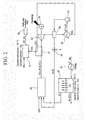
- FIG. 2 is a diagram illustrating a configuration of a system according to a first exemplary embodiment of the present invention.
- the system of the first exemplary embodiment includes an ITM 20 that separates oxygen in the air, an oxy-fuel combustor 10 that combusts using oxygen that is separated at the ITM 20 as an oxidizing agent, a dry-reformer 15 that converts a high concentration of carbon dioxide that is generated through an oxy-fuel combustion reaction to synthetic gases CO and H 2 , and a synthesizer 50 that converts a synthetic gas to methanol.
- a reaction temperature of oxygen separation is about 850 °C and an operation pressure thereof is about 1 bar, and a method of raising a temperature of supplied air by passing it through a separate heat exchanger or installing a heater 21 at the outside of the ITM 20 may be used.
- An oxy-fuel combustion reaction is a reaction of Equation 1, and when a natural gas CH 4 that is supplied from the outside to the oxy-fuel combustor 10, oxygen that is separated at the ITM 20, and steam H 2 O that is separated from exhaust gas of the oxy-fuel combustor 10 to be circulated are injected into the oxy-fuel combustor 10 to perform a combustion reaction, carbon dioxide and steam are generated as an exhaust gas.
- the discharged exhaust gas drives a turbine 12 via a first heat exchanger 11, and a generator 13 that is connected to the same shaft as the turbine 12 generates electricity.
- the exhaust gas having passed through the turbine 12 passes through a second heat exchanger 30, and the exhaust gas having passed through the second heat exchanger 30 is separated into carbon dioxide and steam by a heater 31.
- a temperature of the separated carbon dioxide is raised in the first heat exchanger 11, and the separated carbon dioxide is supplied to the dry-reformer 15. Further, the separated steam is sent to the second heat exchanger 30 by an air blower 32, and a temperature thereof is raised in the second heat exchanger 30, and thus the separated steam is supplied to the oxy-fuel combustor 10.
- a 3-way valve 34 may be attached. The 3-way valve 34 adjusts a quantity of steam that is injected into the oxy-fuel combustor 10, thereby performing a function of adjusting system efficiency.
- the dry-reformer 15 has an operation temperature of about 700 °C and an operation pressure of 1 bar, and as described above, carbon dioxide is separated and circulated from exhaust gas that is discharged from the oxy-fuel combustor 10, the temperature of the carbon dioxide is raised in the first heat exchanger 11, and the carbon dioxide is supplied to the dry-reformer 15.
- Equation 2 a dry-reforming reaction of Equation 2 occurs. CH 4 + C ⁇ O 2 ⁇ 2 ⁇ CO + 2 ⁇ H 2
- the dry-reforming reaction of Equation 2 is a reaction that receives supply of 1 mole of methane and 1 mole of carbon dioxide to generate 2 moles of carbon monoxide and 2 moles of hydrogen after a reforming reaction.
- the dry-reformer 15 generates carbon monoxide and hydrogen using a natural gas from the outside and carbon dioxide that is generated in an oxy-fuel combustion reaction.
- Carbon monoxide and hydrogen that are generated in the dry-reformer 15 may be converted and synthesized into a useful chemical material or a new fuel such as methanol, ketone, or carbonate via the synthesizer 50.
- the synthesizer 50 may be installed at the rear end of the dry-reformer 15.
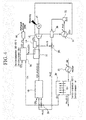
- FIG. 3 is a diagram illustrating a configuration of a system according to a second exemplary embodiment of the present invention.
- the system of the second exemplary embodiment further includes a co-electrolysis device 60 that converts carbon dioxide and steam to a synthetic gas and oxygen by applying heat and electrical energy in the foregoing first exemplary embodiment.
- An exhaust gas that is formed with steam and carbon dioxide that are discharged from an oxy-fuel combustor 10 drives a turbine 12 via a first heat exchanger 11, and the generator 13 that is connected to the same shaft as the turbine 12 generates electricity.
- An exhaust gas having passed through the turbine 12 is branched to flow while advancing through a 3-way valve 61 to a second heat exchanger 30 and flow while advancing to the co-electrolysis device 60.
- the flow advancing to the co-electrolysis device 60 goes through a co-electrolysis process in which carbon dioxide and steam of an exhaust gas are electrolyzed together to be converted into a synthetic gas and oxygen.
- a co-electrolysis process is a process of converting to a synthetic gas and oxygen by applying heat and electrical energy. As described above, in a co-electrolysis process, because heat and electrical energy are required, midnight power or surplus power and thermal energy from new reproduction energy may be used.
- Power from new reproduction energy such as wind power and sun power may perform a co-electrolysis process with the same method as a method using midnight electricity.
- wasted power may be used and in addition to a synthetic gas as a product, and oxygen is additionally produced and thus a quantity of oxygen that should be produced in the ITM 20 may be reduced such that energy that is consumed in the ITM 20 may be relatively reduced.
- Oxygen that is generated in the co-electrolysis device 60 is mixed with oxygen that is separated at the ITM 20 in a mixer 62 to be supplied to the oxy-fuel combustor 10.
- Carbon monoxide and hydrogen that are generated in the dry-reformer 15 or the co-electrolysis device 60 may be converted and synthesized into a useful chemical material or a new fuel such as methanol, ketone, or carbonate via the synthesizer 50.
- the synthesizer 50 may be installed at the rear end of the dry-reformer 15 or the co-electrolysis device 60.
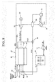
- FIG. 4 is a diagram illustrating a configuration of a system according to a third exemplary embodiment of the present invention.
- the system of the third exemplary embodiment includes an ITM 20 that separates oxygen in the air, an oxy-fuel combustor 10 that combusts using oxygen that is separated at the ITM 20 as an oxidizing agent, a tri-reformer 16 that converts a high concentration of carbon dioxide and steam that are generated through an oxy-fuel combustion reaction, a natural gas that is supplied from the outside, oxygen that is separated at the ITM 20 to synthetic gases CO and H 2 , and a synthesizer 50 that converts a synthetic gas to methanol.
- a tri-reforming reaction is performed and is represented as in Equation 3. 4 ⁇ CH 4 + 2.5 ⁇ O 2 + CO 2 + H 2 ⁇ O ⁇ 4 ⁇ CO + CO 2 + 2 ⁇ H 2 ⁇ O + 7 ⁇ H 2
- the tri-reforming reaction should additionally inject oxygen and steam, unlike a dry-reforming reaction that injects only carbon dioxide and natural gas.
- oxygen that is separated at the ITM 20 is adjusted to be injected into the oxy-fuel combustor 10 or the tri-reformer 16 by a 3-way valve 35.
- a discharged exhaust gas is moved to a first heat exchanger 11.
- the exhaust gas having passed through the first heat exchanger 11 drives a turbine 12, and a generator 13 that is connected to the same shaft as the turbine 12 generates electricity.
- the tri-reformer 16 has an operation temperature of about 800-900 °C and an operation pressure of 5 bar, and is operated at a higher temperature and pressure than the dry-reformer 15 that is described in the first and second exemplary embodiments, and in the first heat exchanger 11, after the temperature of steam and carbon dioxide are fully raised, the steam and carbon dioxide should be supplied to the tri-reformer 16.
- Carbon monoxide and hydrogen that are generated in the tri-reformer 16 may be converted and synthesized into a useful chemical material or a new fuel such as methanol, ketone, or carbonate via the synthesizer 50.
- FIG. 5 is a diagram illustrating a configuration of a system according to a fourth exemplary embodiment of the present invention.
- the system of the fourth exemplary embodiment further includes a co-electrolysis device 60 that converts carbon dioxide and steam to a synthetic gas and oxygen by applying heat and electrical energy in the foregoing third exemplary embodiment.
- An exhaust gas, having passed through a turbine 12 is branched to flow while advancing through a 3-way valve 61 to a second heat exchanger 30 and flow while advancing to the co-electrolysis device 60.
- the flow while advancing to the co-electrolysis device 60 goes through a co-electrolysis process in which carbon dioxide and steam of exhaust gas are electrolyzed together to be converted into a synthetic gas and oxygen.
- Oxygen that is generated in the co-electrolysis device 60 is mixed with oxygen that is separated at an ITM 20 in a mixer 62, and is supplied to an oxy-fuel combustor 10 or a tri-reformer 16 by a 3-way valve 35.
- Carbon monoxide and hydrogen that are generated in the tri-reformer 16 or the co-electrolysis device 60 may be converted and synthesized into a useful chemical material or a new fuel such as methanol, ketone, or carbonate via a synthesizer 50.
- the system of the fifth exemplary embodiment includes an ITM 20 that separates oxygen in the air, an integral reactor 40 that includes a dry-reformer 41 that converts a high concentration of carbon dioxide that is generated through an oxy-fuel combustion reaction to synthetic gases CO and H 2 at an outer wall of an oxy-fuel combustor 10, and a synthesizer 50 that converts a synthetic gas to methanol.
- a conventional oxy-fuel combustor has a high single flame temperature by using oxygen as an oxidizing agent and thus an outer wall of the combustor is damaged, and in order to prevent this, a reaction is performed in a form that lowers combustion temperature by injecting steam.
- a heat source for generating steam should exist and separate pump power for driving steam is required, and thus there are problems that a system configuration becomes complex and that entire system efficiency is deteriorated.
- the oxy-fuel combustor 10 discharges carbon dioxide and steam (or oxygen) as an exhaust gas.
- the discharged exhaust gas drives the turbine 12, and electricity is generated in the generator 13 that is disposed at the same shaft as the turbine 12.
- An exhaust gas having passed through a turbine 12 passes through a second heat exchanger 30 and is separated into carbon dioxide and steam by a heater 31.
- the separated steam is again injected into the second heat exchanger 30 by an air blower 32 and a temperature thereof is raised, and the separated steam is again circulated to the oxy-fuel combustor 10.
- a 3-way valve 34 may adjust a flow rate thereof.
- Carbon monoxide and hydrogen that are generated in the dry-reformer 41 may be converted and synthesized into a useful chemical material or a new fuel such as methanol, ketone, or carbonate via the synthesizer 50.
- FIG. 7 is a diagram illustrating a configuration of a system according to a sixth exemplary embodiment of the present invention.
- the system of the sixth exemplary embodiment further includes a co-electrolysis device 60 that converts carbon dioxide and steam to a synthetic gas and oxygen by applying heat and electrical energy in the foregoing fifth exemplary embodiment.
- An exhaust gas having passed through a turbine 12, is branched to flow while advancing to the co-electrolysis device 60 through a 3-way valve 61 and flow while advancing to a second heat exchanger 30.
- the flow advancing to the co-electrolysis device 60 goes through a co-electrolysis process in which carbon dioxide and steam of an exhaust gas are electrolyzed together to be converted into a synthetic gas and oxygen.
- Oxygen that is generated in the co-electrolysis device 60 is mixed with oxygen that is separated at an ITM 20 in a mixer 62 to be supplied to an oxy-fuel combustor 10.
- Carbon monoxide and hydrogen that are generated in a dry-reformer 41 or the co-electrolysis device 60 may be converted and synthesized into a useful chemical material or a new fuel such as methanol, ketone, or carbonate via a synthesizer 50.
- FIG. 8 is a diagram illustrating a configuration of a system according to a seventh exemplary embodiment of the present invention.
- the system of the seventh exemplary embodiment includes an ITM 20 that separates oxygen in the air, an integral reactor 40 that includes a tri-reformer 42 at an outer wall of an oxy-fuel combustor 10, and a synthesizer 50 that converts a synthetic gas to methanol.
- Oxygen that is separated at the ITM 20 is supplied to the oxy-fuel combustor 10 or the tri-reformer 42 by a 3-way valve 22.
- oxygen that is separated at the ITM 20 as an oxidizing agent, an oxy-fuel combustion reaction is performed in the oxy-fuel combustor 10, and carbon dioxide and steam (or oxygen) are discharged as an exhaust gas.
- the exhaust gas having passed through the turbine 12 passes through a second heat exchanger 30, and the exhaust gas having passed through the second heat exchanger 30 is separated into carbon dioxide and steam by the heater 31.
- the separated carbon dioxide is supplied to the tri-reformer 42 to perform a tri-reforming reaction that is represented in Equation 3.
- a tri-reforming reaction occurs, and the tri-reformer 42 receives supply of a natural gas that is supplied from the outside, carbon dioxide that is separated at the heater 31, steam having passed through the first heat exchanger, and oxygen that is separated at the ITM 20, and thus a reforming reaction occurs.
- a tri-reforming reaction additionally requires supply of steam and oxygen, and thus the flow of the present system is formed.
- FIG. 9 is a illustrating a configuration of a system according to an eighth exemplary embodiment of the present invention.
- the system of the eighth exemplary embodiment further includes a co-electrolysis device 60 that converts carbon dioxide and steam into a synthetic gas and oxygen by applying heat and electrical energy in the foregoing seventh exemplary embodiment.
- the flow advancing to the co-electrolysis device 60 goes through a co-electrolysis process in which carbon dioxide and steam of an exhaust gas are electrolyzed together to be converted into a synthetic gas and oxygen.
- Oxygen that is generated in the co-electrolysis device 60 is mixed with oxygen that is separated at an ITM 20 in a mixer 62, and is supplied to an oxy-fuel combustor 10 or a tri-reformer 42 by a 3-way valve 35.
- Carbon monoxide and hydrogen that are generated in the tri-reformer 42 or the co-electrolysis device 60 may be converted and synthesized into a useful chemical material or a new fuel such as methanol, ketone, or carbonate via a synthesizer 50.
- a synthetic gas that is converted in a reformer can be converted and synthesized into a useful compound material or new fuel such as methanol, ketone, or carbonate via an additional process, there is a merit that the system can have various uses.
- a carbon dioxide conversion system by integrating and producing a tri-reformer or a dry-reformer at an outer wall of an oxy-fuel combustor, heat that may damage the outer wall of the oxy-fuel combustor may be transferred to the tri-reformer or the dry-reformer and thus inflow of steam is unnecessary or a quantity thereof may be reduced, such that energy consumption for generating and driving steam can be reduced.
- a synthetic gas can be converted and synthesized to a new fuel or a useful compound material using midnight power or surplus power and heat energy from new reproduction energy, and thus the system can have various uses.
Landscapes
- Chemical & Material Sciences (AREA)
- Engineering & Computer Science (AREA)
- Chemical Kinetics & Catalysis (AREA)
- Organic Chemistry (AREA)
- General Engineering & Computer Science (AREA)
- Mechanical Engineering (AREA)
- Combustion & Propulsion (AREA)
- Analytical Chemistry (AREA)
- Inorganic Chemistry (AREA)
- Health & Medical Sciences (AREA)
- General Health & Medical Sciences (AREA)
- Biomedical Technology (AREA)
- Environmental & Geological Engineering (AREA)
- General Chemical & Material Sciences (AREA)
- Oil, Petroleum & Natural Gas (AREA)
- Hydrogen, Water And Hydrids (AREA)
- Organic Low-Molecular-Weight Compounds And Preparation Thereof (AREA)
Abstract
Description
- The present invention relates to a carbon dioxide conversion system. More particularly, the present invention relates to an integrated carbon dioxide conversion system for connecting oxy-fuel combustion and a catalytic conversion process.
- Oxy-fuel combustion technology is technology that easily performs collection of carbon dioxide by injecting and combusting oxygen-fuel that removes a nitrogen component occupying about 79 % of air instead of using existing combustion air in an existing air combustion method that is injected into a combustor without removing nitrogen and other components in the air. In technology that recovers carbon dioxide by adapting oxy-fuel combustion, by combusting using a high concentration of oxygen having purity of 95 % or more instead of air as an oxidizing agent, heat is generated. Most of exhaust gas that is generated through oxy-fuel combustion is formed of carbon dioxide and steam, and by recirculating about 70-80 % of the generated exhaust gas to a combustion chamber, a concentration of carbon dioxide of the exhaust gas may be finally concentrated to 80 % or more. In the oxy-fuel combustion technology, when condensing steam as a main component of the discharged exhaust gas, almost an entire amount of carbon dioxide may be recovered, and by storing the recovered carbon dioxide, carbon dioxide and an air pollution material are not discharged.
- As described above, a carbon dioxide conversion system collects a high concentration of carbon dioxide. However, for oxy-fuel combustion, a high concentration of oxygen is required, and in this case, when separating oxygen from the air using an Air Separation Unit (ASU), much energy is consumed and thus there is a drawback that entire system efficiency is lowered.
- Further, in a conventional system, the system is used for collecting, transporting, and storing a high concentration of carbon dioxide that is discharged through oxy-fuel combustion and thus there is a problem that a use value is deteriorated.
- Further, a conventional oxy-fuel combustor uses oxygen as an oxidizing agent and a single flame temperature is high compared with when using air, and as a combustor outer wall may be damaged thereby, in order to reduce the combustion temperature, steam is injected. In this case, there is a problem that a heat source for generating steam should exist and separate pump work for driving the steam is needed.
- The present invention is suggested to solve the above problem, and provides an integrated carbon dioxide conversion system that connects oxy-fuel combustion and a catalyst conversion process and includes an Ion Transfer Membrane (ITM) that separates oxygen in the air, an oxy-fuel combustor that combusts using oxygen that is separated at the ITM as an oxidizing agent, a reformer that converts a high concentration of carbon dioxide that is generated through an oxy-fuel combustion reaction to synthetic gases CO and H2, and a synthesizer that converts the synthetic gases to methanol.
- A carbon dioxide conversion system further including a co-electrolysis device that converts carbon dioxide and steam to a synthetic gas by applying heat and electrical energy and that connects co-electrolysis and catalyst conversion processes using oxy-fuel combustion and new reproduction energy is provided.
- Further, a carbon dioxide conversion system that converts collected carbon dioxide to a new fuel or a useful compound is provided.
- A carbon dioxide conversion system that can increase a life-span of an oxy-fuel combustor and that can improve a conversion rate of a reforming reaction by providing an integral reactor that integrates a reformer at an outer wall of the oxy-fuel combustor is provided.
- An exemplary embodiment of the present invention provides a carbon dioxide conversion system including: an ion transfer membrane that separates oxygen in the air; an oxy-fuel combustor that combusts using oxygen that is separated at the ion transfer membrane as an oxidizing agent; and a dry-reformer that converts carbon dioxide that is generated through an oxy-fuel combustion reaction of the oxy-fuel combustor and methane gas that is supplied from the outside to carbon monoxide and hydrogen by a dry-reforming reaction.
- The carbon dioxide conversion system may further include a co-electrolysis device that converts carbon dioxide and steam that are generated through an oxy-fuel combustion reaction of the oxy-fuel combustor by applying heat and electrical energy to carbon monoxide, hydrogen, and oxygen.
- The carbon dioxide conversion system may further include a synthesizer that converts carbon monoxide and hydrogen that are generated in the dry-reformer or the co-electrolysis device to methanol, ketone, or carbonate.
- The carbon dioxide conversion system may further include a mixer that mixes oxygen that is generated in the co-electrolysis device and oxygen that is separated at the ion transfer membrane, wherein oxygen may be supplied from the mixer to the oxy-fuel combustor.
- Another embodiment of the present invention provides a carbon dioxide conversion system including: an ion transfer membrane that separates oxygen in the air; an oxy-fuel combustor that combusts using oxygen that is separated at the ion transfer membrane as an oxidizing agent; and a tri-reformer that converts carbon dioxide and steam that are generated through an oxy-fuel combustion reaction of the oxy-fuel combustor, methane gas that is supplied from the outside, and oxygen that is separated at the ion transfer membrane to carbon monoxide and hydrogen by a tri-reforming reaction.
- The carbon dioxide conversion system may further include a co-electrolysis device that converts carbon dioxide and steam that are generated through an oxy-fuel combustion reaction of the oxy-fuel combustor by applying heat and electrical energy to carbon monoxide, hydrogen, and oxygen.
- The carbon dioxide conversion system may further include a synthesizer that converts carbon monoxide and hydrogen that are generated in the tri-reformer or the co-electrolysis device to methanol, ketone, or carbonate.
- The carbon dioxide conversion system may further include: a mixer that mixes oxygen that is generated in the co-electrolysis device and oxygen that is separated at the ion transfer membrane; and a 3-way valve that supplies oxygen from the mixer to the oxy-fuel combustor or the tri-reformer.
- A turbine may be rotated using exhaust gas that is discharged from the oxy-fuel combustor, and electricity may be generated through a generator that is connected to the turbine.
- A first heat exchanger may be located at the rear end of the oxy-fuel combustor to raise the temperature of a circulating fluid.
- Steam may be separated from the exhaust gas having passed through the turbine to be supplied to the oxy-fuel combustor.
- Steam may be separated from exhaust gas that is discharged from the oxy-fuel combustor to be supplied to the tri-reformer and the oxy-fuel combustor.
- The carbon dioxide conversion system may further include a 3-way valve that adjusts a flow rate of steam that is supplied to the tri-reformer and the oxy-fuel combustor.
- Yet another embodiment of the present invention provides a carbon dioxide conversion system including: an ion transfer membrane that separates oxygen in the air; and an integral reactor that includes a dry-reformer at an outer wall of an oxy-fuel combustor, wherein at the oxy-fuel combustor of the integral reactor, a combustion reaction occurs using oxygen that is separated at the ion transfer membrane as an oxidizing agent, and the dry-reformer of the integral reactor converts carbon dioxide that is generated through an oxy-fuel combustion reaction of the oxy-fuel combustor and methane gas that is supplied from the outside to carbon monoxide and hydrogen with a dry-reforming reaction.
- The carbon dioxide conversion system may further include a co-electrolysis device that converts carbon dioxide and steam that are generated through an oxy-fuel combustion reaction of the oxy-fuel combustor by applying heat and electrical energy to carbon monoxide, hydrogen, and oxygen.
- The carbon dioxide conversion system may further include a synthesizer that converts carbon monoxide and hydrogen that are generated in the dry-reformer or the co-electrolysis device to methanol, ketone, or carbonate.
- The carbon dioxide conversion system may further include a mixer that mixes oxygen that is generated in the co-electrolysis device and oxygen that is separated at the ion transfer membrane, wherein oxygen may be supplied from the mixer to the oxy-fuel combustor.
- Yet another embodiment of the present invention provides a carbon dioxide conversion system including: an ion transfer membrane that separates oxygen in the air; and an integral reactor that includes a tri-reformer at an outer wall of an oxy-fuel combustor, wherein at the oxy-fuel combustor of the integral reactor, a combustion reaction occurs using oxygen that is separated at the ion transfer membrane as an oxidizing agent, and the tri-reformer of the integral reactor converts carbon dioxide and steam that are generated through an oxy-fuel combustion reaction of the oxy-fuel combustor, methane gas that is supplied from the outside, and oxygen that is separated at the ion transfer membrane to carbon monoxide and hydrogen with a tri-reforming reaction.
- The carbon dioxide conversion system may further include a co-electrolysis device that converts carbon dioxide and steam that are generated through an oxy-fuel combustion reaction of the oxy-fuel combustor by applying heat and electrical energy to carbon monoxide, hydrogen, and oxygen.
- The carbon dioxide conversion system may further include a synthesizer that converts carbon monoxide and hydrogen that are generated in the tri-reformer or the co-electrolysis device to methanol, ketone, or carbonate.
- The carbon dioxide conversion system may further include: a mixer that mixes oxygen that is generated in the co-electrolysis device and oxygen that is separated at the ion transfer membrane; and a 3-way valve that supplies oxygen from the mixer to the oxy-fuel combustor or the tri-reformer.
- A turbine may be rotated using exhaust gas that is discharged from the oxy-fuel combustor, and electricity may be generated through a generator that is connected to the turbine.
- The carbon dioxide conversion system may further include a 3-way valve that separates steam from exhaust gas that is discharged from the oxy-fuel combustor to supply the steam to the oxy-fuel combustor and that adjusts a flow rate of the steam.
- Steam may be separated from exhaust gas that is discharged from the oxy-fuel combustor to be supplied to the tri-reformer and the oxy-fuel combustor.
- The carbon dioxide conversion system may further include a 3-way valve that adjusts a flow rate of steam that is supplied to the tri-reformer and the oxy-fuel combustor.
- According to a carbon dioxide conversion system of the present invention, from an oxygen production viewpoint, compared with an ASU that separates oxygen in the air using an ITM, oxygen production cost is reduced and thus system efficiency is improved.
- Because a synthetic gas that is converted in a reformer can be converted and synthesized to a useful compound material or a new fuel such as methanol, ketone, or carbonate via an additional process, there is a merit that the system can have various uses.
- In a carbon dioxide conversion system according to the present invention, by integrating and producing a tri-reformer or a dry-reformer at an outer wall of an oxy-fuel combustor, heat that may damage the outer wall of the oxy-fuel combustor may be transferred to the tri-reformer or the dry-reformer and thus inflow of steam is unnecessary or a quantity thereof may be reduced such that energy consumption for generating and driving steam can be reduced.
- Further, by improving a transfer rate of heat that is supplied to the tri-reformer or the dry-reformer, a synthetic gas conversion rate can be improved.
- In addition, a synthetic gas can be converted and synthesized to a new fuel or useful compound material using midnight power or surplus power and heat energy from new reproduction energy and thus the carbon dioxide conversion system can have various uses.
-
-
FIG. 1 is a schematic diagram of an oxy-fuel combustion system using a conventional ASU. -
FIGS. 2 to 9 are schematic diagrams of an integrated carbon dioxide conversion system that connects oxy-fuel combustion and a catalyst conversion process or that connects co-electrolysis and catalyst conversion processes using oxy-fuel combustion and new reproduction energy according to an exemplary embodiment of the present invention. - Hereinafter, exemplary embodiments of an integrated carbon dioxide conversion system that connects oxy-fuel combustion and a catalyst conversion process or that connects co-electrolysis and catalyst conversion processes using oxy-fuel combustion and new reproduction energy according to the present invention will be described in detail with reference to the accompanying drawings. Like reference numerals designate like elements throughout the specification. Further, detailed descriptions of well-known functions and structures incorporated herein may be omitted to avoid obscuring the subject matter of the present invention.
-
FIG. 1 is a diagram illustrating an oxy-fuel combustion system using a conventional ASU, and the system includes an oxy-fuel combustor 1, anASU 2, aturbine 3, aheat exchanger 4, aheater 5, anair blower 6, and a generator 7. - In the oxy-
fuel combustor 1, by using separated oxygen as an oxidizing agent, a combustion reaction occurs, and main components of exhaust gas that is discharged from the oxy-fuel combustor 1 are carbon dioxide and steam. Theturbine 3 is driven using an exhaust gas, and the generator 7 that is connected to the same shaft as theturbine 3 generates electricity. - The exhaust gas, having passed through the
turbine 3, is separated into carbon dioxide and steam by theheater 5, and the separated steam is sent to theheat exchanger 4 by theair blower 6. High temperature steam, having passed through theheat exchanger 4, is again recirculated to the oxy-fuel combustor 1. - The foregoing conventional system uses the ASU 2 that separates oxygen in injected air, and in a process of separating oxygen, energy is consumed and thus there is a problem that entire system efficiency is problematic.
- Further, in an oxy-fuel combustion reaction, by using oxygen instead of air as an oxidizing agent, a single flame temperature is high and thus there is a problem that steam should be supplied to the oxy-
fuel combustor 1 and that durability of the oxy-fuel combustor 1 is deteriorated. -
FIG. 2 is a diagram illustrating a configuration of a system according to a first exemplary embodiment of the present invention. - The system of the first exemplary embodiment includes an
ITM 20 that separates oxygen in the air, an oxy-fuel combustor 10 that combusts using oxygen that is separated at theITM 20 as an oxidizing agent, a dry-reformer 15 that converts a high concentration of carbon dioxide that is generated through an oxy-fuel combustion reaction to synthetic gases CO and H2, and asynthesizer 50 that converts a synthetic gas to methanol. - In the
ITM 20, a reaction temperature of oxygen separation is about 850 °C and an operation pressure thereof is about 1 bar, and a method of raising a temperature of supplied air by passing it through a separate heat exchanger or installing aheater 21 at the outside of theITM 20 may be used.
- An oxy-fuel combustion reaction is a reaction of
Equation 1, and when a natural gas CH4 that is supplied from the outside to the oxy-fuel combustor 10, oxygen that is separated at theITM 20, and steam H2O that is separated from exhaust gas of the oxy-fuel combustor 10 to be circulated are injected into the oxy-fuel combustor 10 to perform a combustion reaction, carbon dioxide and steam are generated as an exhaust gas. - The discharged exhaust gas drives a
turbine 12 via afirst heat exchanger 11, and agenerator 13 that is connected to the same shaft as theturbine 12 generates electricity. The exhaust gas having passed through theturbine 12 passes through asecond heat exchanger 30, and the exhaust gas having passed through thesecond heat exchanger 30 is separated into carbon dioxide and steam by aheater 31. - A temperature of the separated carbon dioxide is raised in the
first heat exchanger 11, and the separated carbon dioxide is supplied to the dry-reformer 15. Further, the separated steam is sent to thesecond heat exchanger 30 by anair blower 32, and a temperature thereof is raised in thesecond heat exchanger 30, and thus the separated steam is supplied to the oxy-fuel combustor 10. In order to adjust a quantity of steam that is supplied to the oxy-fuel combustor 10, a 3-way valve 34 may be attached. The 3-way valve 34 adjusts a quantity of steam that is injected into the oxy-fuel combustor 10, thereby performing a function of adjusting system efficiency. - The dry-
reformer 15 has an operation temperature of about 700 °C and an operation pressure of 1 bar, and as described above, carbon dioxide is separated and circulated from exhaust gas that is discharged from the oxy-fuel combustor 10, the temperature of the carbon dioxide is raised in thefirst heat exchanger 11, and the carbon dioxide is supplied to the dry-reformer 15. - In the present exemplary embodiment, a dry-reforming reaction of
Equation 2 occurs.
- The dry-reforming reaction of
Equation 2 is a reaction that receives supply of 1 mole of methane and 1 mole of carbon dioxide to generate 2 moles of carbon monoxide and 2 moles of hydrogen after a reforming reaction. The dry-reformer 15 generates carbon monoxide and hydrogen using a natural gas from the outside and carbon dioxide that is generated in an oxy-fuel combustion reaction. - Carbon monoxide and hydrogen that are generated in the dry-
reformer 15 may be converted and synthesized into a useful chemical material or a new fuel such as methanol, ketone, or carbonate via thesynthesizer 50. - The
synthesizer 50 may be installed at the rear end of the dry-reformer 15. -
FIG. 3 is a diagram illustrating a configuration of a system according to a second exemplary embodiment of the present invention. - The system of the second exemplary embodiment further includes a
co-electrolysis device 60 that converts carbon dioxide and steam to a synthetic gas and oxygen by applying heat and electrical energy in the foregoing first exemplary embodiment. - An exhaust gas that is formed with steam and carbon dioxide that are discharged from an oxy-
fuel combustor 10 drives aturbine 12 via afirst heat exchanger 11, and thegenerator 13 that is connected to the same shaft as theturbine 12 generates electricity. An exhaust gas having passed through theturbine 12 is branched to flow while advancing through a 3-way valve 61 to asecond heat exchanger 30 and flow while advancing to theco-electrolysis device 60. - The flow advancing to the
co-electrolysis device 60 goes through a co-electrolysis process in which carbon dioxide and steam of an exhaust gas are electrolyzed together to be converted into a synthetic gas and oxygen. A co-electrolysis process is a process of converting to a synthetic gas and oxygen by applying heat and electrical energy. As described above, in a co-electrolysis process, because heat and electrical energy are required, midnight power or surplus power and thermal energy from new reproduction energy may be used. - When midnight power is used, in the daytime, conversion to carbon dioxide is performed only with a catalyst chemical process such as a dry-reforming reaction or a tri-reforming reaction, and in the night time, surplus power is available, so carbon dioxide and steam corresponding to a quantity of the surplus power are supplied to the
co-electrolysis device 60 to generate a synthetic gas and oxygen. - Power from new reproduction energy such as wind power and sun power may perform a co-electrolysis process with the same method as a method using midnight electricity. In this way, when the
co-electrolysis device 60 is used, wasted power may be used and in addition to a synthetic gas as a product, and oxygen is additionally produced and thus a quantity of oxygen that should be produced in theITM 20 may be reduced such that energy that is consumed in theITM 20 may be relatively reduced. - Oxygen that is generated in the
co-electrolysis device 60 is mixed with oxygen that is separated at theITM 20 in amixer 62 to be supplied to the oxy-fuel combustor 10. - Carbon monoxide and hydrogen that are generated in the dry-
reformer 15 or theco-electrolysis device 60 may be converted and synthesized into a useful chemical material or a new fuel such as methanol, ketone, or carbonate via thesynthesizer 50. - The
synthesizer 50 may be installed at the rear end of the dry-reformer 15 or theco-electrolysis device 60. -
FIG. 4 is a diagram illustrating a configuration of a system according to a third exemplary embodiment of the present invention. - The system of the third exemplary embodiment includes an
ITM 20 that separates oxygen in the air, an oxy-fuel combustor 10 that combusts using oxygen that is separated at theITM 20 as an oxidizing agent, a tri-reformer 16 that converts a high concentration of carbon dioxide and steam that are generated through an oxy-fuel combustion reaction, a natural gas that is supplied from the outside, oxygen that is separated at theITM 20 to synthetic gases CO and H2, and asynthesizer 50 that converts a synthetic gas to methanol. - Unlike the first and second exemplary embodiments, in the third exemplary embodiment, a tri-reforming reaction is performed and is represented as in
Equation 3.
- The tri-reforming reaction should additionally inject oxygen and steam, unlike a dry-reforming reaction that injects only carbon dioxide and natural gas.
- Therefore, in order to inject oxygen, oxygen that is separated at the
ITM 20 is adjusted to be injected into the oxy-fuel combustor 10 or the tri-reformer 16 by a 3-way valve 35. - In the oxy-
fuel combustor 10, after an oxy-fuel combustion reaction ofEquation 1 is performed, a discharged exhaust gas is moved to afirst heat exchanger 11. The exhaust gas having passed through thefirst heat exchanger 11 drives aturbine 12, and agenerator 13 that is connected to the same shaft as theturbine 12 generates electricity. - The exhaust gas having passed through the
turbine 12 again passes through asecond heat exchanger 30, and the exhaust gas having passed through thesecond heat exchanger 30 is separated into carbon dioxide and steam by aheater 31. The separated steam is injected into thesecond heat exchanger 30 by anair blower 32, and after the temperature thereof is raised at thesecond heat exchanger 30, flow of the separated steam is adjusted from the 3-way valve 34 in a direction of the oxy-fuel combustor 10 or in a direction of the tri-reformer 16. - Steam flowing from the 3-
way valve 34 in a direction of the tri-reformer 16 is injected into amixer 14, and in themixer 14, the steam is mixed with carbon dioxide that is separated at theheater 31 and the temperature thereof is raised at thefirst heat exchanger 11, and the steam is supplied to the tri-reformer 16. - The tri-reformer 16 has an operation temperature of about 800-900 °C and an operation pressure of 5 bar, and is operated at a higher temperature and pressure than the dry-
reformer 15 that is described in the first and second exemplary embodiments, and in thefirst heat exchanger 11, after the temperature of steam and carbon dioxide are fully raised, the steam and carbon dioxide should be supplied to the tri-reformer 16. - A temperature of oxygen that is separated at the
ITM 20 approximately corresponds to 850 °C, which is a reaction temperature of tri-reforming, and oxygen may be supplied without passing through a heat exchanger. - Carbon monoxide and hydrogen that are generated in the tri-reformer 16 may be converted and synthesized into a useful chemical material or a new fuel such as methanol, ketone, or carbonate via the
synthesizer 50. -
FIG. 5 is a diagram illustrating a configuration of a system according to a fourth exemplary embodiment of the present invention. - The system of the fourth exemplary embodiment further includes a
co-electrolysis device 60 that converts carbon dioxide and steam to a synthetic gas and oxygen by applying heat and electrical energy in the foregoing third exemplary embodiment. - An exhaust gas, having passed through a
turbine 12 is branched to flow while advancing through a 3-way valve 61 to asecond heat exchanger 30 and flow while advancing to theco-electrolysis device 60. - The flow while advancing to the
co-electrolysis device 60 goes through a co-electrolysis process in which carbon dioxide and steam of exhaust gas are electrolyzed together to be converted into a synthetic gas and oxygen. - Oxygen that is generated in the
co-electrolysis device 60 is mixed with oxygen that is separated at anITM 20 in amixer 62, and is supplied to an oxy-fuel combustor 10 or a tri-reformer 16 by a 3-way valve 35. - Carbon monoxide and hydrogen that are generated in the tri-reformer 16 or the
co-electrolysis device 60 may be converted and synthesized into a useful chemical material or a new fuel such as methanol, ketone, or carbonate via asynthesizer 50. -
FIG. 6 is a diagram illustrating a configuration of a system according to a fifth exemplary embodiment of the present invention. - The system of the fifth exemplary embodiment includes an
ITM 20 that separates oxygen in the air, anintegral reactor 40 that includes a dry-reformer 41 that converts a high concentration of carbon dioxide that is generated through an oxy-fuel combustion reaction to synthetic gases CO and H2 at an outer wall of an oxy-fuel combustor 10, and asynthesizer 50 that converts a synthetic gas to methanol. - A conventional oxy-fuel combustor has a high single flame temperature by using oxygen as an oxidizing agent and thus an outer wall of the combustor is damaged, and in order to prevent this, a reaction is performed in a form that lowers combustion temperature by injecting steam. In this case, a heat source for generating steam should exist and separate pump power for driving steam is required, and thus there are problems that a system configuration becomes complex and that entire system efficiency is deteriorated.
- Therefore, in the fifth exemplary embodiment, by integrating the dry-
reformer 41 at an outer wall of the cylindrical oxy-fuel combustor 10, theintegral reactor 40 is introduced to the present system. Thereby, heat that is generated in the oxy-fuel combustor 10 is transferred to the dry-reformer 41 to lower a single flame temperature of the oxy-fuel combustor 10 and thus a quantity of injected steam is reduced, compared with an existing oxy-fuel combustor, and thus power consumption of a pump and heat for generating steam can be reduced such that a configuration of the system may be simplified. - After a reaction of
Equation 1, the oxy-fuel combustor 10 discharges carbon dioxide and steam (or oxygen) as an exhaust gas. The discharged exhaust gas drives theturbine 12, and electricity is generated in thegenerator 13 that is disposed at the same shaft as theturbine 12. - An exhaust gas having passed through a
turbine 12 passes through asecond heat exchanger 30 and is separated into carbon dioxide and steam by aheater 31. The separated steam is again injected into thesecond heat exchanger 30 by anair blower 32 and a temperature thereof is raised, and the separated steam is again circulated to the oxy-fuel combustor 10. Before the steam is injected into the oxy-fuel combustor 10, a 3-way valve 34 may adjust a flow rate thereof. - The separated carbon dioxide is supplied to the dry-
reformer 41, and the supplied carbon dioxide and a natural gas that is injected from the outside generate a synthetic gas (carbon monoxide, hydrogen) through a dry-reforming reaction ofEquation 2. - Carbon monoxide and hydrogen that are generated in the dry-
reformer 41 may be converted and synthesized into a useful chemical material or a new fuel such as methanol, ketone, or carbonate via thesynthesizer 50. - Due to introduction of the
integral reactor 40 that integrates the oxy-fuel combustor 10 and the dry-reformer 41, a configuration of the system can be further simplified. -
FIG. 7 is a diagram illustrating a configuration of a system according to a sixth exemplary embodiment of the present invention. - The system of the sixth exemplary embodiment further includes a
co-electrolysis device 60 that converts carbon dioxide and steam to a synthetic gas and oxygen by applying heat and electrical energy in the foregoing fifth exemplary embodiment. - An exhaust gas, having passed through a
turbine 12, is branched to flow while advancing to theco-electrolysis device 60 through a 3-way valve 61 and flow while advancing to asecond heat exchanger 30. - The flow advancing to the
co-electrolysis device 60 goes through a co-electrolysis process in which carbon dioxide and steam of an exhaust gas are electrolyzed together to be converted into a synthetic gas and oxygen. - Oxygen that is generated in the
co-electrolysis device 60 is mixed with oxygen that is separated at anITM 20 in amixer 62 to be supplied to an oxy-fuel combustor 10. - Carbon monoxide and hydrogen that are generated in a dry-
reformer 41 or theco-electrolysis device 60 may be converted and synthesized into a useful chemical material or a new fuel such as methanol, ketone, or carbonate via asynthesizer 50. -
FIG. 8 is a diagram illustrating a configuration of a system according to a seventh exemplary embodiment of the present invention. - The system of the seventh exemplary embodiment includes an
ITM 20 that separates oxygen in the air, anintegral reactor 40 that includes a tri-reformer 42 at an outer wall of an oxy-fuel combustor 10, and asynthesizer 50 that converts a synthetic gas to methanol. - Oxygen that is separated at the
ITM 20 is supplied to the oxy-fuel combustor 10 or the tri-reformer 42 by a 3-way valve 22. By using oxygen that is separated at theITM 20 as an oxidizing agent, an oxy-fuel combustion reaction is performed in the oxy-fuel combustor 10, and carbon dioxide and steam (or oxygen) are discharged as an exhaust gas. - The discharged exhaust gas drives a
turbine 12, and electricity may be generated by agenerator 13 that is disposed at the same shaft as theturbine 12. - The exhaust gas having passed through the
turbine 12 passes through asecond heat exchanger 30, and the exhaust gas having passed through thesecond heat exchanger 30 is separated into carbon dioxide and steam by theheater 31. - The separated carbon dioxide is supplied to the tri-reformer 42 to perform a tri-reforming reaction that is represented in
Equation 3. - The separated steam is again injected into the
second heat exchanger 30 by anair blower 32, and steam of which a temperature is raised in thesecond heat exchanger 30 flows in a direction of the tri-reformer 42 or the oxy-fuel combustor 10. A 3-way valve 34 that adjusts the flow may be further provided. - In the tri-reformer 42, a tri-reforming reaction occurs, and the tri-reformer 42 receives supply of a natural gas that is supplied from the outside, carbon dioxide that is separated at the
heater 31, steam having passed through the first heat exchanger, and oxygen that is separated at theITM 20, and thus a reforming reaction occurs. Unlike a dry-reforming reaction that is illustrated in the fifth and sixth exemplary embodiments, a tri-reforming reaction additionally requires supply of steam and oxygen, and thus the flow of the present system is formed. - Carbon monoxide and hydrogen that are generated in the tri-reformer 42 may be converted and synthesized into a useful chemical material or a new fuel such as methanol, ketone, or carbonate via the
synthesizer 50. -
FIG. 9 is a illustrating a configuration of a system according to an eighth exemplary embodiment of the present invention. - The system of the eighth exemplary embodiment further includes a
co-electrolysis device 60 that converts carbon dioxide and steam into a synthetic gas and oxygen by applying heat and electrical energy in the foregoing seventh exemplary embodiment. - An exhaust gas having passed through a
turbine 12 is branched to flow while advancing from a 3-way valve 61 to asecond heat exchanger 30 and flow while advancing to theco-electrolysis device 60. - The flow advancing to the
co-electrolysis device 60 goes through a co-electrolysis process in which carbon dioxide and steam of an exhaust gas are electrolyzed together to be converted into a synthetic gas and oxygen. - Oxygen that is generated in the
co-electrolysis device 60 is mixed with oxygen that is separated at anITM 20 in amixer 62, and is supplied to an oxy-fuel combustor 10 or a tri-reformer 42 by a 3-way valve 35. - Carbon monoxide and hydrogen that are generated in the tri-reformer 42 or the
co-electrolysis device 60 may be converted and synthesized into a useful chemical material or a new fuel such as methanol, ketone, or carbonate via asynthesizer 50. - While this invention has been described in connection with what is presently considered to be practical exemplary embodiments, it is to be understood that the invention is not limited to the disclosed embodiments, but, on the contrary, is intended to cover various modifications and equivalent arrangements included within the spirit and scope of the appended claims. The scope of the present invention should be analyzed by the appended claims, and all changes, modifications, and alterations should be seen as within the scope of the present invention.
- According to a carbon dioxide conversion system of the present invention, from an oxygen production viewpoint, compared with an ASU that separates oxygen in the air using an ITM, an oxygen production cost is reduced and thus system efficiency is improved.
- Because a synthetic gas that is converted in a reformer can be converted and synthesized into a useful compound material or new fuel such as methanol, ketone, or carbonate via an additional process, there is a merit that the system can have various uses.
- In a carbon dioxide conversion system according to the present invention, by integrating and producing a tri-reformer or a dry-reformer at an outer wall of an oxy-fuel combustor, heat that may damage the outer wall of the oxy-fuel combustor may be transferred to the tri-reformer or the dry-reformer and thus inflow of steam is unnecessary or a quantity thereof may be reduced, such that energy consumption for generating and driving steam can be reduced.
- Further, by improving a transfer rate of heat that is supplied to the tri-reformer or the dry-reformer, a synthetic gas conversion rate can be improved.
- In addition, a synthetic gas can be converted and synthesized to a new fuel or a useful compound material using midnight power or surplus power and heat energy from new reproduction energy, and thus the system can have various uses.
Claims (25)
- A carbon dioxide conversion system, comprising:an ion transfer membrane that separates oxygen in the air;an oxy-fuel combustor that combusts using oxygen that is separated at the ion transfer membrane as an oxidizing agent; anda dry-reformer that converts carbon dioxide that is generated through an oxy-fuel combustion reaction of the oxy-fuel combustor and methane gas that is supplied from the outside to carbon monoxide and hydrogen by a dry-reforming reaction.
- The carbon dioxide conversion system of claim 1, further comprising a co-electrolysis device that converts carbon dioxide and steam that are generated through an oxy-fuel combustion reaction of the oxy-fuel combustor by applying heat and electrical energy to carbon monoxide, hydrogen, and oxygen.
- The carbon dioxide conversion system of claim 2, further comprising a synthesizer that converts carbon monoxide and hydrogen that are generated in the dry-reformer or the co-electrolysis device to methanol, ketone, or carbonate.
- The carbon dioxide conversion system of claim 2, further comprising a mixer that mixes oxygen that is generated in the co-electrolysis device and oxygen that is separated at the ion transfer membrane, wherein oxygen is supplied from the mixer to the oxy-fuel combustor.
- A carbon dioxide conversion system, comprising:an ion transfer membrane that separates oxygen in the air;an oxy-fuel combustor that combusts using oxygen that is separated at the ion transfer membrane as an oxidizing agent; anda tri-reformer that converts carbon dioxide and steam that are generated through an oxy-fuel combustion reaction of the oxy-fuel combustor, methane gas that is supplied from the outside, and oxygen that is separated at the ion transfer membrane to carbon monoxide and hydrogen by a tri-reforming reaction.
- The carbon dioxide conversion system of claim 5, further comprising a co-electrolysis device that converts carbon dioxide and steam that are generated through an oxy-fuel combustion reaction of the oxy-fuel combustor by applying heat and electrical energy to carbon monoxide, hydrogen, and oxygen.
- The carbon dioxide conversion system of claim 6, further comprising a synthesizer that converts carbon monoxide and hydrogen that are generated in the tri-reformer or the co-electrolysis device to methanol, ketone, or carbonate.
- The carbon dioxide conversion system of claim 6, further comprising:a mixer that mixes oxygen that is generated in the co-electrolysis device and oxygen that is separated at the ion transfer membrane; anda 3-way valve that supplies oxygen from the mixer to the oxy-fuel combustor or the tri-reformer.
- The carbon dioxide conversion system of any one of claims 1 to 8, wherein a turbine is rotated using exhaust gas that is discharged from the oxy-fuel combustor, and electricity is generated through a generator that is connected to the turbine.
- The carbon dioxide conversion system of any one of claims 1 to 8, wherein a first heat exchanger is located at the rear end of the oxy-fuel combustor to raise the temperature of a circulating fluid.
- The carbon dioxide conversion system of claim 9, wherein steam is separated from exhaust gas having passed through the turbine to be supplied to the oxy-fuel combustor.
- The carbon dioxide conversion system of any one of claims 5 to 8, wherein steam is separated from exhaust gas that is discharged from the oxy-fuel combustor to be supplied to the tri-reformer and the oxy-fuel combustor.
- The carbon dioxide conversion system of claim 12, further comprising a 3-way valve that adjusts a flow rate of steam that is supplied to the tri-reformer and the oxy-fuel combustor.
- A carbon dioxide conversion system, comprising:an ion transfer membrane that separates oxygen in the air; andan integral reactor that includes a dry-reformer at an outer wall of an oxy-fuel combustor,wherein at the oxy-fuel combustor of the integral reactor, a combustion reaction occurs using oxygen that is separated at the ion transfer membrane as an oxidizing agent, andthe dry-reformer of the integral reactor converts carbon dioxide that is generated through an oxy-fuel combustion reaction of the oxy-fuel combustor and methane gas that is supplied from the outside to carbon monoxide and hydrogen with a dry-reforming reaction.
- The carbon dioxide conversion system of claim 14, further comprising a co-electrolysis device that converts carbon dioxide and steam that are generated through an oxy-fuel combustion reaction of the oxy-fuel combustor by applying heat and electrical energy to carbon monoxide, hydrogen, and oxygen.
- The carbon dioxide conversion system of claim 15, further comprising a synthesizer that converts carbon monoxide and hydrogen that are generated in the dry-reformer or the co-electrolysis device to methanol, ketone, or carbonate.
- The carbon dioxide conversion system of claim 15, further comprising a mixer that mixes oxygen that is generated in the co-electrolysis device and oxygen that is separated at the ion transfer membrane, wherein oxygen is supplied from the mixer to the oxy-fuel combustor.
- A carbon dioxide conversion system, comprising:an ion transfer membrane that separates oxygen in the air; andan integral reactor that includes a tri-reformer at an outer wall of an oxy-fuel combustor,wherein at the oxy-fuel combustor of the integral reactor, a combustion reaction occurs using oxygen that is separated at the ion transfer membrane as an oxidizing agent, andthe tri-reformer of the integral reactor converts carbon dioxide and steam that are generated through an oxy-fuel combustion reaction of the oxy-fuel combustor, methane gas that is supplied from the outside, and oxygen that is separated at the ion transfer membrane to carbon monoxide and hydrogen with a tri-reforming reaction.
- The carbon dioxide conversion system of claim 18, further comprising a co-electrolysis device that converts carbon dioxide and steam that are generated through an oxy-fuel combustion reaction of the oxy-fuel combustor by applying heat and electrical energy to carbon monoxide, hydrogen, and oxygen.
- The carbon dioxide conversion system of claim 19, further comprising a synthesizer that converts carbon monoxide and hydrogen that are generated in the tri-reformer or the co-electrolysis device to methanol, ketone, or carbonate.
- The carbon dioxide conversion system of claim 19, further comprising:a mixer that mixes oxygen that is generated in the co-electrolysis device and oxygen that is separated at the ion transfer membrane; anda 3-way valve that supplies oxygen from the mixer to the oxy-fuel combustor or the tri-reformer.
- The carbon dioxide conversion system of any one of claims 14 to 21, wherein a turbine is rotated using exhaust gas that is discharged from the oxy-fuel combustor, and electricity is generated through a generator that is connected to the turbine.
- The carbon dioxide conversion system of any one of claims 14 to 17, further comprising a 3-way valve that separates steam from exhaust gas that is discharged from the oxy-fuel combustor to supply the steam to the oxy-fuel combustor and that adjusts a flow rate of the steam.
- The carbon dioxide conversion system of any one of claims 18 to 21, wherein steam is separated from exhaust gas that is discharged from the oxy-fuel combustor to be supplied to the tri-reformer and the oxy-fuel combustor.
- The carbon dioxide conversion system of claim 24, further comprising a 3-way valve that adjusts a flow rate of steam that is supplied to the tri-reformer and the oxy-fuel combustor.
Applications Claiming Priority (3)
| Application Number | Priority Date | Filing Date | Title |
|---|---|---|---|
| KR1020120122682A KR101460748B1 (en) | 2012-10-31 | 2012-10-31 | The co2 conversion system integrating oxyfuel combustion and catalytic reforming |
| KR1020120122681A KR101379377B1 (en) | 2012-10-31 | 2012-10-31 | The co2 conversion system intergrating oxyfuel combustion, catalytic reforming and coelectrolysis |
| PCT/KR2013/008768 WO2014069796A1 (en) | 2012-10-31 | 2013-09-30 | Integrated carbon dioxide conversion system for connecting oxy-fuel combustion and catalytic conversion process |
Publications (3)
| Publication Number | Publication Date |
|---|---|
| EP2915779A1 true EP2915779A1 (en) | 2015-09-09 |
| EP2915779A4 EP2915779A4 (en) | 2017-01-25 |
| EP2915779B1 EP2915779B1 (en) | 2019-11-06 |
Family
ID=50627648
Family Applications (1)
| Application Number | Title | Priority Date | Filing Date |
|---|---|---|---|
| EP13850853.6A Active EP2915779B1 (en) | 2012-10-31 | 2013-09-30 | Integrated carbon dioxide conversion system for connecting oxy-fuel combustion and catalytic conversion process |
Country Status (4)
| Country | Link |
|---|---|
| US (1) | US10180253B2 (en) |
| EP (1) | EP2915779B1 (en) |
| JP (1) | JP6078655B2 (en) |
| WO (1) | WO2014069796A1 (en) |
Cited By (1)
| Publication number | Priority date | Publication date | Assignee | Title |
|---|---|---|---|---|
| ES2737875A1 (en) * | 2018-07-16 | 2020-01-16 | Univ Sevilla | CO2 CAPTURE INSTALLATION AND PROCEDURE |
Families Citing this family (19)
| Publication number | Priority date | Publication date | Assignee | Title |
|---|---|---|---|---|
| WO2017065038A1 (en) * | 2015-10-16 | 2017-04-20 | 寛治 泉 | Engine system performing continuous combustion of oxygen and oxygen-enriched air |
| US20180340454A1 (en) * | 2015-11-13 | 2018-11-29 | New Fg Co, Llc | Open Thermodynamic Cycle Utilizing Supercritical Carbon Dioxide Without Compressors |
| CN107587942A (en) * | 2016-07-08 | 2018-01-16 | 华北电力大学(保定) | A Technology of Photodecomposing CO2 Supplementary Combustion Power System |
| JP6748802B2 (en) * | 2016-07-31 | 2020-09-02 | 寛治 泉 | An engine system that continuously burns hydrogen and enriched oxygen air. |
| EP3814274B1 (en) | 2018-06-29 | 2022-05-04 | Shell Internationale Research Maatschappij B.V. | Electrically heated reactor and a process for gas conversions using said reactor |
| TWI855013B (en) | 2018-12-11 | 2024-09-11 | 日商綠淨星球股份有限公司 | Heat utilization system and heating device |
| US11149636B2 (en) * | 2019-03-01 | 2021-10-19 | Richard Alan Callahan | Turbine powered electricity generation |
| US11149634B2 (en) * | 2019-03-01 | 2021-10-19 | Richard Alan Callahan | Turbine powered electricity generation |
| US11162681B2 (en) | 2019-10-28 | 2021-11-02 | King Fahd University Of Petroleum And Minerals | Integrated ITM micromixer burner of shell and tube design for clean combustion in gas turbines |
| US12544728B2 (en) | 2019-12-23 | 2026-02-10 | Shell Usa, Inc. | Electrically heated reactor, a furnace comprising said reactor and a method for gas conversions using said reactor |
| US12545592B2 (en) | 2020-05-18 | 2026-02-10 | Topsoe A/S | Method for the control of pressure in a loop for the preparation of ammonia or methanol |
| TWI895401B (en) * | 2020-05-18 | 2025-09-01 | 丹麥商托普索公司 | Method for the control of pressure in a loop for the preparation of ammonia or methanol |
| WO2022160060A1 (en) * | 2021-01-29 | 2022-08-04 | Industriasys Corp. | Zero emission power generation systems and methods |
| KR102333666B1 (en) * | 2021-05-11 | 2021-12-02 | 한국기계연구원 | Co2-free hydrogen production system and hydrogen production method |
| KR20260028671A (en) | 2023-04-21 | 2026-03-04 | 셰브런 유.에스.에이.인크. | Membrane pre-concentration of carbon dioxide from exhaust gas sources |
| AU2024259977A1 (en) * | 2023-04-25 | 2025-11-13 | Nucor Corporation | Attenuated combustion for clean power and hydrogen capture |
| WO2024257467A1 (en) * | 2023-06-12 | 2024-12-19 | 株式会社伊原工業 | Method for producing carbon monoxide or synthesis gas, and method for producing chemical product, methane or propane |
| WO2025208136A1 (en) * | 2024-03-29 | 2025-10-02 | Chevron U.S.A. Inc. | Integrated tri-reforming system and method |
| US12428296B1 (en) | 2024-05-10 | 2025-09-30 | Nucor Corporation | Process for generating clean power and hydrogen |
Family Cites Families (32)
| Publication number | Priority date | Publication date | Assignee | Title |
|---|---|---|---|---|
| DE69229839T2 (en) * | 1991-01-29 | 2000-02-10 | Mitsubishi Heavy Ind Ltd | Method of producing methanol using the heat of a nuclear power plant |
| JP3225078B2 (en) * | 1992-03-24 | 2001-11-05 | 東洋エンジニアリング株式会社 | Catalyst for syngas production |
| US5714657A (en) * | 1994-03-11 | 1998-02-03 | Devries; Louis | Natural gas conversion to higher hydrocarbons |
| JPH0925101A (en) * | 1995-07-10 | 1997-01-28 | Agency Of Ind Science & Technol | Method for reforming methane with carbon dioxide and catalyst used for the same |
| MY128194A (en) * | 1997-04-11 | 2007-01-31 | Chiyoda Corp | Process for the production of synthesis gas |
| ATE273238T1 (en) | 1997-04-11 | 2004-08-15 | Chiyoda Chem Eng Construct Co | CATALYST FOR PRODUCING SYNTHESIS GAS AND METHOD FOR PRODUCING CARBON MONOXIDE |
| DE69825884D1 (en) | 1997-04-11 | 2004-09-30 | Chiyoda Chem Eng Construct Co | METHOD FOR PRODUCING SYNTHESIS GAS BY means of OUTOTHERM REFORMING |
| US6149714A (en) | 1997-06-05 | 2000-11-21 | Praxair Technology, Inc. | Process for enriched combustion using solid electrolyte ionic conductor systems |
| US5888272A (en) | 1997-06-05 | 1999-03-30 | Praxair Technology, Inc. | Process for enriched combustion using solid electrolyte ionic conductor systems |
| JPH1143303A (en) * | 1997-07-25 | 1999-02-16 | Matsushita Electric Works Ltd | Reforming unit |
| US5976223A (en) * | 1997-11-18 | 1999-11-02 | Praxair Technology, Inc. | Solid electrolyte ionic conductor systems for oxygen, nitrogen, and/or carbon dioxide production with gas turbine |
| KR100716461B1 (en) * | 1999-08-17 | 2007-05-10 | 바텔리 메모리얼 인스티튜트 | Chemical Reactors and Methods of Gas Phase Reactant Catalysis |
| JP3921910B2 (en) | 2000-02-18 | 2007-05-30 | 日産自動車株式会社 | Fuel cell system |
| JP2001302210A (en) * | 2000-04-14 | 2001-10-31 | Toyota Motor Corp | Fuel reformer |
| US6382958B1 (en) | 2000-07-12 | 2002-05-07 | Praxair Technology, Inc. | Air separation method and system for producing oxygen to support combustion in a heat consuming device |
| JP2002187703A (en) * | 2000-12-19 | 2002-07-05 | Toyota Motor Corp | Fuel reforming apparatus and fuel reforming method |
| JP4030846B2 (en) | 2001-10-12 | 2008-01-09 | 東洋エンジニアリング株式会社 | Methanol production method and apparatus |
| US7547334B2 (en) * | 2004-01-30 | 2009-06-16 | General Motors Corporation | Continuous reactor |
| MY151832A (en) | 2004-06-28 | 2014-07-14 | Osaka Gas Co Ltd | Reformed gas production method and reformed gas production apparatus |
| US7261751B2 (en) * | 2004-08-06 | 2007-08-28 | Conocophillips Company | Synthesis gas process comprising partial oxidation using controlled and optimized temperature profile |
| EP1938406A4 (en) | 2005-08-25 | 2010-04-21 | Ceramatec Inc | ELECTROCHEMICAL CELL FOR PRODUCING SYNTHESIS GAS USING ATMOSPHERIC AIR AND WATER |
| US7802434B2 (en) * | 2006-12-18 | 2010-09-28 | General Electric Company | Systems and processes for reducing NOx emissions |
| CN101815574A (en) * | 2007-10-02 | 2010-08-25 | 康帕克特Gtl有限公司 | Gas-to-liquid plant using parallel units |
| US7939953B2 (en) * | 2008-04-16 | 2011-05-10 | Schlumberger Technology Corporation | Micro scale fischer-tropsch and oxygenate synthesis process startup unit |
| JP2009286666A (en) * | 2008-05-30 | 2009-12-10 | Idemitsu Kosan Co Ltd | Method and apparatus for producing synthesis gas, and fuel cell system |
| US9249064B2 (en) | 2009-11-20 | 2016-02-02 | Cri, Ehf | Storage of intermittent renewable energy as fuel using carbon containing feedstock |
| EP2336083A1 (en) | 2009-12-17 | 2011-06-22 | Topsøe Fuel Cell A/S | Gas generator and processes for the conversion of a fuel into an oxygen-depleted gas and/or hydrogen-enriched gas |
| GB2485789B (en) * | 2010-11-23 | 2014-03-12 | Nebb Engineering As | Method and system for energy efficient conversion of a carbon containing fuel to CO2 and H2O |
| KR101067509B1 (en) * | 2011-05-11 | 2011-09-27 | 한국기계연구원 | Fuel cell-linked power plant using pure oxygen combustion and its control method |
| US8349214B1 (en) * | 2011-07-08 | 2013-01-08 | Praxair Technology, Inc. | Synthesis gas method and apparatus |
| US8623241B2 (en) * | 2011-07-08 | 2014-01-07 | Praxair Technology, Inc. | Oxygen transport membrane system and method for transferring heat to catalytic/process reactors |
| WO2013131042A1 (en) * | 2012-03-01 | 2013-09-06 | The Trustees Of Princeton University | Processes for producing synthetic hydrocarbons from coal, biomass, and natural gas |
-
2013
- 2013-09-30 WO PCT/KR2013/008768 patent/WO2014069796A1/en not_active Ceased
- 2013-09-30 EP EP13850853.6A patent/EP2915779B1/en active Active
- 2013-09-30 US US14/439,414 patent/US10180253B2/en active Active
- 2013-09-30 JP JP2015540591A patent/JP6078655B2/en not_active Expired - Fee Related
Cited By (1)
| Publication number | Priority date | Publication date | Assignee | Title |
|---|---|---|---|---|
| ES2737875A1 (en) * | 2018-07-16 | 2020-01-16 | Univ Sevilla | CO2 CAPTURE INSTALLATION AND PROCEDURE |
Also Published As
| Publication number | Publication date |
|---|---|
| JP2015536894A (en) | 2015-12-24 |
| US10180253B2 (en) | 2019-01-15 |
| US20150308676A1 (en) | 2015-10-29 |
| EP2915779B1 (en) | 2019-11-06 |
| EP2915779A4 (en) | 2017-01-25 |
| JP6078655B2 (en) | 2017-02-08 |
| WO2014069796A1 (en) | 2014-05-08 |
Similar Documents
| Publication | Publication Date | Title |
|---|---|---|
| US10180253B2 (en) | Integrated carbon dioxide conversion system for connecting oxyfuel combustion and catalytic conversion process | |
| JP5137199B2 (en) | Separation and recovery system for atmospheric carbon dioxide | |
| AU2011300352B2 (en) | An energy generation system and method thereof | |
| CA2902974C (en) | Integrated power generation and carbon capture using fuel cells | |
| ES2368418T3 (en) | ENERGY GENERATOR DEVICE. | |
| US12291994B2 (en) | Power plant system and method of operating the same | |
| AU2014235203A1 (en) | Integrated power generation and chemical production using fuel cells | |
| JP5939142B2 (en) | Fuel cell power generation system | |
| KR101379377B1 (en) | The co2 conversion system intergrating oxyfuel combustion, catalytic reforming and coelectrolysis | |
| US9427703B2 (en) | CO2 separation and recovery equipment, and a coal gasification combined power plant comprising CO2 separation and recovery equipment | |
| JP2000331698A (en) | Fuel cell power generator using gas turbine exhaust gas | |
| KR101460748B1 (en) | The co2 conversion system integrating oxyfuel combustion and catalytic reforming | |
| KR102098399B1 (en) | Integrated gasification fuel cell system capable of controlling nitrogenous compopund | |
| KR20170034718A (en) | Complex generation system | |
| JP5964082B2 (en) | Power generation system and fuel cell cooling method | |
| JP2005232523A (en) | Hydrogen production system in nuclear power generation plant | |
| KR101425267B1 (en) | Coupled reactor of oxyfuel combustor and carbon dioxide catalytic reformer | |
| He et al. | Coal Gasification Based Solid Oxide Fuel Cell Power Generation with CO2 Capture | |
| IL224758A (en) | Energy generation system and method thereof |
Legal Events
| Date | Code | Title | Description |
|---|---|---|---|
| PUAI | Public reference made under article 153(3) epc to a published international application that has entered the european phase |
Free format text: ORIGINAL CODE: 0009012 |
|
| 17P | Request for examination filed |
Effective date: 20150520 |
|
| AK | Designated contracting states |
Kind code of ref document: A1 Designated state(s): AL AT BE BG CH CY CZ DE DK EE ES FI FR GB GR HR HU IE IS IT LI LT LU LV MC MK MT NL NO PL PT RO RS SE SI SK SM TR |
|
| AX | Request for extension of the european patent |
Extension state: BA ME |
|
| DAX | Request for extension of the european patent (deleted) | ||
| RA4 | Supplementary search report drawn up and despatched (corrected) |
Effective date: 20170104 |
|
| RIC1 | Information provided on ipc code assigned before grant |
Ipc: B01J 19/24 20060101ALI20161222BHEP Ipc: C01B 3/26 20060101AFI20161222BHEP Ipc: B01D 53/54 20060101ALI20161222BHEP |
|
| STAA | Information on the status of an ep patent application or granted ep patent |
Free format text: STATUS: EXAMINATION IS IN PROGRESS |
|
| 17Q | First examination report despatched |
Effective date: 20171114 |
|
| GRAP | Despatch of communication of intention to grant a patent |
Free format text: ORIGINAL CODE: EPIDOSNIGR1 |
|
| STAA | Information on the status of an ep patent application or granted ep patent |
Free format text: STATUS: GRANT OF PATENT IS INTENDED |
|
| INTG | Intention to grant announced |
Effective date: 20190523 |
|
| RAP1 | Party data changed (applicant data changed or rights of an application transferred) |
Owner name: KOREA RESEARCH INSTITUTE OF CHEMICAL TECHNOLOGY Owner name: KOREA INSTITUTE OF ENERGY RESEARCH Owner name: KOREA INSTITUTE OF MACHINERY & MATERIALS |
|
| GRAS | Grant fee paid |
Free format text: ORIGINAL CODE: EPIDOSNIGR3 |
|
| GRAA | (expected) grant |
Free format text: ORIGINAL CODE: 0009210 |
|
| STAA | Information on the status of an ep patent application or granted ep patent |
Free format text: STATUS: THE PATENT HAS BEEN GRANTED |
|
| AK | Designated contracting states |
Kind code of ref document: B1 Designated state(s): AL AT BE BG CH CY CZ DE DK EE ES FI FR GB GR HR HU IE IS IT LI LT LU LV MC MK MT NL NO PL PT RO RS SE SI SK SM TR |
|
| REG | Reference to a national code |
Ref country code: GB Ref legal event code: FG4D |
|
| REG | Reference to a national code |
Ref country code: CH Ref legal event code: EP Ref country code: AT Ref legal event code: REF Ref document number: 1198506 Country of ref document: AT Kind code of ref document: T Effective date: 20191115 |
|
| REG | Reference to a national code |
Ref country code: DE Ref legal event code: R096 Ref document number: 602013062703 Country of ref document: DE |
|
| REG | Reference to a national code |
Ref country code: IE Ref legal event code: FG4D |
|
| REG | Reference to a national code |
Ref country code: NL Ref legal event code: MP Effective date: 20191106 |
|
| REG | Reference to a national code |
Ref country code: LT Ref legal event code: MG4D |
|
| PG25 | Lapsed in a contracting state [announced via postgrant information from national office to epo] |
Ref country code: SE Free format text: LAPSE BECAUSE OF FAILURE TO SUBMIT A TRANSLATION OF THE DESCRIPTION OR TO PAY THE FEE WITHIN THE PRESCRIBED TIME-LIMIT Effective date: 20191106 Ref country code: LV Free format text: LAPSE BECAUSE OF FAILURE TO SUBMIT A TRANSLATION OF THE DESCRIPTION OR TO PAY THE FEE WITHIN THE PRESCRIBED TIME-LIMIT Effective date: 20191106 Ref country code: NL Free format text: LAPSE BECAUSE OF FAILURE TO SUBMIT A TRANSLATION OF THE DESCRIPTION OR TO PAY THE FEE WITHIN THE PRESCRIBED TIME-LIMIT Effective date: 20191106 Ref country code: FI Free format text: LAPSE BECAUSE OF FAILURE TO SUBMIT A TRANSLATION OF THE DESCRIPTION OR TO PAY THE FEE WITHIN THE PRESCRIBED TIME-LIMIT Effective date: 20191106 Ref country code: BG Free format text: LAPSE BECAUSE OF FAILURE TO SUBMIT A TRANSLATION OF THE DESCRIPTION OR TO PAY THE FEE WITHIN THE PRESCRIBED TIME-LIMIT Effective date: 20200206 Ref country code: GR Free format text: LAPSE BECAUSE OF FAILURE TO SUBMIT A TRANSLATION OF THE DESCRIPTION OR TO PAY THE FEE WITHIN THE PRESCRIBED TIME-LIMIT Effective date: 20200207 Ref country code: NO Free format text: LAPSE BECAUSE OF FAILURE TO SUBMIT A TRANSLATION OF THE DESCRIPTION OR TO PAY THE FEE WITHIN THE PRESCRIBED TIME-LIMIT Effective date: 20200206 Ref country code: PT Free format text: LAPSE BECAUSE OF FAILURE TO SUBMIT A TRANSLATION OF THE DESCRIPTION OR TO PAY THE FEE WITHIN THE PRESCRIBED TIME-LIMIT Effective date: 20200306 Ref country code: LT Free format text: LAPSE BECAUSE OF FAILURE TO SUBMIT A TRANSLATION OF THE DESCRIPTION OR TO PAY THE FEE WITHIN THE PRESCRIBED TIME-LIMIT Effective date: 20191106 Ref country code: PL Free format text: LAPSE BECAUSE OF FAILURE TO SUBMIT A TRANSLATION OF THE DESCRIPTION OR TO PAY THE FEE WITHIN THE PRESCRIBED TIME-LIMIT Effective date: 20191106 |
|
| PG25 | Lapsed in a contracting state [announced via postgrant information from national office to epo] |
Ref country code: HR Free format text: LAPSE BECAUSE OF FAILURE TO SUBMIT A TRANSLATION OF THE DESCRIPTION OR TO PAY THE FEE WITHIN THE PRESCRIBED TIME-LIMIT Effective date: 20191106 Ref country code: RS Free format text: LAPSE BECAUSE OF FAILURE TO SUBMIT A TRANSLATION OF THE DESCRIPTION OR TO PAY THE FEE WITHIN THE PRESCRIBED TIME-LIMIT Effective date: 20191106 Ref country code: IS Free format text: LAPSE BECAUSE OF FAILURE TO SUBMIT A TRANSLATION OF THE DESCRIPTION OR TO PAY THE FEE WITHIN THE PRESCRIBED TIME-LIMIT Effective date: 20200306 |
|
| PG25 | Lapsed in a contracting state [announced via postgrant information from national office to epo] |
Ref country code: AL Free format text: LAPSE BECAUSE OF FAILURE TO SUBMIT A TRANSLATION OF THE DESCRIPTION OR TO PAY THE FEE WITHIN THE PRESCRIBED TIME-LIMIT Effective date: 20191106 |
|
| PG25 | Lapsed in a contracting state [announced via postgrant information from national office to epo] |
Ref country code: CZ Free format text: LAPSE BECAUSE OF FAILURE TO SUBMIT A TRANSLATION OF THE DESCRIPTION OR TO PAY THE FEE WITHIN THE PRESCRIBED TIME-LIMIT Effective date: 20191106 Ref country code: RO Free format text: LAPSE BECAUSE OF FAILURE TO SUBMIT A TRANSLATION OF THE DESCRIPTION OR TO PAY THE FEE WITHIN THE PRESCRIBED TIME-LIMIT Effective date: 20191106 Ref country code: ES Free format text: LAPSE BECAUSE OF FAILURE TO SUBMIT A TRANSLATION OF THE DESCRIPTION OR TO PAY THE FEE WITHIN THE PRESCRIBED TIME-LIMIT Effective date: 20191106 Ref country code: DK Free format text: LAPSE BECAUSE OF FAILURE TO SUBMIT A TRANSLATION OF THE DESCRIPTION OR TO PAY THE FEE WITHIN THE PRESCRIBED TIME-LIMIT Effective date: 20191106 Ref country code: EE Free format text: LAPSE BECAUSE OF FAILURE TO SUBMIT A TRANSLATION OF THE DESCRIPTION OR TO PAY THE FEE WITHIN THE PRESCRIBED TIME-LIMIT Effective date: 20191106 |
|
| REG | Reference to a national code |
Ref country code: DE Ref legal event code: R097 Ref document number: 602013062703 Country of ref document: DE |
|
| REG | Reference to a national code |
Ref country code: AT Ref legal event code: MK05 Ref document number: 1198506 Country of ref document: AT Kind code of ref document: T Effective date: 20191106 |
|
| PG25 | Lapsed in a contracting state [announced via postgrant information from national office to epo] |
Ref country code: SK Free format text: LAPSE BECAUSE OF FAILURE TO SUBMIT A TRANSLATION OF THE DESCRIPTION OR TO PAY THE FEE WITHIN THE PRESCRIBED TIME-LIMIT Effective date: 20191106 Ref country code: SM Free format text: LAPSE BECAUSE OF FAILURE TO SUBMIT A TRANSLATION OF THE DESCRIPTION OR TO PAY THE FEE WITHIN THE PRESCRIBED TIME-LIMIT Effective date: 20191106 |
|
| PLBE | No opposition filed within time limit |
Free format text: ORIGINAL CODE: 0009261 |
|
| STAA | Information on the status of an ep patent application or granted ep patent |
Free format text: STATUS: NO OPPOSITION FILED WITHIN TIME LIMIT |
|
| 26N | No opposition filed |
Effective date: 20200807 |
|
| PG25 | Lapsed in a contracting state [announced via postgrant information from national office to epo] |
Ref country code: SI Free format text: LAPSE BECAUSE OF FAILURE TO SUBMIT A TRANSLATION OF THE DESCRIPTION OR TO PAY THE FEE WITHIN THE PRESCRIBED TIME-LIMIT Effective date: 20191106 Ref country code: AT Free format text: LAPSE BECAUSE OF FAILURE TO SUBMIT A TRANSLATION OF THE DESCRIPTION OR TO PAY THE FEE WITHIN THE PRESCRIBED TIME-LIMIT Effective date: 20191106 |
|
| PG25 | Lapsed in a contracting state [announced via postgrant information from national office to epo] |
Ref country code: IT Free format text: LAPSE BECAUSE OF FAILURE TO SUBMIT A TRANSLATION OF THE DESCRIPTION OR TO PAY THE FEE WITHIN THE PRESCRIBED TIME-LIMIT Effective date: 20191106 |
|
| PG25 | Lapsed in a contracting state [announced via postgrant information from national office to epo] |
Ref country code: MC Free format text: LAPSE BECAUSE OF FAILURE TO SUBMIT A TRANSLATION OF THE DESCRIPTION OR TO PAY THE FEE WITHIN THE PRESCRIBED TIME-LIMIT Effective date: 20191106 |
|
| REG | Reference to a national code |
Ref country code: CH Ref legal event code: PL |
|
| REG | Reference to a national code |
Ref country code: BE Ref legal event code: MM Effective date: 20200930 |
|
| PG25 | Lapsed in a contracting state [announced via postgrant information from national office to epo] |
Ref country code: LU Free format text: LAPSE BECAUSE OF NON-PAYMENT OF DUE FEES Effective date: 20200930 |
|
| PG25 | Lapsed in a contracting state [announced via postgrant information from national office to epo] |
Ref country code: FR Free format text: LAPSE BECAUSE OF NON-PAYMENT OF DUE FEES Effective date: 20200930 |
|
| PG25 | Lapsed in a contracting state [announced via postgrant information from national office to epo] |
Ref country code: CH Free format text: LAPSE BECAUSE OF NON-PAYMENT OF DUE FEES Effective date: 20200930 Ref country code: BE Free format text: LAPSE BECAUSE OF NON-PAYMENT OF DUE FEES Effective date: 20200930 Ref country code: IE Free format text: LAPSE BECAUSE OF NON-PAYMENT OF DUE FEES Effective date: 20200930 Ref country code: LI Free format text: LAPSE BECAUSE OF NON-PAYMENT OF DUE FEES Effective date: 20200930 |
|
| PG25 | Lapsed in a contracting state [announced via postgrant information from national office to epo] |
Ref country code: TR Free format text: LAPSE BECAUSE OF FAILURE TO SUBMIT A TRANSLATION OF THE DESCRIPTION OR TO PAY THE FEE WITHIN THE PRESCRIBED TIME-LIMIT Effective date: 20191106 Ref country code: MT Free format text: LAPSE BECAUSE OF FAILURE TO SUBMIT A TRANSLATION OF THE DESCRIPTION OR TO PAY THE FEE WITHIN THE PRESCRIBED TIME-LIMIT Effective date: 20191106 Ref country code: CY Free format text: LAPSE BECAUSE OF FAILURE TO SUBMIT A TRANSLATION OF THE DESCRIPTION OR TO PAY THE FEE WITHIN THE PRESCRIBED TIME-LIMIT Effective date: 20191106 |
|
| PG25 | Lapsed in a contracting state [announced via postgrant information from national office to epo] |
Ref country code: MK Free format text: LAPSE BECAUSE OF FAILURE TO SUBMIT A TRANSLATION OF THE DESCRIPTION OR TO PAY THE FEE WITHIN THE PRESCRIBED TIME-LIMIT Effective date: 20191106 |
|
| PGFP | Annual fee paid to national office [announced via postgrant information from national office to epo] |
Ref country code: DE Payment date: 20240806 Year of fee payment: 12 |
|
| PGFP | Annual fee paid to national office [announced via postgrant information from national office to epo] |
Ref country code: GB Payment date: 20240808 Year of fee payment: 12 |