EP2915421A1 - Stoppelknicker für einen maispflücker - Google Patents
Stoppelknicker für einen maispflücker Download PDFInfo
- Publication number
- EP2915421A1 EP2915421A1 EP15154972.2A EP15154972A EP2915421A1 EP 2915421 A1 EP2915421 A1 EP 2915421A1 EP 15154972 A EP15154972 A EP 15154972A EP 2915421 A1 EP2915421 A1 EP 2915421A1
- Authority
- EP
- European Patent Office
- Prior art keywords
- spring
- paddle
- stubble
- bracket
- coupled
- Prior art date
- Legal status (The legal status is an assumption and is not a legal conclusion. Google has not performed a legal analysis and makes no representation as to the accuracy of the status listed.)
- Granted
Links
Images


Classifications
-
- A—HUMAN NECESSITIES
- A01—AGRICULTURE; FORESTRY; ANIMAL HUSBANDRY; HUNTING; TRAPPING; FISHING
- A01D—HARVESTING; MOWING
- A01D34/00—Mowers; Mowing apparatus of harvesters
- A01D34/835—Mowers; Mowing apparatus of harvesters specially adapted for particular purposes
- A01D34/8355—Mowers; Mowing apparatus of harvesters specially adapted for particular purposes for cutting up or crushing remaining standing stalks, e.g. stubble
Definitions
- the invention relates to corn pickers and more particularly to a stubble breaker for a corn picker.
- Harvesters harvest corn with corn pickers.
- the corn pickers are attached to the front of the combine harvester and extend laterally transverse to the forward direction of travel.
- the frame of the combine also extends laterally and includes several row units. Each row unit is configured to harvest a number of corn plants.
- corn picker When the corn picker separates the corncob from the plant, it leaves the bottom of the corn stalks (i.e., corn stubble) rising up out of the ground.
- corn stubble The combine harvester wheels usually roll accurately over a series of corn stubble, resulting in extreme tire wear and premature tire replacement due to deeper grooves in the tire.
- stubble-breakers are arranged behind the row units to break the stems, fold them over and partially pull them out of the ground before the combine harvester tires reach them.
- the US 8,171,707A for example, discloses several long rollers which are supported on each end by pivotally hinged arms on the frame of the corn picker. This arrangement is quite big and heavy.
- the US 2013/0061569 A1 discloses, as another example, a sliding plate which attaches to a mounting bracket, the mounting bracket in turn being mounted on a single, elongate retaining strip. This arrangement is large, heavy and requires a considerable ground clearance.
- a stubble cutter for a corn picker comprises a bracket configured to be secured to the underside of a row unit supporting frame of a corn picker, a first spring having an upper end coupled to the bracket, the first spring also being a first lower end extending downwardly from the console comprises a second spring having an upper end coupled to the console, the second spring also including a lower end extending downwardly from the console; and a paddle which is supported substantially flat and at the lower end of the first spring and at the lower end of the second spring.
- the first spring and the second spring may each comprise a helical section.
- an element may be supported, around which the helical sections are wound.
- the element may be substantially cylindrical and have two opposite ends. The ends of the element may be supported on the bracket (154, 154 ').
- the paddle may have a first edge and an opposing second edge, while the lower end of the first spring is coupled to the paddle along the first edge and the lower end of the second spring is coupled to the paddle along the second edge.
- the paddle may be slidably supported at the lower end of the first spring and at the lower end of the second spring.
- a first biasing spring may be coupled between the paddle and the first spring to bias the paddle downwardly from the first spring
- a second biasing spring may be coupled between the paddle and the second spring to forward the paddle relative to the second spring to bias down.
- the lower end of the first spring may be pivotally coupled to the first edge for pivoting the paddle about a pivot axis, in particular horizontally and transversely to the forward direction, relative to the lower end of the first spring, while the lower end of the second spring is pivotally connected to the second Edge can be coupled to pivot the paddle about the pivot axis relative to the lower end of the second spring.
- front refer in the following to the forward direction V of the combine harvester and the stubble-knuckle when driving on a field for harvesting stalk-like plants.
- backwards refer to the direction opposite to the forward direction V.
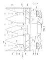
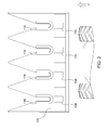
- FIGS. 1 and 2 show a self-propelled combine harvester 100 with a feederhouse 102 mounted at the front end of the combine 100 and extending forwardly therefrom. At the front end of the feederhouse 102, a corn picker 104 is also attached.
- the corn picker 104 includes a frame 106 that extends laterally and substantially transverse to the forward direction V.
- the frame 106 carries a transverse conveyor 108, which is a screw conveyor having a transversely extending cylinder 110 with conveyor coils 112 attached thereto.
- An engine (not shown, typically the internal combustion engine of the combine 100 via a driveline having a crosshead of the corn picker) is coupled to the cylinder 110 for transporting crop to the center of the cross conveyor 108.
- Laterally extending dogs 116 are attached to the central region of the cylinder 110 to transport the crop to the rear and into the feederhouse 102.
- the crop is then conveyed in the feederhouse 102 to the rear and into the combine harvester 100 for threshing, separating and cleaning.
- the corn picker 104 includes a number of row units 118 arranged side by side and fixed to a cross member 120.
- the cross member 120 extends laterally and substantially across the entire width of the corn picker transverse to the forward direction V.
- each row unit 118 is identical to each other.
- Each row unit 118 is in the form of a first, forwardly extending arm 122 on the left side of the row unit 118, and a second forwardly extending arm 124.
- the two arms 122, 124 unite in a gear housing at the rear of the row unit 118th
- the first forwardly extending arm 122 and the second forwardly extending arm 124 define therebetween a gap 128 configured to receive a series of stalk-like in-line plants 130 as the combine 100 moves across the field moved to harvest the plants 130.
- the row unit 118 is configured to strip corncob from the plant stems and separate the corn stalk near the bottom.
- the row units 118 leave a row of short corn stalks, also called stubble, extending substantially vertically from the bottom upwards.
- the stubble even if not individually very strong, can cause considerable damage to the tire 132 of the combine 100 over time.
- the corn picker 104 also includes stubble-breakers 134 which are attached to the corn picker 104, and particularly the cross-beam 120, and extend downwardly therefrom, breaking, buckling, lifting or tearing the stubble before the tires 132 reach the stubble.
- Breaking, kinking or at least partially tearing out the stubble significantly reduces damage to the tires.
- breaking, kinking or at least partially tearing out the stubble makes it easier to decompose the stubble in the soil. This decomposition enriches the soil.
- FIGS. 3 to 6 show a first embodiment of Stoppelknickers 134th Die
- FIGS. 7 to 10 show a second embodiment of Stoppelknickers 134 '.
- the Stoppelknicker 134 comprises a paddle 136 which is supported on a first spring 138 and a second spring 140.
- the paddle 136 is supported at a lower end of the first spring 138 and the second spring 140.
- the upper end of the first spring 138 and the second spring 140 is supported on a member 142, which in turn is supported on a bracket 154, which in turn is fixed to a lower portion of the cross member 120 by removable fasteners 155
- the element 142 is in the form of an elongate cylinder that extends laterally and substantially parallel to the cross member 120.
- the element 142 is supported at its two outer ends in openings of the console 154.
- the element can be pivoted in the openings about its longitudinal axis in a variety of different operating positions.
- the element 142 is held in these different operating positions by a pin 156 extending from a flange 158.
- the flange 158 is fixed to one end of the member 142, for example, by welding.
- the rotational position of the member 142 relative to the bracket 154 can be achieved by removing the pin, rotating the member 142 and Replace the pin 156 are changed into a corresponding hole 160 in the console.
- Several of these holes 160 are provided in the bracket 154 to support the member 142 in alternative rotational positions relative to the bracket 154.
- the first spring 138 includes a first helical spring portion 162 and the second spring 138 includes a second helical spring portion 164.
- the first spring portion 162 and the second spring portion 164 are wound around the member 142 so as to form the spring portions 162, 164 to support the element 142.
- a sufficient distance is provided between the first spring portion 162 and the second spring portion 164 to allow a lower end 166 of the first spring 138 and a lower end 168 of the second spring to deflect up and down when the stubble breaker 134 slides over the is pulled in the field upwards extending stubble.
- the first spring 138 has an upper end 170 which abuts a stop 172 on the element 142. As the member 142 is rotated relative to the bracket 154, the position of the stop 172 also changes. The stop 172 controls the position of the upper end 170. It therefore controls the bias and downward force of the spring 138 against the paddle 136 and thus the bias and downward force of the paddle 136 against the ground.
- the second spring 140 has an upper end 174 which abuts a stop 176 on the element 142. As the member 142 is rotated relative to the bracket 154, the position of the stop 176 also changes. The stop 176 controls the position of the upper end 174. It therefore controls the bias and downward force of the spring 140 against the paddle 136 and thus the bias and downward force of the paddle 136 against the ground.
- the upper ends 170 and 174 are secured together for simplicity.
- the two springs 138, 140 may be separate, individual components.
- the paddle 136 is slidably supported at the lower end 166 of the first spring 138 and at the lower end 168 of the second spring 140.
- a stop 178 is attached to the lower end 166 to prevent the paddle 136 from slipping off the lower end of the first spring 138.
- a stop 180 is attached to the lower end 168 to prevent the paddle 136 from slipping off the lower end of the second spring 140.
- a first biasing spring 182 (coupled to and between the paddle 136 and the first spring 138) is provided to bias the paddle 136 downwardly and toward a lower end of the lower end 166.
- a second biasing spring 184 (coupled to and between the paddle 136 and the second spring 140) is provided to bias the paddle 136 downwardly and toward a lower end of the lower end 168.
- Both the first biasing spring 182 and the second biasing spring 184 allow the paddle 136 to slide upwardly relative to the first spring 138 and the second spring 140. This upward sliding movement reduces the possibility of damaging the stubble cutter 134 as the combine 100 travels in reverse.
- the bottom acting against the underside 186 of the paddle will cause the paddle 136 to slide up along the lower end 166 and the lower end 168.
- the first biasing spring 182 and the second biasing spring 184 will push the paddle 136 down along the lower end 166 and the lower end 168.
- the stops 178 and 180 will prevent the paddle 136 from slipping off the lower ends 166 and 168.
- the paddle 136 rotates out of the in FIG. 5 shown position in the FIG. 6 shown position.
- This reversed movement of paddle 136 lifts upper end 170 (and upper end 174, not shown) off stop 172 (and stop 176, not shown).
- FIGS. 5 and 6 the construction and operation of the spring 138 is shown. Since the stubble breaker 134 is symmetrical about a vertical longitudinal plane passing through a lateral center of the stubble breaker 134, the construction and operation of the spring 140 are identical thereto.
- FIGS. 7 . 8th . 9 and 10 illustrate a second embodiment of a Stoppelknickers 134 ', in which the paddle 136' on a first spring 138 'and a second spring 140' is supported.
- a bracket 154 ' is secured to the cross member 120 by removable fasteners 155 and carries an element 142'.
- the member 142 ' is repositionable in a similar manner by removing a fastener 156' (shown here as threaded) from a flange 158 ', rotating the member 142', and re-attaching the removable fasteners 156 '.
- the first spring 138 'and the second spring 140' similarly have a first helical portion 162 'and a second helical portion 164', respectively, wound around the member 142 '.
- the first spring 138 'and the second spring 140' similarly have upper ends 170 'and 174' which abut against respective stoppers 172 'and 176'.
- the lower end 166 'of the spring 138' and the lower end 168 'of the spring 140' are formed as eyes, through which a pivot pin 188 and a pivot pin 189 extend.
- the pivot pins 188 and 189 are connected to the paddle 136 'in such a manner that the paddle 136' can pivot about an axis 190 opposite the lower end 166 'and the lower end 168', which is defined by the eyes at the lower ends 166 '. and 168 'is defined.
- the axis 190 is substantially horizontal and extends parallel to the longitudinal extent of the cross member 120th
- a stop 192 and stop 194 are secured to member 142 'to limit forward rotational movement of the upper ends of springs 138' and 140 ', respectively, with respect to cross member 120.
- the upper ends of the springs 138 'and 140' are free to pivot about the element 142 'from a first position, abutting the stoppers 172' and 176 'respectively, to a second position in which they abut Stops 192 and 194 abut when the direction of travel of the combine 100 changes from forward to reverse and the lower end 186 'is pulled forward through the bottom opposite the frame 106 of the corn picker 104.
- FIG. 9 12 illustrates the position of the paddle 136 'with respect to the springs 138' and 140 'as the combine 100 travels in its forward direction V and picks up crop.
- FIG. 10 shows the position of the paddle 136 'relative to the springs 138' and 140 'when the combine 100 is backing up.
- FIGS. 9 and 10 the construction and operation of the spring 138 'is shown. Since stubble-breaker 134 'is symmetrical about a vertical longitudinal plane passing through a lateral center of stubble-breaker 134', the structure and operation of spring 140 'are identical thereto.
- the stubble breaker 134 or 134 ' may be used not only on a corn picker 104 but also on a header for a forage harvester.
Landscapes
- Life Sciences & Earth Sciences (AREA)
- Environmental Sciences (AREA)
- Harvesting Machines For Specific Crops (AREA)
- Outside Dividers And Delivering Mechanisms For Harvesters (AREA)
- Soil Working Implements (AREA)
Abstract
Description
- Die Erfindung bezieht sich auf Maispflücker und insbesondere auf einen Stoppelknicker für einen Maispflücker.
- Mähdrescher ernten Mais mittels Maispflückern. Die Maispflücker sind an der Vorderseite des Mähdreschers befestigt und erstrecken sich in seitlicher Richtung quer zur Vorwärtsfahrtrichtung. Der Rahmen des Mähdreschers erstreckt sich ebenfalls seitlich und umfasst mehrere Reiheneinheiten. Jede Reiheneinheit ist konfiguriert, eine Reihe von Maispflanzen zu ernten.
- Wenn der Maispflücker den Maiskolben von der Pflanze trennt, lässt er den unteren Teil der Maisstängel (d.h. Maisstoppeln) aufwärts aus dem Boden ragend. Die Räder des Mähdreschers rollen in der Regel genau über eine Reihe der Maisstoppeln, was zu extremer Reifenabnutzung und vorzeitigem Austausch der Reifen aufgrund tiefer in den Reifen eingebrachter Nuten führt.
- Um dieses Problem zu lösen, sind so genannte Stoppelknicker hinter den Reiheneinheiten angeordnet, um die Stängel zu brechen, sie umzuknicken und sie teilweise aus dem Boden zu ziehen, bevor die Reifen des Mähdreschers sie erreichen.
- Die
US 8 171 707 A offenbart beispielsweise mehrere lange Walzen, die an jedem Ende durch schwenkbar angelenkte Arme am Rahmen des Maispflückers abgestützt sind. Diese Anordnung ist recht groß und schwer. - Die
US 2013/0061569 A1 offenbart als anderes Beispiel eine an einer Befestigungskonsole befestige Gleitplatte, wobei die Befestigungskonsole ihrerseits wiederum an einem einzigen, langgestreckten Haltestreifen angebracht ist. Diese Anordnung ist groß, schwer und benötigt einen beträchtlichen Bodenabstand. - Es besteht somit Bedarf an einem anderen Stoppelknicker, der ein geringeres Gewicht aufweist und weniger Raum einnimmt.
- Ein Stoppelknicker für einen Maispflücker umfasst eine Konsole, die konfiguriert ist, an der Unterseite eines eine Reiheneinheit abstützenden Rahmens eines Maispflückers befestigt zu werden, eine erste Feder, die ein oberes Ende umfasst, welches mit der Konsole gekoppelt ist, wobei die erste Feder auch ein unteres Ende umfasst, das sich von der Konsole nach unten erstreckt, eine zweite Feder, die ein oberes Ende umfasst, welches mit der Konsole gekoppelt ist, wobei die zweite Feder auch ein unteres Ende umfasst, das sich von der Konsole nach unten erstreckt; und ein Paddel, das im Wesentlichen flächig und am unteren Ende der ersten Feder und am unteren Ende der zweiten Feder abgestützt ist.
- Die erste Feder und die zweite Feder können jeweils einen wendelförmigen Abschnitt umfassen.
- An der Konsole kann ein Element abgestützt sein, um welches die wendelförmigen Abschnitte gewickelt sind. Das Element kann im Wesentlichen zylindrisch sein und zwei gegenüberliegende Enden aufweisen. Die Enden des Elements können an der Konsole (154, 154') abgestützt sein.
- Das Paddel kann eine erste Kante und eine gegenüberliegende, zweite Kante aufweisen, während das untere Ende der ersten Feder entlang der ersten Kante mit dem Paddel gekoppelt ist und das untere Ende der zweiten Feder entlang der zweiten Kante mit dem Paddel gekoppelt ist. Das Paddel kann am unteren Ende der ersten Feder und am unteren Ende der zweiten Feder gleitend abgestützt sein.
- Eine erste vorspannende Feder kann zwischen dem Paddel und der ersten Feder gekoppelt sein, um das Paddel gegenüber der ersten Feder nach unten vorzuspannen, und eine zweite vorspannende Feder kann zwischen dem Paddel und der zweiten Feder gekoppelt sein, um das Paddel gegenüber der zweiten Feder nach unten vorzuspannen.
- Das untere Ende der ersten Feder kann schwenkbar mit der ersten Kante gekoppelt sein, um das Paddel um eine sich insbesondere horizontal und quer zur Vorwärtsrichtung erstreckende Schwenkachse gegenüber dem unteren Ende der ersten Feder zu schwenken, während das untere Ende der zweiten Feder schwenkbar mit der zweiten Kante gekoppelt sein kann, um das Paddel um die Schwenkachse gegenüber dem unteren Ende der zweiten Feder zu schwenken.
- Eine Ausführungsform der Erfindung ist in den Zeichnungen gezeigt, von denen:
-
Figur 1 eine Draufsicht auf einen Mähdrescher mit einem Maispflücker mit einem Stoppelknicker zeigt, -
Figur 2 untere Ansicht des Maispflückers derFigur 1 zeigt, -
Figur 3 eine rückwärtige, perspektivische Ansicht einer ersten Ausführungsform eines Stoppelknickers derFiguren 1 und2 zeigt, -
Figur 4 eine frontseitige, perspektivische Ansicht des Stoppelknickers derFigur 3 zeigt, -
Figur 5 einen Querschnitt durch den Stoppelknicker derFiguren 3 und4 entlang der Linie 5-5 derFigur 4 zeigt, -
Figur 6 einen Querschnitt des Stoppelknickers derFiguren 3 und4 entlang der Linie 6-6 derFigur 4 zeigt, -
Figur 7 eine rückwärtige, perspektivische Ansicht einer ersten Ausführungsform eines Stoppelknickers derFiguren 1 und2 zeigt, -
Figur 8 eine frontseitige, perspektivische Ansicht des Stoppelknickers derFigur 7 zeigt, -
Figur 9 einen Querschnitt durch den Stoppelknicker derFiguren 7 und8 entlang der Linie 9-9 derFigur 4 zeigt, und -
Figur 10 einen Querschnitt des Stoppelknickers derFiguren 7 und8 entlang der Linie 10-10 derFigur 4 zeigt. - Die Ausdrücke "vordere", "nach vorn" etc. beziehen sich im Folgenden auf die Vorwärtsrichtung V des Mähdreschers und des Stoppelknickers beim Befahren eines Felds zur Ernte von stängelartigen Pflanzen. Analog beziehen sich die Ausdrücke "hinter", "nach hinten" oder dgl. auf die der Vorwärtsrichtung V entgegen gesetzte Richtung.
- Die
Figuren 1 und2 zeigen einen selbstfahrenden Mähdrescher 100 mit einem Schrägförderer 102, der am vorderen Ende des Mähdreschers 100 angebracht ist und sich von dort nach vorn erstreckt. Am vorderen Ende des Schrägförderers 102 ist auch ein Maispflücker 104 angebracht. - Der Maispflücker 104 umfasst einen Rahmen106, der sich seitlich und im Wesentlichen quer zur Vorwärtsrichtung V erstreckt. Der Rahmen 106 trägt einen Querförderer 108, bei dem es sich hier um einen Schneckenförderer mit einem sich quer erstreckenden Zylinder 110 mit daran befestigten Förderwendeln 112 handelt.
- Ein Motor (nicht gezeigt, in der Regel der Verbrennungsmotor des Mähdreschers 100 über einen Antriebsstrang mit einer Querwelle des Maispflückers) ist mit dem Zylinder 110 gekoppelt, um Erntegut zur Mitte des Querförderers 108 zu transportieren. Sich seitlich erstreckende Mitnehmer 116 sind an der mittleren Region des Zylinders 110 angebracht, um das Erntegut nach hinten und in den Schrägförderer 102 zu transportieren. Das Erntegut wird dann im Schrägförderer 102 nach hinten und in den Mähdrescher 100 zum Dreschen, Trennen und Reinigen gefördert.
- Der Maispflücker 104 umfasst eine Anzahl an Reiheneinheiten 118, die seitlich nebeneinander angeordnet und an einem Querträger 120 befestigt sind. Der Querträger 120 erstreckt sich seitlich und im Wesentlichen über die gesamte Breite des Maispflückers quer zur Vorwärtsrichtung V.
- Typischerweise sind alle Reiheneinheiten 118 untereinander identisch. Jede Reiheneinheit 118 ist in der Form eines ersten, sich nach vorn erstreckenden Armes 122 an der linken Seite der Reiheneinheit 118, und eines zweiten sich nach vorn erstreckenden Armes 124. Die beiden Arme 122, 124 vereinigen sich in einem Getriebegehäuse an der Rückseite der Reiheneinheit 118.
- Der erste, sich nach vorn erstreckende Arm 122 und der zweite, sich nach vorn erstreckende Arm 124 definieren eine Lücke 128 zwischen sich, die konfiguriert ist, eine Reihe an stängelartigen, in Reihen angebauten Pflanzen 130 aufzunehmen, wenn sich der Mähdrescher 100 über das Feld bewegt, um die Pflanzen 130 zu ernten. Die Reiheneinheit 118 ist konfiguriert, Maiskolben von den Pflanzenstängeln abzustreifen und den Maisstängel in der Nähe des Bodens abzutrennen.
- Wenn die Maisstängel abgetrennt sind, hinterlassen die Reiheneinheiten 118 eine Reihe kurzer Maisstängel, die auch als Stoppeln bezeichnet werden, die sich im Wesentlichen vertikal vom Boden nach oben erstrecken. Die Stoppeln können, auch wenn sie einzeln nicht sehr stark sind, über die Zeit den Reifen 132 des Mähdreschers 100 beträchtliche Schäden zufügen.
- Aus diesem Grunde umfasst der Maispflücker 104 auch Stoppelknicker 134, die am Maispflücker 104 und insbesondere am Querträger 120 befestigt sind und sich von dort nach unten erstrecken und die Stoppeln brechen, knicken, anheben oder herausreißen, bevor die Reifen 132 die Stoppeln erreichen.
- Auf diese Weise, z.B. durch Brechen, Knicken oder zumindest teilweise Herausreißen der Stoppeln wird die Beschädigung der Reifen beträchtlich vermindert. Außerdem wir durch das Brechen, Knicken oder zumindest teilweise Herausreißen der Stoppeln das Zersetzen der Stoppeln im Boden erleichtert. Dieses Zersetzen bereichert den Boden.
- Die
Figuren 3 bis 6 zeigen eine erste Ausführungsform des Stoppelknickers 134. DieFiguren 7 bis 10 zeigen eine zweite Ausführungsform des Stoppelknickers 134'. - Es wird nun auf die
Figuren 3 bis 6 verwiesen, gemäß denen der Stoppelknicker 134 ein Paddel 136 umfasst, das an einer ersten Feder 138 und einer zweiten Feder 140 abgestützt ist. Das Paddel 136 ist an einem unteren Ende der ersten Feder 138 und der zweiten Feder 140 abgestützt. Das obere Ende der ersten Feder 138 und der zweiten Feder 140 ist auf einem Element 142 abgestützt, welches wiederum an einer Konsole 154 abgestützt ist, die wiederum an einem unteren Abschnitt des Querträgers 120 durch abnehmbare Befestigungselemente 155 fixiert ist - Das Element 142 ist in der Form eines langgestreckten Zylinders, der sich seitlich und im Wesentlichen parallel zum Querträger 120 erstreckt. Das Element 142 ist an seinen beiden äußeren Enden in Öffnungen der Konsole 154 abgestützt. Das Element kann in den Öffnungen um seine Längsachse in eine Vielzahl unterschiedlicher Betriebspositionen geschwenkt werden.
- Das Element 142 wird in diesen unterschiedlichen Betriebspositionen durch einen Stift 156 gehalten, der sich von einem Flansch 158 erstreckt. Der Flansch 158 ist z.B. durch Schweißen an einem Ende des Elements 142 befestigt. Die Drehposition des Elements 142 gegenüber der Konsole 154 kann durch Entfernen des Stifts, Drehen des Elements 142 und Wiedereinsetzen des Stifts 156 in ein entsprechendes Loch 160 in der Konsole geändert werden. Mehrere dieser Löcher 160 sind in der Konsole 154 bereitgestellt, um das Element 142 in alternativen Drehpositionen gegenüber der Konsole 154 zu haltern.
- Die erste Feder 138 umfasst einen ersten, wendelförmigen Federabschnitt 162 und die zweite Feder 138 umfasst einen zweiten, wendelförmigen Federabschnitt 164. Der erste Federabschnitt 162 und der zweite Federabschnitt 164 sind um das Element 142 herum gewickelt, um auf diese Weise die Federabschnitte 162, 164 am Element 142 zu haltern. Es wird ein hinreichender Abstand zwischen dem ersten Federabschnitt 162 und dem zweiten Federabschnitt 164 bereitgestellt, um es einem unteren Ende 166 der ersten Feder 138 und einem unteren Ende 168 der zweiten Feder zu erlauben, nach unten und oben auszuweichen, wenn der Stoppelknicker 134 über die sich auf dem Feld nach oben erstreckenden Stoppeln gezogen wird.
- Die erste Feder 138 hat ein oberes Ende 170, das an einem Anschlag 172 am Element 142 anliegt. Wenn das Element 142 gegenüber der Konsole 154 gedreht wird, ändert sich auch die Position des Anschlags 172. Der Anschlag 172 kontrolliert die Position des oberen Endes 170. Er kontrolliert daher die Vorspannung und nach unten gerichtete Kraft der Feder 138 gegen das Paddel 136 und somit die Vorspannung und nach unten gerichtete Kraft des Paddels 136 gegen den Boden.
- Die zweite Feder 140 hat ein oberes Ende 174, das an einem Anschlag 176 am Element 142 anliegt. Wenn das Element 142 gegenüber der Konsole 154 gedreht wird, ändert sich auch die Position des Anschlags 176. Der Anschlag 176 kontrolliert die Position des oberen Endes 174. Er kontrolliert daher die Vorspannung und nach unten gerichtete Kraft der Feder 140 gegen das Paddel 136 und somit die Vorspannung und nach unten gerichtete Kraft des Paddels 136 gegen den Boden.
- Bei der hier gezeigten Anordnung sind die oberen Enden 170 und 174 zur Vereinfachung aneinander befestigt. Bei einer anderen Anordnung können die beiden Federn 138, 140 jedoch getrennte, einzelne Komponenten sein.
- Das Paddel 136 ist verschiebbar am unteren Ende 166 der ersten Feder 138 und am unteren Ende 168 der zweiten Feder 140 abgestützt. Ein Anschlag 178 ist am unteren Ende 166 befestigt, um das Paddel 136 daran zu hindern, vom unteren Ende der ersten Feder 138 abzurutschen. Ein Anschlag 180 ist am unteren Ende 168 befestigt, um das Paddel 136 daran zu hindern, vom unteren Ende der zweiten Feder 140abzurutschen.
- Eine erste vorspannende Feder 182 (gekoppelt mit und zwischen dem Paddel 136 und der ersten Feder 138) ist bereitgestellt, um das Paddel 136 nach unten und in Richtung auf ein unteres Ende des unteren Endes 166 vorzuspannen. Eine zweite vorspannende Feder 184 (gekoppelt mit und zwischen dem Paddel 136 und der zweiten Feder 140) ist bereitgestellt, um das Paddel 136 nach unten und in Richtung auf ein unteres Ende des unteren Endes 168 vorzuspannen.
- Sowohl die erste vorspannende Feder 182 als auch die zweite vorspannende Feder 184 erlauben es dem Paddel 136, gegenüber der ersten Feder 138 und der zweiten Feder 140 nach oben zu gleiten. Diese nach oben gerichtete Gleitbewegung vermindert die Möglichkeit einer Beschädigung des Stoppelknickers 134, wenn der Mähdrescher 100 rückwärts fährt.
- Wenn der Mähdrescher 100 rückwärts fährt wird der gegen die Unterseite 186 des Paddels wirkende Boden bewirken, dass das Paddel 136 entlang des unteren Endes 166 und des unteren Endes 168 nach oben gleitet. Wenn der Mähdrescher 100 wieder in eine Vorwärtsrichtung fährt, werden die erste vorspannende Feder 182 und die zweite vorspannende Feder 184 das Paddel 136 entlang des unteren Endes 166 und des unteren Endes 168 nach unten drücken. Die Anschläge 178 und 180 werden verhindern, dass das Paddel 136 von den unteren Enden 166 und 168 abrutscht.
- Wenn der Mähdrescher 100 rückwärts fährt, dreht sich das Paddel 136 aus der in
Figur 5 gezeigten Position in die inFigur 6 gezeigte Position. Diese reversierte Bewegung des Paddels 136 hebt das obere Ende 170 (und das nicht gezeigte obere Ende 174) vom Anschlag 172 (und dem nicht gezeigten Anschlag 176) ab. Dies ermöglicht es der ersten, wendelförmigen Federabschnitt 162 (und dem nicht gezeigten, jedoch identischen zweiten, wendelförmigen Federabschnitt 164) in der umgekehrten Richtung frei zu drehen und schlaff zu bleiben und nicht in der umgekehrten Richtung gespannt zu werden. Dieses vermindert den Betrag des Eindringens und Grabens der Unterseite 186 des Paddels 136 in den Boden, wenn es in Rückwärtsrichtung gezogen wird (vgl.Figur 6 ). - In den
Figuren 5 und 6 wird der Aufbau und Betrieb der Feder 138 gezeigt. Da der Stoppelknicker 134 zur einer vertikalen Längsebene symmetrisch ist, die durch einen seitlichen Mittelpunkt des Stoppelknickers 134 verläuft, sind der Aufbau und Betrieb der Feder 140 identisch dazu. - Die
Figuren 7 ,8 ,9 und 10 illustrieren eine zweite Ausführungsform eines Stoppelknickers 134', bei welcher das Paddel 136' an einer ersten Feder 138' und einer zweiten Feder 140' abgestützt ist. Auf derselben Weise wie in derFiguren 1 bis 6 ist eine Konsole 154' durch abnehmbare Befestigungselemente 155 am Querträger 120 befestigt und trägt ein Element 142'. Das Element 142' ist auf ähnliche Weise durch Entfernung eines Befestigers 156' (der hier als mit Gewinde versehen gezeigt ist) von einem Flansch 158', drehen des Elements 142' und Wiederanbringen der abnehmbaren Befestiger 156' repositionierbar. Die erste Feder 138' und die zweite Feder 140' haben in ähnlicher Weise einen ersten wendelförmigen Abschnitt 162' bzw. einen zweiten wendelförmigen Abschnitt 164', die um das Element 142' gewickelt sind. Die erste Feder 138' und die zweite Feder 140' haben in ähnlicher Weise obere Enden 170' und 174', die an entsprechenden Anschlägen 172' und 176' anliegen. - Das untere Ende 166' der Feder 138' und das untere Ende 168' der Feder 140' sind als Augen geformt, durch welche sich ein Schwenkstift 188 bzw. ein Schwenkstift 189 erstrecken. Die Schwenkstifte 188 und 189 sind in der Weise mit dem Paddel 136' verbunden, dass das Paddel 136' gegenüber dem unteren Ende 166' und dem unteren Ende 168' um eine Achse 190 schwenken kann, welche durch die Augen an den unteren Enden 166' und 168' definiert ist. Die Achse 190 ist im Wesentlichen horizontal und erstreckt sich parallel zur Längserstreckung des Querträgers 120.
- Ein Anschlag 192 und ein Anschlag 194 sind am Element 142' befestigt, um die nach vorn gerichtete Drehbewegung der oberen Enden der Federn 138' bzw. 140' gegenüber dem Querträger 120 zu begrenzen. Auf diese Weise können die oberen Enden der Federn 138' und 140' frei um das Element 142' von einer ersten Position, in der sei an den Anschlägen 172' bzw. 176' anliegen, in eine zweite Position verschwenken, in der sie an den Anschlägen 192 bzw. 194 anliegen, wenn sich die Fahrtrichtung des Mähdreschers 100 von vorwärts auf rückwärts ändert und das untere Ende 186' durch den Boden gegenüber dem Rahmen 106 des Maispflückers 104 nach vorn gezogen wird.
- Gleichzeitig (d.h. wenn die Fahrtrichtung umgekehrt wird) ändert sich auch die Position des Paddels 136' gegenüber der Feder 138' und der Feder 140'.
Figur 9 stellt die Position des Paddels 136' gegenüber den Federn 138' und 140' dar, wenn der Mähdrescher 100 in seiner Vorwärtsrichtung V fährt und Erntegut aufnimmt. DieFigur 10 zeigt die Position des Paddels 136' gegenüber den Federn 138' und 140' wenn der Mähdrescher 100 rückwärts fährt. - In der
Figur 9 ist das Paddel 136' gegenüber der Feder 138' nach hinten geschwenkt worden, bis ein im Paddel 136' geformter Anschlag 196 am unteren Ende der Feder 138' anliegt. Dieses verhindert eine weitere Rückschwenkbewegung des Paddels 136' gegenüber dem unteren Ende der Feder 138'. Jede weitere Rückwärtsbewegung des Paddels 136' führt dazu, dass die Feder 138' nach hinten ausfedert. In dieser Position liegt das obere Ende 170' der Feder 138' am Anschlag 172' an und hindert sie daran, gegenüber dem Element 142' weiter zu rotieren. - In der
Figur 10 ist das Paddel 136' gegenüber der Feder 138' um die Schwenkachse 190 nach vorn und vom Anschlag 196 fort verschwenkt. Dieses setzt den Niederdruck der Feder 138' aus und erlaubt es dem unteren Ende 186' des Paddels 136' leicht gegen den Boden zu drücken. Gleichzeitig verschwenkt die Feder 138' nach vorn, bis ihr oberes Ende 170' am Anschlag 192 anliegt, was ein weiteres Verschwenken der Feder 138' in Vorwärtsrichtung gegenüber dem Querträger 142' verhindert. - In den
Figuren 9 und 10 wird der Aufbau und Betrieb der Feder 138' gezeigt. Da der Stoppelknicker 134' zur einer vertikalen Längsebene symmetrisch ist, die durch einen seitlichen Mittelpunkt des Stoppelknickers 134' verläuft, sind der Aufbau und Betrieb der Feder 140' identisch dazu. - Die Figuren und Erläuterungen zeigen zwei Ausführungsformen der Erfindung. Es sei noch angemerkt, dass der Stoppelknicker 134 oder 134' nicht nur an einem Maispflücker 104, sondern auch an einem Mähvorsatz für einen Feldhäcksler verwendet werden kann.
Claims (10)
- Stoppelknicker (134, 134') für einen Maispflücker (104), mit:einer Konsole (154, 154'), die konfiguriert ist, an der Unterseite eines eine Reiheneinheit (118) abstützenden Rahmens (106) eines Maispflückers (104) befestigt zu werden;einer ersten Feder (138, 138'), die ein oberes Ende umfasst, welches mit der Konsole (154, 154') gekoppelt ist, wobei die erste Feder (138, 138') auch ein unteres Ende (166, 166') umfasst, das sich von der Konsole (154, 154') nach unten erstreckt;einer zweiten Feder (140, 140'), die ein oberes Ende umfasst, welches mit der Konsole (154, 154') gekoppelt ist, wobei die zweite Feder (140, 140') auch ein unteres Ende (168, 168') umfasst, das sich von der Konsole (154, 154') nach unten erstreckt; undeinem Paddel (136, 136'), das im Wesentlichen flächig und am unteren Ende (166, 166') der ersten Feder (138, 138') und am unteren Ende (168, 168') der zweiten Feder (140, 140') abgestützt ist.
- Stoppelknicker (134, 134') nach Anspruch 1, wobei die erste Feder (138, 138') und die zweite Feder (140, 140') einen wendelförmigen Abschnitt (162, 162', 164, 164') umfassen.
- Stoppelknicker (134, 134') nach Anspruch 2, mit einem an der Konsole (154, 154') abgestützten Element (142, 142'), um welches die wendelförmigen Abschnitte (162, 162', 164, 164') gewickelt sind.
- Stoppelknicker (134, 134') nach Anspruch 3, wobei das Element (142, 142') im Wesentlichen zylindrisch ist und zwei gegenüberliegende Enden aufweist.
- Stoppelknicker (134, 134') nach Anspruch 4, wobei die Enden des Elements (142, 142') an der Konsole (154, 154') abgestützt sind.
- Stoppelknicker (134, 134') nach Anspruch 1, wobei das Paddel (136, 136') eine erste Kante und eine gegenüberliegende, zweite Kante aufweist, und wobei das untere Ende (166, 166') der ersten Feder (138, 138') entlang der ersten Kante mit dem Paddel (136, 136') gekoppelt ist und das untere Ende der zweiten Feder (140, 140') entlang der zweiten Kante mit dem Paddel (136, 136') gekoppelt ist.
- Stoppelknicker (134, 134') nach Anspruch 6, wobei das Paddel (136, 136') am unteren Ende (166, 166') der ersten Feder (138, 138') und am unteren Ende (168, 168') der zweiten Feder (140, 140') gleitend abgestützt ist.
- Stoppelknicker (134, 134') nach Anspruch 7, mit einer ersten vorspannenden Feder (182), die zwischen dem Paddel (136) und der ersten Feder (138) gekoppelt ist, um das Paddel (136) gegenüber der ersten Feder (138) nach unten vorzuspannen, und mit einer zweiten vorspannenden Feder (184), die zwischen dem Paddel (136) und der zweiten Feder (140) gekoppelt ist, um das Paddel (136) gegenüber der zweiten Feder (140) nach unten vorzuspannen.
- Stoppelknicker (134') nach Anspruch 6, wobei das untere Ende (166') der ersten Feder (138') schwenkbar mit der ersten Kante gekoppelt ist, um das Paddel (136') um eine sich insbesondere horizontal und quer zur Vorwärtsrichtung (V) erstreckende Schwenkachse (190) gegenüber dem unteren Ende (166') der ersten Feder (138') zu schwenken, und wobei das untere Ende (168') der zweiten Feder (140') schwenkbar mit der zweiten Kante gekoppelt ist, um das Paddel (136') um die Schwenkachse (190) gegenüber dem unteren Ende (168') der zweiten Feder (140') zu schwenken.
- Maispflücker (104) mit einem Rahmen (106), einer Mehrzahl an am Rahmen (106) befestigten Reiheneinheiten (118) und wenigstens einem am Rahmen (106) befestigten Stoppelknicker (134') nach Anspruch 1.
Applications Claiming Priority (1)
| Application Number | Priority Date | Filing Date | Title |
|---|---|---|---|
| US14/196,386 US20150250098A1 (en) | 2014-03-04 | 2014-03-04 | Stalk Breaker for a Corn Head |
Publications (2)
| Publication Number | Publication Date |
|---|---|
| EP2915421A1 true EP2915421A1 (de) | 2015-09-09 |
| EP2915421B1 EP2915421B1 (de) | 2017-05-10 |
Family
ID=52477624
Family Applications (1)
| Application Number | Title | Priority Date | Filing Date |
|---|---|---|---|
| EP15154972.2A Active EP2915421B1 (de) | 2014-03-04 | 2015-02-13 | Stoppelknicker für einen maispflücker |
Country Status (3)
| Country | Link |
|---|---|
| US (1) | US20150250098A1 (de) |
| EP (1) | EP2915421B1 (de) |
| BR (1) | BR102015004542B1 (de) |
Cited By (1)
| Publication number | Priority date | Publication date | Assignee | Title |
|---|---|---|---|---|
| EP4335279A1 (de) * | 2022-08-31 | 2024-03-13 | Macdon Industries Ltd. | Stoppelknicker mit selbstrückstellender bruchschutzfunktion |
Families Citing this family (8)
| Publication number | Priority date | Publication date | Assignee | Title |
|---|---|---|---|---|
| US10231379B2 (en) * | 2014-12-30 | 2019-03-19 | Agco Corporation | Easy mount stalk stomper |
| CA2929838C (en) * | 2015-06-17 | 2021-06-01 | Dynamic Ditchers Inc. | Soil spreading scraper device including deflecting paddles |
| US11172612B2 (en) | 2018-02-20 | 2021-11-16 | DK AG Solutions LLC | Agricultural machine attachment for corn stalk flattening |
| CN108142124A (zh) * | 2018-02-26 | 2018-06-12 | 浙江开创智库科技有限公司 | 一种玉米秸秆饲料粉碎机用进料机器人 |
| US10945371B2 (en) | 2018-06-05 | 2021-03-16 | Cnh Industrial America Llc | Adjustable stalk stomper/chopper curtain assembly |
| US10550544B1 (en) | 2019-04-17 | 2020-02-04 | Edwin A. Erickson | Spring loaded feeding device |
| US10544563B1 (en) | 2019-04-17 | 2020-01-28 | Edwin A. Erickson | Spring loaded feeding device |
| US11647693B2 (en) | 2019-11-14 | 2023-05-16 | Cnh Industrial America Llc | Stomping shoe assembly for an agricultural harvester header |
Citations (5)
| Publication number | Priority date | Publication date | Assignee | Title |
|---|---|---|---|---|
| US8171707B2 (en) | 2010-01-25 | 2012-05-08 | Kitchel Enterprises, Llc | Corn stalk rollers |
| EP2520151A1 (de) * | 2011-05-02 | 2012-11-07 | Deere & Company | Sensor für ein System zur Steuerung eines Vorsatzgerätes |
| US20130019581A1 (en) * | 2011-07-22 | 2013-01-24 | Lankota Group, Inc. | Stem deflector |
| US20130020101A1 (en) * | 2011-07-19 | 2013-01-24 | Shoup Kenneth E | Quick connect/disconnect coupling for a stalk stomper |
| US20130061569A1 (en) | 2010-11-03 | 2013-03-14 | Dean J. McClenathen | Device for flattening corn stalk stubbles |
Family Cites Families (23)
| Publication number | Priority date | Publication date | Assignee | Title |
|---|---|---|---|---|
| US1680218A (en) * | 1927-03-26 | 1928-08-07 | William H Keune | Stalk breaker |
| US1851379A (en) * | 1929-09-16 | 1932-03-29 | Worthley Herbert | Stubble burner |
| US2322076A (en) * | 1941-04-30 | 1943-06-15 | C C Pickens | Stalk cutter |
| US3163974A (en) * | 1962-10-05 | 1965-01-05 | Carl L Mack | Automatic height control for combine header |
| US3286448A (en) * | 1964-01-21 | 1966-11-22 | Roper Wright Mfg Co Inc | Automatic header control apparatus |
| US3238709A (en) * | 1964-10-05 | 1966-03-08 | Carl D Williams | Float and adjusting mechanism |
| US3747311A (en) * | 1971-10-13 | 1973-07-24 | Clayson Nv | Mechanism for the automatic adjustment of the header of harvesting machines |
| US3808783A (en) * | 1972-06-07 | 1974-05-07 | Deere & Co | Soybean harvesting header |
| US3925971A (en) * | 1974-03-15 | 1975-12-16 | Hesston Corp | Gauging apparatus for implement head |
| US4144698A (en) * | 1977-01-10 | 1979-03-20 | Lloyd Younger | Stubble flattener attachment |
| US4211057A (en) * | 1978-03-20 | 1980-07-08 | Massey-Ferguson Industries Limited | Combine harvester automatic table height control |
| US4835954A (en) * | 1988-02-03 | 1989-06-06 | Deutz-Allis Corporation | Combine header with skid plates |
| US6539697B2 (en) * | 2001-02-22 | 2003-04-01 | Carl A. Burk | Apparatus and method for knocking down and crushing farm crop residue |
| DE20116343U1 (de) * | 2001-10-05 | 2001-12-20 | FAE ITALIA S.r.l., Fonto, Trento | Zerkleinerungsmaschine |
| US7156186B2 (en) * | 2002-02-02 | 2007-01-02 | Cnh America Llc | Strip-till conditioning rotary reel |
| US8348292B2 (en) * | 2010-04-26 | 2013-01-08 | Eagle Wing Llc | Methods and apparatus for the protection of vehicle tires |
| US8146335B2 (en) * | 2010-05-07 | 2012-04-03 | Deere & Company | Sensor for a header height control system |
| US8567167B2 (en) * | 2011-07-19 | 2013-10-29 | Kenneth E. Shoup | Quick connect/disconnect coupling for a stalk stomper |
| US8858110B2 (en) * | 2011-07-19 | 2014-10-14 | Kenneth E. Shoup | Quick connect/disconnect coupling for a stalk stomper |
| US20130174529A1 (en) * | 2012-01-11 | 2013-07-11 | Lankota Group, Inc. | Stem Deflector Mount |
| US20130177348A1 (en) * | 2012-01-11 | 2013-07-11 | Lankota Group, Inc. | Stem deflector mount |
| US8979106B2 (en) * | 2012-11-12 | 2015-03-17 | Shoup Manufacturing Company | Tire protection mount |
| US20150096773A1 (en) * | 2013-10-03 | 2015-04-09 | Ricky Alan Miller | Stalk stomper |
-
2014
- 2014-03-04 US US14/196,386 patent/US20150250098A1/en not_active Abandoned
-
2015
- 2015-02-13 EP EP15154972.2A patent/EP2915421B1/de active Active
- 2015-03-02 BR BR102015004542-5A patent/BR102015004542B1/pt active IP Right Grant
Patent Citations (5)
| Publication number | Priority date | Publication date | Assignee | Title |
|---|---|---|---|---|
| US8171707B2 (en) | 2010-01-25 | 2012-05-08 | Kitchel Enterprises, Llc | Corn stalk rollers |
| US20130061569A1 (en) | 2010-11-03 | 2013-03-14 | Dean J. McClenathen | Device for flattening corn stalk stubbles |
| EP2520151A1 (de) * | 2011-05-02 | 2012-11-07 | Deere & Company | Sensor für ein System zur Steuerung eines Vorsatzgerätes |
| US20130020101A1 (en) * | 2011-07-19 | 2013-01-24 | Shoup Kenneth E | Quick connect/disconnect coupling for a stalk stomper |
| US20130019581A1 (en) * | 2011-07-22 | 2013-01-24 | Lankota Group, Inc. | Stem deflector |
Cited By (1)
| Publication number | Priority date | Publication date | Assignee | Title |
|---|---|---|---|---|
| EP4335279A1 (de) * | 2022-08-31 | 2024-03-13 | Macdon Industries Ltd. | Stoppelknicker mit selbstrückstellender bruchschutzfunktion |
Also Published As
| Publication number | Publication date |
|---|---|
| BR102015004542A2 (pt) | 2016-07-12 |
| BR102015004542B1 (pt) | 2021-01-05 |
| US20150250098A1 (en) | 2015-09-10 |
| EP2915421B1 (de) | 2017-05-10 |
Similar Documents
| Publication | Publication Date | Title |
|---|---|---|
| EP2915421B1 (de) | Stoppelknicker für einen maispflücker | |
| DE102011081403B4 (de) | Flexibles Schneidwerk mit Querfördergurten und Schwenkgeometrie | |
| DE102011081400B4 (de) | Schneidwerk mit Querfördergurten und Sollbruchstelle | |
| DE60219756T2 (de) | Gerät zur Behandlung von Erntegut | |
| EP1287732B1 (de) | Erntevorsatz | |
| DE102013204977B4 (de) | Schneidwerk mit Querförderbändern und um die Hochachse schwenkbaren Förderwalzen | |
| DE102012108835A1 (de) | Schneidwerk | |
| EP1010363B1 (de) | Maschine zum Mähen und Häckseln von Mais und dgl. stengelartigem Erntegut | |
| EP2067397B1 (de) | Erntevorsatz für landwirtschaftliche Erntemaschinen zum Aufnehmen und Weiterfördern von Halmfrüchten | |
| DD226747A5 (de) | Reihenabtastvorrichtung fuer eine erntemaschine | |
| EP1688030A1 (de) | Teilerspitze für einen landwirtschaftlichen Erntevorsatz | |
| DE10242796A1 (de) | Erntegerät zur Ernte stängelartiger Pflanzen | |
| EP3007540B1 (de) | Pflückvorrichtung | |
| DE102007007985B4 (de) | Schneidwerk zum Abschneiden von stängeligem Schnittgut | |
| DE102021110799A1 (de) | Sperrsystem für einen erntevorsatz | |
| EP0503468B1 (de) | Schneidwerk für Mähdrescher | |
| BE1023463B1 (de) | Erntevorsatz mit seitlicher Abdeckung | |
| WO2014198599A1 (de) | Erntemaschine zum mähen stängeliger pflanzen | |
| EP1306003A1 (de) | Ballenpresse für landwirtschaftliches Erntegut | |
| DE10327176B4 (de) | Pflückeinrichtung | |
| EP1199921A1 (de) | Erntegerät | |
| DE2345494A1 (de) | Sammelblech-anordnung bei einem kolbenpflueck-vorsatzgeraet | |
| DE102004024232B4 (de) | Schneidwerk mit Fördergutzusammenbauten | |
| DE2610600A1 (de) | Maehdrescher der axialfluss-bauart | |
| DE202015003357U1 (de) | Schneidwerk für eine Erntemaschine |
Legal Events
| Date | Code | Title | Description |
|---|---|---|---|
| PUAI | Public reference made under article 153(3) epc to a published international application that has entered the european phase |
Free format text: ORIGINAL CODE: 0009012 |
|
| AK | Designated contracting states |
Kind code of ref document: A1 Designated state(s): AL AT BE BG CH CY CZ DE DK EE ES FI FR GB GR HR HU IE IS IT LI LT LU LV MC MK MT NL NO PL PT RO RS SE SI SK SM TR |
|
| AX | Request for extension of the european patent |
Extension state: BA ME |
|
| 17P | Request for examination filed |
Effective date: 20160309 |
|
| RBV | Designated contracting states (corrected) |
Designated state(s): AL AT BE BG CH CY CZ DE DK EE ES FI FR GB GR HR HU IE IS IT LI LT LU LV MC MK MT NL NO PL PT RO RS SE SI SK SM TR |
|
| GRAP | Despatch of communication of intention to grant a patent |
Free format text: ORIGINAL CODE: EPIDOSNIGR1 |
|
| RIC1 | Information provided on ipc code assigned before grant |
Ipc: A01D 34/835 20060101AFI20161115BHEP |
|
| INTG | Intention to grant announced |
Effective date: 20161209 |
|
| GRAS | Grant fee paid |
Free format text: ORIGINAL CODE: EPIDOSNIGR3 |
|
| GRAA | (expected) grant |
Free format text: ORIGINAL CODE: 0009210 |
|
| AK | Designated contracting states |
Kind code of ref document: B1 Designated state(s): AL AT BE BG CH CY CZ DE DK EE ES FI FR GB GR HR HU IE IS IT LI LT LU LV MC MK MT NL NO PL PT RO RS SE SI SK SM TR |
|
| REG | Reference to a national code |
Ref country code: GB Ref legal event code: FG4D Free format text: NOT ENGLISH |
|
| REG | Reference to a national code |
Ref country code: AT Ref legal event code: REF Ref document number: 891304 Country of ref document: AT Kind code of ref document: T Effective date: 20170515 Ref country code: CH Ref legal event code: EP |
|
| REG | Reference to a national code |
Ref country code: IE Ref legal event code: FG4D Free format text: LANGUAGE OF EP DOCUMENT: GERMAN |
|
| REG | Reference to a national code |
Ref country code: DE Ref legal event code: R096 Ref document number: 502015000994 Country of ref document: DE |
|
| REG | Reference to a national code |
Ref country code: NL Ref legal event code: MP Effective date: 20170510 |
|
| REG | Reference to a national code |
Ref country code: LT Ref legal event code: MG4D |
|
| PG25 | Lapsed in a contracting state [announced via postgrant information from national office to epo] |
Ref country code: HR Free format text: LAPSE BECAUSE OF FAILURE TO SUBMIT A TRANSLATION OF THE DESCRIPTION OR TO PAY THE FEE WITHIN THE PRESCRIBED TIME-LIMIT Effective date: 20170510 Ref country code: NO Free format text: LAPSE BECAUSE OF FAILURE TO SUBMIT A TRANSLATION OF THE DESCRIPTION OR TO PAY THE FEE WITHIN THE PRESCRIBED TIME-LIMIT Effective date: 20170810 Ref country code: LT Free format text: LAPSE BECAUSE OF FAILURE TO SUBMIT A TRANSLATION OF THE DESCRIPTION OR TO PAY THE FEE WITHIN THE PRESCRIBED TIME-LIMIT Effective date: 20170510 Ref country code: ES Free format text: LAPSE BECAUSE OF FAILURE TO SUBMIT A TRANSLATION OF THE DESCRIPTION OR TO PAY THE FEE WITHIN THE PRESCRIBED TIME-LIMIT Effective date: 20170510 Ref country code: FI Free format text: LAPSE BECAUSE OF FAILURE TO SUBMIT A TRANSLATION OF THE DESCRIPTION OR TO PAY THE FEE WITHIN THE PRESCRIBED TIME-LIMIT Effective date: 20170510 Ref country code: GR Free format text: LAPSE BECAUSE OF FAILURE TO SUBMIT A TRANSLATION OF THE DESCRIPTION OR TO PAY THE FEE WITHIN THE PRESCRIBED TIME-LIMIT Effective date: 20170811 |
|
| PG25 | Lapsed in a contracting state [announced via postgrant information from national office to epo] |
Ref country code: RS Free format text: LAPSE BECAUSE OF FAILURE TO SUBMIT A TRANSLATION OF THE DESCRIPTION OR TO PAY THE FEE WITHIN THE PRESCRIBED TIME-LIMIT Effective date: 20170510 Ref country code: LV Free format text: LAPSE BECAUSE OF FAILURE TO SUBMIT A TRANSLATION OF THE DESCRIPTION OR TO PAY THE FEE WITHIN THE PRESCRIBED TIME-LIMIT Effective date: 20170510 Ref country code: IS Free format text: LAPSE BECAUSE OF FAILURE TO SUBMIT A TRANSLATION OF THE DESCRIPTION OR TO PAY THE FEE WITHIN THE PRESCRIBED TIME-LIMIT Effective date: 20170910 Ref country code: BG Free format text: LAPSE BECAUSE OF FAILURE TO SUBMIT A TRANSLATION OF THE DESCRIPTION OR TO PAY THE FEE WITHIN THE PRESCRIBED TIME-LIMIT Effective date: 20170810 Ref country code: NL Free format text: LAPSE BECAUSE OF FAILURE TO SUBMIT A TRANSLATION OF THE DESCRIPTION OR TO PAY THE FEE WITHIN THE PRESCRIBED TIME-LIMIT Effective date: 20170510 Ref country code: PL Free format text: LAPSE BECAUSE OF FAILURE TO SUBMIT A TRANSLATION OF THE DESCRIPTION OR TO PAY THE FEE WITHIN THE PRESCRIBED TIME-LIMIT Effective date: 20170510 Ref country code: SE Free format text: LAPSE BECAUSE OF FAILURE TO SUBMIT A TRANSLATION OF THE DESCRIPTION OR TO PAY THE FEE WITHIN THE PRESCRIBED TIME-LIMIT Effective date: 20170510 |
|
| PG25 | Lapsed in a contracting state [announced via postgrant information from national office to epo] |
Ref country code: RO Free format text: LAPSE BECAUSE OF FAILURE TO SUBMIT A TRANSLATION OF THE DESCRIPTION OR TO PAY THE FEE WITHIN THE PRESCRIBED TIME-LIMIT Effective date: 20170510 Ref country code: SK Free format text: LAPSE BECAUSE OF FAILURE TO SUBMIT A TRANSLATION OF THE DESCRIPTION OR TO PAY THE FEE WITHIN THE PRESCRIBED TIME-LIMIT Effective date: 20170510 Ref country code: EE Free format text: LAPSE BECAUSE OF FAILURE TO SUBMIT A TRANSLATION OF THE DESCRIPTION OR TO PAY THE FEE WITHIN THE PRESCRIBED TIME-LIMIT Effective date: 20170510 Ref country code: DK Free format text: LAPSE BECAUSE OF FAILURE TO SUBMIT A TRANSLATION OF THE DESCRIPTION OR TO PAY THE FEE WITHIN THE PRESCRIBED TIME-LIMIT Effective date: 20170510 Ref country code: CZ Free format text: LAPSE BECAUSE OF FAILURE TO SUBMIT A TRANSLATION OF THE DESCRIPTION OR TO PAY THE FEE WITHIN THE PRESCRIBED TIME-LIMIT Effective date: 20170510 |
|
| REG | Reference to a national code |
Ref country code: DE Ref legal event code: R097 Ref document number: 502015000994 Country of ref document: DE |
|
| REG | Reference to a national code |
Ref country code: FR Ref legal event code: PLFP Year of fee payment: 4 |
|
| PG25 | Lapsed in a contracting state [announced via postgrant information from national office to epo] |
Ref country code: SM Free format text: LAPSE BECAUSE OF FAILURE TO SUBMIT A TRANSLATION OF THE DESCRIPTION OR TO PAY THE FEE WITHIN THE PRESCRIBED TIME-LIMIT Effective date: 20170510 |
|
| PLBE | No opposition filed within time limit |
Free format text: ORIGINAL CODE: 0009261 |
|
| STAA | Information on the status of an ep patent application or granted ep patent |
Free format text: STATUS: NO OPPOSITION FILED WITHIN TIME LIMIT |
|
| 26N | No opposition filed |
Effective date: 20180213 |
|
| PG25 | Lapsed in a contracting state [announced via postgrant information from national office to epo] |
Ref country code: SI Free format text: LAPSE BECAUSE OF FAILURE TO SUBMIT A TRANSLATION OF THE DESCRIPTION OR TO PAY THE FEE WITHIN THE PRESCRIBED TIME-LIMIT Effective date: 20170510 |
|
| REG | Reference to a national code |
Ref country code: CH Ref legal event code: PL |
|
| PG25 | Lapsed in a contracting state [announced via postgrant information from national office to epo] |
Ref country code: MC Free format text: LAPSE BECAUSE OF FAILURE TO SUBMIT A TRANSLATION OF THE DESCRIPTION OR TO PAY THE FEE WITHIN THE PRESCRIBED TIME-LIMIT Effective date: 20170510 Ref country code: MT Free format text: LAPSE BECAUSE OF FAILURE TO SUBMIT A TRANSLATION OF THE DESCRIPTION OR TO PAY THE FEE WITHIN THE PRESCRIBED TIME-LIMIT Effective date: 20170510 |
|
| REG | Reference to a national code |
Ref country code: BE Ref legal event code: MM Effective date: 20180228 |
|
| PG25 | Lapsed in a contracting state [announced via postgrant information from national office to epo] |
Ref country code: LU Free format text: LAPSE BECAUSE OF NON-PAYMENT OF DUE FEES Effective date: 20180213 Ref country code: LI Free format text: LAPSE BECAUSE OF NON-PAYMENT OF DUE FEES Effective date: 20180228 Ref country code: CH Free format text: LAPSE BECAUSE OF NON-PAYMENT OF DUE FEES Effective date: 20180228 |
|
| REG | Reference to a national code |
Ref country code: IE Ref legal event code: MM4A |
|
| PG25 | Lapsed in a contracting state [announced via postgrant information from national office to epo] |
Ref country code: IE Free format text: LAPSE BECAUSE OF NON-PAYMENT OF DUE FEES Effective date: 20180213 |
|
| PG25 | Lapsed in a contracting state [announced via postgrant information from national office to epo] |
Ref country code: BE Free format text: LAPSE BECAUSE OF NON-PAYMENT OF DUE FEES Effective date: 20180228 |
|
| GBPC | Gb: european patent ceased through non-payment of renewal fee |
Effective date: 20190213 |
|
| PG25 | Lapsed in a contracting state [announced via postgrant information from national office to epo] |
Ref country code: GB Free format text: LAPSE BECAUSE OF NON-PAYMENT OF DUE FEES Effective date: 20190213 |
|
| PG25 | Lapsed in a contracting state [announced via postgrant information from national office to epo] |
Ref country code: TR Free format text: LAPSE BECAUSE OF FAILURE TO SUBMIT A TRANSLATION OF THE DESCRIPTION OR TO PAY THE FEE WITHIN THE PRESCRIBED TIME-LIMIT Effective date: 20170510 |
|
| PG25 | Lapsed in a contracting state [announced via postgrant information from national office to epo] |
Ref country code: PT Free format text: LAPSE BECAUSE OF FAILURE TO SUBMIT A TRANSLATION OF THE DESCRIPTION OR TO PAY THE FEE WITHIN THE PRESCRIBED TIME-LIMIT Effective date: 20170510 |
|
| PG25 | Lapsed in a contracting state [announced via postgrant information from national office to epo] |
Ref country code: HU Free format text: LAPSE BECAUSE OF FAILURE TO SUBMIT A TRANSLATION OF THE DESCRIPTION OR TO PAY THE FEE WITHIN THE PRESCRIBED TIME-LIMIT; INVALID AB INITIO Effective date: 20150213 Ref country code: MK Free format text: LAPSE BECAUSE OF NON-PAYMENT OF DUE FEES Effective date: 20170510 Ref country code: CY Free format text: LAPSE BECAUSE OF FAILURE TO SUBMIT A TRANSLATION OF THE DESCRIPTION OR TO PAY THE FEE WITHIN THE PRESCRIBED TIME-LIMIT Effective date: 20170510 |
|
| PG25 | Lapsed in a contracting state [announced via postgrant information from national office to epo] |
Ref country code: AL Free format text: LAPSE BECAUSE OF FAILURE TO SUBMIT A TRANSLATION OF THE DESCRIPTION OR TO PAY THE FEE WITHIN THE PRESCRIBED TIME-LIMIT Effective date: 20170510 |
|
| REG | Reference to a national code |
Ref country code: AT Ref legal event code: MM01 Ref document number: 891304 Country of ref document: AT Kind code of ref document: T Effective date: 20200213 |
|
| PG25 | Lapsed in a contracting state [announced via postgrant information from national office to epo] |
Ref country code: AT Free format text: LAPSE BECAUSE OF NON-PAYMENT OF DUE FEES Effective date: 20200213 |
|
| PGFP | Annual fee paid to national office [announced via postgrant information from national office to epo] |
Ref country code: IT Payment date: 20220222 Year of fee payment: 8 |
|
| PG25 | Lapsed in a contracting state [announced via postgrant information from national office to epo] |
Ref country code: IT Free format text: LAPSE BECAUSE OF NON-PAYMENT OF DUE FEES Effective date: 20230213 |
|
| PGFP | Annual fee paid to national office [announced via postgrant information from national office to epo] |
Ref country code: DE Payment date: 20260121 Year of fee payment: 12 |
|
| PGFP | Annual fee paid to national office [announced via postgrant information from national office to epo] |
Ref country code: FR Payment date: 20260225 Year of fee payment: 12 |