US1851379A - Stubble burner - Google Patents
Stubble burner Download PDFInfo
- Publication number
- US1851379A US1851379A US393037A US39303729A US1851379A US 1851379 A US1851379 A US 1851379A US 393037 A US393037 A US 393037A US 39303729 A US39303729 A US 39303729A US 1851379 A US1851379 A US 1851379A
- Authority
- US
- United States
- Prior art keywords
- burner
- stubble
- rake
- runners
- bar
- Prior art date
- Legal status (The legal status is an assumption and is not a legal conclusion. Google has not performed a legal analysis and makes no representation as to the accuracy of the status listed.)
- Expired - Lifetime
Links
- 239000000446 fuel Substances 0.000 description 6
- 238000010276 construction Methods 0.000 description 3
- 230000002452 interceptive effect Effects 0.000 description 2
- 241000254032 Acrididae Species 0.000 description 1
- 241000581364 Clinitrachus argentatus Species 0.000 description 1
- 241000238631 Hexapoda Species 0.000 description 1
- 235000000396 iron Nutrition 0.000 description 1
- 210000003141 lower extremity Anatomy 0.000 description 1
- 230000000284 resting effect Effects 0.000 description 1
- 239000007787 solid Substances 0.000 description 1
Images
Classifications
-
- A—HUMAN NECESSITIES
- A01—AGRICULTURE; FORESTRY; ANIMAL HUSBANDRY; HUNTING; TRAPPING; FISHING
- A01M—CATCHING, TRAPPING OR SCARING OF ANIMALS; APPARATUS FOR THE DESTRUCTION OF NOXIOUS ANIMALS OR NOXIOUS PLANTS
- A01M15/00—Flame-throwers specially adapted for purposes covered by this subclass
Definitions
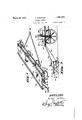
- Another object of the invention resides in the provision ofa stubble burner'of the character stated which; includes curvedspring arms or; runners ridingjfreely I over the, surface withlthe rake 'te'eth o erating on an,in--; cline between the*forwarcand rearspring arms-or runners, While the, burnerjpipeisj supported above the rake teeth with the burner jetsspaced 'alongmsor as to direct" the stubble destroying blaze directly towthe stub?" bleasit is'raised to upright position by the rake teeth.
- a further objectofthe invention resides provision of a Jstubble; burner ofjfthe.v
- theutransverse flame defiecting plate 6 serves. as theitop of: the stub? ble burnerstructureandha-sits-forward and, i rearv edges-respectivelyreinforced by angle;
- Theplatefi has secured Onitsun-j 7 der:face by bolts 7" orthe lilie', a plurality of longitudinally extended tstraps located near the, ends of the platefi and between the; ends and the centralportion of the latter, the straps 8 'being extended acrossthe'plate 6.
- ends 9 of the" strap'si8l' haveouteturned lower-extremities lOgsecured on the fronttransversebar or tube 11. of the, burnerstructure by appropriate 'securing members 12.
- braces 14a are also employed between the main. portions of the fully described; "illustrated in the accom- ZGHr TSP W-Z ms O Y H P .4;a h I rear edgeof the plate-6 to strengthen thi'sfpor-i" 7 tion ofitheq-structure and prevent tlierear edgerof theplate-(i frompressing down on the;
- a rake bar is carried in the ends of the plurality of U-shaped brackets 17 and secured therein by attaching members 18 past through the bar 16 and the brackets 17.
- the brackets 17 extend for wardly and have their bight portions 19 loosely mounted on the front bar or tube 11 and are prevented from moving forwardly on the latter by stop members 20 extended transversely through bight portions 19.
- the rake teeth 21 are extended on an incline through the rake bar 16, the teeth 21 being inclined rearwardly so as to effectively ride on the surface and raise to upright position all fallen stubble or stalks.
- a transverse burner pipe or nozzle 22 is extended beneath the plate '6, throughout the length thereof and has on its underside a plurality of spaced burner jets 23 directly above the lower ends of the rake teeth 21.
- the burner pipe or nozzle 22 is mounted on the depending end 24 of the fuel conductpipe 25, a portion 26 of which may be flex- 1 e if desired and connected with the valved discharge nozzle 27 of the fuel supply tank 28 mountedon the wagon 29 or other means employed for drawing the device over the surface.
- a divided flexible connection 30 is employed between the wagon 29 and the front bar 11 of the device and is shown in the form of a chain having a ring 31 removably en gaged with the clevis 32 on the end of a wagon 29, while the divided portions or ends of the chain are detachably mounted on the clevises 33-carried on the front bar 11. It may also be stated that the burner pipe or nozzle 22 is revented' from dropping away from the bottom of the plate 6, by means. of the stop collar 34 forming'part of the connection between the burner pipe or nozzle 22 and the depending end 24 of the fuel conducting pipe and resting on the upper face of the plate 6.
- the device is further permitted to operate efliciently over an uneven surface without interfering with the feeding of the fuel to the burner pipe or nozzle 22 or drawing of the device over the surface by the wa on29 or other draft means.
- Astubble burner includin a transversely elongated deflector plate; f ront and rear curved spring runners supported beneath said deflector plate; angle irons on the upper face of the forward and rear edges of said burner plate to'brace the same; brace bars between said rear curved spring runners and the rear ed e of said deflector plate; a front bar suspended below the front edge of said deflector plate; a rake structure mounted for swingingmovement on said front bar and beneath said deflector plate; a burner beneath said deflector plate andabove the said rake structure ;;-a fuel supply tank connected to said burner; and draft means extended from said front bar'of the said stubble burner.
- a stubble burner including a transversely elongated deflector plate having trailer rear spring supports, angular brackets depending from the front edge of said deflector plate; a lower ends of said angular'brackets'; forward spring supports attached to said bar; a rake structure mounted for swinging movement on said front bar; and a burnerat the underside of said deflector plate with burner jets directed toward the working ends of said rake.
Landscapes
- Life Sciences & Earth Sciences (AREA)
- Engineering & Computer Science (AREA)
- Insects & Arthropods (AREA)
- Pest Control & Pesticides (AREA)
- Wood Science & Technology (AREA)
- Zoology (AREA)
- Environmental Sciences (AREA)
- Finger-Pressure Massage (AREA)
- Catching Or Destruction (AREA)
- Cleaning Of Streets, Tracks, Or Beaches (AREA)
Description
March 29, 1932. WORTHLEY S'IUBBLF- BURNER Filed Sept. 16. 1929 2 Sheets-Sheet. 1
IN VEN TOR He I but Worth L e H March 29, 1932. H. WORTHLEY STUBBLE BURNER Filed sefit. 16. 1929 2 Sheets-Sheet 2 IN VENTOR Herbert WorThLeg H I s Attorn c g Patented Man 29," 1932 s'runtrn nunm Application:fileniSeptember16, 1929i;- Serial 'No. 3955;0875" I p This present'invention 1-elates,,to. new.and
useful improvements in fa stubble burner and,"
has for its primaryfobject the provision; of a compact, structure 'whichflmay be readily. drawn over the :surfaeeto liftnpthe lea-ning stalks and present them to the burner jets as the device passes oventhe stubbleso asjtoa assure thorough burningandcomplete-dc; struction of the stubblefasjwel-l as i'insects such aslocusts, grasshoppers, and the like,
and thereby clear ,theland for cultivation;
Another object of the invention'resides in the provision ofa stubble burner'of the character stated which; includes curvedspring arms or; runners ridingjfreely I over the, surface withlthe rake 'te'eth o erating on an,in--; cline between the*forwarcand rearspring arms-or runners, While the, burnerjpipeisj supported above the rake teeth with the burner jetsspaced 'alongmsor as to direct" the stubble destroying blaze directly towthe stub?" bleasit is'raised to upright position by the rake teeth.
j A further objectofthe invention resides provision of a Jstubble; burner ofjfthe.v
in the character stated includinga deflectingiplate beneathwhich are supported the rake teeth and the burner nozzle 'asr-wel-l as the'cur-ved springfarms or runn rs onyvthich the device r the minimum number ofpart's of simple and operates over the surface.
A still further objectfiof'the inventionr'esides in the provisionof'a' stubble burner of curved ,7 forward springcarmsor runners I which areturnedback upon themselves and;
the character stated which is;v constructed so that all of theparts thereof'are thoroughly;
braced and the complete device comp-osedfof inexpensive construction, and arrangement and I the stubble burner :is highlyfeflicient in operation. 7 i i V To the accomplishment of; "these" and re-v lated objects as'shall become apparent as the descriptionproceeds, my inventionresides in the construction, combination and arrange-:
ment of parts: as shalltbe hereinaftermore panylng drawln'gsand. pointed out-fin, the
- claims hereunto appended.
- The invention willbe best understood and,
-;can be more clearly described, when reference is had to the drawingsqfor'ming a part of Ithissdisclosure, wherein like characters vindica-te,likefparts throughout the several, VIEWS; e
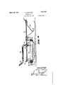
lnthe drawingske I V 1 Figured is a'perspective View ofrthe-im-E proved stubble burner; v I Fi ures is a vertical longitudinal section;
through the stubble burner; and r v Figure 8 is; a side elevation of the. stubble:
, burner, showing' the same carriedbehind .a
wagon orfthe like on which is mounted: the fuel supply tank for-the 'stubbleburner,
eferring. inorein detail ,tothe drawings, it will-betnoted that theutransverse flame defiecting plate 6 serves. as theitop of: the stub? ble burnerstructureandha-sits-forward and, i rearv edges-respectivelyreinforced by angle;
110118 60;, and 6b securedcon the upper face thereof. Theplatefihas secured Onitsun-j 7 der:face by bolts 7" orthe lilie', a plurality of longitudinally extended tstraps located near the, ends of the platefi and between the; ends and the centralportion of the latter, the straps 8 'being extended acrossthe'plate 6.. Depending forward, ends 9 of the" strap'si8l' haveouteturned lower-extremities lOgsecured on the fronttransversebar or tube 11. of the, burnerstructure by appropriate 'securing members 12. Mountedon the securing mem i hers: 12, intermediate theout turned extremi- Qties' 10 0f the ends 9 ofthe straps 8 -and the;
front bar or tube 11,,areth'eupper endsofthe curved rearwardly and slightly; upwardly beneath the-front bar or tube 11; Cooperat-x ing rear curved springarms; or'runners 14 re 15 0f the respective curved spring arms or; runn-ers l4. Appropriate braces 14a are also employed between the main. portions of the fully described; "illustrated in the accom- ZGHr TSP W-Z ms O Y H P .4;a h I rear edgeof the plate-6 to strengthen thi'sfpor-i" 7 tion ofitheq-structure and prevent tlierear edgerof theplate-(i frompressing down on the;
while the structure is heated, during operation of the stubble burner.
A rake bar, either hollow as shown or solid, and designated by the numeral 16, is carried in the ends of the plurality of U-shaped brackets 17 and secured therein by attaching members 18 past through the bar 16 and the brackets 17. The brackets 17 extend for wardly and have their bight portions 19 loosely mounted on the front bar or tube 11 and are prevented from moving forwardly on the latter by stop members 20 extended transversely through bight portions 19. The rake teeth 21 are extended on an incline through the rake bar 16, the teeth 21 being inclined rearwardly so as to effectively ride on the surface and raise to upright position all fallen stubble or stalks.
A transverse burner pipe or nozzle 22 is extended beneath the plate '6, throughout the length thereof and has on its underside a plurality of spaced burner jets 23 directly above the lower ends of the rake teeth 21. The burner pipe or nozzle 22 is mounted on the depending end 24 of the fuel conductpipe 25, a portion 26 of which may be flex- 1 e if desired and connected with the valved discharge nozzle 27 of the fuel supply tank 28 mountedon the wagon 29 or other means employed for drawing the device over the surface. A divided flexible connection 30 is employed between the wagon 29 and the front bar 11 of the device and is shown in the form of a chain having a ring 31 removably en gaged with the clevis 32 on the end of a wagon 29, while the divided portions or ends of the chain are detachably mounted on the clevises 33-carried on the front bar 11. It may also be stated that the burner pipe or nozzle 22 is revented' from dropping away from the bottom of the plate 6, by means. of the stop collar 34 forming'part of the connection between the burner pipe or nozzle 22 and the depending end 24 of the fuel conducting pipe and resting on the upper face of the plate 6.
As the construction of the device has thus been described in detail, brief reference is now had to its use and modus operandi: As the device is drawn over the surface it rides 1 on the front curved spring arms or runners 13 and the rear curved spring arms or runners 14 thus permitting the device to travel I over an uneven surface without materially interfering with eflicient operation of the device. The rake teeth 21 will engage and'raise to upright position any fallen or leaning stubble or grain stalks and the like and present them to the destroying blaze directed downwardlyfrom the burner jets 23. The
'* weight of the rake bar 16 and rake teeth 21 will'result in thelatter being maintained on the surface and as the supporting brackets 17 for the rake bar 16 are free to swing on the front bar 11 of the device, this efficient functioning of the rake teeth 21 will continue,
the brackets 17, near their.
regardless of the unevenness of the surface and the resulting raising or dropping of one or more of the curved spring arms or runners 13 and 14. Owing to the connection and the portion 26 of the pipe 25, both being flexible, the device is further permitted to operate efliciently over an uneven surface without interfering with the feeding of the fuel to the burner pipe or nozzle 22 or drawing of the device over the surface by the wa on29 or other draft means.
rom the foregoing description taken in connection with the accompanying drawings, it will be manifest that a stubble burner is provided that will fulfill all the necessary reqliliirements of such a device but as many 0 anges could be made in the above description and many apparently widely different embodiments of my invention may be constructed within the scope of the appended claims without departing from the spirit or scope thereof, it is intended that all matters contained in the said accompanying specification and drawings, shall be interpreted as illustrative and not in a limited sense.
Having thus described my invention, what I claim as new and desire to secure by Letters Patent is 2-- I 1. Astubble burner includin a transversely elongated deflector plate; f ront and rear curved spring runners supported beneath said deflector plate; angle irons on the upper face of the forward and rear edges of said burner plate to'brace the same; brace bars between said rear curved spring runners and the rear ed e of said deflector plate; a front bar suspended below the front edge of said deflector plate; a rake structure mounted for swingingmovement on said front bar and beneath said deflector plate; a burner beneath said deflector plate andabove the said rake structure ;;-a fuel supply tank connected to said burner; and draft means extended from said front bar'of the said stubble burner.
2. A stubble burner including a transversely elongated deflector plate having trailer rear spring supports, angular brackets depending from the front edge of said deflector plate; a lower ends of said angular'brackets'; forward spring supports attached to said bar; a rake structure mounted for swinging movement on said front bar; and a burnerat the underside of said deflector plate with burner jets directed toward the working ends of said rake. i v
In testimony whereof I hereunto afiix my signature.
HERBERT WORTHLEY. [us] front bar attached to the 1
Priority Applications (1)
| Application Number | Priority Date | Filing Date | Title |
|---|---|---|---|
| US393037A US1851379A (en) | 1929-09-16 | 1929-09-16 | Stubble burner |
Applications Claiming Priority (1)
| Application Number | Priority Date | Filing Date | Title |
|---|---|---|---|
| US393037A US1851379A (en) | 1929-09-16 | 1929-09-16 | Stubble burner |
Publications (1)
| Publication Number | Publication Date |
|---|---|
| US1851379A true US1851379A (en) | 1932-03-29 |
Family
ID=23553014
Family Applications (1)
| Application Number | Title | Priority Date | Filing Date |
|---|---|---|---|
| US393037A Expired - Lifetime US1851379A (en) | 1929-09-16 | 1929-09-16 | Stubble burner |
Country Status (1)
| Country | Link |
|---|---|
| US (1) | US1851379A (en) |
Cited By (4)
| Publication number | Priority date | Publication date | Assignee | Title |
|---|---|---|---|---|
| US4256086A (en) * | 1978-08-28 | 1981-03-17 | Collett Kenneth R | Method for rapidly igniting combustible material on a field |
| US5682707A (en) * | 1995-02-01 | 1997-11-04 | Chastain; Julius H. | Agricultural burner implement |
| US20130061569A1 (en) * | 2010-11-03 | 2013-03-14 | Dean J. McClenathen | Device for flattening corn stalk stubbles |
| US20150250098A1 (en) * | 2014-03-04 | 2015-09-10 | Deere & Company | Stalk Breaker for a Corn Head |
-
1929
- 1929-09-16 US US393037A patent/US1851379A/en not_active Expired - Lifetime
Cited By (4)
| Publication number | Priority date | Publication date | Assignee | Title |
|---|---|---|---|---|
| US4256086A (en) * | 1978-08-28 | 1981-03-17 | Collett Kenneth R | Method for rapidly igniting combustible material on a field |
| US5682707A (en) * | 1995-02-01 | 1997-11-04 | Chastain; Julius H. | Agricultural burner implement |
| US20130061569A1 (en) * | 2010-11-03 | 2013-03-14 | Dean J. McClenathen | Device for flattening corn stalk stubbles |
| US20150250098A1 (en) * | 2014-03-04 | 2015-09-10 | Deere & Company | Stalk Breaker for a Corn Head |
Similar Documents
| Publication | Publication Date | Title |
|---|---|---|
| US1851379A (en) | Stubble burner | |
| US2545723A (en) | Rotary side delivery rake | |
| US3038665A (en) | Tractor attached spray apparatus | |
| US1656171A (en) | Plant-spraying apparatus | |
| US2636328A (en) | Rock picker | |
| US1624421A (en) | Road drag | |
| US1436958A (en) | Insect exterminator | |
| US2166596A (en) | Road drag | |
| US1696888A (en) | Portable burning apparatus | |
| US1415491A (en) | Weed and insect burner | |
| US1581406A (en) | Apparatus for | |
| US1619516A (en) | Stubble burner | |
| US1521424A (en) | Boll-weevil exterminator | |
| US2858646A (en) | Orchard heater | |
| US1452918A (en) | Insect destroyer | |
| US2576930A (en) | Device for setting backfires | |
| US1531975A (en) | Weeder | |
| US1604910A (en) | Pneumatic collecting apparatus | |
| US1808654A (en) | Poison or powder distributor | |
| US1435483A (en) | Weed-destroying machine | |
| US1580297A (en) | Insect-exterminating apparatus | |
| US2157968A (en) | Self-propelled combined earth scooping and conveying-off apparatus | |
| US1243327A (en) | Stone-rake. | |
| US1401614A (en) | larson | |
| US2661675A (en) | One-way disk harrow or plow |